ita 400 us - hvac tech · pdf fileita 400 40.021.070 - rev 00 - 2013 7 english ita/itas-us...
TRANSCRIPT
USER MANUAL
ITA 400 US

2 40.021.070 - rev 00 - 2013 ITA 400 US SU-SATI/ATI1102 - 40 .ver - 549.020.042
/i
- 2 - - 1 -
- 3 -
- 4 - - 5 -
Fabr.year 0000 Serial nr: 00.0000
Made by THERMOBILE Ind. B.V. Breda, Holland
000.000.00edoc.dorPUTB 000,000oturb yticapaCUTB 000,000otten yticapaC
MFC 000,0wolfriAisp 000erusserp pmuP
Outlet temp. by 68° F
leseid 2.oN ro 1.oNleuFkerosene or fuel oil
Fuel consumption 0,00 Gallon/hrEl.con 120V/60Hz/9 Amp.
000° - 000° F
ABCDEFGHI
J
K
A
A
BC
Max. 451000 mm
O
A
B
A B C D G H K L M
NO
PQRSTUV
W
X

340.021.070 - rev 00 - 2013ITA 400 US 31102 - 40 .ver - 549.020.04SU-SATI/ATI
/i
/i
/i
- 6 -
0.31 in
0.18 in
AC
ITA 100
B
12
34
56
78
D
Nr. ITA 400 US
A 0.2 in
6B
C 0.08 in
ni 24.0 D

4 40.021.070 - rev 00 - 2013 ITA 400 US4 40.020.945 - rev. 04 - 2011 ITA/ITAS-US
- 7 -
A B C E
FGH
D

540.021.070 - rev 00 - 2013ITA 400 US 51102 - 40 .ver - 549.020.04SU-SATI/ATI
English ...........................................6
6 40.021.070 - rev 00 - 2013 ITA 400 US
ENGLISH
6 40.020.945 - rev. 04 - 2011 ITA/ITAS-US
English
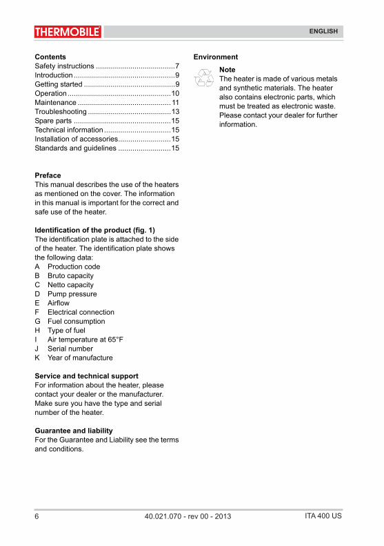
EnglishContentsSafety instructions .......................................7Introduction ..................................................9Getting started .............................................9Operation ...................................................10Maintenance ..............................................11Troubleshooting .........................................13Spare parts ................................................15Technical information .................................15Installation of accessories..........................15Standards and guidelines ..........................15
PrefaceThis manual describes the use of the heaters as mentioned on the cover. The information in this manual is important for the correct and safe use of the heater.
Identification of the product (fig. 1)The identification plate is attached to the side of the heater. The identification plate shows the following data:A Production codeB Bruto capacityC Netto capacityD Pump pressureE AirflowF Electrical connectionG Fuel consumptionH Type of fuelI Air temperature at 65°FJ Serial numberK Year of manufacture
Service and technical supportFor information about the heater, please contact your dealer or the manufacturer. Make sure you have the type and serial number of the heater.
Guarantee and liabilityFor the Guarantee and Liability see the terms and conditions.
Environment
NoteThe heater is made of various metals and synthetic materials. The heater also contains electronic parts, which must be treated as electronic waste. Please contact your dealer for further information.

740.021.070 - rev 00 - 2013ITA 400 US
ENGLISH
ITA/ITAS-US 40.020.945 - rev. 04 - 2011 7
English
1 SAFETY INSTRUCTIONS
1.1 Pictograms in this manual
1.2 Pictograms on the heater (fig. 2)A Pump pressure
1.3 Use in conformity with destinationThe heater is designed for use on construction sites, in poultry houses, workshops, storage rooms, warehouses, greenhouses and polyurethane tunnels and to dry agricultural products and bulbs.
1.4 Use this product for the purpose it was intended for
The convector heater was designed for use indoors and outdoors. The heater can be used for the heating of tents, building sites, showrooms, sports halls, storage sheds, workshops, round-the-clock projects, warehouses, greenhouses, polytunnels, spray arrangements, and for the drying of agricultural produce and bulbs.
1.5 General instructions
CautionA caution shows a danger that can cause damage to the equipment.
WarningA warning shows a hazard that can cause death or serious injury.
WarningWhen working on the heater for maintenance or repair works always disconnect the electric power!
HotSome surfaces are hot! Wait until these parts are cooled down sufficiently before maintenance is carried out.
Suggestions and advice for conducting the relevant tasks or activities more easily.
CautionIf the heater will be installed indoors, make sure that there is proper ventilation in the room. Make sure the flue gas can only flow to an outside source separate from the room.
Warning• For all service and adjustments
contact qualified, competent and authorized persons.
• Make sure to always follow the local standards and guidelines as well as the local requirements.
• Make sure to read this manual carefully before using the convector heater.
• Keep this document near the convector heater.
• Follow the procedures described.• Do not lean on the convector
heater.• Do not tamper with the heater.
Adjustments may only be made by specially trained personnel.
• Do not operate the unit near combustibles.
• Keep at least 7 ft away from the exhaust opening of the convector heater.
• Make sure there is sufficient air for proper combustion.
• Make sure there is no highly flammable material near the convector heater.
8 40.021.070 - rev 00 - 2013 ITA 400 US
ENGLISH
8 40.020.945 - rev. 04 - 2011 ITA/ITAS-US
English
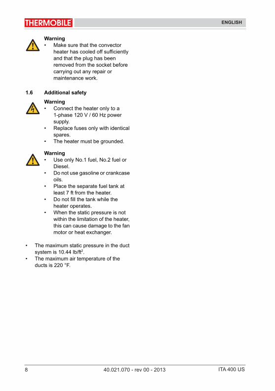
1.6 Additional safety
• The maximum static pressure in the duct system is 10.44 lb/ft2.
• The maximum air temperature of the ducts is 220 °F.
Warning• Make sure that the convector
heater has cooled off sufficiently and that the plug has been removed from the socket before carrying out any repair or maintenance work.
Warning• Connect the heater only to a
1-phase 120 V / 60 Hz power supply.
• Replace fuses only with identical spares.
• The heater must be grounded.
Warning• Use only No.1 fuel, No.2 fuel or
Diesel.• Do not use gasoline or crankcase
oils.• Place the separate fuel tank at
least 7 ft from the heater.• Do not fill the tank while the
heater operates.• When the static pressure is not
within the limitation of the heater, this can cause damage to the fan motor or heat exchanger.

940.021.070 - rev 00 - 2013ITA 400 US
ENGLISH
91102 - 40 .ver - 549.020.04SU-SATI/ATI
English
2 INTRODUCTION
2.1 PurposeThe heaters are indirectly fired heaters with photocell control and connections for a room thermostat and flue with raincover. The heaters are tested at sea level and at a temperature of 68 °F.
2.2 Working principleAn electric motor drives a fan and fuel pump. The pump draws the fuel from the tank to a magnetic valve. The fan blows air into and around the combustion chamber. The magnetic valve opens 12 seconds after switching on the heater and the fuel flows into the nozzle. A spark between the electrodes ignites the atomised fuel and starts a flame. The light from the flame activates a photocell. After the safety time the ignition switches off. The magnetic valve closes when you switch off the heater, or as a result of a fault, the flame stops.The fan runs until a thermostat switches the fan off: the cooling cycle is complete.
2.3 Main components (fig. 3)A Fuel tank filterB GrillC FanD Electric motorE Magnetic valveF Electrode (2x)G Burner headH Air slide valveI PhotocellJ After cooling safety thermostatK Combustion chamber/heat exchangerL Flue connectionM Maximum thermostatN Fuel tank (not for ITAS series)O Drain plugP On/Off switchQ Reset buttonR Identification plateS Air inlet burner (only for ITA 45, ITAS 45)T Fuel pump
U Connector for room thermostatV Cable with plugW Fuel filterX Push bar frame
2.4 Accessories• Flue with raincover• Room thermostat• Single outlet with duct • Manifold with duct• Wheels with tyres (only for ITA 45 and
ITA 75).
3 GETTING STARTED
3.1 Remove packaging Remove the packaging from the heater.
3.2 Installation1. Make sure that the heater is placed
horizontally.2. Fill the tank with fuel.
3. Make sure there is sufficient distance between the wall and the air inlet. Minimum distance is 4 ft.
4. Make sure that the heated air can flow without obstruction. Minimum distance from outlet to an obstacle is 7 ft.
CautionUse only No. 1 fuel, No. 2 fuel or Diesel.
Caution
• Be careful when you fill the tank. Remove any spilled oil from the heater and the ground.
• Gas oil tends to thicken at low temperatures. This can block the filters. Add a maximum of 15% paraffin to the fuel at temperatures below -20 °F, or keep the fuel frost-proof, or use tank heating (optional).
10 40.021.070 - rev 00 - 2013 ITA 400 US
ENGLISH
10 40.020.945 - rev. 04 - 2011 ITA/ITAS-US
English
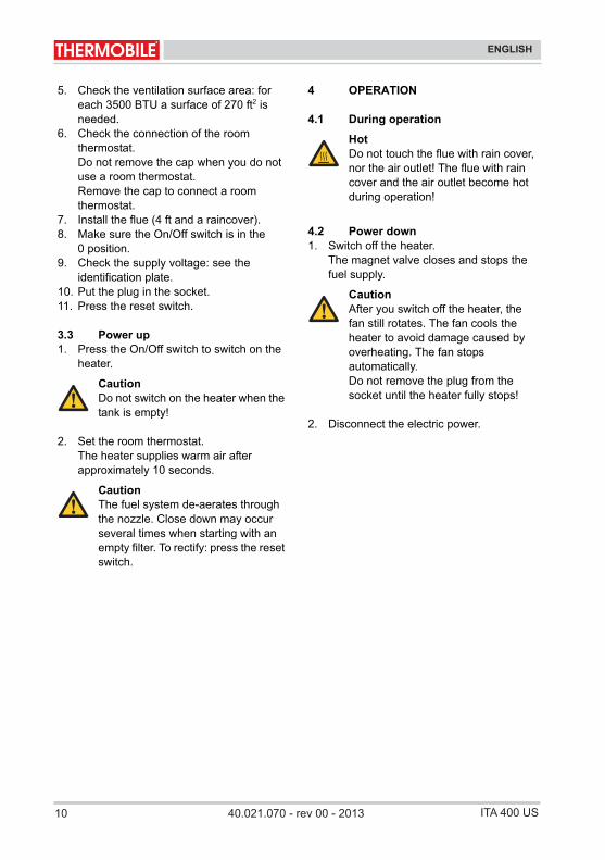
5. Check the ventilation surface area: for each 3500 BTU a surface of 270 ft2 is needed.
6. Check the connection of the room thermostat.Do not remove the cap when you do not use a room thermostat.Remove the cap to connect a room thermostat.
7. Install the flue (4 ft and a raincover).8. Make sure the On/Off switch is in the
0 position.9. Check the supply voltage: see the
identification plate.10. Put the plug in the socket.11. Press the reset switch.
3.3 Power up1. Press the On/Off switch to switch on the
heater.
2. Set the room thermostat.The heater supplies warm air after approximately 10 seconds.
4 OPERATION
4.1 During operation
4.2 Power down1. Switch off the heater.
The magnet valve closes and stops the fuel supply.
2. Disconnect the electric power.
CautionDo not switch on the heater when the tank is empty!
CautionThe fuel system de-aerates through the nozzle. Close down may occur several times when starting with an empty filter. To rectify: press the reset switch.
HotDo not touch the flue with rain cover, nor the air outlet! The flue with rain cover and the air outlet become hot during operation!
CautionAfter you switch off the heater, the fan still rotates. The fan cools the heater to avoid damage caused by overheating. The fan stops automatically.Do not remove the plug from the socket until the heater fully stops!
1140.021.070 - rev 00 - 2013ITA 400 US
ENGLISH
ITA/ITAS-US 40.020.945 - rev. 04 - 2011 11
English
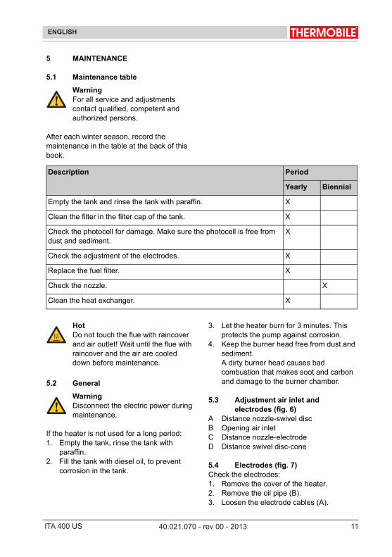
5 MAINTENANCE
5.1 Maintenance table
After each winter season, record the maintenance in the table at the back of this book.
/i
5.2 General
If the heater is not used for a long period:1. Empty the tank, rinse the tank with
paraffin.2. Fill the tank with diesel oil, to prevent
corrosion in the tank.
3. Let the heater burn for 3 minutes. This protects the pump against corrosion.
4. Keep the burner head free from dust and sediment.A dirty burner head causes bad combustion that makes soot and carbon and damage to the burner chamber.
5.3 Adjustment air inlet and electrodes (fig. 6)
A Distance nozzle-swivel discB Opening air inletC Distance nozzle-electrodeD Distance swivel disc-cone
5.4 Electrodes (fig. 7)Check the electrodes:1. Remove the cover of the heater.2. Remove the oil pipe (B).3. Loosen the electrode cables (A).
WarningFor all service and adjustments contact qualified, competent and authorized persons.
Description Period
Yearly Biennial
Empty the tank and rinse the tank with paraffin. X
Clean the filter in the filter cap of the tank. X
Check the photocell for damage. Make sure the photocell is free from dust and sediment.
X
Check the adjustment of the electrodes. X
Replace the fuel filter. X
Check the nozzle. X
Clean the heat exchanger. X
HotDo not touch the flue with raincover and air outlet! Wait until the flue with raincover and the air are cooled down before maintenance.
WarningDisconnect the electric power during maintenance.

12 40.021.070 - rev 00 - 2013 ITA 400 US
ENGLISH
12 40.020.945 - rev. 04 - 2011 ITA/ITAS-US
English
4. Remove the screws (G).5. Remove the burner head.6. Clean and re-adjust the electrodes (C).
The electrodes must be free of dirt, grease, fuel etc.If the points of the electrodes are burned too much and adjustment is impossible: replace the electrodes.
7. Loosen the screw (F).8. Re-adjust the electrodes.Install the burner head in the reverse order.
Replace the electrodes:1. Do the points 1 to 7 of “Check the
electrodes”.2. Replace the electrodes.3. Adjust the electrodes.Install the burner head in the reverse order.
5.5 Nozzle (fig. 7)
Check the nozzle:1. Remove the cover of the heater.2. Remove the oil pipe (B).3. Loosen the electrode cables (A).4. Remove the screws (G).5. Remove the burner head (H).6. Check the nozzle (D).
If the nozzle is black, because of soot or coke: replace the nozzle.
Install the burner head in the reverse order.
Replace the nozzle:1. Do the points 1 to 6 of “Check the
nozzle”.2. Remove the electrodes (C).3. Remove the swivel disc (E).4. Remove the nozzle (D).5. Replace the nozzle: use the correct type!6. Install the swivel disc.7. Readjust the electrodes, see fig. 6.Install the burner head in the reverse order.
5.6 Photocell (fig. 5)Check the photocell:1. Remove the cover of the heater.2. Remove the photocell out of the holder
pipe (A).3. Clean the photocell if the glass is
black (B).If the glass is cracked: the photocell must be replaced by the dealer.
Install the photocell in the reverse order.
WarningDo not touch the filter of the nozzle. This will damage the nozzle.
1340.021.070 - rev 00 - 2013ITA 400 US
ENGLISH
ITA/ITAS-US 40.020.945 - rev. 04 - 2011 13
English
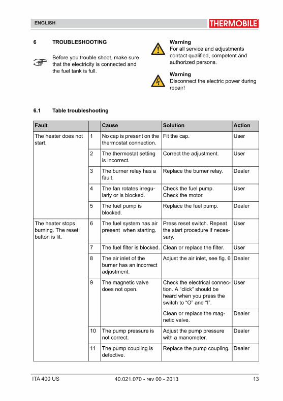
6 TROUBLESHOOTING
6.1 Table troubleshooting/i
Before you trouble shoot, make sure that the electricity is connected and the fuel tank is full.
WarningFor all service and adjustments contact qualified, competent and authorized persons.
WarningDisconnect the electric power during repair!
Fault Cause Solution Action
The heater does not start.
1 No cap is present on the thermostat connection.
Fit the cap. User
2 The thermostat setting is incorrect.
Correct the adjustment. User
3 The burner relay has a fault.
Replace the burner relay. Dealer
4 The fan rotates irregu-larly or is blocked.
Check the fuel pump.Check the motor.
User
5 The fuel pump is blocked.
Replace the fuel pump. Dealer
The heater stops burning. The reset button is lit.
6 The fuel system has air present when starting.
Press reset switch. Repeat the start procedure if neces-sary.
User
7 The fuel filter is blocked. Clean or replace the filter. User
8 The air inlet of the burner has an incorrect adjustment.
Adjust the air inlet, see fig. 6 Dealer
9 The magnetic valve does not open.
Check the electrical connec-tion. A “click” should be heard when you press the switch to “O” and “I”.
User
Clean or replace the mag-netic valve.
Dealer
10 The pump pressure is not correct.
Adjust the pump pressure with a manometer.
Dealer
11 The pump coupling is defective.
Replace the pump coupling. Dealer

14 40.021.070 - rev 00 - 2013 ITA 400 US
ENGLISH
14 40.020.945 - rev. 04 - 2011 ITA/ITAS-US
English
The heater stops burning. The reset button is lit.
12 The suction line or main filter has an air leak.
Check and replace if neces-sary.
User
13 The protection grill for the air intake is dirty or blocked.
Clean the grill. User
14 The fresh air supply is not sufficient.
Open a door or a window. User
15 The photocell dirty. Clean the photocell, see fig. 5.
User
16 The heat exchanger is blocked.
Clean the heat exchanger. User
17 The overheating ther-mostat is activated or defective.
Trace cause. Reset, or if necessary replace the ther-mostat.See faults 1 and 9.
User
The heater produces smoke.
18 The nozzle is blocked or worn.
Replace the nozzle. User
19 The suction line or main filter has an air leak.
Check and replace if neces-sary.See faults 8, 10, 13 and 14.
User
The heater produces white smoke.
20 The fuel system has air. See fault 6. User
The heater uses too much fuel.
21 The nozzle is too big or the wrong type is used.
Replace the nozzle with the correct one.
User
Check the fuel pipes. User
See faults 10 and 18.
Heater cannot be switched off.
22 The magnetic valve does not close.
Remove the fuel line from the filter to extinguish the flame.
User
Clean or replace the mag-netic valve.
Dealer
The cooling thermo-stat does not switch on/off.
23 The automatic cooling does not work.
Remove the fuel line from the filter: the flame will extin-guish.
Dealer
The automatic cooling does not work / does not stop.
24 The after cooling ther-mostat does not switch on/off.
Cooling is required for 4 minutes. Remove the plug from the socket.
Dealer
Fault Cause Solution Action
1540.021.070 - rev 00 - 2013ITA 400 US 511102 - 40 .ver - 549.020.04SU-SATI/ATI
English
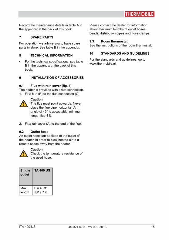
Record the maintenance details in table A in the appendix at the back of this book.
7 SPARE PARTS
For operation we advise you to have spare parts in store. See table B in the appendix.
8 TECHNICAL INFORMATION
• For the technical specifications, see table B in the appendix at the back of this book.
9 INSTALLATION OF ACCESSORIES
9.1 Flue with rain cover (fig. 4)The heater is provided with a flue connection.1. Fit a flue (B) to the flue connection (C).
2. Fit a raincover (A) to the end of the flue.
9.2 Outlet hoseAn outlet hose can be fitted to the outlet of the heater, in order to blow heated air to a remote space away from the heater.
/i
Please contact the dealer for information about maximum lengths of outlet hoses, bends, distribution pipes and hose clamps.
9.3 Room thermostatSee the instructions of the room thermostat.
10 STANDARDS AND GUIDELINES
For the standards and guidelines, go to www.thermobile.nl.
CautionThe flue must point upwards. Never place the flue pipe horizontal. An angle of 45° is acceptable; minimum length flue 4 ft.
CautionCheck the temperature resistance of the used hose.
Single outlet
ITA 400 US
Max. length ∅19.7 in
L = 40 ft:

16 40.021.070 - rev 00 - 2013 ITA 400 USITA/ITAS-US 40.020.945 - rev. 04 - 2011 37
Español
/i
A
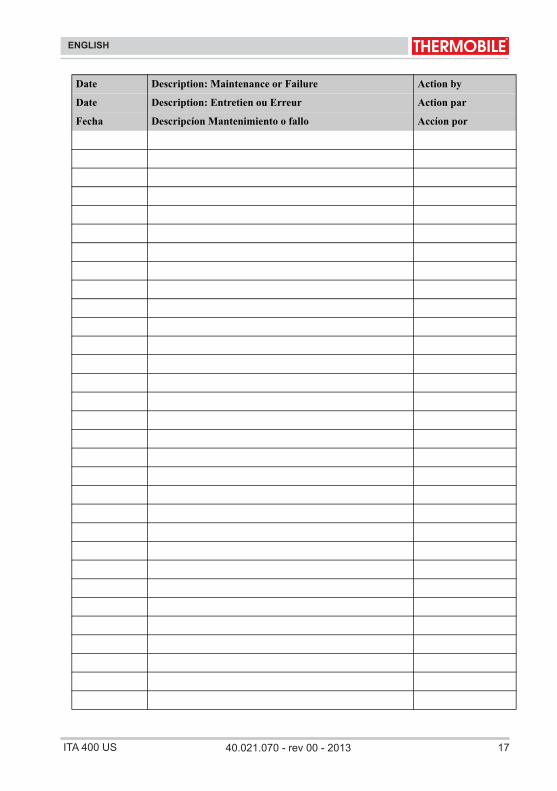
Date Description: Maintenance or Failure Action by
Date Description: Entretien ou Erreur Action par
Fecha Descripcíon Mantenimiento o fallo Accíon por
1740.021.070 - rev 00 - 2013ITA 400 US
ENGLISH
38 40.020.945 - rev. 04 - 2011 ITA/ITAS-US
Español
Date Description: Maintenance or Failure Action by
Date Description: Entretien ou Erreur Action par
Fecha Descripcíon Mantenimiento o fallo Accíon por
18 40.021.070 - rev 00 - 2013 ITA 400 US
ENGLISH
931102 - 40 .ver - 549.020.04SU-SATI/ATI
Español
/i
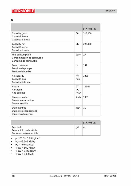
B
/i
• ρ (15° C): 0.85 kg/dm3
• Hi = 42.689 MJ/kg• Hs = 45.5 MJ/kg• 1 kW = 860 kcal/h• 1 kW = 3413 Btu/h• 1 kW = 3.6 MJ/h
ITA 400 US
Capacity, grossCapacité, bruteCapacidad, bruta
Btu
Capacity, netCapacité, netteCapacidad, neta
Btu
Fuel consumptionConsommation de combustileConsumo de combustile
gal/h
Pump pressurePression de pompePresión de bomba
ps
Air capacityCapacité d’airCapacidad de aire
ft3/min
Hot airAir chaudAire caliente
ΔT (°C)°F-°C
Diameter outletDiamètre évacuationDiámetro salida
inch
Diameter Diamètre échappementDiámetro chimenea
inch
Fuel tankRéservoir à combustibleDepósito de combustible
gal
325,000
297,000
2,4
152
3200
122-50
19,7
7,9
61
ITA 400 US

1940.021.070 - rev 00 - 2013ITA 400 US

40.0
21.0
70 -
rev
00 -
2013
THERMOBILE INDUSTRIES BVKonijnenberg 804825 BD Breda Nederland
Postbus 33124800 DH Breda Nederland Bedrijfsnummer: 3502
T +31 (0)76 587 34 50 F +31 (0)76 587 27 [email protected]
THERMOBILE UK LTD12, Buckingham CloseBermuda Industrial EstateNuneaton, WarwickshireCV10 7JT Groot-Brittannië
T +44 (0)2476 35 79 60F +44 (0)2476 35 79 [email protected] www.thermobile.co.uk
THERMOBILE FRANCE sarl3, rue Denis Papin45240 LA FERTÉ ST. AUBIN Frankrijk
T +33 (0)2 38 76 59 25F +33 (0)2 38 76 58 [email protected] www.thermobile.fr
Member of the Honing Beheer Group of Companies
Thermobile Industries B.V.