it20300 string theory—dynamo for absolute...
TRANSCRIPT

Page 1
IT20300
String Theory—Dynamo for Absolute Beginners Jason Howden RTV Tools Limited
Description No coding or Dynamo experience required. This presentation is a grass-roots presentation to get you started with taking advantage of the power of design automation using the Dynamo extension. We will explore the Dynamo interface and discover where useful resources are on the Internet to build some powerful timesaving workflows that can automate the boring and mundane so you can spend more time on designing. This session features Revit and Dynamo Studio. Your AU Expert(s) Jason is passionate about design, technology, innovation, mountain biking, fast red cars, the great outdoors and fishing. My passion for BIM and technology in Architecture has allowed me to reach beyond the borders of New Zealand providing BIM consultancy services all over the world including London, Sydney, Perth, Brisbane, Stockholm, Jakarta and Abu Dhabi. In my spare time, I run my software company RTV Tools providing automation tools for Revit to a growing list of international clients including Fortune 500 listed corporations. Jason’s passion for design technologies has been applied to complex projects across the aviation, healthcare, research, institutional, commercial, and residential sectors including the Spark Towers, Wellington NZ (5D BIM); the new Terminal 3 building, Jakarta Soekarno-Hatta International Airport (3D BIM); Centre for Obesity, Diabetes and Cardiovascular Disease research laboratory, Sydney University (3D BIM); and the Spring Hill Corrections Facility (BIM in a Collaborative Working Alliance) in New Zealand.
Learning Objectives • Understand how to use Dynamo and navigate the interface; • Learn where to find the best learning materials for Dynamo; • Learn how to create your first timesaving Dynamo script; and • Learn how to create a script to randomize a façade, and automate workset
management in Revit.

Page 2
Contents Learning Objectives ............................................................................................................... 1
Description ............................................................................................................................ 1
Your AU Expert(s) .................................................................................................................. 1
What is Dynamo?................................................................................................................... 5
How can I use Dynamo? ........................................................................................................ 5
Where can I find useful resources? ......................................................................................... 6
Dynamo User Interface .......................................................................................................... 7
Nodes ................................................................................................................................ 8
Wires ................................................................................................................................. 9
Library.............................................................................................................................. 10
Program Management.......................................................................................................... 11
Alignment ......................................................................................................................... 11
Notes ............................................................................................................................... 12
Grouping .......................................................................................................................... 12
Nodes the Building Blocks of a Program ............................................................................ 13
Data ................................................................................................................................. 13
Geometry Blocks .............................................................................................................. 13
List Blocks ........................................................................................................................ 14
Revit Specific Blocks ........................................................................................................ 14
Custom Packages ............................................................................................................ 15
Example 1 – Selecting Elements .......................................................................................... 18
Step 1. – Getting Started................................................................................................... 18
Step 2. – Into Dynamo ...................................................................................................... 18
Step 3. – Creating our first Nodes...................................................................................... 18
Step 4. – Right Click Menu ................................................................................................ 19
Step 5. – ‘Wire’ the Nodes ................................................................................................ 20
Step 6. – Select your Elements in Revit ............................................................................. 21
Step 7. – Run your Code................................................................................................... 21
Step 8. – Expanding your Code ......................................................................................... 22
Step 9. – Adding another Watch Point ............................................................................... 22
Step 10. – Select ALL Walls .............................................................................................. 23
Step 11. – Selecting Walls by Type ................................................................................... 23
Step 12. – Add a Watch Node ........................................................................................... 24

Page 3
Step 13. – Select the Wall Type ........................................................................................ 24
Step 14. – Select a Curtain Wall ........................................................................................ 25
Step 15. – Analysing Sub-Elements .................................................................................. 25
Step 16. – Extracting Parameter Data ............................................................................... 26
Step 17. – Extracting Parameter Data cont. ....................................................................... 27
Step 18. – Define the Parameter to Extract ........................................................................ 28
Step 19. – Extracting Materials from Elements ................................................................... 29
Step 20. – Get the Material Name ..................................................................................... 29
Step 21. – Extending the Data Extraction........................................................................... 30
Step 22. – Extracting the Area of Elements ........................................................................ 31
Step 23. – Rounding the Data ........................................................................................... 31
Step 24. – Connect the Nodes .......................................................................................... 32
Step 25. – Setting the amount of Rounding ........................................................................ 32
Example 2 – Working with Dynamo Lists............................................................................... 33
Step 1. – Getting Started................................................................................................... 33
Step 2. – Into Dynamo ...................................................................................................... 33
Step 3. – Making a simple Cylinder ................................................................................... 33
Step 4. – Creating a Circle ................................................................................................ 34
Step 5. – Draw the Circles ................................................................................................ 35
Step 6. – Create the Cylinder ............................................................................................ 36
Step 6. – Twisting the Cylinder .......................................................................................... 37
Step 7. – Twisting the Cylinder 2 ....................................................................................... 38
Example 3 – Randomising a Curtain Wall ............................................................................. 39
Step 1. – Getting started ................................................................................................... 39
Step 2. – Jump into Dynamo ............................................................................................. 39
Step 3. – Select the Walls by Type .................................................................................... 40
Step 4. – Select the Sub-elements .................................................................................... 40
Step 5. – Create a Watch point ......................................................................................... 41
Step 6. – Flatten the List ................................................................................................... 42
Step 7. – Making a Randomiser ........................................................................................ 42
Step 8. – Keeping the Code Tidy ....................................................................................... 43
Step 9. – Making a Panel Type Selector ............................................................................ 43
Step 10. – Creating a % of Wall Selector ........................................................................... 44
Step 11. ........................................................................................................................... 44

Page 4
Step 12. – Selecting the Panel Type .................................................................................. 45
Step 13. – Tidy up your Code ............................................................................................ 45
Step 14. – Adding coverage Zones .................................................................................... 46
Step 15. – Finalising the Randomiser ................................................................................ 47
Step 16. – Running the Randomiser .................................................................................. 47
Example 4 – Working with Excel Data ................................................................................... 48
Step 1. – Getting started ................................................................................................... 48
Step 2. – Jump into Dynamo ............................................................................................. 48
Step 3. – Create a select from File Node ........................................................................... 48
Step 4. – Reading the Excel Spreadsheet .......................................................................... 49
Step 5. – Reformatting the Raw Data ................................................................................ 50
Step 6. – Extracting what we want ..................................................................................... 51
Step 7. – Create Worksets in Revit .................................................................................... 52
Step 8. – Play it with Dynamo Player ................................................................................. 52
Example 5 – Setting Element Worksets from Excel ............................................................... 53
Step 1. – Getting Started................................................................................................... 53
Step 2. – Jump into Dynamo ............................................................................................. 53
Step 3. – Create a select from File Node ........................................................................... 53
Step 4. – Reading the Excel Spreadsheet .......................................................................... 54
Step 5. – Formatting the Raw Data .................................................................................... 55
Step 6. – Filtering the formatted Data ................................................................................ 56
Step 7. – Mapping the Workset Names to Workset IDs ...................................................... 57
Step 8. – Separating the Subcategories from Worksets ...................................................... 58
Step 9. – Get all Model Elements ...................................................................................... 59
Step 10. – Removing Invalid (Nulls) Data........................................................................... 60
Step 11. – Replace Zero Value with 1 ................................................................................ 61
Step 12. – Map the Workset IDs to Model Elements ........................................................... 62
Step 13. – Set the Workset for the selected Model Elements .............................................. 63
Step 14. – Connect to your Workset Excel Template and Run ............................................ 64
Special thanks too! ............................................................................................................... 65

Page 5
What is Dynamo? Dynamo is a software application both stand-alone and a plugin that sits within other applications like Revit. Dynamo uses Visual Programming to build and run processes (algorithms) within the native software by connecting nodes (small/parts of programs) together to form an overall process (program/script). These Dynamo processes can be used to generate geometry, automate repetitive tasks, or to generate iterative solutions to design problems.
VISUAL PROGRAM EXAMPLE: SOURCE DYNAMOPRIMER.COM How can I use Dynamo? Dynamo can be for a wide range of process and activities in Revit including;
• Geometry; • Parameter and Data manipulation; • View and Sheet creation; and • Whatever your imagination aspires to explore.
DYNAMO EXAMPLES: SOURCE DYNAMOPRIMER.COM

Page 6
Where can I find useful resources? There are many places where you can find useful resources to learn how to use Dynamo, and find examples of useful Dynamo Nodes and Scripts, some of these include; • DynamoPrimer.com – This website provides a comprehensive guide to visual
programming in Dynamo. Includes a step by step list to each of the functions within Dynamo and examples files. http://dynamoprimer.com/index.html
• Dynamo 101 – Is an introductory course that explains the very basics of Dynamo. This course has been compiled by Konrad K. Sobon, an experienced Architect and programmer working for Grimshaw Architects in NYC. https://thinkparametric.com/courses/dynamo-101-fundamentals
• Archi+Lab – This website or blog is one of the essential reading sites for anyone looking to work smarter. It contains a collection of tips, tricks and other useful workflow examples that apply to the AEC industry. This site is also authored by Konrad K. Sobon. http://archi-lab.net/
• DynamoNodes – Is a very good blog focusing on stitching together Standard, or out of the box (OOTB) Dynamo Nodes to form productivity enhancing workflows. This site is authored by Luke Johnson who is an experienced BIM Manager working for Virtual Built in Adelaide, Australia. https://dynamonodes.com/
• DynamoPackages – Share and discover Dynamo packages and programs to extend your Visual Programming library. https://dynamopackages.com/
A list of other useful sites that I would recommend and follow myself can be found at the back of this handout under special thanks too!...

Page 7
Dynamo User Interface (SOURCE DYNAMOPRIMER.COM)
The User Interface (UI) for Dynamo is organised into five main regions, the largest of which is the workspace where we compose our visual programs.
DYNAMO EXAMPLES: SOURCE DYNAMOPRIMER.COM
1. Menus – The drop down menus provide a place to access some of the basic functions within Dynamo (File, Edit, View, Packages, Settings and Help)
2. Toolbar – The toolbar provides quick access to key functions within Dynamo (New, Open, Save/Save As, Undo, Redo and Export Workspace as Image [camera icon] which is useful for capturing screenshots of your Dynamo programs)
3. Library – Dynamo node library, this is where you will find the nodes that you can wire together to create your Dynamo programs. I find the Search and Add function on the library bar the most useful functions. Search allows you to quickly search for a Dynamo node, while Add allows you to search for published Dynamo Packages on the internet.
4. Workspace – This is where you create your Dynamo programs. 5. Execution Bar – This is where you Run or Execute your Dynamo programs.

Page 8
Nodes Nodes are the objects you connect to form a Visual Program. Each Node performs an operation sometimes they may be as simple as storing a number or more complex such as creating geometry or analyzing data. Most Nodes in Dynamo are composed of five parts. While there are exceptions, such as Input Nodes, the anatomy of each Node can be described as follows:
DYNAMO NODE: SOURCE DYNAMOPRIMER.COM
1. Name – The Name of the Node with a <Category>.<Name> naming convention; 2. Main – The main body of the Node - Right-clicking here presents options at the level of
the whole Node; 3. Ports (In and Out) – The receptors for Wires that supply the input data to the Node as
well as the results of the Node's action or program; 4. Data Preview – Hover or click to see a tooltip describing the results of the Node's action
(similar to and saves using the Watch node); 5. Lacing Icon – Indicates the Lacing option specified for matching list inputs.

Page 9
Wires Wires connect between Nodes to create relationships and establish the flow or sequence of your program. Think of them as electrical wires that carry pulses of data from one object to the next. Wires connect the output Port from one Node to the input Port of another Node. This establishes the flow or sequence of your program. Although we can arrange the Nodes however we desire in the Workspace because the output Ports are located on the right side of Nodes, and the input Ports are on the left side, we can generally say that the Program Flow moves from left to right, see example below.
EXAMPLE OF THE FLOW OF A DYNAMO PROGRAM: SOURCE DYNAMOPRIMER.COM
We create Wires by left clicking the mouse on a Port and then left clicking on the port of another Node to create a connection between them. While we are in the process of making a connection, the Wire will appear dashed and will become solid when successfully connected.

Page 10
Library The Dynamo Library is a collection of functional libraries or packages, each containing Nodes grouped by Category. While this may seem a little weird at first, it is a flexible framework for organising the Nodes. The Library section of the Dynamo UI is composed of hierarchically organised libraries. As we drill down into the Library, we are sequentially browsing a library, the library's categories and the category's sub-categories to find the desired Node.
DYNAMO LIBRARY: SOURCE DYNAMOPRIMER.COM
1. The Library – The Library region of the Dynamo Interface; 2. A Library – A collection of related Categories, such as Geometry; 3. A Category – A collection of related Nodes such as everything related to Circles; 4. A Subcategory – Breakdown of the Nodes within the Category, typically by Create,
Action, or Query; 5. A Node – The objects that are added to the Workspace to perform an action.

Page 11
Program Management Working with Visual Programming can be a powerful and creative activity, but very quickly your program can become messy and complex due to poor layout of the Nodes within the Workspace. It is best practice to manage your program by sticking to some very simple layout rules (Alignment, Notes, and Grouping).
Alignment Once you have added more than a few Nodes into the Workspace, re-organize the layout of the Nodes to provide some clarity to the intended flow and process behind your program. This is done quickly by selecting more than one Node and right-clicking on the Workspace, the pop-up window includes an Align Selection menu with justification and distribution options in X and Y.
DYNAMO ALIGNMENT: SOURCE DYNAMOPRIMER.COM
1. Select more than one Node 2. Right-click on the Workspace 3. Use the Align Selection options

Page 12
Notes It is good practice to include some plain language “breadcrumbs” behind in your Dynamo Program so other users of your program can understand what your intent was and how the program functions. Dynamo provides a Notes Node with an editable text field to allow you to record any notes you want to leave behind in your program. We can add Notes to the Workspace in two ways;
1. Browse to the menu File > Create Note 2. Use the keyboard shortcut Ctrl+W
Grouping Another usual tool for organising your Visual Program and to leave behind some useful “breadcrumbs” for other users of your program is to Group the Nodes into logical function or result. Groups can be labelled with a title and are identified with a coloured rectangle in the background.
DYNAMO GROUPS: SOURCE DYNAMOPRIMER.COM
1. Note: "Grid Parameters" 2. Note: "Grid Points" 3. Group: "Create a Grid of Points" 4. Group: "Create an Attractor Point" 5. Note: "Calibrate Distance Values" 6. Note: "Variable Grid of Circles"

Page 13
Nodes the Building Blocks of a Program Nodes are the building blocks of your Dynamo programs. Understanding what Nodes are available for use in your programs and how they function is key to creating innovative Dynamo programs that will save to time and money. Nodes are groups into useful Categories that represent their intended function including Data, Geometry, Lists, and a series of Revit specific functions.
Data We need data to add to the input Ports of Dynamo's Nodes - we can have data without actions but we need data to process the actions that our Nodes represent. The simplest form of data is a number such as 0, 3.14, or 17. But data can also be of a number of different types: a Variable representing changing numbers; Characters or a name; Geometry; or a List of items (1,2,3,5,8,13,...). Data Nodes includes functions that relate to Math (Arithmetic Operators), Logic (If this Then), Strings (Text) and Color Nodes.
Geometry Blocks Dynamo has a rich and extensive list of Nodes for creating and manipulating geometry, especially in Revit. Geometry Nodes cover Curves, Surfaces, Solids, Meshes, Topology, Points, Import Geometry and Abstract functions.
DYNAMO GEOMETRY NODES: SOURCE DYNAMOPRIMER.COM

Page 14
List Blocks Lists are organize data in Dynamo, understanding how to use and manipulate Lists in Dynamo will determine how successful your Dynamo programs will be. In Dynamo, you can Create, Modify and Query lists of data.
DYNAMO LIST NODES: SOURCE DYNAMOPRIMER.COM
Revit Specific Blocks Dynamo offers a suite of Nodes specifically designed for Revit. Using Dynamo with Revit will allow you to extend Revit beyond it’s out of the box capabilities and toolsets to an almost unlimited level for creative design and documentation. Revit Nodes cover Selecting, Editing, Creating, Analysis, and Documenting functions.

Page 15
Custom Packages – Useful tools for free
Bumblebee for Dynamo (Excel and Dynamo = BIM Heaven)
Bumblebee provides enhanced Excel to Dynamo functions and is a must have package in your Dynamo Library.
BUMBLEBEE FOR DYNAMO: SOURCE ARCHI-LAB.NET

Page 16
Dynaworks for Dynamo (Dynamo and Navisworks = Gone fishing)
DynaWorks is another must have packages, and provides a series of Dynamo Nodes for interacting with Navisworks files.
DYNAWORKS FOR DYNAMO: SOURCE DYNAMONODES.COM
Archi-lab.net and Archi-Nodes for Dynamo (Set of practical nodes)
A selection of practical and useful Nodes developed for the AEC industry. A must to add to your Dynamo Library. Clockwork for Dynamo (Don’t leave home without this Dynamo Package)
Clockwork is a collection of 360+ custom nodes. It contains many Revit-related nodes, but also lots of nodes for various other purposes such as list management, mathematical operations, string operations, geometric operations (mainly bounding boxes, planes, points, surfaces, UVs and vectors) and paneling. For more information visit https://github.com/andydandy74/ClockworkForDynamo

Page 17
Lunchbox for Dynamo (another collection of must have Dynamo Nodes)
LunchBox is a set of computational design tools for Grasshopper and Dynamo. The plugins include new component nodes for managing data and geometry for activities such as generative form making, paneling, rationalization, and interoperability. With over 8000 users, LunchBox is the most downloaded tool for Dynamo.
LUNCHBOX FOR DYNAMO: SOURCE PROVINGGROUND.IO
Rhythm for Dynamo (consists of out of the box Dynamo nodes used in clever ways as they apply to the Revit environment)

Page 18
Example 1 – Selecting Elements In this exercise, we will explore different ways of selecting model elements in Revit. After completing this exercise, you will be able to select and extract key parameters from model elements in Dynamo.
Step 1. – Getting Started Open the following file String_Theory_Example_1 - Start.rvt
Step 2. – Into Dynamo Start Dynamo (1.2.0)
Step 3. – Creating our first Nodes 1. In the Search Bar start typing Select Model Element. 2. From the Library select the Node Select Model Element. 3. The Select Model Element should now appear in the Dynamo workspace.

Page 19
Step 4. – Right Click Menu Now right mouse click on the Workspace to active the right click menu. You can use this to search and select Dynamo Nodes from the Library. 1. Start typing Watch into the Search Bar on the right click menu. 2. Select the Watch Node. You can use the Watch Node to view the data that has been
analysed by your Dynamo functions.

Page 20
Step 5. – ‘Wire’ the Nodes Now connect (Wire) the two Nodes together. 1. Start by selecting Element output port on the Select Model Element Node, and while the
Wire is dashed 2. Drag it to the input port or the > on the Watch Node.
Page 21
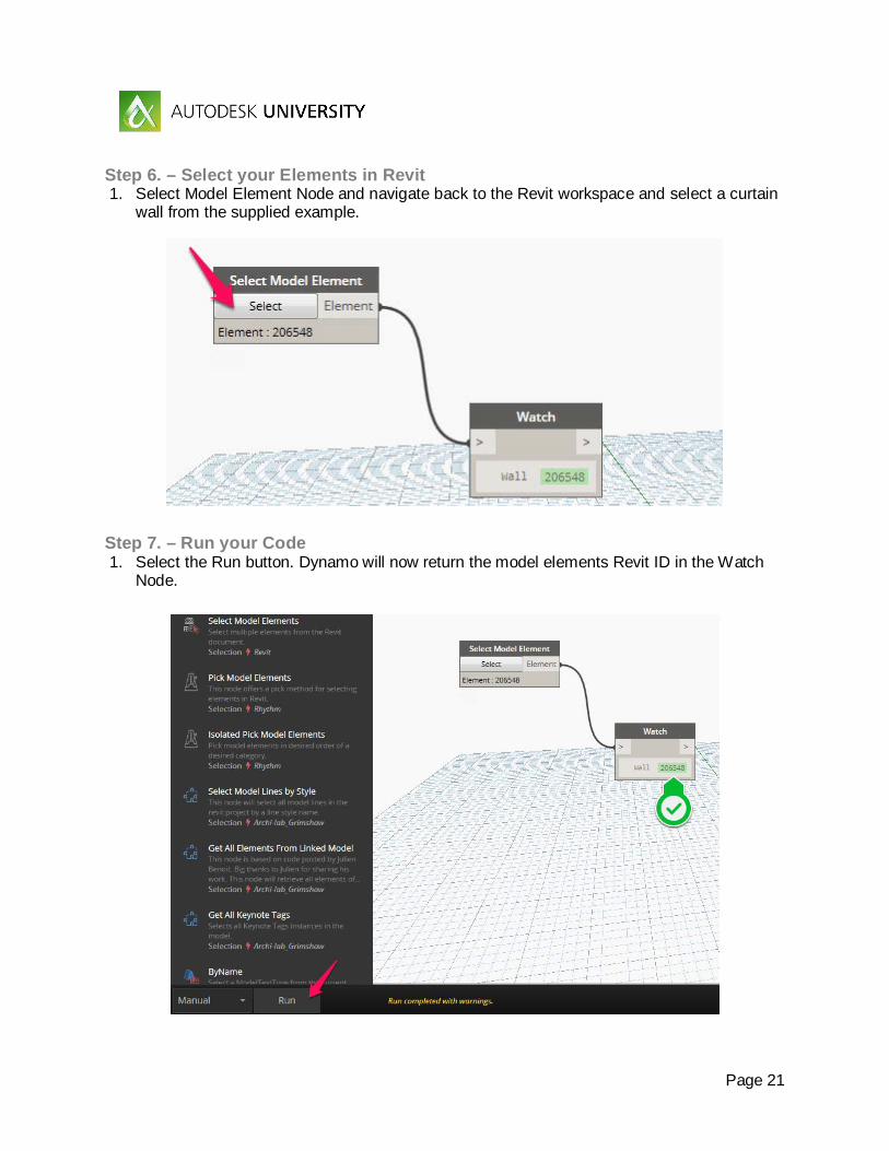
Step 6. – Select your Elements in Revit 1. Select Model Element Node and navigate back to the Revit workspace and select a curtain
wall from the supplied example.
Step 7. – Run your Code 1. Select the Run button. Dynamo will now return the model elements Revit ID in the Watch
Node.

Page 22
Step 8. – Expanding your Code We are now going to explore selecting all the walls on a specified Revit category. 1. Right click in the Dynamo Workspace and start typing Categories. 2. Select the Categories Node from the right click menu. The new Node will now appear in
the Dynamo Workspace.
Step 9. – Adding another Watch Point Now Wire the Categories Node to the existing Watch Node. 1. Select the Categories output port and drag the wire to 2. The Watch input port
Page 23
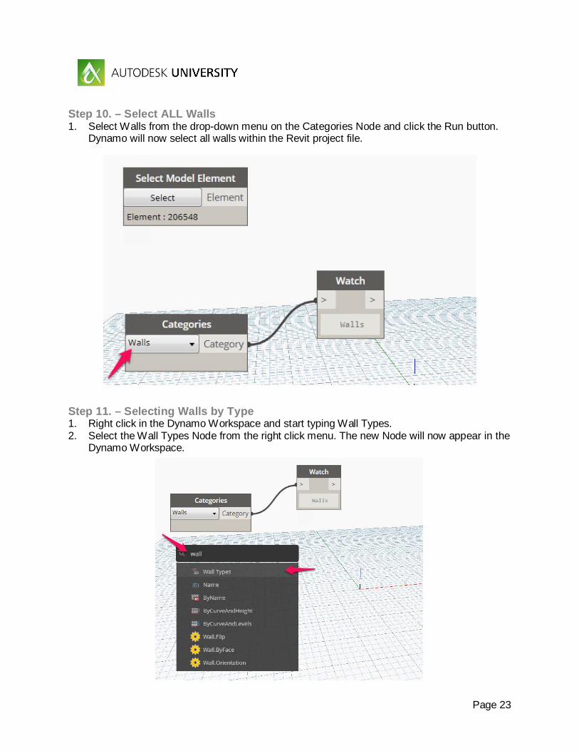
Step 10. – Select ALL Walls 1. Select Walls from the drop-down menu on the Categories Node and click the Run button.
Dynamo will now select all walls within the Revit project file.
Step 11. – Selecting Walls by Type 1. Right click in the Dynamo Workspace and start typing Wall Types. 2. Select the Wall Types Node from the right click menu. The new Node will now appear in the
Dynamo Workspace.

Page 24
Step 12. – Add a Watch Node 1. Now Wire the Wall Types Node to the existing Watch Node.
Step 13. – Select the Wall Type 1. Select Glass 12mm Fixed Vert 500 Hori 500 from the drop down menu on the Wall
Types Node and click the Run button. Dynamo will now select all walls of the select wall types within the Revit project file.

Page 25
Step 14. – Select a Curtain Wall The next few steps we are going to explore how to extract and analyze the data within the selected model elements. Let’s start by extracting the curtain panel elements from the curtain wall. To keep things simple lets, go back to the Select Model Element Node so we are working with just one curtain wall element. 1. In the Dynamo Library Search bar and start typing Curtain Panel By Element. 2. Select the ByElement Node from the Library menu. The new Node will now appear in the
Dynamo Workspace.
Step 15. – Analysing Sub-Elements 1. Now connect (Wire) the Select Model Element Node to the new CurtainPanel.ByElement
Node, and finally connect this to a new Watch Node. 2. After connecting the Nodes 3. Select the Model Element using the Select or Change button and selecting the desired
curtain wall model element. Now click Run. You should now see the individual model element IDs of each curtain panel in the Watch Node.

Page 26
Step 16. – Extracting Parameter Data Now that we have made a List or selected all the curtain panels of our wall, let’s use Dynamo to extract some key parameter data about these panels. We will now use Dynamo to extract the Material Name and Area of each of the panels. 1. In the Dynamo Library Search bar and start typing Get Parameter Value By Name, I
prefer to use the Node produced by Rhythm as it is much more universal than the out of the box version (OOTB).
2. Make sure you select the GetParameterValueByName(TypeOrInstance) Node by Rhythm from the Library menu. The new Node will now appear in the Dynamo Workspace.

Page 27
Step 17. – Extracting Parameter Data cont. 1. Now Wire the CurtainPanel.ByElement Node to the 2. GetParameterValueByName(TypeOrInstance) Node using the Element input port, and
connect to the 3. Watch Node.

Page 28
Step 18. – Define the Parameter to Extract Now we need to define what parameter we want to analyze, the simplest way of doing this (in my opinion) is to use a simple Code Block Node. Code Block Nodes are very versatile and can contain all sorts of data including programs such as Python. To insert a new Code Block simply double click on a blank part of the Dynamo Workspace and a new Code Block will appear at the place. 1. Type the following into the new Code Block Node where is says “Your code goes here”,
“Material”. 2. Now Wire the Code Block into the GetParameterValueByName(TypeOrInstance) Node
using the ParameterName input port and click Run to see the resulting material IDs.

Page 29
Step 19. – Extracting Materials from Elements Now that we have made a List of all the curtain panel materials, let’s use Dynamo to extract the real-world name of the materials.
1. In the Dynamo Library Search bar and start typing Element Name. 2. Select the Name Node from the Library menu, making sure it is the Element not the Family
name Node. The new Node will now appear in the Dynamo Workspace. 3. Wire the GetParameterValueByName(TypeOrInstance) Node into the Element.Name Node
using the Element input port.
Step 20. – Get the Material Name 1. Wire the Element.Name Node into a Watch Node and click Run to get a List of the curtain
wall panels’ materials.

Page 30
Step 21. – Extending the Data Extraction We are now going to copy the Nodes used in Steps 17 and 18 to create a duplicate program “branch” to analyse the area of each panel in the curtain wall. 1. Select the Code Block and GetParameterValueByName(TypeOrInstance) Nodes and
CRTL+C and CRTL+V to copy and paste a copy of these Nodes. You will notice that doing this also keeps the Wires in place.

Page 31
Step 22. – Extracting the Area of Elements Rename or type the following “Area” into the copied Code Block and add a new Watch Node. 1. Wire the GetParameterValueByName(TypeOrInstance) Node into the Watch Node and click Run to get a List of the curtain wall panels areas.
Step 23. – Rounding the Data Finally let’s add some rounding to the List of areas. In the Dynamo Library Search bar and start typing Math Round To Precision.
1. Select the Math.RoundToPrecision Node by Clockwork from the Library menu. The new Node will now appear in the Dynamo Workspace.

Page 32
Step 24. – Connect the Nodes Wire the GetParameterValueByName(TypeOrInstance) Node into the Math.RoundToPrecision Node using the dbl input port and Wire the Math.RoundToPrecision Node into the Watch Node.
Step 25. – Setting the amount of Rounding Add a new Code Block Node and type 0.001 into it. Wire the Code Block Node into the precision Node and click Run.

Page 33
Example 2 – Working with Dynamo Lists (SOURCE DYNAMO PRIMER)
In this exercise we will explore different ways of managing lists of data in Dynamo. After completing this exercise you will be able to create, manage and manipulate lists of data in Dynamo.
Step 1. – Getting Started Open the following file String_Theory_Example_2 - Start.rfa
Step 2. – Into Dynamo Start Dynamo (1.2.0)
Step 3. – Making a simple Cylinder Let’s start by creating a simple cylinder made up of lines to explore how having a good understanding of managing a List in Dynamo can bring some interesting results.
1. Create a new Code Block with 0 for the value. 2. Using the Dynamo Search bar locate and add the Point By Coordinates Node. 3. Wire the Code Block Node into the x,y and z input port of the Point.ByCoordinates Node. 4. Using the Dynamo Search bar locate and add the Plane By Origin Normal Node. 5. Wire the Point.ByCoordinates Node into the origin input port of the Plane.ByOriginNormal
Node.

Page 34
Step 4. – Creating a Circle Using the Dynamo Search bar locate and add the Circle By Plane Radius Node. 1. Wire the Plane.ByOriginNormal Node into the plane input port of the
Circle.ByPlaneRadius Node. 2. Create a new Code Block Node with 50 for the value. 3. Wire the Code Block Node into the radius input port of the Circle.ByPlaneRadius Node. 4. Using the Dynamo Search bar locate and add the Geometry Translate Node. 5. Wire the Circle.ByPlaneRadius Node into the geometry input port of the
Geometry.Translate Node. 6. Create a new Code Block Node with 100 for the value. 7. Wire the Code Block Node into the zTranslation input port of the Geometry.Translate
Node.

Page 35
Step 5. – Draw the Circles 1. Using the Dynamo Search bar locate and add the Curve Point At Parameter Node. Do this
twice. 2. Wire the Geometry.Translate Node into the curve input port of one of the
Curve.PointAtParameter Nodes. 3. Wire the Circle.ByPlaneRadius Node into the curve input port of the other
Curve.PointAtParameter Node. 4. Create a new Code Block Node with 0..1..0#30 for the value. 5. Wire the Code Block Node into the param input port of both of the Curve.PointAtParameter
Nodes. 6. Using the Dynamo Search bar locate and add the Line By Start Point End Point Node. 7. Wire one of the Curve.PointAtParameter Nodes into the startPoint input port of both of the
Line.ByStartPointEndPoint Node. 8. Wire the other Curve.PointAtParameter Node into the endPoint input port of both of the
Line.ByStartPointEndPoint Node. 9. Using the Dynamo Search bar locate and add the List Count Node. 10. Wire the Line.ByStartPointEndPoint Node into the list input port of the List.Count Node.

Page 36
Step 6. – Create the Cylinder 1. Click Run to create the Cylinder.

Page 37
Step 6. – Twisting the Cylinder Let’s add a Reverse List Node into the Dynamo program. 1. Using the Dynamo Search bar locate and add the List Reverse Node. 2. Wire one of the Curve.PointAtParameter Nodes into the list input port of the List.Reverse
Node. 3. Wire the List.Reverse Node into the endPoint input port of the Line.ByStartPointEndPoint
Node. 4. Click Run to view the results.

Page 38
Step 7. – Twisting the Cylinder 2 Now let’s substitute the Reverse List Node for the List Shift Indices Nodes. 1. Using the Dynamo Search bar locate and add the List Shift Indices Node. 2. Create a new Code Block with a value of 10. 3. Wire the Code Block Node into the amount input port of the List.ShiftIndices Node. 4. Wire one of the Curve.PointAtParameter Nodes into the list input port of the List.ShiftIndices
Node. 5. Wire the List.ShiftIndices Node into the endPoint input port of the Line.ByStartPointEndPoint
Node. 6. Click Run to view the results.

Page 39
Example 3 – Randomising a Curtain Wall In this exercise we will explore the creation of a random façade generator in Dynamo. We will use Dynamo to select a curtain wall, analyse the panels within the curtain wall, and to randomly swap out the curtain wall panel types based on a percentage of coverage for each new panel type. After completing this exercise you have a fully functioning random façade generator in Dynamo.
Step 1. – Getting started Open the following file String_Theory_Example_3 - Start.rvt
Step 2. – Jump into Dynamo Start Dynamo (1.2.0)

Page 40
Step 3. – Select the Walls by Type The first step is to create the selection part of the Dynamo program. 1. Using the Dynamo Search bar locate and add the following Nodes, Wall Types and All
Elements of Family Type (Universal) by Clockwork. 2. Wire the Wall Types Node into the familyType input port of the All Elements of Family Type
(Universal) Node.
Step 4. – Select the Sub-elements 1. Using the Dynamo Search bar locate and add the Curtain Panel By Element Node. 2. Wire the All Elements of Family Type (Universal) Node into the hostingElement input
port of the CurtainPanel.ByElement Node.

Page 41
Step 5. – Create a Watch point Let’s create a check point now. 1. Add a new Watch Node and Wire the CurtainPanel.ByElement Node into it. 2. Using the drop down menu on the Wall Types Nodes select Glass 12mm Fixed Vert 500
Hori 500 and click Run.
You should notice that we have a List of Lists within Lists. One list for each curtain wall in the project file, with a list of curtain wall panels within each. The next step is to reformat this overall List to just have a single List of just the curtain wall panels.

Page 42
Step 6. – Flatten the List 1. Using the Dynamo Search bar locate and add the List Flatten Node, next add a new
Code Block Node and type 1 into it. 2. Wire the CurtainPanel.ByElement Node into the List input port of the List.Flatten Node
and the Code Block into the amt input port of the List.Flatten Node. 3. Wire the List.Flatten Node to the Watch Node and click Run to see the flattened list of
curtain wall panels.
Step 7. – Making a Randomiser In this step we will make a randomiser to randomise the list of curtain panels. This list will then be used to define random curtain panels within the curtain wall or façade. 1. Using the Dynamo Search bar locate and add the following Nodes, Number Slider and
Manage Randomise Order by LunchBox. 2. Wire the Number Slider Node into the Seed input port of the Manage.RandomiseOrder
Node. 3. Set the Min, Max and Step of the Number Slide Node. These values will be used to
“seed” the randomised order of the curtain panels List. You are free to choose your own number, but I would recommend a step of 1.
4. Finally Wire the List.Flatten Node into the Data input port of the Manage.RandomiseOrder Node.

Page 43
Step 8. – Keeping the Code Tidy Let’s group the Number Slider and Manage.RandomiseOrder Nodes to keep our Dynamo program tidy as well as guiding other users of the program as to how it functions. 1. Shift and Left click the Number Slider and Manage.RandomiseOrder Nodes, once
highlighted Right click and select Create Group. Give the new group a title that will help to explain its function to users of your program.
Step 9. – Making a Panel Type Selector In this step we will make curtain panel type selector. This part of the Dynamo program allows the end user to define the desired curtain panel type and the percentage of coverage to be applied to the overall facade. 1. Using the Dynamo Search bar locate and add the List Slice Node. Add a new Code Block
with a value of 0 and Wire this into the Start input port of the List.Slice Node.

Page 44
Step 10. – Creating a % of Wall Selector In this step we will add some Nodes to slice a given percentage of the overall List. This will allow us to control the percentages of the panel types to be randomised. 1. Add two new Code Block Nodes, in the first type 0.2 and in the second type x*y. 2. Wire the first Code Block Node to the second Code Block Node using the y input port. 3. Wire the second Code Block Node into the End input port of the List.Slice Node.
Step 11. 1. Using the Dynamo Search bar locate and add the Count Node. This will be used later to
connect the original flattened List of curtain panels to complete the percentage calculation of this part of the program.
2. Wire the Count Node into the x input port of the second Code Block.

Page 45
Step 12. – Selecting the Panel Type In this step we will now create the actual curtain panel type selector. By using the drop down menu users of this program will be able to define the panel type to be used in the façade randomiser. 1. Add a new Code Block and type “Type” into it. 2. Using the Dynamo Search bar locate and add the following Nodes Family Types and
Element Set Parameter By Name. 3. Wire the Code Block into the parameterName input port, and Wire the Family Type Node
into value input port of the Element.SetParameterByName Node. 4. Finally Wire the List.Slice Node into the element input port of the
Element.SetParameterByName Node.
Step 13. – Tidy up your Code Let’s tidy up our program again, this time grouping the key components of the curtain panel type selector. 1. Shift and Left click, or Left click and drag to create a selection window all the Nodes except
for the Count Node, once highlighted Right click and select Create Group. Give the new group a title that will help to explain its function to users of your program.
Page 46
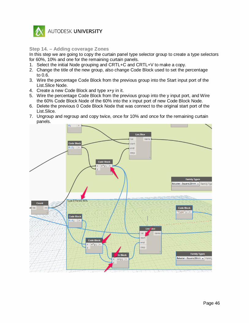
Step 14. – Adding coverage Zones In this step we are going to copy the curtain panel type selector group to create a type selectors for 60%, 10% and one for the remaining curtain panels. 1. Select the initial Node grouping and CRTL+C and CRTL+V to make a copy. 2. Change the title of the new group, also change Code Block used to set the percentage
to 0.6. 3. Wire the percentage Code Block from the previous group into the Start input port of the
List.Slice Node. 4. Create a new Code Block and type x+y in it. 5. Wire the percentage Code Block from the previous group into the y input port, and Wire
the 60% Code Block Node of the 60% into the x input port of new Code Block Node. 6. Delete the previous 0 Code Block Node that was connect to the original start port of the
List.Slice. 7. Ungroup and regroup and copy twice, once for 10% and once for the remaining curtain
panels.

Page 47
Step 15. – Finalising the Randomiser To create the Dynamo Nodes to select the remaining curtain panels we can remove the percentage Code Block Nodes, but be sure to leave the List.Slice and type selector Nodes. 1. Wire the last x+y Code Block Node into the Start input port and Wire the Count Node from
Step 11 into the End input port of the List.Slice Node.
Step 16. – Running the Randomiser Now select the Wall Type and each of the Family Types for the curtain panels and click Run to test. By adjusted the Slider Bar and re-running the program you can iterate through randomized façade patterns. Also experiment with different % settings.

Page 48
Example 4 – Working with Excel Data In this exercise we will explore the creation of a workset generator in Dynamo. We will use Dynamo to select an Excel spreadsheet, analyse the worksheets within the Excel spreadsheet, and read the data stored within the Excel spreadsheet to create the required worksets. After completing this exercise you have a fully functioning workset creator in Dynamo.
Step 1. – Getting started Open the following file String_Theory_Example_4 - Start.rvt After opening the files create the default Worksets Workset1 and Shared Levels and Grids, and save the file as a new Central file, be sure to save the Central file twice to relinquish the newly created Worksets.
Step 2. – Jump into Dynamo Start Dynamo (1.2.0)
Step 3. – Create a select from File Node The first step is to create the file selector to select and read the Excel file in which the data is stored to create the worksets from. 1. Using the Dynamo Search bar locate and add the following Nodes, File Path and File
From Path Nodes. 2. Wire the File Path Node into the path input port of the File.FromPath Node.

Page 49
Step 4. – Reading the Excel Spreadsheet In this step we are going to read the contents of the selected Excel file. 1. Using the Dynamo Search bar locate and add the following Nodes, Excel Read From File
(you can use the OOTB Node for this) and Boolean Nodes, and set the Boolean Node to True.
2. Wire the File.FromPath Node into the file input port of the Excel.ReadFromFile Node. 3. Wire the Boolean Node into the readAsStrings input port of the Excel.ReadFromFile Node. 4. Lastly create a new Code Block Node and type “Sheet1” into it. Wire the Code Block Node
into the sheetName input port of the Excel.ReadFromFile Node.

Page 50
Step 5. – Reformatting the Raw Data In this step we need to reformat the raw data into a List format suitable to create the Worksets from. 1. Using the Dynamo Search bar locate and add the following Nodes, List Remove Items
At Index and List Transpose Nodes. We will use the List.RemoveItemAtIndex to remove the header row in the Excel file. List.Transpose is used to convert the raw data from Columns and Rows into a set of Lists of Lists.
2. Add a new Code Block with 0 in it. 3. Wire the Excel.ReadFromFile Node into the list input port of the List.RemoveItemAtIndex
Node. 4. Wire the Code Block Node into the indices input port of the List.RemoveItemAtIndex
Node. 5. Wire the List.RemoveItemAtIndex Node into the lists input port of the List.Transpose
Node.

Page 51
Step 6. – Extracting what we want In this step we will use Dynamo to get a list of the unique Worksets in the Excel file. 1. Using the Dynamo Search bar locate and add the following Nodes;
a. List Get Item At Index; and b. List Unique Items Nodes.
We will use the List.GetItemAtIndex to select the sub-List which corresponds to the column in the Excel file where the Workset data is stored. The List.UniqueItems Node is used to get only the unique Worksets from the List.
2. Add a new Code Block with 2 in it. 3. Wire the List.Transpose Node into the list input port of the List.GetItemAtIndex Node. 4. Wire the Code Block Node into the index input port of the List.GetItemAtIndex Node. 5. Wire the List.GetItemAtIndex Node into the list input port of the List.UniqueItems Node.

Page 52
Step 7. – Create Worksets in Revit The last step is to create the Worksets in your Revit project file. 1. Using the Dynamo Search bar locate and add the Workset Create Node by Rhythm. 2. Wire the List.UniqueItems Node into the worksetNames input port of the Workset.Create
Node. Click Run to create your worksets in Revit.
Step 8. – Play it with Dynamo Player Tip: Add this Dynamo Script to Dynamo Player to automatically create Worksets from an Excel ‘Template’ to provide a ‘one click’ Workset creation workflow.

Page 53
Example 5 – Setting Element Worksets from Excel In this exercise we will explore the creation of a workset manager in Dynamo. We will use Dynamo to select an Excel spreadsheet, analyse the worksheets within the Excel spreadsheet, and to correctly place model elements onto the specified workset. After completing this exercise you have a fully functioning workset manager in Dynamo.
Step 1. – Getting Started Open the following file String_Theory_Example_5 - Start.rvt After opening the files create the default Worksets Workset1 and Shared Levels and Grids, and save the file as a new Central file, be sure to save the Central file twice to relinquish the newly created Worksets.
Step 2. – Jump into Dynamo Start Dynamo (1.2.0) Important: Run the completed Dynamo program from Example 4 to create the required Worksets for this example. Remember: Save to Central and to relinquish the newly created Worksets. 1. Start a new Dynamo program.
Step 3. – Create a select from File Node The first step is to create the file selector to select and read the Excel file in which the data is stored to create the worksets from. 1. Using the Dynamo Search bar locate and add the following Nodes, File Path and File From
Path Nodes. 2. Wire the File Path Node into the path input port of the File.FromPath Node.

Page 54
Step 4. – Reading the Excel Spreadsheet In this step we are going to read the contents of the selected Excel file. 1. Using the Dynamo Search bar locate and add the following Nodes, Excel Read From
File (you can use the OOTB Node for this) and Boolean Nodes, and set the Boolean Node to True.
2. Wire the File.FromPath Node into the file input port of the Excel.ReadFromFile Node. 3. Wire the Boolean Node into the readAsStrings input port of the Excel.ReadFromFile
Node. 4. Lastly create a new Code Block Node and type “Sheet1” into it. Wire the Code Block
Node into the sheetName input port of the Excel.ReadFromFile Node.

Page 55
Step 5. – Formatting the Raw Data In this step we need to reformat the raw data into a List format suitable to create the Worksets from. 1. Using the Dynamo Search bar locate and add the following Nodes, List Remove Items At
Index and List Transpose Nodes. We will use the List.RemoveItemAtIndex to remove the header row in the Excel file. List.Transpose is used to convert the raw data from Columns and Rows into a set of Lists of Lists.
2. Add a new Code Block with 0 in it. 3. Wire the Excel.ReadFromFile Node into the list input port of the List.RemoveItemAtIndex
Node. 4. Wire the Code Block Node into the indices input port of the List.RemoveItemAtIndex Node. 5. Wire the List.RemoveItemAtIndex Node into the lists input port of the List.Transpose Node.

Page 56
Step 6. – Filtering the formatted Data In this step we will split the Excel data to separate the required Workset data from the Subcategory data. 1. Using the Dynamo Search bar locate and add the following Nodes, Get Worksets by
Archi-Lab and List Get Item At Index Nodes. We will use the Get Worksets Node to analyse and extract the real-world Workset Names.
2. Add a new Code Block with 2 in it. 3. Wire the List.Transpose Node into the list input port of the List.GetItemAtIndex Node. 4. Wire the Code Block Node into the index input port of the List.GetItemAtIndex Node.

Page 57
Step 7. – Mapping the Workset Names to Workset IDs In this step we need to match the Workset names from the Excel data with the actual Workset IDs. We will use List.MatchWithKeyValues to do this. 1. Using the Dynamo Search bar locate and add the List Match With Key Values Node by
Clockwork. 2. Wire the Get Worksets Node Names output port into the keys input port and the Ids output
port into the values input port of the List.MatchWithKeyValues Node. 3. Wire the List.GetItemAtIndex Node item output port into the seq input port of the
List.MatchWithKeyValues Node.

Page 58
Step 8. – Separating the Subcategories from Worksets In this step we will split the Excel data to separate the required Subcategory data from the Workset data. 1. Copy and Paste the List.GetItemAtIndex and Code Block Nodes from Step 6. 2. Change the Code Block to 1. 3. You shouldn’t need to Wire the Nodes as they should already be connected from the
copy process.

Page 59
Step 9. – Get all Model Elements In this step we use the List of Subcategories to select and create a List of all the Model Elements in the Revit project file. You can ignore the error produced by Null values the Dynamo program will still function.
1. Using the Dynamo Search bar locate and add the following Nodes, a. Category By Name; b. All Elements of Category; and c. List Sublist Lengths by Clockwork Nodes.
We will use the Category.ByName Node to create a list of all Categories using the names from the Excel Data. The All Elements of Category creates a selection List of all the Model Elements for the matching Category Names. List.SublistLengths is used to create a List of the number of Model Elements in each Category.
2. Wire the List.GetItemAtIndex Node item output port into the name input port of the Category.ByName Node.
3. Wire the Category.ByName Node category output port into the category input port of the All Elements of Category Node.
4. Wire the All Elements of Category Node Elements output port into the seq input port of the List.SublistLengths Node.

Page 60
Step 10. – Removing Invalid (Nulls) Data In this step we will remove any Null values and replace with a 0. 1. Using the Dynamo Search bar locate and add the Manage Replace Nulls by Lunchbox
Node. 2. Create a new Code Block with 0 for the value. 3. Wire the List.SublistLengths Node lengths output port into the Data input port of the
Manage.ReplaceNulls Node. 4. Wire the Code Block Node into the ReplaceWith input port of the Manage.ReplaceNulls
Node.

Page 61
Step 11. – Replace Zero Value with 1 In this step we test the List of Model Elements for any zero values. Having zero values will cause the program to error. Using the If Node we can test the List for any values less than 1 and replace them with a 1. 1. Using the Dynamo Search bar locate and add the If Node. 2. Create a new Code Block with x=x<1 for the value. 3. Create a new Code Block with x=x+1 for the value. 4. Create a new Code Block with x for the value. 5. Wire the Manage.ReplaceNulls Node Replaced output port into the x input port of each of
the Code Block Nodes. 6. Wire the x=x<1 Code Block Node into the test input port of the If Node. 7. Wire the x=x+1 Code Block Node into the true input port of the If Node. 8. Wire the x Code Block Node into the false input port of the If Node.

Page 62
Step 12. – Map the Workset IDs to Model Elements In this step we need to reformat the List of Workset IDs to match the formatting of the Model Elements List. We will do this using the List.RepeatItemsByLengths Node to build up a new List of Workset IDs that matches is Element count of each of the Subcategories. 1. Using the Dynamo Search bar locate and add the List Repeat Items By Lengths by
Clockwork Node. 2. Wire the If Node result output port into the Lengths input port of the
List.RepeatItemsByLength Node. 3. Wire the List.MatchWithKeyValues Node from Step 7 into the seq input port of the
List.RepeatItemsByLength Node.

Page 63
Step 13. – Set the Workset for the selected Model Elements The last step is to set the Workset of each of the Model Elements in the Revit project file. For this we’ll use the Element.SetParameterByName(CaSe iNSeNSiTiVe) Node. Using the Dynamo Search bar locate and add the Element Set Parameter By Name(CaSe iNSeNSiTiVe) by Rhythm Node. 1. Create a new Code Block with “Workset” for the value. 2. Wire the List.SublistLengths Node seq output port into the value input port of the
Element.SetParameterByName(CaSe iNSeNSiTiVe) Node. 3. Wire the Code Block Node into the parameterName input port of the
Element.SetParameterByName(CaSe iNSeNSiTiVe) Node. 4. Wire the All Elements of Category Node from Step 9 into the element input port of the
Element.SetParameterByName(CaSe iNSeNSiTiVe) Node.

Page 64
Step 14. – Connect to your Workset Excel Template and Run 1. Select the supplied Excel file in the datasets folder. 2. Click Run and switch to the Default 3D view and set the Worksharing display option to
Worksets.

Page 65
Special thanks too! • Konrad K. Sobon – http://archi-lab.net/ • Marcello Sgambelluri – http://therevitcomplex.blogspot.ae/ • Adam Sheather – http://stuffandbims.blogspot.com/ • Philip Chan – http://phil-osophyinbim.blogspot.ae/ • Luke Johnson – https://dynamonodes.com/ • Dynamo Primer – http://dynamoprimer.com/ • Bad Monkeys – http://badmonkeys.net/ • Proving Ground – https://provingground.io/