it began with the pulmotor one hundred years of artificial ... years ventilation booklet.pdf · one...
TRANSCRIPT
It began with the PulmotorOne Hundred Years of Artificial Ventilation
Ernst Bahns
Dräger. Technology for Life®


It began with the Pulmotor –
One Hundred Years of Artificial Ventilation
Ernst Bahns
6
Table of Contents
One Hundred Years of History 8
Three professionals dedicated to ventilation 10
The History of Ventilation Technology 12
“Zero Hour” in Machine Ventilation: The “Original Pulmotor” 12
The Control Principle of the Original Pulmotor 14
Subsequent Development of the Pulmotor by Bernhard Dräger 16
From Prototype to the Production Line: A New Control Principle 18
The Pulmotor Principle (1) 20
The Pulmotor Principle (2) 22
The Pulmotor Dispute (1) 24
The Pulmotor Dispute (2) 26
Further Development of the Pulmotor: The Pulmotor Canister 28
The Pulmotor in Clinical Applications 30
A New Way: Alternating Pressure Ventilation with the Iron Lung 32
Creativity and Improvisation in the Post-War Period 34
The Beginning of Intensive Care Ventilation: Assistors 36
The Road to Modern Intensive Care Ventilation 38
Constant Progress in Intensive Care Ventilation: From the Spiromat to the EV-A 40
Modern Intensive Care Ventilation: The Evita Series 42
New Markets and New Areas of Application for Ventilation 44
Ventilating Small Patients: The Road to Babylog 46
Intensive Care Ventilation in Neonatal Care: The Babylog 8000 48
From the Pulmotor to the Oxylog 50
The Oxylog Series: The Road to Modern Emergency Ventilation 52
The Role of Medical Staff 54
7
The History of Ventilation 56
The Ventilator in Clinical Applications: An Overview 56
Respiration and Ventilation Technique: The Fundamental Difference 58
Three Problems of Machine Ventilation 60
Pressure-Limited Ventilation with the UV-1 62
New Ventilation Technology with EV-A 64
Simple and Open for Spontaneous Respiration: Pressure Controlled BIPAP 66
Optimum Pressure and Open for Spontaneous Respiration: Constant-Volume AutoFlow® 68
Pressure-supported Spontaneous Respiration 70
Adaptation of Support to Spontaneous Respiration 72
Regulation of Pressure Support by the Patient 74
Issues with Ventilator Connection 76
Specific Characteristics of Infant and Neonatal Ventilation 78
SmartCare 80
Trends in the Development of the Ventilation Process: Conclusion 82
Tendencies in the Development of the Ventilation Process: The Future 84
From Measuring Instrument to Ventilator Monitor 86
From the Current Situation to a Trend Analysis 88
The Value of Graphic Monitoring 90
Ventilation Monitoring in a New Era 92
Ventilation Diagnostics in a New System 94
Performance and Operation 96
High Performance, Easy to Use – A Contradiction? 98
Standardized Operation – A Vision? 100
From Ventilator to Ventilator Module 102
From Module to Acute Care System 104
Acute Care Seen as a Whole: Infinity Acute Care System 106
Bibliography 108
8
One Hundred Years of History
For Dräger, the history of ventilation is more than a sober
chronological list – the history of ventilation is closely linked
with the history of the Dräger family.
The history of ventilation for the Dräger company starts with
the Pulmotor, for which my great-great-grandfather, Heinrich
Dräger, received the patent in the year 1907. In his memoirs
he describes how on a journey abroad he collected ideas for
resuscitating people poisoned by gas and put these into
practice in the shape of the Pulmotor. It was my great-
grandfather, Bernhard Dräger, who helped prepare his
father’s invention for serial production and developed the
concept of the Pulmotor controlled by airway pressure.
My forefathers must have been committed to ventilation heart
and soul, not simply confining themselves to managing the
company. They participated actively themselves in the
development process. I, too, have inherited this enthusiasm
for ventilation from my ancestors; I am a trained engineer
and from 1999 to 2002 managed the worldwide business
sector for intensive care ventilation. Today’s ventilators are
controlled electronically by microprocessors.
Preface 9
However, the objective of this brochure is not simply to tell
the history of ventilation, but we also want to contribute to
the discussion about the future of ventilation. We want to
describe ventilation to you in such a way that not only medical
and technical experts will benefit, but everyone with an
interest in the subject can gain an insight and be able to
participate in the discussion about future trends in
ventilation.
Having set ourselves the objective of bringing ventilation
closer to people who do not deal with it on a daily basis,
we have to explain some basics which others with a
grounding in the matter will already know. For simplicity’s
sake, this booklet deals exclusively with ventilation within
the Dräger company.
Stefan Dräger
Three professionals dedicated to ventilation
The history of ventilation is primarily the history of the people
at Dräger who were involved in it. For many, ventilation was
just about the sum of their life’s work. To represent all those
who contributed with creativity, industry and enthusiasm to
make ventilation at Dräger what it is today we have chosen
three colleagues from the Production, Marketing/Sales and
Development/Construction divisions. Added together, their
years of dedication represent almost a century in the Dräger
family concern.
10

Hugo Hofmeister, born 1939, worked for more than 26 years as a fitter at Dräger. He remembers theventilators Spiromat, UV-1 and UV-2 both fromassembling the components and from end production. He was one of the so-called self-testers in the productionteam for the Evita ventilator who carried out the qualitytests on the assembled devices.
11
Hans-Jürgen Klempau, born 1948, worked for 37 years inSales and Marketing for emergency ventilation. He startedhis career at Dräger selling the Pulmotor and organizedthe very first market launch for an Oxylog ventilator.During his 10 years as head of the Emergency Medicinebusiness division he was responsible for worldwidemarketing of the Oxylog ventilators.
Dr. Dieter Weismann, born 1942, started at Dräger asProject Manager for the development of the EV-Aintensive care ventilator, the start of a career lasting 29 years. As Head of Development he had a decisiveimpact on the first two generations of the Evita ventilator.His contribution to innovation in the field of ventilation isproved by a dozen patents, primarily in the field ofintensive care ventilation.
“Zero Hour” in Machine Ventilation –
The “Original Pulmotor”
Machine ventilation uses mechanical aids and oxygen to support insufficient
spontaneous respiration. A ventilator ventilates the lungs with a ventilation pattern,
a defined period of pressure and volume, thereby creating machine-supported
breathing. Ventilators must be equipped with a control method and generally use
oxygen for ventilation.
Hence two skills were required to develop ventilators. The designers had to know
about control principles and they had to be familiar with pressure gases. Both
prerequisites were fulfilled at the beginning of the last century in the still very
young company of “Heinrich & Bernhard Dräger” and the development of a
ventilator was a top priority in the truest sense of the word.
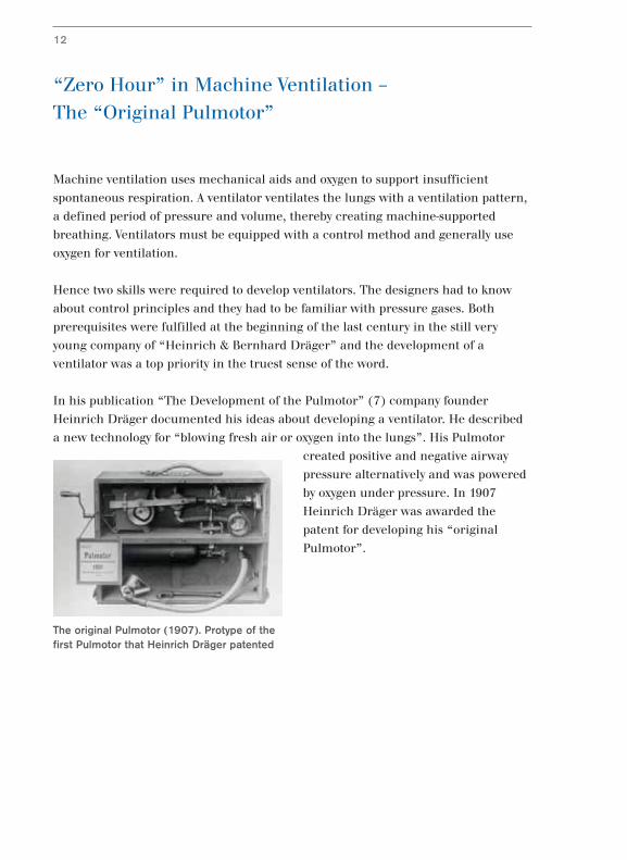
In his publication “The Development of the Pulmotor” (7) company founder
Heinrich Dräger documented his ideas about developing a ventilator. He described
a new technology for “blowing fresh air or oxygen into the lungs”. His Pulmotor
created positive and negative airway
pressure alternatively and was powered
by oxygen under pressure. In 1907
Heinrich Dräger was awarded the
patent for developing his “original
Pulmotor”.
12
The original Pulmotor (1907). Protype of thefirst Pulmotor that Heinrich Dräger patented
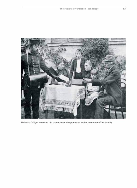
Heinrich Dräger receives his patent from the postman in the presence of his family
The History of Ventilation Technology 13
The Control Principle of the Original Pulmotor
To switch between inhalation and exhalation, Heinrich Dräger used a mechanism
in his original Pulmotor that he was very familiar with from his work as a skilled
watchmaker. The ventilation pattern was controlled with a modified movement
with a cam disc.
It is remarkable that Heinrich Dräger
choose this control principle of the
“Original Pulmotor”. He selected a
technical principle which would replace
nature as closely as possible. By setting
the objective of imitating nature for
artificial respiration, he was way ahead
of his time.
For Heinrich Dräger, the physiological
function that needed to be replaced
was the regular movement of the lungs
with a constant time pattern. Therefore he selected a technical principle for his
ventilator, guaranteeing a constant length of inhalation and exhalation during
artificial ventilation. In modern terms, ventilation was time controlled.
The rest of the world, as well as those who continued to develop the Pulmotor
further, followed another principle. Ventilation patterns were controlled by a
technical principle which switched between inhalation and exhalation when a
certain ventilation pressure was reached. These systems are pressure controlled.
Pressure-controlled ventilation devices became more robust, more reliable and
precise - in short - technically improved. Pressure-controlled ventilation devices seen
from today’s point of view are technically optimized. They followed a path which at
the time was more readily achievable technically.
14
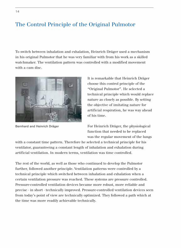
Bernhard and Heinrich Dräger
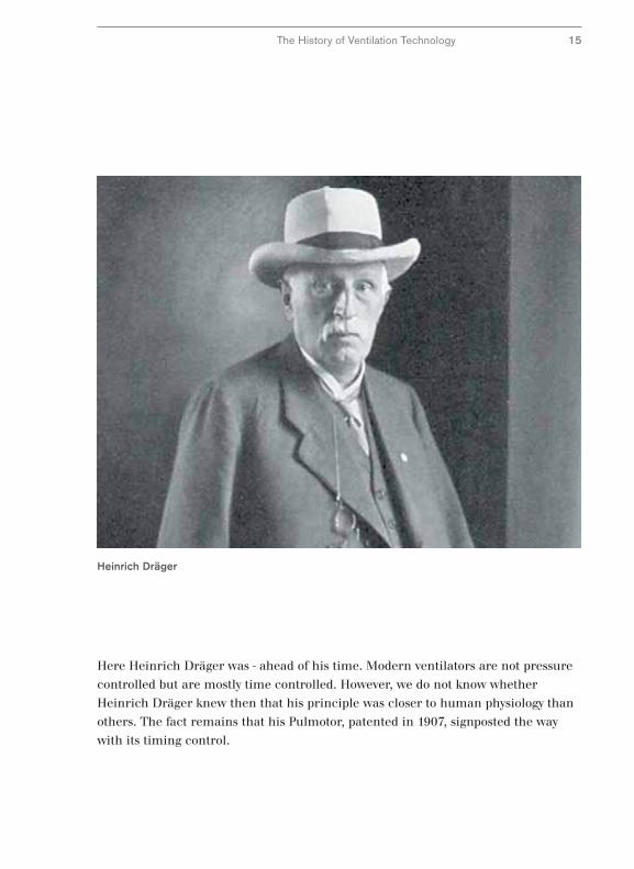
Heinrich Dräger
The History of Ventilation Technology 15
Here Heinrich Dräger was - ahead of his time. Modern ventilators are not pressure
controlled but are mostly time controlled. However, we do not know whether
Heinrich Dräger knew then that his principle was closer to human physiology than
others. The fact remains that his Pulmotor, patented in 1907, signposted the way
with its timing control.
Subsequent Development of the Pulmotor
by Bernhard Dräger
The “Proto-Pulmotor” was certainly a ground-breaking concept but it remained on
the level of a test model that was unsuited for practical use. It had two faults which
Heinrich Dräger recognized and documented during development (7). Firstly his
construction caused considerable re-inhalation of exhaled gas. Secondary the
breathing pattern could not be adapted to the patient due to the inflexible control of
the movement. Heinrich Dräger left it to his son Bernhard and engineer Hans
Schröder to find a remedy for these defects (8).
Bernhard Dräger solved the problem of
re-inhalation of exhaled gas by
redesigning the breathing connecting
apparatus. In the “original Pulmotor”
the patient was connected to the
ventilator only by a tube. This tube
worked to a certain extent as an
extension of the windpipe since the
inhalation and exhalation air was only
separated inside the ventilator.
Bernhard Dräger replaced the connecting
apparatus of the “original Pulmotor” with a tube
system consisting of of an inhalation tube and
exhalation tube. By alterating the valve control, the
patient’s inhaled and exhaled air could be
separated thereby greatly reducing the exhaled
carbon dioxide contamination of the inspiratory
air.
16
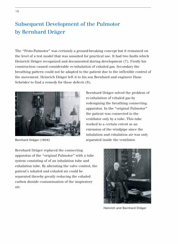
Bernhard Dräger (1904)
Heinrich and Bernhard Dräger
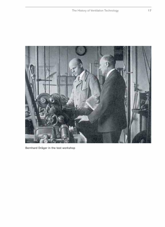
Bernhard Dräger in the test workshop
The History of Ventilation Technology 17
From Prototype to the Production Line –
A New Control Principle
Another great challenge in developing the original Pulmotor was the disadvantage
of the rigid control system which could not be adapted to the patients’ lung
function. Dangerous ventilation pressures could arise, which are caused when
the patient’s lungs are deteriorated. Here the engineer Hans Schröder designed a
construction using a control principle which would be used for several generations
of ventilators. The newly designed control mechanism could be switched
automatically from inhalation to exhalation depending on the pressure in the
airways. A detailed description of the functional principle can be found on the
following double page.
The answer to the question which
ventilator was actually the first depends
on your point of view. If you define a
ventilator as a machine which provides
mechanically-supported breathing
with a defined time pattern and offers
the possibility of ventilation using
oxygen, then Heinrich Dräger
patented Pulmotor was probably the
first in 1907.
However, if you add the criteria of readiness for
production and proven success in clinical use,
then the development of the Pulmotor by Bernhart
Dräger and Hans Schröder should be considered as
the “first ventilator”. From this point of view the
pressure-controlled Pulmotor was almost certainly
the first ventilator worldwide in the history of
medicine.
18
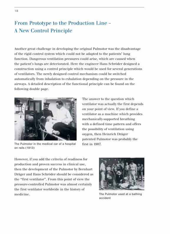
The Pulmotor in the medical car of a hospitalon rails (1913)
The Pulmotor used at a bathingaccident
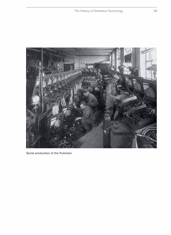
Serial production of the Pulmotor
The History of Ventilation Technology 19
The Pulmotor Principle (1)
The Pulmotor was described in rough detail on the previous pages. Now follows
more detailed description of the structure and function. The technical innovations
of the Pulmotor are the “pressure and suction nozzle” to create the ventilation
pressure and the control mechanism for switching between the inhalation and
exhalation phases.
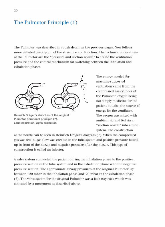
The energy needed for
machine-supported
ventilation came from the
compressed gas cylinder of
the Pulmotor, oxygen being
not simply medicine for the
patient but also the source of
energy for the ventilator.
The oxygen was mixed with
ambient air and fed via a
“suction nozzle” into a tube
system. The construction
of the nozzle can be seen in Heinrich Dräger’s diagram (7). When the compressed
gas was fed in, gas flow was created in the tube system and positive pressure builds
up in front of the nozzle and negative pressure after the nozzle. This type of
construction is called an injector.
A valve system connected the patient during the inhalation phase to the positive
pressure section in the tube system and in the exhalation phase with the negative
pressure section. The approximate airway pressures of the original Pulmotor lay
between +20 mbar in the inhalation phase and -20 mbar in the exhalation phase
(7). The valve system for the original Pulmotor was a four-way cock which was
activated by a movement as described above.
20
Heinrich Dräger’s sketches of the originalPulmotor perational principle (7).Left: Inspiration, right: expiration
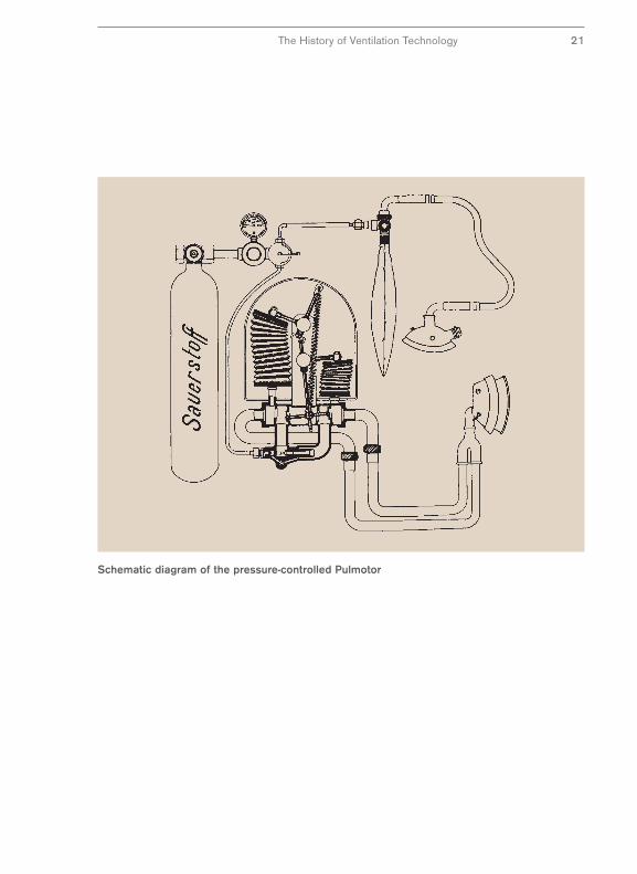
Schematic diagram of the pressure-controlled Pulmotor
The History of Ventilation Technology 21
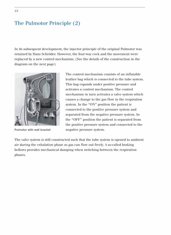
The Pulmotor Principle (2)
In its subsequent development, the injector principle of the original Pulmotor was
retained by Hans Schröder. However, the four-way cock and the movement were
replaced by a new control mechanism. (See the details of the construction in the
diagram on the next page)
The control mechanism consists of an inflatable
leather bag which is connected to the tube system.
This bag expands under positive pressure and
activates a control mechanism. The control
mechanism in turn activates a valve system which
causes a change to the gas flow in the respiration
system. In the “ON” position the patient is
connected to the positive pressure system and
separated from the negative pressure system. In
the “OFF” position the patient is separated from
the positive pressure system and connected to the
negative pressure system.
The valve system is still constructed such that the tube system is opened to ambient
air during the exhalation phase so gas can flow out freely. A so-called braking
bellows provides mechanical damping when switching between the respiration
phases.
22
Pulmotor with wall bracket
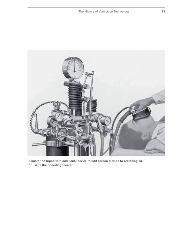
Pulmotor on tripod with additional device to add carbon dioxide to breathing airfor use in the operating theater
The History of Ventilation Technology 23
The Pulmotor Dispute (1)
Only five years after the start of production in 1908, 3,000 Pulmotors were in use –
an enormous number at that time (22). Ten years later, the number of Pulmotors
had doubled to almost 6,000 (12) and after 38 years the number was estimated at
more than 12,000 (16). The resuscitations performed with the Pulmotor were
documented with meticulous exactitude by Drägerwerk and published with great
pride in the Dräger magazines (15).
There was a very obvious interest behind this
publicity activity by Dräger. They wanted to prove to
the public that resuscitation via machine-supported
respiration was superior to a manual method.
They defended themselves against criticism of the
principle of high pressure respiration used in the
Pulmotor, a criticism which was levied by clinical
users in the 1920s and came to a climax in the so-
called “Pulmotor dispute” (13,14,16).
A Pulmotor, at the time, worked with a ventilation pressure of 20 mm H2O in the
inhalation phase and a negative pressure of -25 mm H2O in the exhalation phase.
To stimulate the respiratory center an admixture of CO2 was used. This meant that,
with the exception of the ventilation pressure in the inhalation phase, ventilation at
the time differed considerably from methods today and the criticism of the clinic is
at least understandable from today’s point of view. But the interesting thing is that
the dispute concentrated mainly on the supposedly
dangerous effects of the ventilation pressure on
heart and lungs – the much more questionable
negative pressures or the CO2 admixture, as we
know today, attracted very little interest.
24
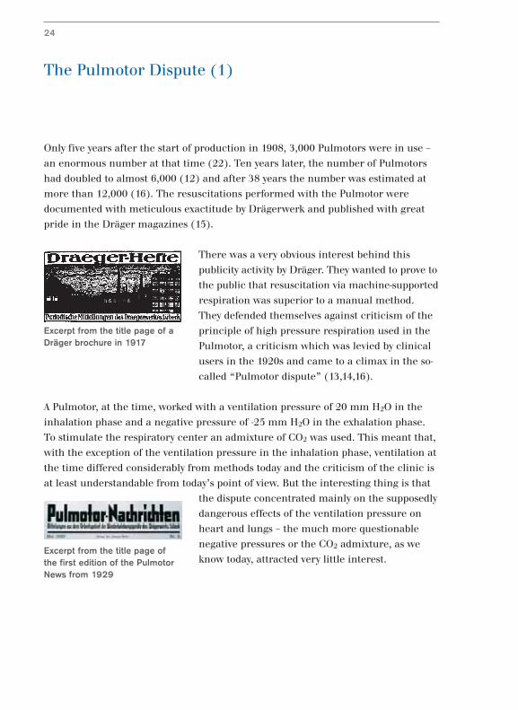
Excerpt from the title page of the first edition of the PulmotorNews from 1929
Excerpt from the title page of aDräger brochure in 1917
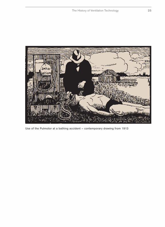
Use of the Pulmotor at a bathing accident – contemporary drawing from 1913
The History of Ventilation Technology 25
The Pulmotor Dispute (2)
In 1922, the Department of Health as the then regulatory agency took the decision,
based on the available knowledge, that there were no objections on health grounds
to the application of positive pressure ventilation. However, it commissioned
scientific investigations into the objections raised. As we know, these investigations
into the subject of “Damage to the organism from ventilators” have not come to a
conclusion even today – so the “Pulmotor Dispute” is actually still relevant and the
jury is still out.
But the Pulmotor dispute is
interesting not only from the
historical point of view.
Another factor adds to the
interest, namely, the tactical
and strategic behavior of
Dräger in the Pulmotor
dispute.
In the Dräger magazines of the period (12,13,14), we can read about the efforts
Dräger undertook to dispel doubts about the efficacy of the Pulmotor and to counter
conjectures about possible hazards. These efforts went far beyond simple commercial
interests. The company wished to prove that they were doing the right thing.
26
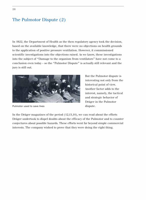
Pulmotor used to save lives
So it was not just an issue of a product image, but rather a question of the company’s
good name. This was defended against all parties; customers, associations,
regulatory agencies, and where appropriate, factual criticism was used as the
impetus to technical development.
This strategy was more than “merchandising” as it was called at the time, today we
would call it marketing.
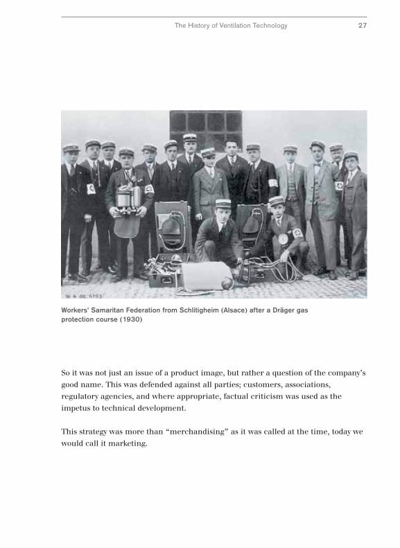
Workers’ Samaritan Federation from Schlitigheim (Alsace) after a Dräger gasprotection course (1930)
The History of Ventilation Technology 27
Further Development of the Pulmotor –
The Pulmotor Canister
The Pulmotor principle with the switching mechanism using a bag, changed
fundamentally in 1955 (11). Instead of controlling the breathing pattern via the
double inflatable bag mechanism, a more manageable, smaller mechanism was
introduced which was called the “Pulmotor canister” because of its casing.
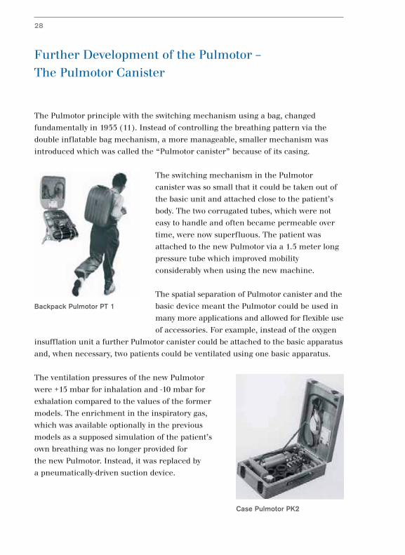
The switching mechanism in the Pulmotor
canister was so small that it could be taken out of
the basic unit and attached close to the patient’s
body. The two corrugated tubes, which were not
easy to handle and often became permeable over
time, were now superfluous. The patient was
attached to the new Pulmotor via a 1.5 meter long
pressure tube which improved mobility
considerably when using the new machine.
The spatial separation of Pulmotor canister and the
basic device meant the Pulmotor could be used in
many more applications and allowed for flexible use
of accessories. For example, instead of the oxygen
insufflation unit a further Pulmotor canister could be attached to the basic apparatus
and, when necessary, two patients could be ventilated using one basic apparatus.
The ventilation pressures of the new Pulmotor
were +15 mbar for inhalation and -10 mbar for
exhalation compared to the values of the former
models. The enrichment in the inspiratory gas,
which was available optionally in the previous
models as a supposed simulation of the patient’s
own breathing was no longer provided for
the new Pulmotor. Instead, it was replaced by
a pneumatically-driven suction device.
28
Backpack Pulmotor PT 1
Case Pulmotor PK2
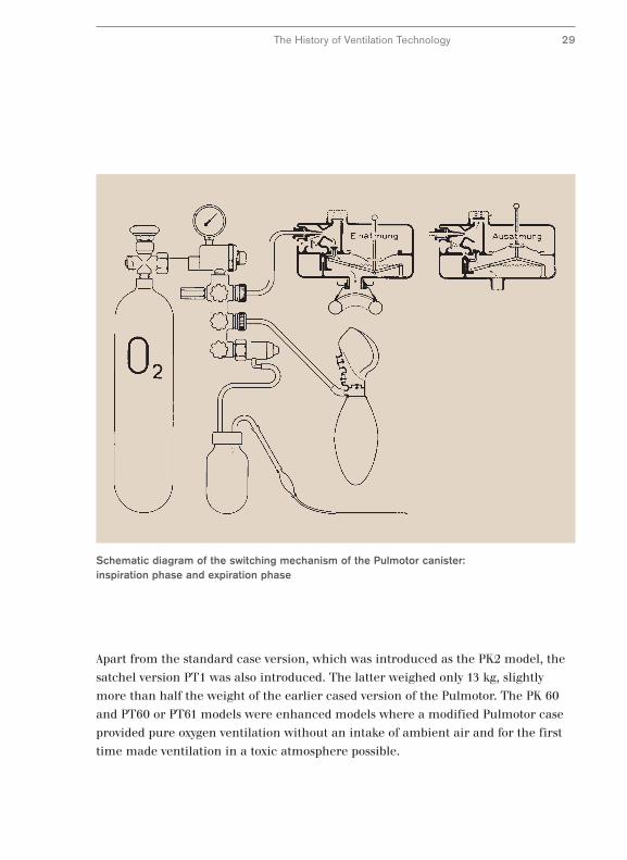
Schematic diagram of the switching mechanism of the Pulmotor canister:inspiration phase and expiration phase
The History of Ventilation Technology 29
Apart from the standard case version, which was introduced as the PK2 model, the
satchel version PT1 was also introduced. The latter weighed only 13 kg, slightly
more than half the weight of the earlier cased version of the Pulmotor. The PK 60
and PT60 or PT61 models were enhanced models where a modified Pulmotor case
provided pure oxygen ventilation without an intake of ambient air and for the first
time made ventilation in a toxic atmosphere possible.
The Pulmotor in Clinical Applications
For several decades the Pulmotor was an independent product series. Its main area
of application was emergency resuscitation. In addition, the Pulmotor principle was
used in various ventilation devices, mostly under another name.
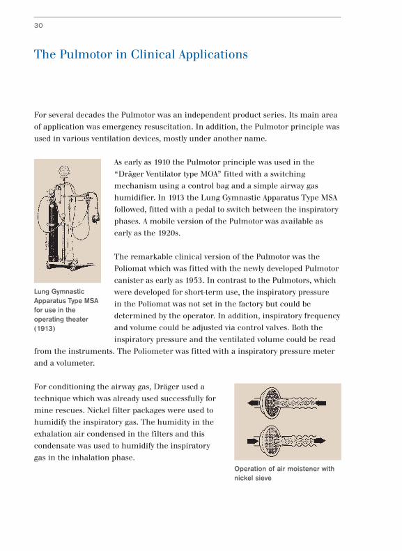
As early as 1910 the Pulmotor principle was used in the
“Dräger Ventilator type MOA” fitted with a switching
mechanism using a control bag and a simple airway gas
humidifier. In 1913 the Lung Gymnastic Apparatus Type MSA
followed, fitted with a pedal to switch between the inspiratory
phases. A mobile version of the Pulmotor was available as
early as the 1920s.
The remarkable clinical version of the Pulmotor was the
Poliomat which was fitted with the newly developed Pulmotor
canister as early as 1953. In contrast to the Pulmotors, which
were developed for short-term use, the inspiratory pressure
in the Poliomat was not set in the factory but could be
determined by the operator. In addition, inspiratory frequency
and volume could be adjusted via control valves. Both the
inspiratory pressure and the ventilated volume could be read
from the instruments. The Poliometer was fitted with a inspiratory pressure meter
and a volumeter.
For conditioning the airway gas, Dräger used a
technique which was already used successfully for
mine rescues. Nickel filter packages were used to
humidify the inspiratory gas. The humidity in the
exhalation air condensed in the filters and this
condensate was used to humidify the inspiratory
gas in the inhalation phase.
30
Lung GymnasticApparatus Type MSAfor use in theoperating theater(1913)
Operation of air moistener withnickel sieve
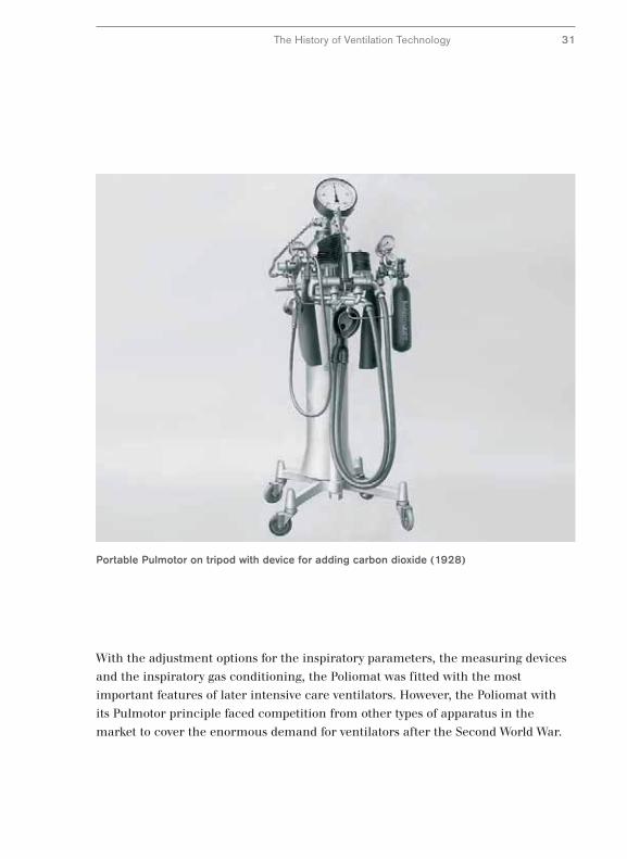
Portable Pulmotor on tripod with device for adding carbon dioxide (1928)
The History of Ventilation Technology 31
With the adjustment options for the inspiratory parameters, the measuring devices
and the inspiratory gas conditioning, the Poliomat was fitted with the most
important features of later intensive care ventilators. However, the Poliomat with
its Pulmotor principle faced competition from other types of apparatus in the
market to cover the enormous demand for ventilators after the Second World War.
A New Way –
Alternating Pressure Ventilation with the Iron Lung
The great demand for ventilators for clinical applications was caused primarily by
the enormous increase in patients needing ventilation following the polio epidemics.
The period shortly after the Second World War in particular saw a rise in the
demand for ventilators which could ventilate patients over longer periods of time
and in some cases were needed for lifelong use. Various devices for this application
were developed which technically and operationally differed more or less from the
Pulmotor.
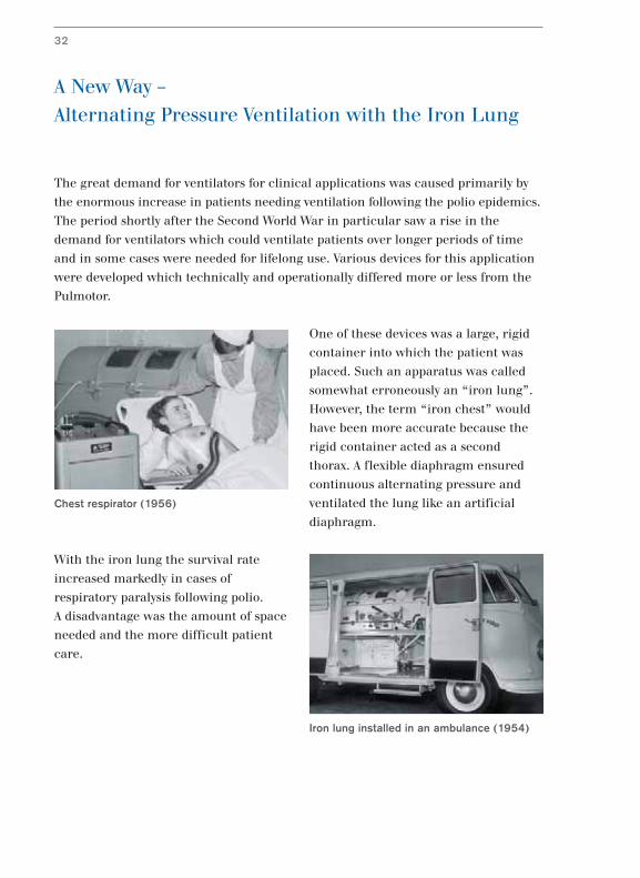
One of these devices was a large, rigid
container into which the patient was
placed. Such an apparatus was called
somewhat erroneously an “iron lung”.
However, the term “iron chest” would
have been more accurate because the
rigid container acted as a second
thorax. A flexible diaphragm ensured
continuous alternating pressure and
ventilated the lung like an artificial
diaphragm.
With the iron lung the survival rate
increased markedly in cases of
respiratory paralysis following polio.
A disadvantage was the amount of space
needed and the more difficult patient
care.
32
Chest respirator (1956)
Iron lung installed in an ambulance (1954)
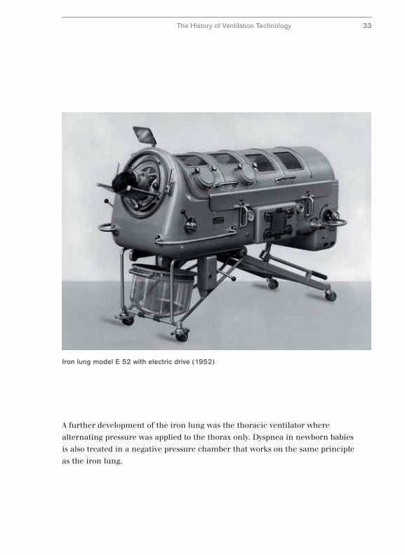
Iron lung model E 52 with electric drive (1952)
The History of Ventilation Technology 33
A further development of the iron lung was the thoracic ventilator where
alternating pressure was applied to the thorax only. Dyspnea in newborn babies
is also treated in a negative pressure chamber that works on the same principle
as the iron lung.
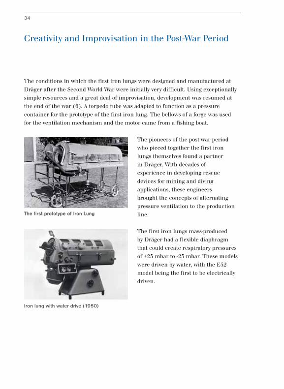
Creativity and Improvisation in the Post-War Period
The conditions in which the first iron lungs were designed and manufactured at
Dräger after the Second World War were initially very difficult. Using exceptionally
simple resources and a great deal of improvisation, development was resumed at
the end of the war (6). A torpedo tube was adapted to function as a pressure
container for the prototype of the first iron lung. The bellows of a forge was used
for the ventilation mechanism and the motor came from a fishing boat.
The pioneers of the post-war period
who pieced together the first iron
lungs themselves found a partner
in Dräger. With decades of
experience in developing rescue
devices for mining and diving
applications, these engineers
brought the concepts of alternating
pressure ventilation to the production
line.
The first iron lungs mass-produced
by Dräger had a flexible diaphragm
that could create respiratory pressures
of +25 mbar to -25 mbar. These models
were driven by water, with the E52
model being the first to be electrically
driven.
34
Iron lung with water drive (1950)
The first prototype of Iron Lung
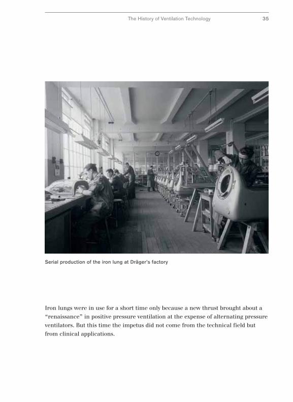
Serial production of the iron lung at Dräger’s factory
The History of Ventilation Technology 35
Iron lungs were in use for a short time only because a new thrust brought about a
“renaissance” in positive pressure ventilation at the expense of alternating pressure
ventilators. But this time the impetus did not come from the technical field but
from clinical applications.
The Beginning of Intensive Care Ventilation –
Assistors
In the 1950s, a new perception in clinical investigation brought about a new
attitude in ventilation therapy. Faulty treatment and complications were frequently
caused because medical staff had to rely more on subjective clinical impressions
when assessing ventilation rather than exact measuring parameters (5).
Without knowing the exact respiratory volumes administered, the set volumes could
injure patients. Either patients suffered from inspiratory gas insufficiency or they
were exposed to high stress by unnecessary intensive care ventilation.
New findings, in particular from
Scandinavia, led to positive pressure
ventilation with its superior ventilation
control becoming important once
more. Two lines of thought were
followed: Firstly the volume of
inspiratory gas was monitored in
pressure regulated ventilation.
Secondly a constant preset breath
volume was applied.
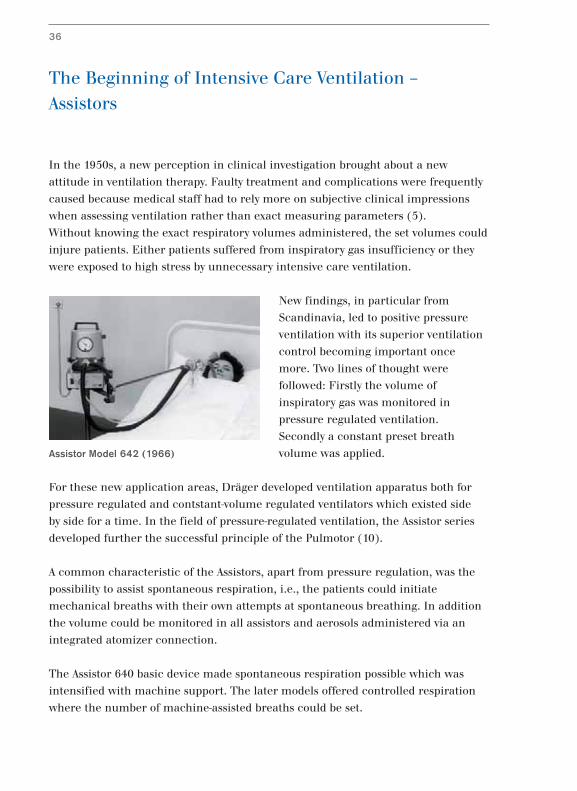
For these new application areas, Dräger developed ventilation apparatus both for
pressure regulated and contstant-volume regulated ventilators which existed side
by side for a time. In the field of pressure-regulated ventilation, the Assistor series
developed further the successful principle of the Pulmotor (10).
A common characteristic of the Assistors, apart from pressure regulation, was the
possibility to assist spontaneous respiration, i.e., the patients could initiate
mechanical breaths with their own attempts at spontaneous breathing. In addition
the volume could be monitored in all assistors and aerosols administered via an
integrated atomizer connection.
The Assistor 640 basic device made spontaneous respiration possible which was
intensified with machine support. The later models offered controlled respiration
where the number of machine-assisted breaths could be set.
36
Assistor Model 642 (1966)
1960 1965 1970
Assistor744
Assistor644
Assistor642
Assistor641
Assistor640
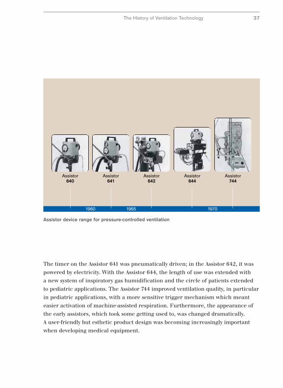
Assistor device range for pressure-controlled ventilation
The History of Ventilation Technology 37
The timer on the Assistor 641 was pneumatically driven; in the Assistor 642, it was
powered by electricity. With the Assistor 644, the length of use was extended with
a new system of inspiratory gas humidification and the circle of patients extended
to pediatric applications. The Assistor 744 improved ventilation quality, in particular
in pediatric applications, with a more sensitive trigger mechanism which meant
easier activation of machine-assisted respiration. Furthermore, the appearance of
the early assistors, which took some getting used to, was changed dramatically.
A user-friendly but esthetic product design was becoming increasingly important
when developing medical equipment.
The Road to Modern Intensive Care Ventilation
The assistors extended the area of application of ventilation considerably. In
addition to ventilation for polio patients, post-operative ventilation and inhalation
therapy for chronic lung disease became common. Despite the expansion of the
range of applications, machine-assisted ventilation remained a relatively simple
measure.
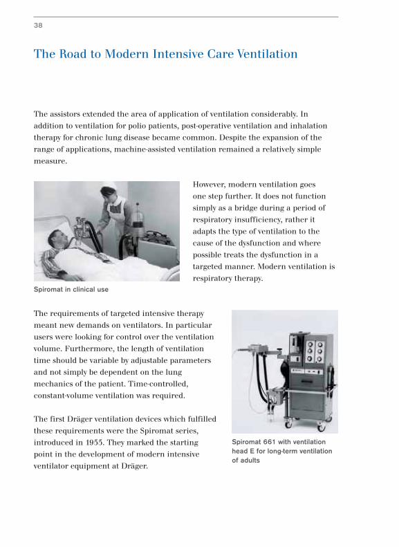
However, modern ventilation goes
one step further. It does not function
simply as a bridge during a period of
respiratory insufficiency, rather it
adapts the type of ventilation to the
cause of the dysfunction and where
possible treats the dysfunction in a
targeted manner. Modern ventilation is
respiratory therapy.
The requirements of targeted intensive therapy
meant new demands on ventilators. In particular
users were looking for control over the ventilation
volume. Furthermore, the length of ventilation
time should be variable by adjustable parameters
and not simply be dependent on the lung
mechanics of the patient. Time-controlled,
constant-volume ventilation was required.
The first Dräger ventilation devices which fulfilled
these requirements were the Spiromat series,
introduced in 1955. They marked the starting
point in the development of modern intensive
ventilator equipment at Dräger.
Spiromat 661 with ventilationhead E for long-term ventilationof adults
38
Spiromat in clinical use
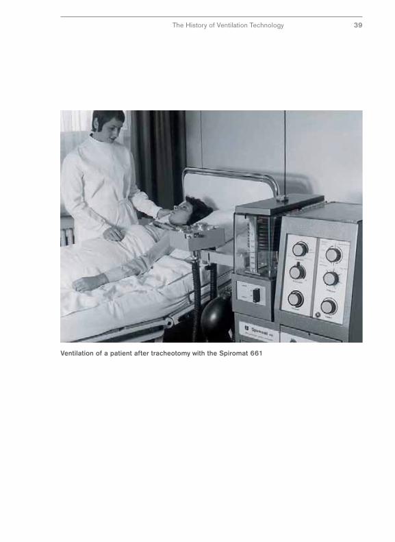
Ventilation of a patient after tracheotomy with the Spiromat 661
The History of Ventilation Technology 39
Constant Progress in Intensive Care Ventilation –
From the Spiromat to the EV-A
The next generation of ventilators were the UV-1 “Universal Ventilator” introduced
in 1977 and the UV-2. They adopted conventional bag ventilation from the Spiromat,
whereby the inspiratory gas is sucked out of a bag and pressed into the lungs.
Control and monitoring of these devices was already performed electronically.
In 1982 the EV-A “Electronic Ventilator” introduced a completely new valve
technology to Dräger ventilators. Electromagnetically actuated valves allowed the
inspiratory gas flow and the inspiratory pressure to be controlled precisely and
rapidly even during a breath. Microcomputers were able to create respiratory
patterns which were unthinkable with the previous generation of equipment.
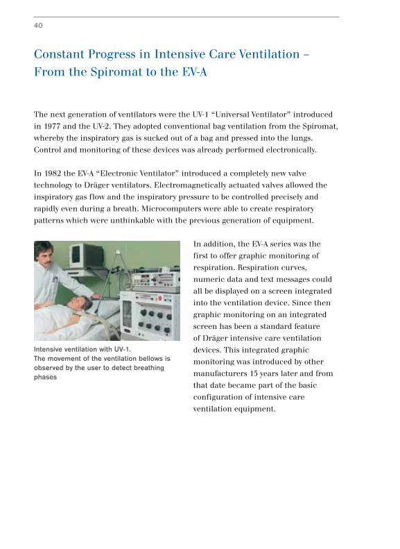
In addition, the EV-A series was the
first to offer graphic monitoring of
respiration. Respiration curves,
numeric data and text messages could
all be displayed on a screen integrated
into the ventilation device. Since then
graphic monitoring on an integrated
screen has been a standard feature
of Dräger intensive care ventilation
devices. This integrated graphic
monitoring was introduced by other
manufacturers 15 years later and from
that date became part of the basic
configuration of intensive care
ventilation equipment.
40
Intensive ventilation with UV-1. The movement of the ventilation bellows isobserved by the user to detect breathingphases
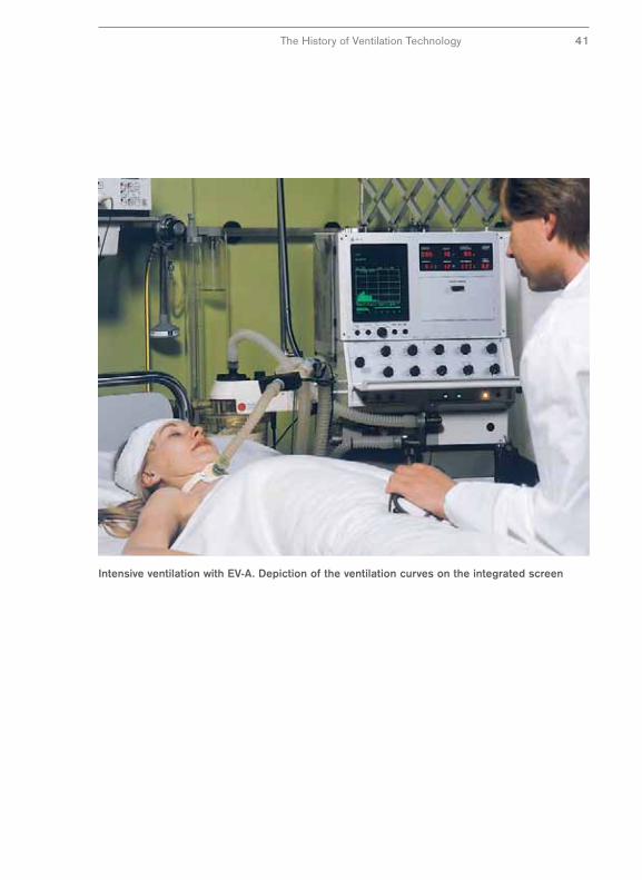
Intensive ventilation with EV-A. Depiction of the ventilation curves on the integrated screen
The History of Ventilation Technology 41
Modern Intensive Care Ventilation –
The Evita Series
The introduction of the Evita series in 1985 saw further developments in computer
technology applied to ventilation and enabled machine-assisted ventilation to be
adapted even closer to spontaneous respiration. New performance characteristics of
the Evita series were made possible by the rapid development of screen technology.
Higher graphics resolution and color displays ensured improved information
transfer via image and text. And progress in screen technology was not limited to
displays. The Evita 4 used a touch-sensitive screen for the first time when it was
introduced in 1995. This touch screen technology practically revolutionized the
concept of functionality in ventilation terms.
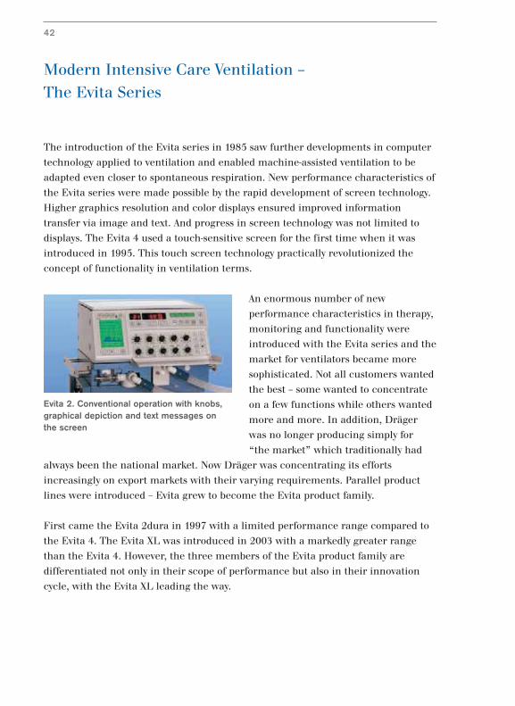
An enormous number of new
performance characteristics in therapy,
monitoring and functionality were
introduced with the Evita series and the
market for ventilators became more
sophisticated. Not all customers wanted
the best – some wanted to concentrate
on a few functions while others wanted
more and more. In addition, Dräger
was no longer producing simply for
“the market” which traditionally had
always been the national market. Now Dräger was concentrating its efforts
increasingly on export markets with their varying requirements. Parallel product
lines were introduced – Evita grew to become the Evita product family.
First came the Evita 2dura in 1997 with a limited performance range compared to
the Evita 4. The Evita XL was introduced in 2003 with a markedly greater range
than the Evita 4. However, the three members of the Evita product family are
differentiated not only in their scope of performance but also in their innovation
cycle, with the Evita XL leading the way.
42
Evita 2. Conventional operation with knobs,graphical depiction and text messages onthe screen
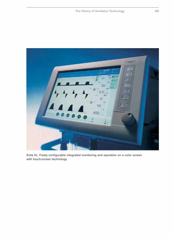
Evita XL. Freely configurable integrated monitoring and operation on a color screenwith touch-screen technology
The History of Ventilation Technology 43
New Markets and New Areas of Application
for Ventilation
Parallel to the Evita series, a range of ventilation devices was developed at the end
of the previous century where costly inhalation valves were replaced with an
alternative robust technology to service the needs of developing and emerging
countries. Instead of the expensive technology of electromagnetically actuated valves
which require good quality pressure gas for their operation, a turbine was used
which only requires ambient air to function. The Savina was introduced in 2000 as
the first Dräger ventilator to use this turbine technology.
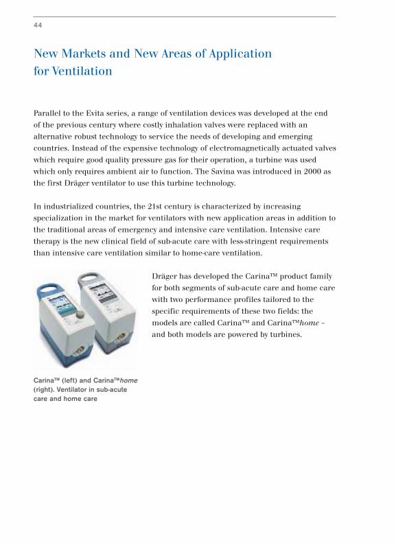
In industrialized countries, the 21st century is characterized by increasing
specialization in the market for ventilators with new application areas in addition to
the traditional areas of emergency and intensive care ventilation. Intensive care
therapy is the new clinical field of sub-acute care with less-stringent requirements
than intensive care ventilation similar to home-care ventilation.
Dräger has developed the Carina™ product family
for both segments of sub-acute care and home care
with two performance profiles tailored to the
specific requirements of these two fields: the
models are called Carina™ and Carina™home –
and both models are powered by turbines.
44
Carina™ (left) and Carina™home(right). Ventilator in sub-acutecare and home care
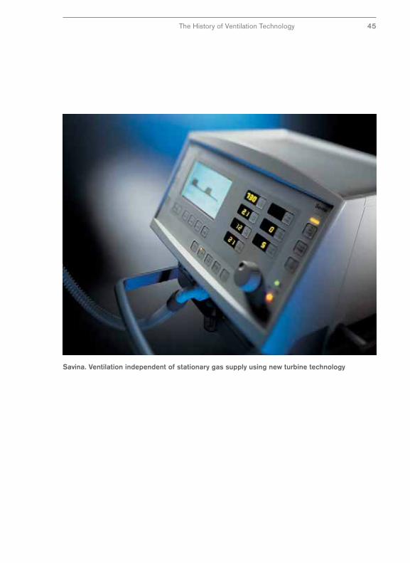
Savina. Ventilation independent of stationary gas supply using new turbine technology
The History of Ventilation Technology 45
Ventilating Small Patients –
The Road to Babylog
Ventilating infants and newborn babies makes special demands on ventilation
technology which cannot be met partially by equipment designed for adults. The
specific challenges of neonatal ventilation are smaller inspiratory volumes, faster
changes in the gas flow and more particularly protection against too high airway
pressures and too large mandatory breath volumes. Initially neonatal ventilators
were simply modified adult ventilators.
The first Dräger ventilator for infants was the Baby Pulmotor, a modification of the
original Pulmotor (23). The respiratory phases were switched via a four-way valve
which was not triggered by a movement but manually. The subsequent generations
of the Pulmotor pediatric versions were developed primarily for first aid in delivery
rooms.
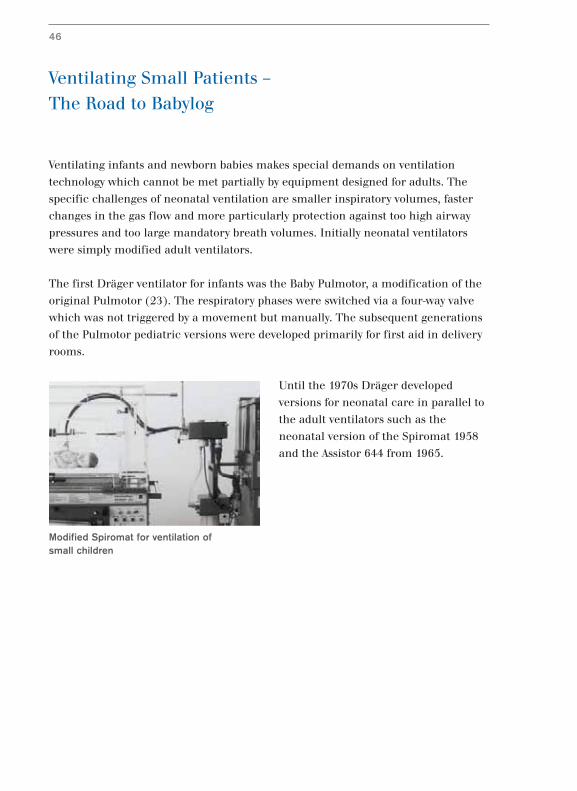
Until the 1970s Dräger developed
versions for neonatal care in parallel to
the adult ventilators such as the
neonatal version of the Spiromat 1958
and the Assistor 644 from 1965.
Modified Spiromat for ventilation of small children
46
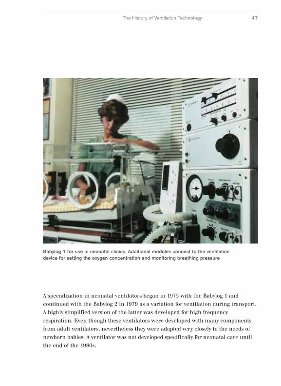
Babylog 1 for use in neonatal clinics. Additional modules connect to the ventilationdevice for setting the oxygen concentration and monitoring breathing pressure
The History of Ventilation Technology 47
A specialization in neonatal ventilators began in 1975 with the Babylog 1 and
continued with the Babylog 2 in 1979 as a variation for ventilation during transport.
A highly simplified version of the latter was developed for high frequency
respiration. Even though these ventilators were developed with many components
from adult ventilators, nevertheless they were adapted very closely to the needs of
newborn babies. A ventilator was not developed specifically for neonatal care until
the end of the 1980s.
Intensive Care Ventilation in Neonatal Care –
The Babylog 8000
The first ventilator designed exclusively for pediatric and neonatal care was the
Babylog 8000, introduced in 1980. Almost everything was new in this product in
comparison to earlier devices. Instead of a valve for dosing a type of gas, the gas was
delivered via numerous digitally-activated valves. This meant that very rapid
changes in gas flow and the high dynamic range typical of neonatal ventilation
could be achieved.
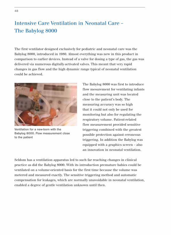
The Babylog 8000 was first to introduce
flow mesurement for ventilating infants
and the measuring unit was located
close to the patient’s body. The
measuring accuracy was so high
that it could not only be used for
monitoring but also for regulating the
respiratory volume. Patient-related
flow measurement provided sensitive
triggering combined with the greatest
possible protection against erroneous
triggering. In addition the Babylog was
equipped with a graphics screen – also
an innovation in neonatal ventilation.
Seldom has a ventilation apparatus led to such far reaching changes in clinical
practice as did the Babylog 8000. With its introduction premature babies could be
ventilated on a volume-oriented basis for the first time because the volume was
metered and measured exactly. The sensitive triggering method and automatic
compensation for leakages, which are normally unavoidable in neonatal ventilation,
enabled a degree of gentle ventilation unknown until then.
48
Ventilation for a new-born with the Babylog 8000. Flow measurement close to the patient
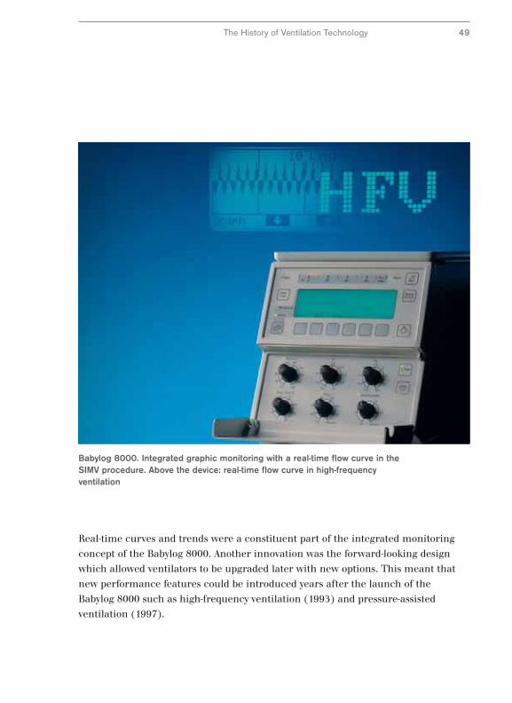
Babylog 8000. Integrated graphic monitoring with a real-time flow curve in theSIMV procedure. Above the device: real-time flow curve in high-frequencyventilation
The History of Ventilation Technology 49
Real-time curves and trends were a constituent part of the integrated monitoring
concept of the Babylog 8000. Another innovation was the forward-looking design
which allowed ventilators to be upgraded later with new options. This meant that
new performance features could be introduced years after the launch of the
Babylog 8000 such as high-frequency ventilation (1993) and pressure-assisted
ventilation (1997).
From the Pulmotor to the Oxylog®
The limits of pressure-assisted ventilation in intensive care ventilation had been
recognized in the 1950s and had led to the development of the time-controlled
constant-volume ventilators. This development did not reach the field of emergency
ventilation until two decades later. At Dräger it led to the development of a
completely new emergency ventilation device launched in 1976 under the name
of Oxylog®.
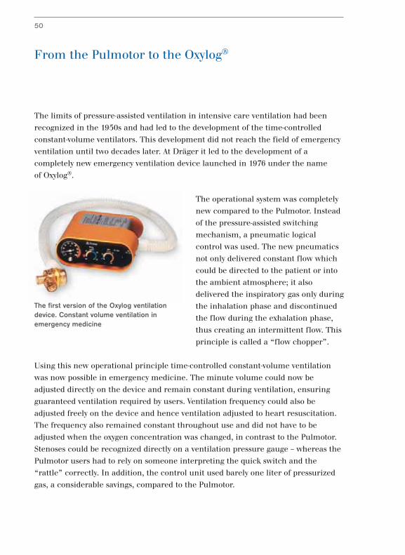
The operational system was completely
new compared to the Pulmotor. Instead
of the pressure-assisted switching
mechanism, a pneumatic logical
control was used. The new pneumatics
not only delivered constant flow which
could be directed to the patient or into
the ambient atmosphere; it also
delivered the inspiratory gas only during
the inhalation phase and discontinued
the flow during the exhalation phase,
thus creating an intermittent flow. This
principle is called a “flow chopper”.
Using this new operational principle time-controlled constant-volume ventilation
was now possible in emergency medicine. The minute volume could now be
adjusted directly on the device and remain constant during ventilation, ensuring
guaranteed ventilation required by users. Ventilation frequency could also be
adjusted freely on the device and hence ventilation adjusted to heart resuscitation.
The frequency also remained constant throughout use and did not have to be
adjusted when the oxygen concentration was changed, in contrast to the Pulmotor.
Stenoses could be recognized directly on a ventilation pressure gauge – whereas the
Pulmotor users had to rely on someone interpreting the quick switch and the
“rattle” correctly. In addition, the control unit used barely one liter of pressurized
gas, a considerable savings, compared to the Pulmotor.
50
The first version of the Oxylog ventilationdevice. Constant volume ventilation inemergency medicine
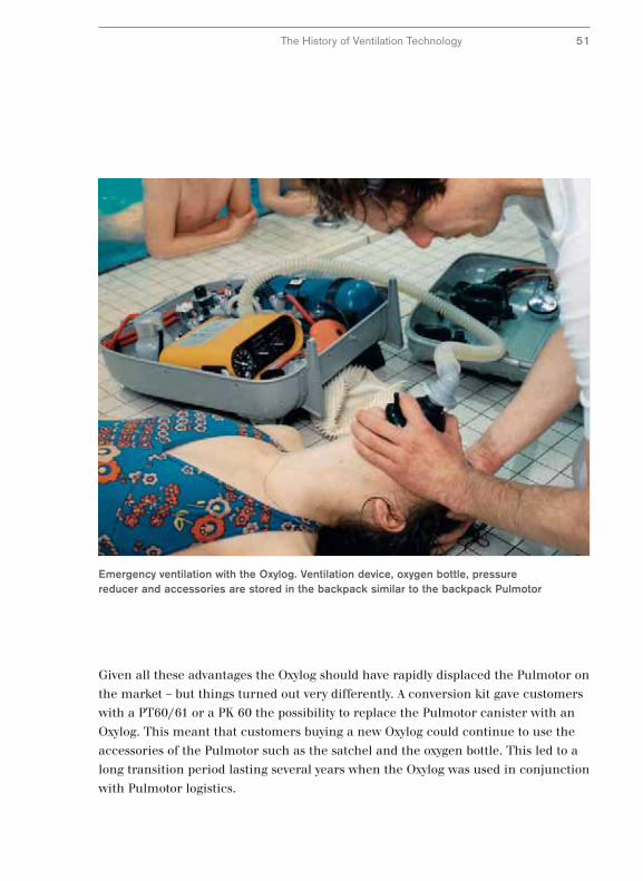
Emergency ventilation with the Oxylog. Ventilation device, oxygen bottle, pressurereducer and accessories are stored in the backpack similar to the backpack Pulmotor
Given all these advantages the Oxylog should have rapidly displaced the Pulmotor on
the market – but things turned out very differently. A conversion kit gave customers
with a PT60/61 or a PK 60 the possibility to replace the Pulmotor canister with an
Oxylog. This meant that customers buying a new Oxylog could continue to use the
accessories of the Pulmotor such as the satchel and the oxygen bottle. This led to a
long transition period lasting several years when the Oxylog was used in conjunction
with Pulmotor logistics.
The History of Ventilation Technology 51
The Oxylog® Series –
The Road to Modern Emergency Ventilation
The Oxylog® was designed for first aid applications and its primary purpose was to
maintain vital functions via machine ventilation. Its application concentrated on
first aid situations and the subsequent transport of patients for treatment in
hospital, so-called primary transport. Therefore the performance features were
limited to purely controlled ventilation and for monitoring, a simple manometer
for measuring the airway pressure was used.
But the requirements for emergency ventilation
increased also and further fields of application for the
Oxylog developed such as the secondary transport or
transport during treatment in hospital, for example
when a patient is moved to another ward. To meet this
need in 1993 the Oxylog 2000 was introduced. This
enabled spontaneous respiration by the patient in
addition to controlled ventilation. It was fitted with
extensive monitoring features for monitoring the
airway pressure and respiratory volume. Readings and
text alerts could be read for the first time in
emergency situations on a screen and alarms alerted personnel to potentially life-
threatening conditions. All settings for the Oxylog 2000 could be made directly on
the basic unit, thus removing the need for separate adjustments of valves.
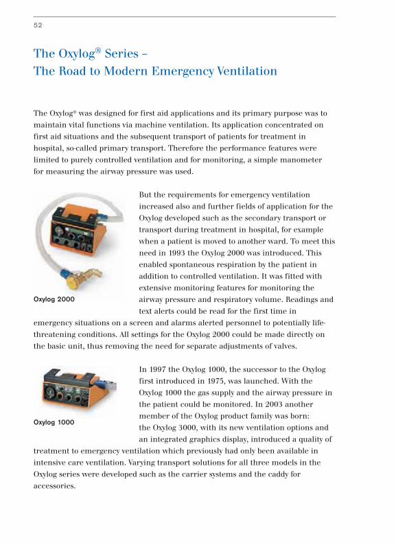
In 1997 the Oxylog 1000, the successor to the Oxylog
first introduced in 1975, was launched. With the
Oxylog 1000 the gas supply and the airway pressure in
the patient could be monitored. In 2003 another
member of the Oxylog product family was born:
the Oxylog 3000, with its new ventilation options and
an integrated graphics display, introduced a quality of
treatment to emergency ventilation which previously had only been available in
intensive care ventilation. Varying transport solutions for all three models in the
Oxylog series were developed such as the carrier systems and the caddy for
accessories.
52
Oxylog 1000
Oxylog 2000
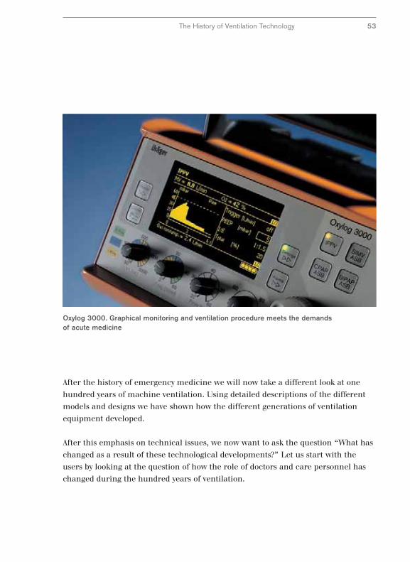
Oxylog 3000. Graphical monitoring and ventilation procedure meets the demandsof acute medicine
After the history of emergency medicine we will now take a different look at one
hundred years of machine ventilation. Using detailed descriptions of the different
models and designs we have shown how the different generations of ventilation
equipment developed.
After this emphasis on technical issues, we now want to ask the question “What has
changed as a result of these technological developments?” Let us start with the
users by looking at the question of how the role of doctors and care personnel has
changed during the hundred years of ventilation.
The History of Ventilation Technology 53
The Role of Medical Staff
In summary, the history of ventilators as described above can be divided roughly
into three phases: Firstly, simple machine ventilation, secondly ventilation
optimized by manual corrections made by medical staff and thirdly, ventilation with
automatic adjustment to the patient.
The Pulmotor, Assistors and the first constant-volume ventilators are simple
machines in today’s understanding. The primary goal of ventilation was to ensure
ventilation of lungs during use. Medical staff had only a few possibilities of adjusting
the machine and only modest safety devices, for example against excessive
ventilation pressure.
With the introduction of the UV-1 the role of medical staff began to change: From
now on they were not only responsible for simply setting the basic parameters, they
could adapt ventilation to the patient in a targeted manner. Furthermore they were
able to prepare the patient for independent respiration by a gradual, conscious
reduction of machine ventilation and hence wean the patient from the machine.
Furthermore they were able to optimize the inspiratory pressure, for example, and
at the same time maintain the volume at a constant level. However, these new
possibilities required a great deal of work in their medical applications which
benefited the patient only in part. A large part of the additional work consisted in
manual corrections of the shortcomings of ventilation technology at the time.
The new possibilities offered by an automatic adjustment of the ventilator to the
physiological condition of the patient started to change the role of clinicians:
They were released from their roles as “machine operators.”
Automatic adaptation to the patient was limited initially to mechanical changes to
the lung: For example, the EV-A was able to ventilate in the case of a fistula, for
example, even when a leak occurred through corresponding control of the
inspiratory gas supply. The Evita model offered improved adaptation of ventilation
to the patient’s breathing by subjugating machine ventilation to physiological
respiration and allowing spontaneous respiration during machine ventilation.
54
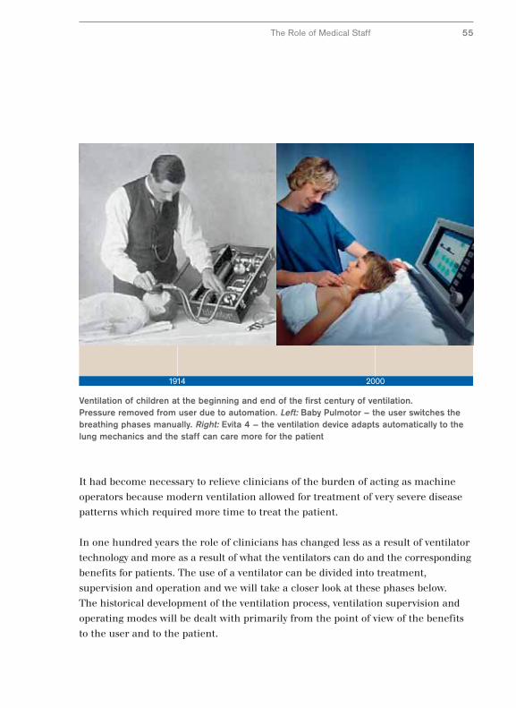
Ventilation of children at the beginning and end of the first century of ventilation.Pressure removed from user due to automation. Left: Baby Pulmotor – the user switches thebreathing phases manually. Right: Evita 4 – the ventilation device adapts automatically to thelung mechanics and the staff can care more for the patient
The Role of Medical Staff 55
It had become necessary to relieve clinicians of the burden of acting as machine
operators because modern ventilation allowed for treatment of very severe disease
patterns which required more time to treat the patient.
In one hundred years the role of clinicians has changed less as a result of ventilator
technology and more as a result of what the ventilators can do and the corresponding
benefits for patients. The use of a ventilator can be divided into treatment,
supervision and operation and we will take a closer look at these phases below.
The historical development of the ventilation process, ventilation supervision and
operating modes will be dealt with primarily from the point of view of the benefits
to the user and to the patient.
1914 2000
The Ventilator in Clinical Applications –
An Overview
In ventilation technology we describe the time constant for pressure and volume as
ventilation patterns. In contrast a ventilation technique describes the interaction
between patient and ventilator. When developing ventilation procedures the initial
emphasis was on short-term airway gas supply when the patient’s breathing
stopped. The first ventilation devices were emergency ventilation devices where a
short-term bridge was the primary concern when the patient’s own breathing
stopped. However, the life-saving ventilation techniques put such a strain on the
lungs when used over time that it was difficult to return patients to normal
respiration.
An adaptation of ventilation techniques to the physiology and less stressful
ventilation was initially achieved using auxiliary devices which limited the
damaging effects of ventilation and trained specialists could use in a targeted
manner. Ventilation techniques which ensure automatic adaptation of ventilation to
the patient have been developed only recently.
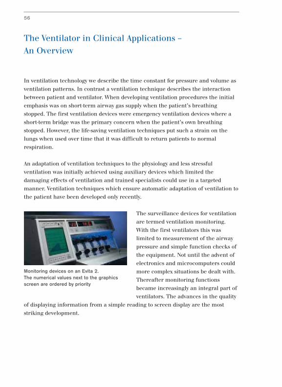
The surveillance devices for ventilation
are termed ventilation monitoring.
With the first ventilators this was
limited to measurement of the airway
pressure and simple function checks of
the equipment. Not until the advent of
electronics and microcomputers could
more complex situations be dealt with.
Thereafter monitoring functions
became increasingly an integral part of
ventilators. The advances in the quality
of displaying information from a simple reading to screen display are the most
striking development.
Monitoring devices on an Evita 2. The numerical values next to the graphicsscreen are ordered by priority
56
Monitoring Userinterface
Ventilation mode
Ventilator
OperationMonitoring Treatment
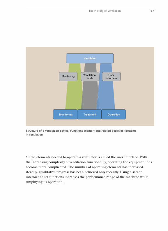
Structure of a ventilation device. Functions (center) and related activities (bottom)in ventilation
All the elements needed to operate a ventilator is called the user interface. With
the increasing complexity of ventilation functionality, operating the equipment has
become more complicated. The number of operating elements has increased
steadily. Qualitative progress has been achieved only recently. Using a screen
interface to set functions increases the performance range of the machine while
simplifying its operation.
The History of Ventilation 57
Respiration and Ventilation Technique –
The Fundamental Difference
For several decades adequate ventilation of the lungs was the primary goal of
ventilation. Not until the 1970s did a change of attitude occur and ventilation
techniques were established based on avoiding damage to lungs. There is a good
reason for the late development of a patient-oriented ventilation. There is a
fundamental difference between machine ventilation and physiological respiration.
Ventilation is not simulation of respiration, rather it is a substitute with unavoidable
side effects due to the principle which people were not aware of earlier. In addition
the activation and adaptation of the inspiratory gas flow in ventilation was a great
technological challenge which was quite simply beyond the capabilities of older
ventilators.
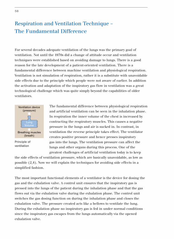
The fundamental difference between physiological respiration
and artificial ventilation can be seen in the inhalation phase.
In respiration the inner volume of the chest is increased by
contracting the respiratory muscles. This causes a negative
pressure in the lungs and air is sucked in. In contrast, in
ventilation the reverse principle takes effect. The ventilator
creates positive pressure and hence presses inspiratory
gas into the lungs. The ventilation pressure can affect the
lungs and other organs during this process. One of the
greatest challenges of artificial ventilation today is to keep
the side effects of ventilation pressure, which are basically unavoidable, as low as
possible (2,4). Now we will explain the techniques for avoiding side effects in a
simplified fashion.
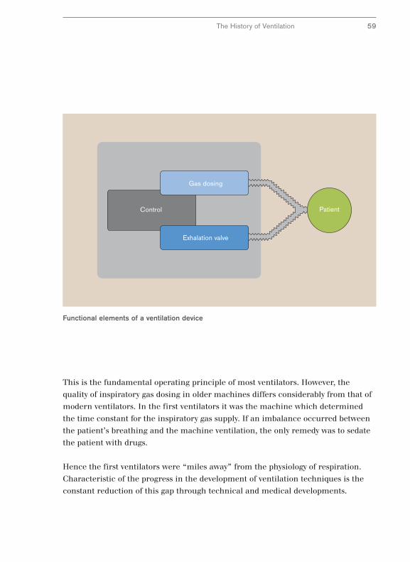
The most important functional elements of a ventilator is the device for dosing the
gas and the exhalation valve. A control unit ensures that the inspiratory gas is
pressed into the lungs of the patient during the inhalation phase and that the gas
flows out via the exhalation valve during the exhalation phase. The control unit
switches the gas dosing function on during the inhalation phase and closes the
exhalation valve. The pressure created acts like a bellows to ventilate the lung.
During the exhalation phase no inspiratory gas is fed in under normal conditions
since the inspiratory gas escapes from the lungs automatically via the opened
exhalation valve.
58
LungVolume
Ventilation device(pressure)
Breathing muscles(breath)
Principle ofventilation
Control
Exhalation valve
Gas dosing
Patient
Functional elements of a ventilation device
The History of Ventilation 59
This is the fundamental operating principle of most ventilators. However, the
quality of inspiratory gas dosing in older machines differs considerably from that of
modern ventilators. In the first ventilators it was the machine which determined
the time constant for the inspiratory gas supply. If an imbalance occurred between
the patient’s breathing and the machine ventilation, the only remedy was to sedate
the patient with drugs.
Hence the first ventilators were “miles away” from the physiology of respiration.
Characteristic of the progress in the development of ventilation techniques is the
constant reduction of this gap through technical and medical developments.
Three Problems of Machine Ventilation
The adaptation of time-controlled machine ventilation to physiological respiration
was not solved in one go but happened in a number of stages. Each stage marked
the solution of one of the problems caused by the reversal of the pressure conditions
and technical limitations.
Here we describe the three main problems which can be identified from the
ventilation pattern. A ventilation pattern can be displayed as ventilation curves.
Such curves are drawn when the airway pressure or the inspiratory gas flow is
recorded for the length of an inhalation or exhalation. The time interval from the
beginning of an inhalation to the start of the next is called the ventilation cycle.
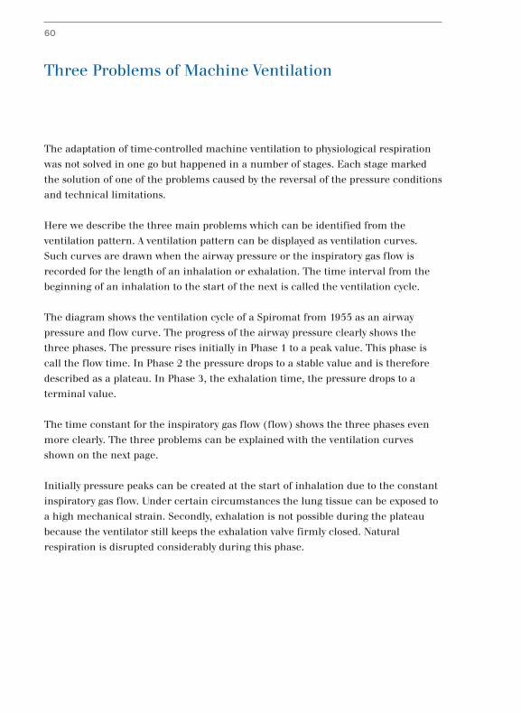
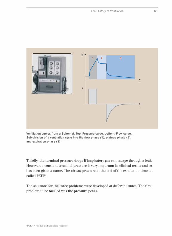
The diagram shows the ventilation cycle of a Spiromat from 1955 as an airway
pressure and flow curve. The progress of the airway pressure clearly shows the
three phases. The pressure rises initially in Phase 1 to a peak value. This phase is
call the flow time. In Phase 2 the pressure drops to a stable value and is therefore
described as a plateau. In Phase 3, the exhalation time, the pressure drops to a
terminal value.
The time constant for the inspiratory gas flow (flow) shows the three phases even
more clearly. The three problems can be explained with the ventilation curves
shown on the next page.
Initially pressure peaks can be created at the start of inhalation due to the constant
inspiratory gas flow. Under certain circumstances the lung tissue can be exposed to
a high mechanical strain. Secondly, exhalation is not possible during the plateau
because the ventilator still keeps the exhalation valve firmly closed. Natural
respiration is disrupted considerably during this phase.
60
t
t
P1 2 3
Ventilation curves from a Spiromat. Top: Pressure curve, bottom: Flow curve. Sub-division of a ventilation cycle into the flow phase (1), plateau phase (2), and expiration phase (3)
The History of Ventilation 61
*PEEP = Positive End Expiratory Pressure
Thirdly, the terminal pressure drops if inspiratory gas can escape through a leak.
However, a constant terminal pressure is very important in clinical terms and so
has been given a name. The airway pressure at the end of the exhalation time is
called PEEP*.
The solutions for the three problems were developed at different times. The first
problem to be tackled was the pressure peaks.
Pressure-Limited Ventilation with the UV-1
Pressure peaks at the beginning of the inhalation phase arise during machine
ventilation as a result of a very simple form of inspiratory gas dosage as used in the
first Spiromats. The inspiratory gas is administered with a constant flow without
taking into account the airway pressure created. This type of ventilation can result
in pressure peaks in the lung due to physical laws. Only when the inspiratory gas
spreads throughout the lungs does the pressure revert to the plateau value.
Anesthetists recognize this problem. They avoid pressure peaks in manual bag
ventilation by skillful control of the ventilation pressure. They carefully manipulate
the ventilation bag to avoid overextending the lungs at any time with too high an
airway pressure. With machine ventilation the problem of pressure peaks was
solved with a technical solution which copies the hand of the experienced
anesthetist to a certain extent. The principle is that of inflatable bag ventilation
with an adjustable working pressure which was used in the UV-1.
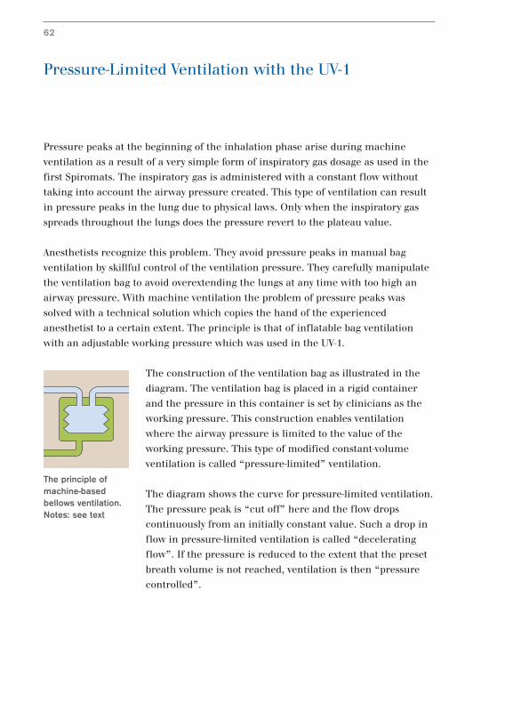
The construction of the ventilation bag as illustrated in the
diagram. The ventilation bag is placed in a rigid container
and the pressure in this container is set by clinicians as the
working pressure. This construction enables ventilation
where the airway pressure is limited to the value of the
working pressure. This type of modified constant-volume
ventilation is called “pressure-limited” ventilation.
The diagram shows the curve for pressure-limited ventilation.
The pressure peak is “cut off” here and the flow drops
continuously from an initially constant value. Such a drop in
flow in pressure-limited ventilation is called “decelerating
flow”. If the pressure is reduced to the extent that the preset
breath volume is not reached, ventilation is then “pressure
controlled”.
62
The principle ofmachine-basedbellows ventilation.Notes: see text
t
t
P1 2 3
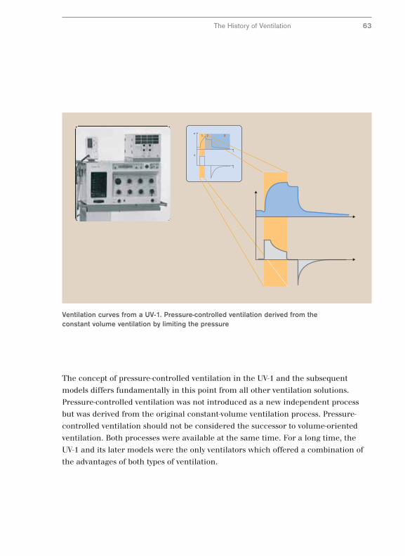
Ventilation curves from a UV-1. Pressure-controlled ventilation derived from theconstant volume ventilation by limiting the pressure
The History of Ventilation 63
The concept of pressure-controlled ventilation in the UV-1 and the subsequent
models differs fundamentally in this point from all other ventilation solutions.
Pressure-controlled ventilation was not introduced as a new independent process
but was derived from the original constant-volume ventilation process. Pressure-
controlled ventilation should not be considered the successor to volume-oriented
ventilation. Both processes were available at the same time. For a long time, the
UV-1 and its later models were the only ventilators which offered a combination of
the advantages of both types of ventilation.
New Ventilation Technology with EV-A
Conventional pressure-controlled ventilation did not made any additional demands
on ventilator technology. It could be carried out with a thoroughly satisfactory
quality with the bag ventilation used earlier.
The bag ventilation principle was superseded in the 1980s by microprocessor
controlled ventilators and Dräger was among the first manufacturers with its EV-A.
Initially the new ventilator generation did not achieve any significant solutions to
the problems of conventional processes but rather copied the established ventilation
types with a new technology for inspiratory gas dosage and control of the exhalation
valve.
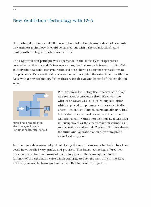
With this new technology the function of the bag
was replaced by modern valves. What was new
with these valves was the electromagnetic drive
which replaced the pneumatically or electrically
driven mechanism. The electormagnetic drive had
been established several decades earlier when it
was first used in ventilation technology. It was used
in loudspeakers as the electromagnets vibrating at
such speed created sound. The next diagram shows
the functional operation of an electromagnetic
valve for dosing gas.
But the new valves were not just fast. Using the new microcomputer technology they
could be controlled very quickly and precisely. This latest technology offered new
dimensions in dynamic dosing of inspiratory gases. The same applied to the
function of the exhalation valve which was triggered for the first time in the EV-A
indirectly via an electromagnet and controlled by a microcomputer.
64
Functional drawing of anelectromagnetic valve. For other notes, refer to text
t
t
P1 2 3
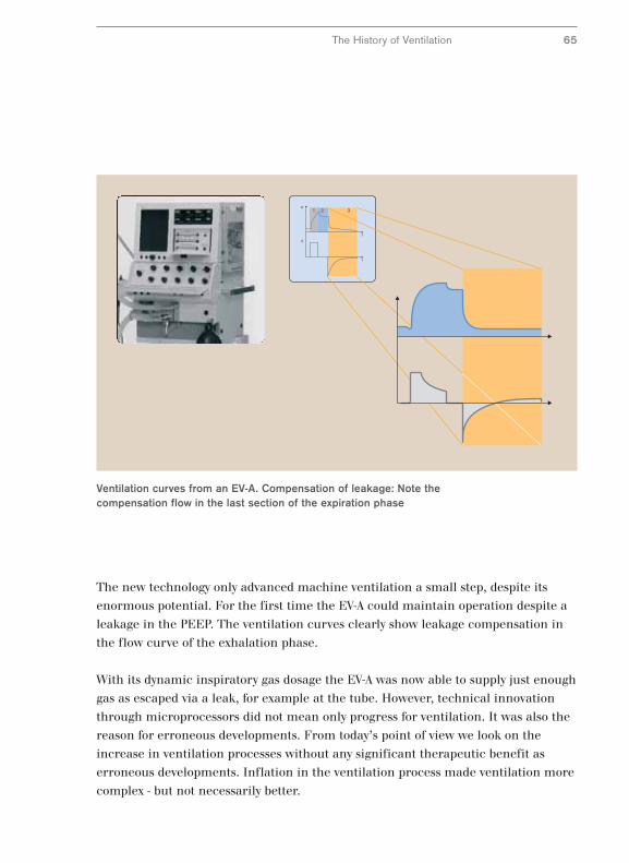
Ventilation curves from an EV-A. Compensation of leakage: Note thecompensation flow in the last section of the expiration phase
The History of Ventilation 65
The new technology only advanced machine ventilation a small step, despite its
enormous potential. For the first time the EV-A could maintain operation despite a
leakage in the PEEP. The ventilation curves clearly show leakage compensation in
the flow curve of the exhalation phase.
With its dynamic inspiratory gas dosage the EV-A was now able to supply just enough
gas as escaped via a leak, for example at the tube. However, technical innovation
through microprocessors did not mean only progress for ventilation. It was also the
reason for erroneous developments. From today’s point of view we look on the
increase in ventilation processes without any significant therapeutic benefit as
erroneous developments. Inflation in the ventilation process made ventilation more
complex - but not necessarily better.
Simple and Open for Spontaneous Respiration –
Pressure Controlled BIPAP*
Not until half a century later would a simplification of machine ventilation come
about with the BIPAP ventilation process (1,3,17). The new process was
characterized by an unusually broad spectrum of applications from pure machine
ventilation to pure spontaneous respiration. Shortly after its publication it was
available for many clinical applications from 1988 on with the first generation of
the Evita series.
The most important advance with the new process was the possibility of spontaneous
respiration during artificial ventilation. This solved the last of the three problems of
machine ventilation described above. Conventional machine ventilation did not
allow spontaneous respiration during mandatory breaths. The patient could not
breathe out during mandatory breaths since the exhalation valve was closed. The
solution was the “Open System” principle which was introduced with the Evita
ventilator.
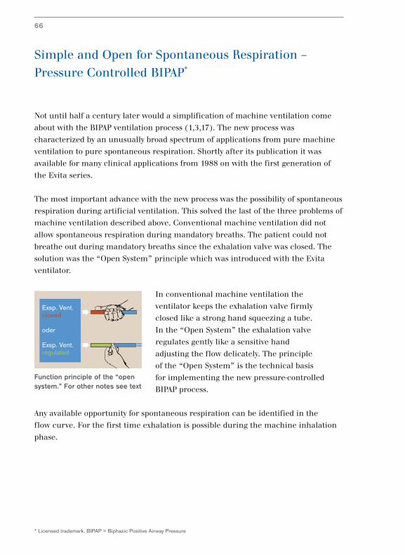
In conventional machine ventilation the
ventilator keeps the exhalation valve firmly
closed like a strong hand squeezing a tube.
In the “Open System” the exhalation valve
regulates gently like a sensitive hand
adjusting the flow delicately. The principle
of the “Open System” is the technical basis
for implementing the new pressure-controlled
BIPAP process.
Any available opportunity for spontaneous respiration can be identified in the
flow curve. For the first time exhalation is possible during the machine inhalation
phase.
66
* Licensed trademark, BIPAP = Biphasic Positive Airway Pressure
Exsp. Vent.closed
oder
Exsp. Vent.regulated
Function principle of the “opensystem.” For other notes see text
t
t
P1 2 3
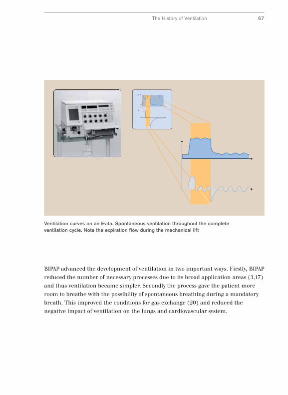
Ventilation curves on an Evita. Spontaneous ventilation throughout the completeventilation cycle. Note the expiration flow during the mechanical lift
The History of Ventilation 67
BIPAP advanced the development of ventilation in two important ways. Firstly, BIPAP
reduced the number of necessary processes due to its broad application areas (3,17)
and thus ventilation became simpler. Secondly the process gave the patient more
room to breathe with the possibility of spontaneous breathing during a mandatory
breath. This improved the conditions for gas exchange (20) and reduced the
negative impact of ventilation on the lungs and cardiovascular system.
The BIPAP process brought pressure-controlled ventilation to an advanced level. It
was several years later before the next significant improvement in volume-constant
ventilation came in 1995 with the introduction of Evita 4.
The problem of pressure peaks in the inhalation phase with constant-volume
ventilation remained unresolved. Although the pressure peaks could be eliminated
with the pressure limitation of the UV-1, they still had to be reset frequently during
the ventilation process. A manually adjusted pressure limitation is only ideal if the
mechanical conditions in the lungs remain unchanged which is normally not the
case with a ventilated lung.
The mechanical properties of the lungs change; they can become more rigid or
more elastic. Their elasticity changes and this is called compliance in respiration
physiology. In addition the flow resistance in the airways can increase or decrease.
The underlying factor is the airway resistance and is called resistance in respiration
physiology.
For example, if compliance in the lungs increases and the lungs become more
elastic during therapy, lower ventilation pressures are sufficient to administer the
required volume. Hence increased compliance requires less pressure for the
required volume to be administered. In fact, the clinicians should measure the
compliance with every breath and then quickly set the lowest possible ventilation
pressure.
68
* Licensed brand
Optimum Pressure and Open for Spontaneous
Respiration – Constant-Volume AutoFlow®*
IPPV123
P
V
t
tTinsp
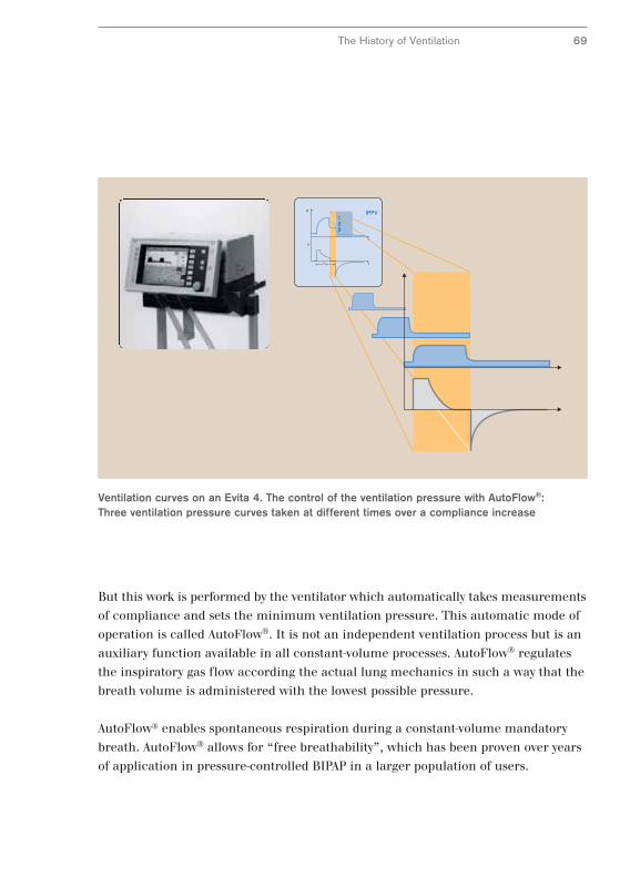
Ventilation curves on an Evita 4. The control of the ventilation pressure with AutoFlow®:Three ventilation pressure curves taken at different times over a compliance increase
The History of Ventilation 69
But this work is performed by the ventilator which automatically takes measurements
of compliance and sets the minimum ventilation pressure. This automatic mode of
operation is called AutoFlow®. It is not an independent ventilation process but is an
auxiliary function available in all constant-volume processes. AutoFlow® regulates
the inspiratory gas flow according the actual lung mechanics in such a way that the
breath volume is administered with the lowest possible pressure.
AutoFlow® enables spontaneous respiration during a constant-volume mandatory
breath. AutoFlow® allows for “free breathability”, which has been proven over years
of application in pressure-controlled BIPAP in a larger population of users.
Pressure-supported Spontaneous Respiration
Parallel to time-controlled ventilation processes the pressure-supported processes
developed. The basic difference between these processes compared to time-
controlled processes is that no time intervals are set. The length of a mandatory
breath is determined by the lung mechanics and the respiratory activity of the
patient. In addition every mandatory breath must be triggered by the patient.
The development of pressure-supported processes began twenty years later than
time-controlled processes. The reason for the late start lies in the complicated
control principle for these processes. The ventilator must first register when the
patient wants to inhale to activate a pressure-supported mandatory breath. It then
has to provide the necessary inspiratory gas at lightening speed and then end the
supply of gas when the patient so requires. The requirements of such a ventilator
are high because differences in the inspiratory gas supply and the patient’s
reaquirements will cause additional respiratory effort and stress for the patient.
Pressure-supported processes are suitable for patients with sufficient respiratory
activity to trigger a mandatory breath but where the patient’s respiration is
insufficient to ventilate the lungs completely by itself. In order to support the
insufficient spontaneous respiration, the ventilator can supply the patient breathing
spontaneously with inspiratory gas with a slight positive pressure. The ventilator
relieves the patient by removing some of the respiratory effort.
70
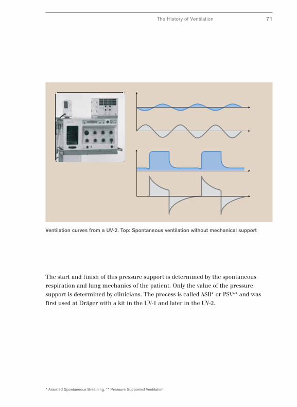
Ventilation curves from a UV-2. Top: Spontaneous ventilation without mechanical support
The History of Ventilation 71
The start and finish of this pressure support is determined by the spontaneous
respiration and lung mechanics of the patient. Only the value of the pressure
support is determined by clinicians. The process is called ASB* or PSV** and was
first used at Dräger with a kit in the UV-1 and later in the UV-2.
* Assisted Spontaneous Breathing, ** Pressure Supported Ventilation
Adaptation of Support to Spontaneous Respiration
Pressure-supported machine ventilation offers relief without forcing a mechanically
created ventilation pattern on the patient. Although machine ventilation adapts
itself to the spontaneous respiration of patients to a certain extent in pressure-
supported ventilation, there were some basic problems in the fine-tuning. Under
certain conditions the pressure-support curve does not match spontaneous
respiration. In addition, abrupt changes in pressure were unpleasant for the
patient. Hence improved synchronization of pressure-supported ventilation to the
patient’s respiration was required.
Adaptation of pressure-support to spontaneous respiration was initially achieved by a
manual correction to conventional pressure support. The manual adjustment of
machine pressure support to spontaneous respiration and lung mechanics first
became possible with the EV-A in 1982 using an additional adjustment parameter
which is generally called a “pressure ramp”. Since then the speed of the pressure
increase can be adapted to changing lung mechanics using this parameter.
Improved synchronization of pressure support with spontaneous respiration was
achieved.
The time response for support is not only dependent on the respiratory activity of
the patient but is also determined by mechanical factors such as resistance and
compliance. Therefore the length of pressure support can sometimes be shorter
than the respiratory effort of the patient. In this case the length of pressure support
can be extended by a longer interval of pressure increase. However, this manual
adjustment is often only successful in a limited number of cases.
72
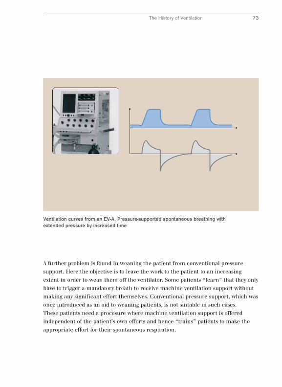
Ventilation curves from an EV-A. Pressure-supported spontaneous breathing withextended pressure by increased time
The History of Ventilation 73
A further problem is found in weaning the patient from conventional pressure
support. Here the objective is to leave the work to the patient to an increasing
extent in order to wean them off the ventilator. Some patients “learn” that they only
have to trigger a mandatory breath to receive machine ventilation support without
making any significant effort themselves. Conventional pressure support, which was
once introduced as an aid to weaning patients, is not suitable in such cases.
These patients need a procesure where machine ventilation support is offered
independent of the patient’s own efforts and hence “trains” patients to make the
appropriate effort for their spontaneous respiration.
Regulation of Pressure Support by the Patient
New ways had to be taken in the search for a method which provided pressure
support depending on spontaneous respiration. Until now all methods required
parameters to be set which determined the ventilation of the lungs. These
parameters were volume or pressure. Here we will simply describe them as
“ventilation parameters”. The result was that the command over time and volume
in machine ventilation lay with the operator and not with the patient, which was
particularly desired during the weaning process. This also applies to conventional
pressure support.
However, if absolute security of ventilation by setting ventilation parameters is done
away with and the emphasis is placed on supporting the patient in a targeted
manner with the problems of their insufficient spontaneous respiration, this opens
up completely new approaches. In this case the patient assumes responsibility for
ventilating their lungs and the operator simply ensures that the ventilator provides
sufficient support for spontaneous respiration of the patient by a suitable
inspiratory gas supply.
The problems of insufficient spontaneous respiration can be complex. If limited to
lung mechanics, there are two main problems. The respiratory apparatus can be
too rigid and the patient receives too little inspiratory gas. In this case we talk of a
restrictive dysfunction caused by too little compliance. On the other hand the
airway resistance can be too great. In this case there is an obstructive dysfunction
caused by too great resistance.
In order to target these dysfunctions, in the case of a restrictive dysfunction specific
measures would be taken to increase the volume with the smallest possible effort by
the patient, and in the case of an obstructive dysfunction the objective would be to
increase the flow in the same way. That is exactly the underlying principle for a
method which was launched in 1997 under the name of PAV* (24) and since 1997
has been known as PPS** and was available in a commercial available ventilator for
the first time with the Evita 4 and later with the Evita XL. In proportional pressure
support neither a defined volume nor a defined ventilation pressure is intended.
The goal is rather to adjust the percentage of respiratory work which man and
machine share.
74
* PAV =Proportional Assist Ventilation, ** PPS = Proportional Pressure Support
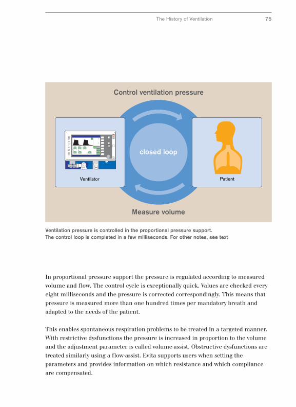
PatientVentilator
Control ventilation pressure
Measure volume
closed loop
Ventilation pressure is controlled in the proportional pressure support. The control loop is completed in a few milliseconds. For other notes, see text
The History of Ventilation 75
In proportional pressure support the pressure is regulated according to measured
volume and flow. The control cycle is exceptionally quick. Values are checked every
eight milliseconds and the pressure is corrected correspondingly. This means that
pressure is measured more than one hundred times per mandatory breath and
adapted to the needs of the patient.
This enables spontaneous respiration problems to be treated in a targeted manner.
With restrictive dysfunctions the pressure is increased in proportion to the volume
and the adjustment parameter is called volume-assist. Obstructive dysfunctions are
treated similarly using a flow-assist. Evita supports users when setting the
parameters and provides information on which resistance and which compliance
are compensated.
Issues with Ventilator Connection
76
Machine ventilation produces side effects such as the additional respiratory effort
caused by the resistance of the ventilation tube. The strain on the patient caused by
additional tube-related respiratory effort can be avoided by taking two steps. Either
the additional effort is compensated by the ventilator or the cause of the additional
effort is replaced with an alternative ventilation connection.
To understand compensation for tube-related respiratory effort it is useful to take a
closer look at the pressure conditions proximal and distal to the tube. If the patient
breathes through the tube, a drop in pressure occurs in the tube. The drop in
pressure increases as the patient draws the inspiratory gas in more vigorously
through the tube. The drop in pressure is dependent on the inspiratory gas flow.
Of course, the ventilator could supply greater ventilation pressure to compensate for
this drop in pressure and that is exactly the principle of ATC*, automatic tube
compensation. The ventilator exerts just enough pressure as the patient would have
to exert to transport the inspiratory gas through the tube. The patient experiences
this as a help. Although the patients are breathing through the tube, they do not
sense the resistance and the corresponding additional effort which is assumed by
the ventilator via the ATC– a phenomenon which is also called “electronic
extubation”. Automatic tube compensation was presented for the first time in 1997
with the launch of the Evita 4 and since then has gradually become standard in
intensive care ventilation.
An alternative ventilation connection is the respiratory mask which does not require
any significant additional effort in contrast to a tube. However, a ventilator has to be
adapted specially for ventilating via a mask since considerable leakage can occur
with masks. Adaptation is termed non-invasive ventilation NIV**. It consists of much
higher automatic leakage compensation and adjustment to ventilation monitoring
with selective alarm muting.
* ATC = Atomatic Tube Compensation, ** NIV = Non Invasive Ventilation
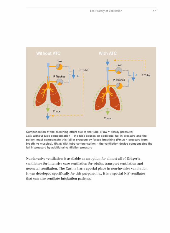
Without ATC With ATC
Paw
P TracheaP Trachea
P mus
P Tube
Paw
P mus
P Tube
Compensation of the breathing effort due to the tube. (Paw = airway pressure)Left: Without tube compensation – the tube causes an additional fall in pressure and thepatient must compensate this fall in pressure by forced breathing (Pmus = pressure frombreathing muscles). Right: With tube compensation – the ventilation device compensates thefall in pressure by additional ventilation pressure
Non-invasive ventilation is available as an option for almost all of Dräger’s
ventilators for intensive care ventilation for adults, transport ventilation and
neonatal ventilation. The Carina has a special place in non-invasive ventilation.
It was developed specifically for this purpose, i.e., it is a special NIV ventilator
that can also ventilate intubation patients.
The History of Ventilation 77
Specific Characteristics of Infant and
Neonatal Ventilation
Ventilation of infants and new born babies has a special status for two reasons.
Firstly, there are specific clinical problems when dealing with immature lungs and
secondly, there are additional technical challenges in neonatal ventilation.
Specific clinical problems of immature lungs includes, for example, the lack of
surfactant, a vital liquid film in the lung. A typical complication is aspiration of
amniotic fluid which frequently leads to pneumonia. Respiratory dysfunctions are
one of the main causes of neonatal deaths.
The technical challenges of neonatal ventilation lie in the type of ventilator
connection. The ventilation tube is normally not fixed in the windpipe but a so-
called uncuffed tube is used which is open to frequently unavoidably high leakage.
In addition, ventilators for newborn babies work with a continuous gas flow. In
principle this is an optimum solution for the small patients but creates additional
difficulties when monitoring ventilation. Additional demands on ventilators are
made when treating these clinical pictures described above where dramatic
changes in the lung mechanics can occur. The monitoring equipment must identify
these changes and ideally, the device should automatically adapt to the changes in
the lung mechanics.
In view of such challenges it is not surprising that a ventilator which satisfied all
the above criteria was not developed until the end of the1980s. The Babylog 8000
was the first neonatal ventilator which had integrated volume monitoring and
allowed the lung mechanics to be diagnosed. It offered flow measurement close to
the patient, combining automatic leakage compensation with a very sensitive
trigger for activating a machine breath by the weakest patient.
78
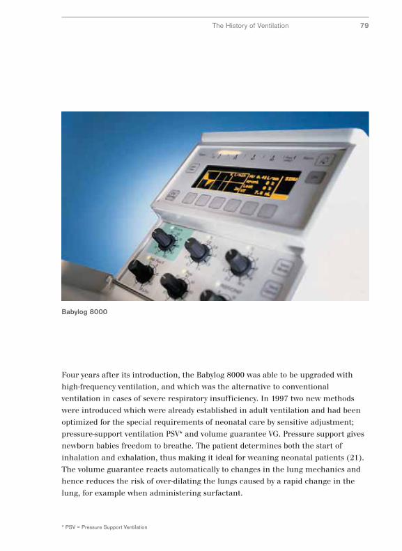
Babylog 8000
The History of Ventilation 79
Four years after its introduction, the Babylog 8000 was able to be upgraded with
high-frequency ventilation, and which was the alternative to conventional
ventilation in cases of severe respiratory insufficiency. In 1997 two new methods
were introduced which were already established in adult ventilation and had been
optimized for the special requirements of neonatal care by sensitive adjustment;
pressure-support ventilation PSV* and volume guarantee VG. Pressure support gives
newborn babies freedom to breathe. The patient determines both the start of
inhalation and exhalation, thus making it ideal for weaning neonatal patients (21).
The volume guarantee reacts automatically to changes in the lung mechanics and
hence reduces the risk of over-dilating the lungs caused by a rapid change in the
lung, for example when administering surfactant.
* PSV = Pressure Support Ventilation
SmartCare®
The ventilation processes described here may be very different but they all have one
thing in common: They are all adjusted manually according to the individual
decisions of clinicians. Such decisions do not happen often and frequently do not
follow a predetermined plan. Therefore guidelines, for example, the weaning
process, were drawn up to give exact instructions on actions such as setting
parameters.
In the middle of the 1990s it became common to implement guidelines on weaning
with the aid of a computer. The computer was in a position to use the ventilation
monitoring values to analyze the status of a patient and design a treatment plan
using the stored guidelines. Indeed, it went one step further and the computer was
authorized to implement steps in the treatment plan automatically and to control a
ventilator.
The first clinical tests of this new automatic weaning process were performed with
pressure-supported ventilation and were carried out with a modified computer-
controlled Evita 4. The results of the study were revolutionary and meant the
weaning process only took half as much time (19). The next step was the integration
of a computer for automatic weaning into a ventilator specially designed for this
purpose, the Evita XL and its market launch in 2005 under the product name
SmartCare®/PS. Computer-assisted automatic weaning had for the first time
become an integral part of a commercially available ventilator.
SmartCare/PS imitates clinicians during the weaning process. First a diagnosis of
spontaneous respiration is made on the basis of three parameters - respiration
frequency, tidal volume and end-tidal CO2. In cases of insufficient spontaneous
respiration pressure support is modified automatically to stabilize the patient and
spontaneous breathing. Once this has been achieve, pressure support is reduced
successively to a level where the patient can be expected to continue to breathe
without support. At this point SmartCare/PS carries out a maneuver, the
spontaneous respiration test. If this is successful, clinicians are informed of the
conclusion of the weaning process.
80
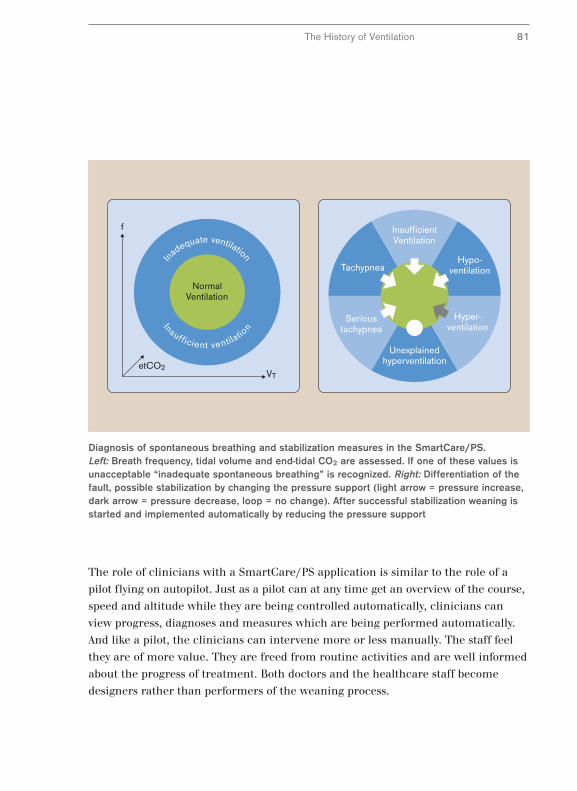
The History of Ventilation 81
The role of clinicians with a SmartCare/PS application is similar to the role of a
pilot flying on autopilot. Just as a pilot can at any time get an overview of the course,
speed and altitude while they are being controlled automatically, clinicians can
view progress, diagnoses and measures which are being performed automatically.
And like a pilot, the clinicians can intervene more or less manually. The staff feel
they are of more value. They are freed from routine activities and are well informed
about the progress of treatment. Both doctors and the healthcare staff become
designers rather than performers of the weaning process.
f
VTetCO2
In
adequate ventilation
Insufficient ventilatio
n
NormalVentilation
InsufficientVentilation
Unexplainedhyperventilation
Hyper-ventilation
Hypo-ventilation
Serioustachypnea
Tachypnea
Diagnosis of spontaneous breathing and stabilization measures in the SmartCare/PS.Left: Breath frequency, tidal volume and end-tidal CO2 are assessed. If one of these values isunacceptable “inadequate spontaneous breathing” is recognized. Right: Differentiation of thefault, possible stabilization by changing the pressure support (light arrow = pressure increase,dark arrow = pressure decrease, loop = no change). After successful stabilization weaning isstarted and implemented automatically by reducing the pressure support
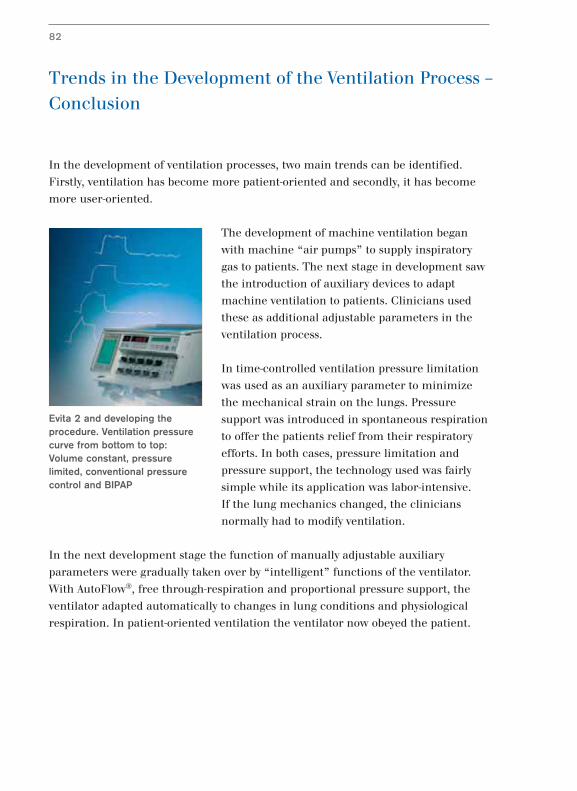
Trends in the Development of the Ventilation Process –
Conclusion
In the development of ventilation processes, two main trends can be identified.
Firstly, ventilation has become more patient-oriented and secondly, it has become
more user-oriented.
The development of machine ventilation began
with machine “air pumps” to supply inspiratory
gas to patients. The next stage in development saw
the introduction of auxiliary devices to adapt
machine ventilation to patients. Clinicians used
these as additional adjustable parameters in the
ventilation process.
In time-controlled ventilation pressure limitation
was used as an auxiliary parameter to minimize
the mechanical strain on the lungs. Pressure
support was introduced in spontaneous respiration
to offer the patients relief from their respiratory
efforts. In both cases, pressure limitation and
pressure support, the technology used was fairly
simple while its application was labor-intensive.
If the lung mechanics changed, the clinicians
normally had to modify ventilation.
In the next development stage the function of manually adjustable auxiliary
parameters were gradually taken over by “intelligent” functions of the ventilator.
With AutoFlow®, free through-respiration and proportional pressure support, the
ventilator adapted automatically to changes in lung conditions and physiological
respiration. In patient-oriented ventilation the ventilator now obeyed the patient.
82
Evita 2 and developing theprocedure. Ventilation pressurecurve from bottom to top:Volume constant, pressurelimited, conventional pressurecontrol and BIPAP
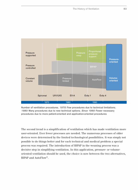
1970 1980 1990
Evita 4Evita 1EV-AUV1/UV2Spiromat
Volume-oriented
Pressure-oriented
Constantvolume
Pressurelimited
Pressuresupported
Pressurecontrolled
Pressureramp
Proportionalpressuresupport
BIPAP
AutoFlow
Number of ventilation procedures. 1970: Few procedures due to technical limitations. 1980: Many procedures due to new technical options. Since 1990: Fewer necessaryprocedures due to more patient-oriented and application-oriented procedures
The History of Ventilation 83
The second trend is a simplification of ventilation which has made ventilation more
user-oriented. Ever fewer processes are needed. The numerous processes of older
devices were determined by the limited technological possibilities. It was simply not
possible to do things better and for each technical and medical problem a special
process was required. The introduction of BIPAP in the weaning process was a
decisive step in simplifying ventilation. In this application, pressure- or volume-
oriented ventilation should be used, the choice is now between the two alternatives,
BIPAP and AutoFlow®.
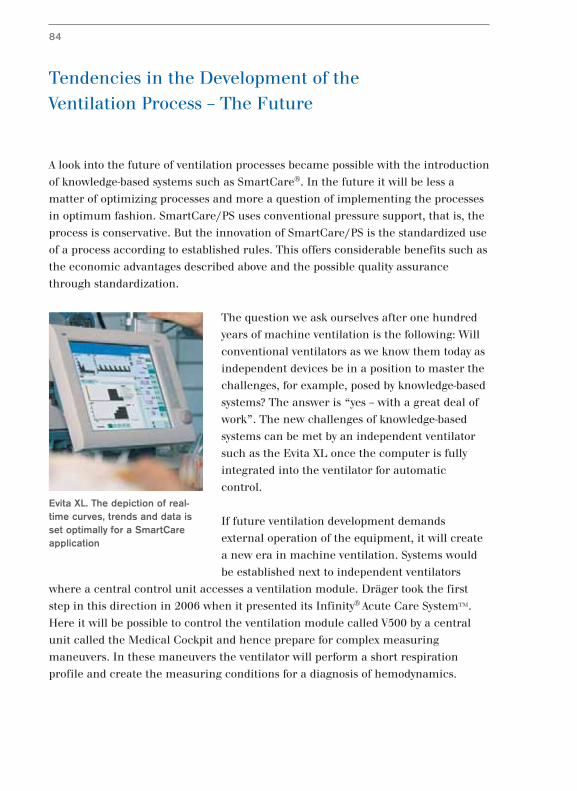
Tendencies in the Development of the
Ventilation Process – The Future
A look into the future of ventilation processes became possible with the introduction
of knowledge-based systems such as SmartCare®. In the future it will be less a
matter of optimizing processes and more a question of implementing the processes
in optimum fashion. SmartCare/PS uses conventional pressure support, that is, the
process is conservative. But the innovation of SmartCare/PS is the standardized use
of a process according to established rules. This offers considerable benefits such as
the economic advantages described above and the possible quality assurance
through standardization.
The question we ask ourselves after one hundred
years of machine ventilation is the following: Will
conventional ventilators as we know them today as
independent devices be in a position to master the
challenges, for example, posed by knowledge-based
systems? The answer is “yes – with a great deal of
work”. The new challenges of knowledge-based
systems can be met by an independent ventilator
such as the Evita XL once the computer is fully
integrated into the ventilator for automatic
control.
If future ventilation development demands
external operation of the equipment, it will create
a new era in machine ventilation. Systems would
be established next to independent ventilators
where a central control unit accesses a ventilation module. Dräger took the first
step in this direction in 2006 when it presented its Infinity® Acute Care System™.
Here it will be possible to control the ventilation module called V500 by a central
unit called the Medical Cockpit and hence prepare for complex measuring
maneuvers. In these maneuvers the ventilator will perform a short respiration
profile and create the measuring conditions for a diagnosis of hemodynamics.
84
Evita XL. The depiction of real-time curves, trends and data isset optimally for a SmartCareapplication
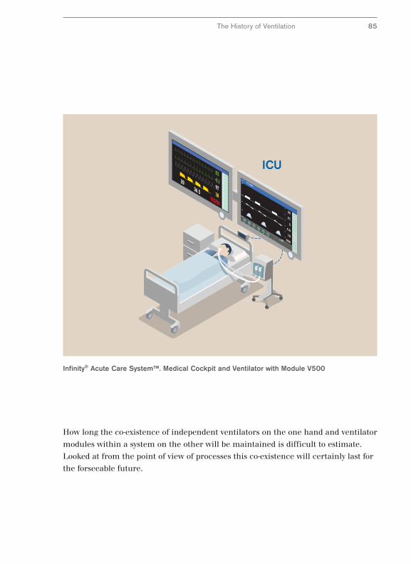
Infinity® Acute Care System™. Medical Cockpit and Ventilator with Module V500
How long the co-existence of independent ventilators on the one hand and ventilator
modules within a system on the other will be maintained is difficult to estimate.
Looked at from the point of view of processes this co-existence will certainly last for
the forseeable future.
The History of Ventilation 85
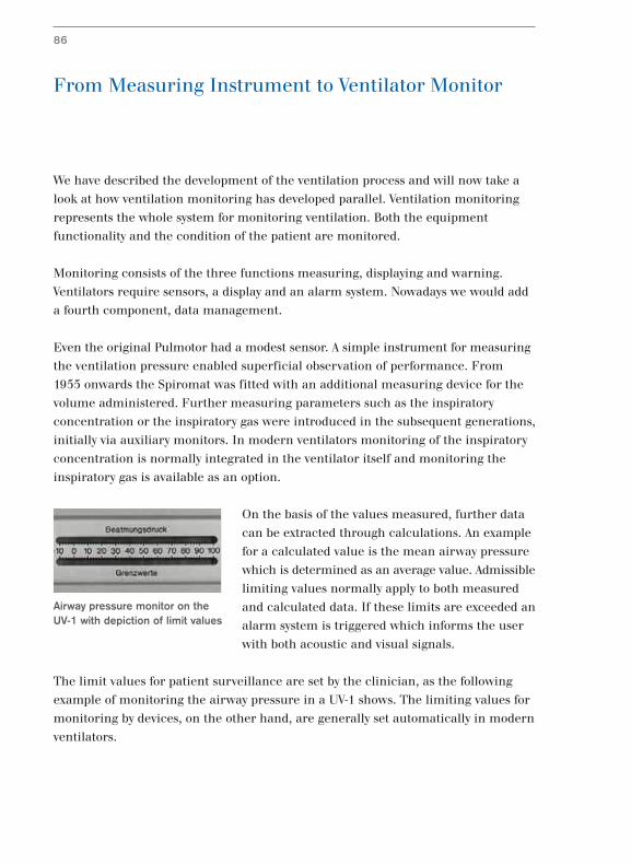
From Measuring Instrument to Ventilator Monitor
We have described the development of the ventilation process and will now take a
look at how ventilation monitoring has developed parallel. Ventilation monitoring
represents the whole system for monitoring ventilation. Both the equipment
functionality and the condition of the patient are monitored.
Monitoring consists of the three functions measuring, displaying and warning.
Ventilators require sensors, a display and an alarm system. Nowadays we would add
a fourth component, data management.
Even the original Pulmotor had a modest sensor. A simple instrument for measuring
the ventilation pressure enabled superficial observation of performance. From
1955 onwards the Spiromat was fitted with an additional measuring device for the
volume administered. Further measuring parameters such as the inspiratory
concentration or the inspiratory gas were introduced in the subsequent generations,
initially via auxiliary monitors. In modern ventilators monitoring of the inspiratory
concentration is normally integrated in the ventilator itself and monitoring the
inspiratory gas is available as an option.
On the basis of the values measured, further data
can be extracted through calculations. An example
for a calculated value is the mean airway pressure
which is determined as an average value. Admissible
limiting values normally apply to both measured
and calculated data. If these limits are exceeded an
alarm system is triggered which informs the user
with both acoustic and visual signals.
The limit values for patient surveillance are set by the clinician, as the following
example of monitoring the airway pressure in a UV-1 shows. The limiting values for
monitoring by devices, on the other hand, are generally set automatically in modern
ventilators.
86
Airway pressure monitor on theUV-1 with depiction of limit values
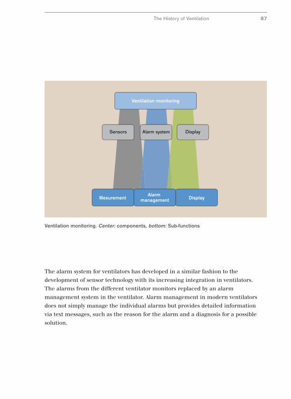
Sensors Alarm system Display
Ventilation monitoring
DisplayMesurementAlarm
management
Ventilation monitoring. Center: components, bottom: Sub-functions
The History of Ventilation 87
The alarm system for ventilators has developed in a similar fashion to the
development of sensor technology with its increasing integration in ventilators.
The alarms from the different ventilator monitors replaced by an alarm
management system in the ventilator. Alarm management in modern ventilators
does not simply manage the individual alarms but provides detailed information
via text messages, such as the reason for the alarm and a diagnosis for a possible
solution.
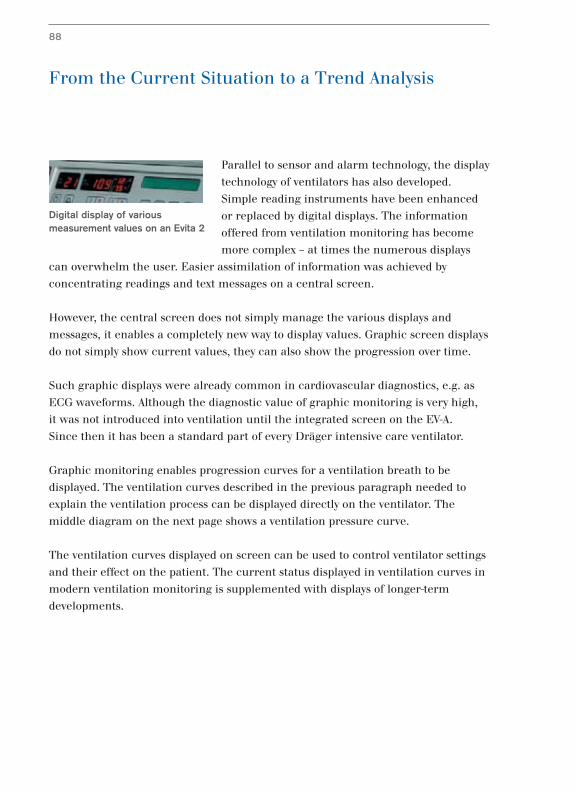
From the Current Situation to a Trend Analysis
Parallel to sensor and alarm technology, the display
technology of ventilators has also developed.
Simple reading instruments have been enhanced
or replaced by digital displays. The information
offered from ventilation monitoring has become
more complex – at times the numerous displays
can overwhelm the user. Easier assimilation of information was achieved by
concentrating readings and text messages on a central screen.
However, the central screen does not simply manage the various displays and
messages, it enables a completely new way to display values. Graphic screen displays
do not simply show current values, they can also show the progression over time.
Such graphic displays were already common in cardiovascular diagnostics, e.g. as
ECG waveforms. Although the diagnostic value of graphic monitoring is very high,
it was not introduced into ventilation until the integrated screen on the EV-A.
Since then it has been a standard part of every Dräger intensive care ventilator.
Graphic monitoring enables progression curves for a ventilation breath to be
displayed. The ventilation curves described in the previous paragraph needed to
explain the ventilation process can be displayed directly on the ventilator. The
middle diagram on the next page shows a ventilation pressure curve.
The ventilation curves displayed on screen can be used to control ventilator settings
and their effect on the patient. The current status displayed in ventilation curves in
modern ventilation monitoring is supplemented with displays of longer-term
developments.
88
Digital display of variousmeasurement values on an Evita 2
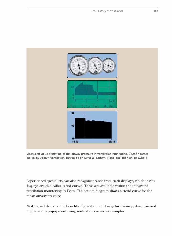
Measured value depiction of the airway pressure in ventilation monitoring. Top: Spiromatindicator, center: Ventilation curves on an Evita 2, bottom: Trend depiction on an Evita 4
The History of Ventilation 89
Experienced specialists can also recognize trends from such displays, which is why
displays are also called trend curves. These are available within the integrated
ventilation monitoring in Evita. The bottom diagram shows a trend curve for the
mean airway pressure.
Next we will describe the benefits of graphic monitoring for training, diagnosis and
implementing equipment using ventilation curves as examples.
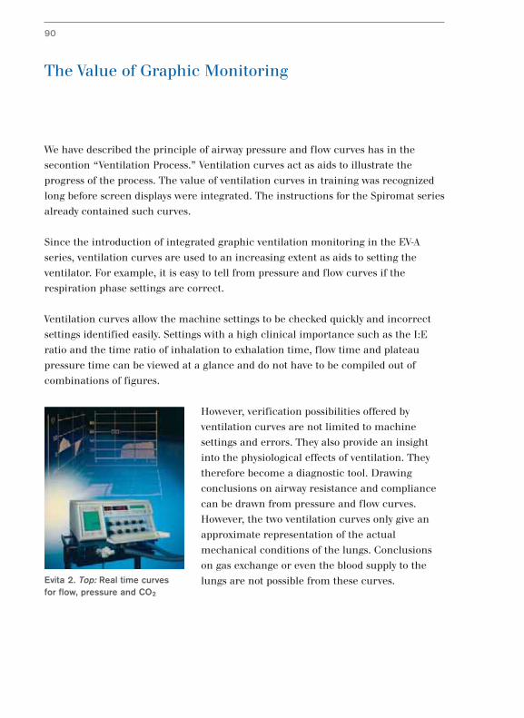
The Value of Graphic Monitoring
We have described the principle of airway pressure and flow curves has in the
secontion “Ventilation Process.” Ventilation curves act as aids to illustrate the
progress of the process. The value of ventilation curves in training was recognized
long before screen displays were integrated. The instructions for the Spiromat series
already contained such curves.
Since the introduction of integrated graphic ventilation monitoring in the EV-A
series, ventilation curves are used to an increasing extent as aids to setting the
ventilator. For example, it is easy to tell from pressure and flow curves if the
respiration phase settings are correct.
Ventilation curves allow the machine settings to be checked quickly and incorrect
settings identified easily. Settings with a high clinical importance such as the I:E
ratio and the time ratio of inhalation to exhalation time, flow time and plateau
pressure time can be viewed at a glance and do not have to be compiled out of
combinations of figures.
However, verification possibilities offered by
ventilation curves are not limited to machine
settings and errors. They also provide an insight
into the physiological effects of ventilation. They
therefore become a diagnostic tool. Drawing
conclusions on airway resistance and compliance
can be drawn from pressure and flow curves.
However, the two ventilation curves only give an
approximate representation of the actual
mechanical conditions of the lungs. Conclusions
on gas exchange or even the blood supply to the
lungs are not possible from these curves.
90
Evita 2. Top: Real time curves for flow, pressure and CO2
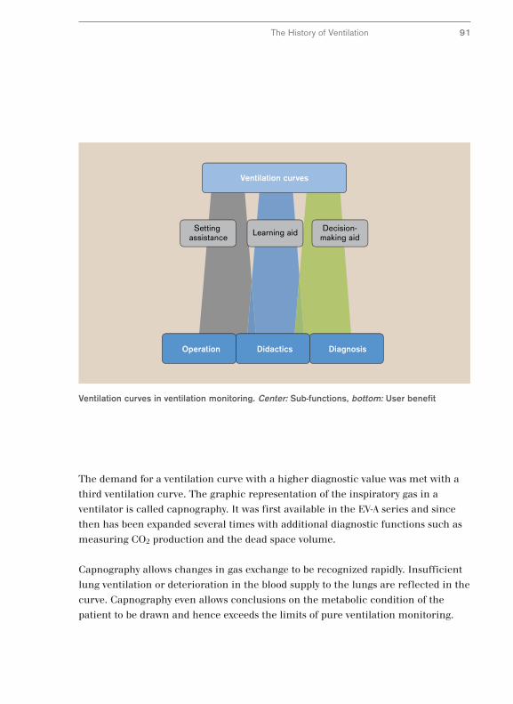
Learning aid Decision-making aid
Setting assistance
Ventilation curves
DiagnosisOperation Didactics
Ventilation curves in ventilation monitoring. Center: Sub-functions, bottom: User benefit
The History of Ventilation 91
The demand for a ventilation curve with a higher diagnostic value was met with a
third ventilation curve. The graphic representation of the inspiratory gas in a
ventilator is called capnography. It was first available in the EV-A series and since
then has been expanded several times with additional diagnostic functions such as
measuring CO2 production and the dead space volume.
Capnography allows changes in gas exchange to be recognized rapidly. Insufficient
lung ventilation or deterioration in the blood supply to the lungs are reflected in the
curve. Capnography even allows conclusions on the metabolic condition of the
patient to be drawn and hence exceeds the limits of pure ventilation monitoring.
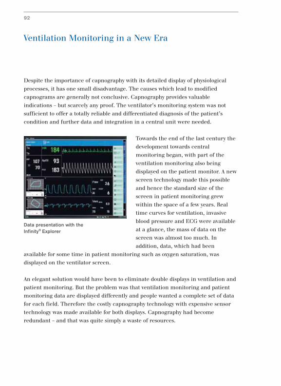
Ventilation Monitoring in a New Era
Despite the importance of capnography with its detailed display of physiological
processes, it has one small disadvantage. The causes which lead to modified
capnograms are generally not conclusive. Capnography provides valuable
indications – but scarcely any proof. The ventilator's monitoring system was not
sufficient to offer a totally reliable and differentiated diagnosis of the patient’s
condition and further data and integration in a central unit were needed.
Towards the end of the last century the
development towards central
monitoring began, with part of the
ventilation monitoring also being
displayed on the patient monitor. A new
screen technology made this possible
and hence the standard size of the
screen in patient monitoring grew
within the space of a few years. Real
time curves for ventilation, invasive
blood pressure and ECG were available
at a glance, the mass of data on the
screen was almost too much. In
addition, data, which had been
available for some time in patient monitoring such as oxygen saturation, was
displayed on the ventilator screen.
An elegant solution would have been to eliminate double displays in ventilation and
patient monitoring. But the problem was that ventilation monitoring and patient
monitoring data are displayed differently and people wanted a complete set of data
for each field. Therefore the costly capnography technology with expensive sensor
technology was made available for both displays. Capnography had become
redundant – and that was quite simply a waste of resources.
92
Data presentation with the Infinity® Explorer
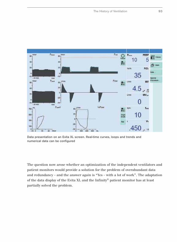
Data presentation on an Evita XL screen. Real-time curves, loops and trends andnumerical data can be configured
The History of Ventilation 93
The question now arose whether an optimization of the independent ventilators and
patient monitors would provide a solution for the problem of overabundant data
and redundancy – and the answer again is “Yes – with a lot of work”. The adaptation
of the data display of the Evita XL and the Infinity® patient monitor has at least
partially solved the problem.
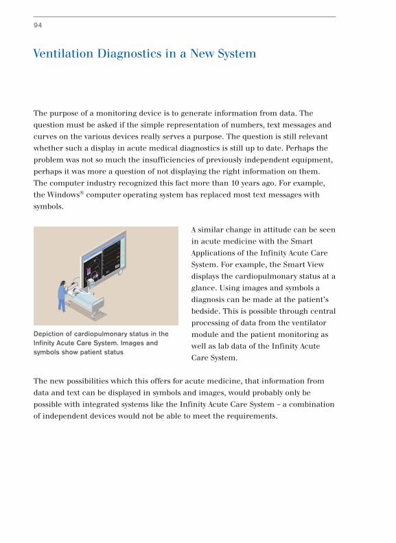
Ventilation Diagnostics in a New System
The purpose of a monitoring device is to generate information from data. The
question must be asked if the simple representation of numbers, text messages and
curves on the various devices really serves a purpose. The question is still relevant
whether such a display in acute medical diagnostics is still up to date. Perhaps the
problem was not so much the insufficiencies of previously independent equipment,
perhaps it was more a question of not displaying the right information on them.
The computer industry recognized this fact more than 10 years ago. For example,
the Windows® computer operating system has replaced most text messages with
symbols.
A similar change in attitude can be seen
in acute medicine with the Smart
Applications of the Infinity Acute Care
System. For example, the Smart View
displays the cardiopulmonary status at a
glance. Using images and symbols a
diagnosis can be made at the patient’s
bedside. This is possible through central
processing of data from the ventilator
module and the patient monitoring as
well as lab data of the Infinity Acute
Care System.
The new possibilities which this offers for acute medicine, that information from
data and text can be displayed in symbols and images, would probably only be
possible with integrated systems like the Infinity Acute Care System – a combination
of independent devices would not be able to meet the requirements.
94
Depiction of cardiopulmonary status in theInfinity Acute Care System. Images andsymbols show patient status
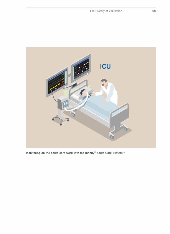
Monitoring on the acute care ward with the Infinity® Acute Care System™
The History of Ventilation 95
Performance and Operation
96
After the ventilation process and monitoring, we now come to to the operating
concept for ventilation and monitoring from a historical point of view. In contrast to
the ventilation process and ventilation monitoring, the operating concept for
ventilators was developed very late. The operating elements were initially placed
randomly and were unsuited to the user.
The first ventilators were easy to operate because of their limited performance.
However, with enhanced performance the number of operating elements grew. The
curve shows the number of operating elements and the performance for various
devices.
The diagram contains the following simplifications: The scope of performance of a
ventilator consists of the sum of ventilation processes and other functions. The
number of operating elements only includes dials. According to this schema the
Spiromat had only one ventilation process and with sigh ventilation just one other
function. The machine could be relatively easily operated with six dials. The UV-2
had three ventilation processes and three additional functions: in addition to sigh
ventilation, adjustable O2 concentration and pressure limitation were added.
Operating the machine was now quite complicated with eleven dials.
In the following machine generations ways were found to simplify operating the
machines. For example, dials on the EV-A had two functions to stop the number of
dials growing even further. However, these simplifications frequently proved to be
simply cosmetic. Operating the machine appeared simple but its operation became
more complicated.
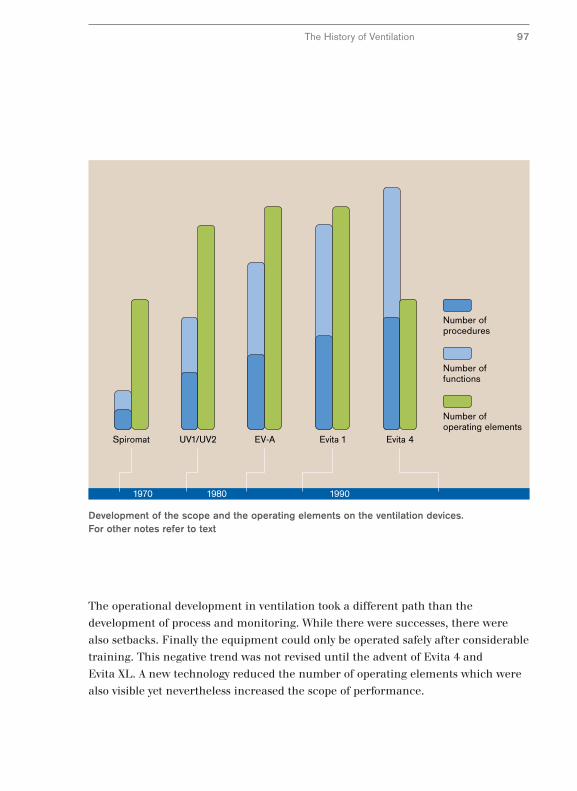
1970 1980 1990
Evita 4Evita 1EV-AUV1/UV2Spiromat
Number of procedures
Number of functions
Number of operating elements
Development of the scope and the operating elements on the ventilation devices.For other notes refer to text
The History of Ventilation 97
The operational development in ventilation took a different path than the
development of process and monitoring. While there were successes, there were
also setbacks. Finally the equipment could only be operated safely after considerable
training. This negative trend was not revised until the advent of Evita 4 and
Evita XL. A new technology reduced the number of operating elements which were
also visible yet nevertheless increased the scope of performance.
High Performance, Easy to Use – A Contradiction?
Of course there were remarkable advances in the development of the operating
concept and not just the setbacks described above, such as the introduction of the
central screen as a control instrument for settings.
Another advance was the introduction of a user guide with protection devices for
potentially dangerous settings. As early as 1982 the EV-A series automatically
recognized excessive ventilation pressure or an unusual respiration time ratio.
LEDs on the corresponding operating elements and screen alerts not only warned
personnel about dangers but also suggested countermeasures.
This meant that the operating process was partially guided and users achieved their
goal, so to speak, in dialogue with the machine. For example, the device would
warn the user of potentially dangerous settings for the respiration time ratio. The
support which a device offers for setting parameters is called the user interface.
A device with a good user interface is basically self-explanatory. The operating
concept for such devices, which is comprehensible in itself once a few basic
elements have been learned, is called intuitive. An intuitive user interface was first
introduced in 1995 with the Evita 4 using the new technology and enhanced in the
Evita XL in 2002. The control elements are accessible via a screen except for a few
frequently used functions. This touch screen technology offered two advantages.
The first advantage is the directed operation since only control elements which can
actually be operated at the current moment are displayed, thereby reducing the
number. An example of this is setting the ventilation parameters in two different
ventilation processes. While one process requires nine parameters, the other only
requires four. If no settings are being introduced, all control elements are faded out
and the screen becomes a pure ventilation monitor.
98
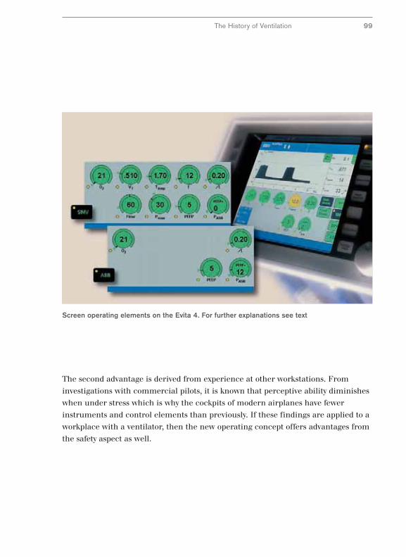
Screen operating elements on the Evita 4. For further explanations see text
The History of Ventilation 99
The second advantage is derived from experience at other workstations. From
investigations with commercial pilots, it is known that perceptive ability diminishes
when under stress which is why the cockpits of modern airplanes have fewer
instruments and control elements than previously. If these findings are applied to a
workplace with a ventilator, then the new operating concept offers advantages from
the safety aspect as well.
Standardized Operation – A Vision?
Apart from the need to simplify operating a ventilator there is the requirement to
simplify operating equipment within acute medicine. A simplification of operating
concepts began at Dräger at the beginning of the 1990s with the introduction of a
central dial in connection with a menu-guided interface.
This standard operating concept was gradually implemented across all areas of
acute care. In anesthesiology, the anesthetic device Cicero was introduced in 1995
to intensive care ventilation with the Evita 4. Its first appearance in the heat therapy
area waswith the incubator Caleo and finally it came to emergency medicine in
2003 with the Oxylog® 3000. Over time the operating concepts resembled each
other increasingly and with the introduction in 2003 of the anesthetic device Zeus
and the Evita XL Dräger could offer a largely harmonized operating concept with a
number of homologous operating elements in the OP area and in intensive care.
In spite of extensive harmonizing of operating concepts each device had a stand-
alone operation causing two problems. Firstly, the problem described in diagnostics
of redundancy applies also to operating units in the acute care workplaces. If in
intensive care there are three modalities ventilation, infusion therapy and
monitoring, then three devices are not necessarily needed to operate them – two
would be simpler and more sensible. Progress would be operating all modalities
with only one or two universal operating units with the same architecture and the
same hardware.
A system which could solve these problems would need unit to integrate modules to
a degree unknown to date. Not only would data transfer from the module to the
central unit have to be guaranteed, also data transfer to activate the modules from
the central unit must be possible. Dräger’s first experience with such bidirectional
data transfer was with the Evita 4 since 1995. Here, however, this was limited to the
ventilator with its separate operating unit.
100
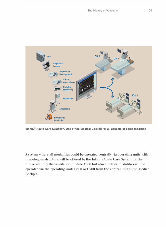
7993167/69118
The History of Ventilation 101
A system where all modalities could be operated centrally via operating units with
homologous structure will be offered by the Infinity Acute Care System. In the
future not only the ventilation module V500 but also all other modalities will be
operated via the operating units C500 or C700 from the central unit of the Medical
Cockpit.
Infinity® Acute Care System™. Use of the Medical Cockpit for all aspects of acute medicine
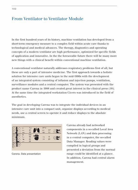
From Ventilator to Ventilator Module
In the first hundred years of its history, machine ventilation has developed from a
short-term emergency measure to a complex field within acute care thanks to
technological and medical advances. The therapy, diagnostics and operating
concepts of a modern ventilator are high performance, optimized for specific fields
of application and innovative. In the the foreseeable future there will be many more
new things with a clinical benefit within conventional machine ventilation.
A conventional ventilator naturally addresses respiratory problems first of all, but
these are only a part of intensive medicine. The first approach towards a holistic
solution for intensive care units began in the mid-1980s with the development
of an integrated system consisting of infusion and injection pumps, ventilation,
surveillance modules and a central computer. The system was presented with the
product name Carena in 1988 and created great interest in the clinical press (18).
At the same time the integrated workstation Cicero was introduced in the field of
anesthetics.
The goal in developing Carena was to integrate the individual devices in an
intensive care unit into a compact unit, organize displays according to medical
needs, use a central screen to operate it and reduce displays to the absolute
minimum.
Carena already had networked
components in a so-called Local Area
Network (LAN) and data processing
in a central computer, the so-called
Data Manager. Reading values were
compiled in logical groups and
presented a deviation from the normal
range could be identified at a glance.
In addition, Carena had central alarm
management.
102
Carena. Data presentation
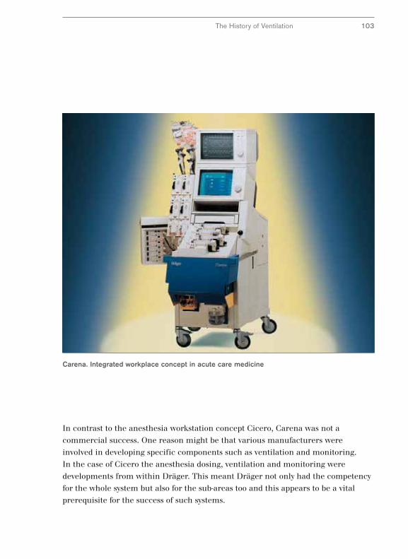
Carena. Integrated workplace concept in acute care medicine
The History of Ventilation 103
In contrast to the anesthesia workstation concept Cicero, Carena was not a
commercial success. One reason might be that various manufacturers were
involved in developing specific components such as ventilation and monitoring.
In the case of Cicero the anesthesia dosing, ventilation and monitoring were
developments from within Dräger. This meant Dräger not only had the competency
for the whole system but also for the sub-areas too and this appears to be a vital
prerequisite for the success of such systems.
From Module to Acute Care System
Both Carena and Cicero were closed workstations. However, the individual
workstations were not isolated, rather they were part of a whole, namely acute care.
Within the sub-areas of acute care the same or similar processes such as monitoring
and ventilation are performed and often the same people perform them.
Acute care accompanies a process chain which can be easily demonstrated by
following the path of a patient throughout their treatment. In a simplified example
this begins with emergency care and the patient being admitted into hospital.
A general diagnosis could be followed by surgery, with the process chain passing
through the operating theater and the recovery room. This is followed by treatment
in the intensive care ward or high-dependency unit before the patient is discharged
after further treatment in a low-care unit.
If this process chain passes through the different sections with rigid divisions then
the problems we have described that Carena and Cicero were meant to resolve will
remain isolated in the workstations and not cross the boundaries. The problems are
lack of standardization and gaps or unmanageable information. In addition there
may be bottlenecks and waiting times when passing through the various stations.
The different stations may have organized their workstations differently and if they
are located far apart this adds the specific problems of patient transport.
This begs the question which we already asked about the future of conventional
ventilators: Can conventional apparatus and workstation concepts be optimized
within the whole acute care field with standardized operability and standardized
presentation of information so that they can be arranged ergonomically and
minimize the dangers of patient transport? And the answer is, again, the same:
“Yes – with a lot of work”.
104
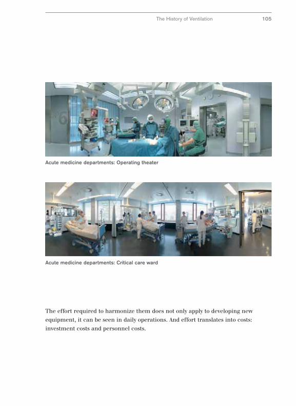
Acute medicine departments: Critical care ward
Acute medicine departments: Operating theater
The effort required to harmonize them does not only apply to developing new
equipment, it can be seen in daily operations. And effort translates into costs:
investment costs and personnel costs.
The History of Ventilation 105
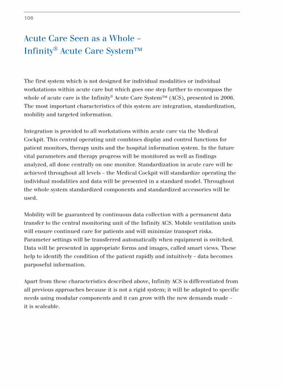
Acute Care Seen as a Whole –
Infinity® Acute Care System™
The first system which is not designed for individual modalities or individual
workstations within acute care but which goes one step further to encompass the
whole of acute care is the Infinity® Acute Care System™ (ACS), presented in 2006.
The most important characteristics of this system are integration, standardization,
mobility and targeted information.
Integration is provided to all workstations within acute care via the Medical
Cockpit. This central operating unit combines display and control functions for
patient monitors, therapy units and the hospital information system. In the future
vital parameters and therapy progress will be monitored as well as findings
analyzed, all done centrally on one monitor. Standardization in acute care will be
achieved throughout all levels – the Medical Cockpit will standardize operating the
individual modalities and data will be presented in a standard model. Throughout
the whole system standardized components and standardized accessories will be
used.
Mobility will be guaranteed by continuous data collection with a permanent data
transfer to the central monitoring unit of the Infinity ACS. Mobile ventilation units
will ensure continued care for patients and will minimize transport risks.
Parameter settings will be transferred automatically when equipment is switched.
Data will be presented in appropriate forms and images, called smart views. These
help to identify the condition of the patient rapidly and intuitively – data becomes
purposeful information.
Apart from these characteristics described above, Infinity ACS is differentiated from
all previous approaches because it is not a rigid system; it will be adapted to specific
needs using modular components and it can grow with the new demands made –
it is scaleable.
106
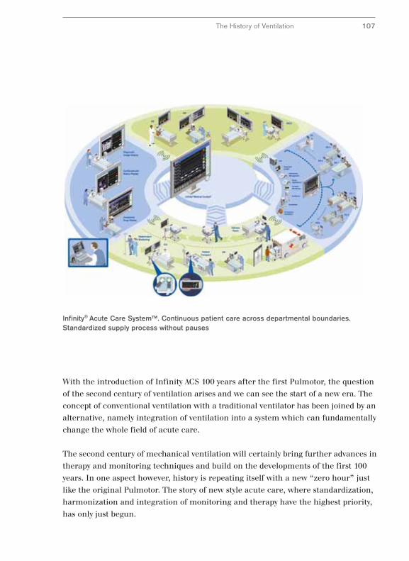
Infinity® Acute Care System™. Continuous patient care across departmental boundaries.Standardized supply process without pauses
The History of Ventilation 107
With the introduction of Infinity ACS 100 years after the first Pulmotor, the question
of the second century of ventilation arises and we can see the start of a new era. The
concept of conventional ventilation with a traditional ventilator has been joined by an
alternative, namely integration of ventilation into a system which can fundamentally
change the whole field of acute care.
The second century of mechanical ventilation will certainly bring further advances in
therapy and monitoring techniques and build on the developments of the first 100
years. In one aspect however, history is repeating itself with a new “zero hour” just
like the original Pulmotor. The story of new style acute care, where standardization,
harmonization and integration of monitoring and therapy have the highest priority,
has only just begun.
108
Bibliography
1 Bahns E. (1995) BIPAP – Zwei Schritte nach vorn in der Intensivbeatmung.
Dräger, Lübeck.
2 Baum M., Benzer H. (1993) Einsatz von Atemhilfen.
In: Benzer H., Burchardi H., Larsen R., Suter P.M. (Hrsg.),
Lehrbuch der Anaesthesiologie und Intensivmedizin. 405 – 437.
3 Baum M., Benzer H., Putensen Ch., Koller W., Putz G.(1989)
Biphasic Positive Airway Pressure (BIPAP) – eine neue Form der
augmentierenden Beatmung. Anaesthesist 38: 452 – 458.
4 Burchardi H. (1993), Pathophysiologie der respiratorischen Störungen.
In: Benzer H., Burchardi H., Larsen R., Suter P.M. (Hrsg.),
Lehrbuch der Anaesthesiologie und Intensivmedizin. 335 – 349.
5 Colice G.L. (1994) Historical perspective on the development of mechanical
ventilation. In: Tobin M.J. (Hrsg.), Principles and practice of mechanical
ventilation. 1 – 35.
6 Dönhardt A. (1984) Beatmung mit der Eisernen Lunge.
In: Lawin P., Peter K., Scherer R. (Hrsg.), Maschinelle Beatmung
gestern – heute – morgen. 20 – 27.
7 Dräger H. (1917) Das Werden des Pulmotors,
Drägerhefte Nr. 57/58. 495 – 496.
8 Dräger H. Lebenserinnerungen von Heinrich Dräger , Alfred Jansen,
Hamburg (Erstdruck 1914).
9 Freytag K. (1970) Dräger Beatmungsgeräte. Drägerhefte Nr. 281 13 – 26.
10 Fürniß H. (1984) Vom Dräger Poliomaten zum Spiromaten.
In: Lawin P., Peter K., Scherer R. (Hrsg.), Maschinelle Beatmung
gestern – heute – morgen. 28 – 43.
11 Fürniß H. Hollmann F. (1955) Der Pulmotor in neuer Form,
Drägerhefte Nr. 227.4867 – 4872.
12 Haase-Lampe W. (1923) Die Pulmotor-Frage im Reichsgesundheitswesen
Drägerhefte Nr. 91.919 – 921.
109
13 Haase-Lampe W. (1924) Der Pulmotorstreit, Drägerhefte Nr. 99.1019 – 1022.
14 Haase-Lampe W. (1929) Pulmotor-Streit. Pulmotor-Nachrichten Nr. 1,
Beilage der Drägerhefte.
15 Haase-Lampe W. (1930) Merkenswerte Wiederbelebungserfolge.
Pulmotor-Nachrichten Nr. 4, Beilage der Drägerhefte.
16 Haase-Lampe W., Thiel K. (1946) Pulmotor – Sauerstoff-
Wiederbelebungsmaschine für künstliche Beatmung, Antäus, Lübeck.
17 Hörmann Ch., Baum M., Putensen Ch., Mutz N. J., Benzer H. (1994)
Biphasic Positive Airway Pressure (BIPAP) – ein neuer augmentierender
Beatmungsmode. European Journal of Anaesthesiology 11: 37 – 42.
18 Lawin, P. Opderbecke H.W. (1994) Organisation der Intensivmedizin.
In: Lawin, P. (Hrsg.) Praxis der Intensivbehandlung S. 15 – 63.
19 Lellouche F, Mancebo J, Jolliet P, Roeseler J, Schortgen F, Dojat M, Cabello B,
Bouadma L, Rodriguez P, Maggiore S, Reynaert M, Mersmann S and
Brochard L. (2006) Am J Respir Crit Care Med 174: 894–900.
20 Putensen C, Mutz NJ, Putensen-Himmer G, Zinserling J (1999)
Spontaneous breathing during ventilatory support improves ventilation-
perfusion distributions in patients with acute respiratory distress syndrome.
Am J Respir Crit Care Med, 159: 1241–1248.
21 Rozé J.C. Krüger T. (1997) Pressure Support Ventilation – eine neue
getriggerte Beatmungsform für Neonaten. Dräger, Lübeck.
22 Schröder H. (1913) Die Pulmotor-Organisation. Drägerhefte Nr. 15.140.
23 Schröder H. (1914) Dräger-Baby-Pulmotor. Drägerhefte Nr. 19.172.
24 Younes M. (1994) Proportional assist ventilation (PAV).
In: Tobin M.J. (Hrsg.), Principles and practice of mechanical ventilation.
349 - 369.

110
Dr. Ernst Bahns, born in 1951, is a physiologist and has worked for Dräger for twenty years. He currentlyworks in the Medical Division’s marketing department. His work includes customer and employee training.He has already written several articles on clinicalapplications and the history of ventilation.
The Author

111


90
97
43
4 /
09
.07
-1 /
gm
-dw
/ P
rinte
d in
Ger
man
y /
Chl
orin
e-fr
ee -
envi
ronm
enta
lly c
ompa
tible
/ S
ubje
ct to
mod
ifica
tions
/ ©
20
07 D
räge
r M
edic
al A
G &
Co.
KG
Europe, Middle East, Africa, Latin America,Asia, Pacific:
Dräger Medical AG & Co. KG Moislinger Allee 53–5523542 LübeckGERMANYTel: +49-451-882-0Fax: +49-451-882-2080E-mail: [email protected]
www.draeger.com