istand – i can stand - machine intelligence lab - university of florida
TRANSCRIPT
EEL 5666: IMDL Robot Design Report iSTAND
Subrat Nayak, ECE Dept, U of F Page 1 of 76
iSTAND – I can Stand
A Self Balancing Platform
to demonstrate the concept of Inverted Pendulum
SUBRAT NAYAK
UFID: 5095-9761
For
EEL 5666 - Intelligent Machines Design Laboratory (Spring 2008)
Department of Electrical and Computer Engineering
University of Florida
Instructors
Dr. A. Antonio Arroyo
Dr. Eric M. Schwartz
Teaching Asst
Mike Pridgen
Adam Barnett
Sara Keen
EEL 5666: IMDL Robot Design Report iSTAND
Subrat Nayak, ECE Dept, U of F Page 2 of 76
Table of Content
1.0 Abstract__________________________________________________________________ 3
2.0 Executive Summary ________________________________________________________ 4
3.0 Introduction ______________________________________________________________ 5
4.0 Integrated System__________________________________________________________ 6
4.1.0 The MAVRIC IIB board_______________________________________________________ 6
4.2.0 AVR USB JTAG Debugger & ISP Programmer ___________________________________ 8
5.0 Mobile Platform __________________________________________________________ 11
6.0 Actuation _______________________________________________________________ 14
6.1.1 MOTOR 1 – ________________________________________________________________ 14
6.1.2 MOTOR 2 – ________________________________________________________________ 17
6.2.1 Wheels – ___________________________________________________________________ 17
6.3.1 Hub –______________________________________________________________________ 17
7.0 Sensors _________________________________________________________________ 18
7.1 Tilt Angle – ACCELEROMETER____________________________________________ 19
7.1.1 Principle of Operation________________________________________________________ 20
7.1.2 Acceleration Sensing Directions: _______________________________________________ 21
7.1.3 Interfacing to Microcontroller _________________________________________________ 22
7.1.4 Position on the Robot body____________________________________________________ 24
7.2 Rate of change of Tilt Angle – GYRO_________________________________________ 25
7.2.1 Principle of Operation________________________________________________________ 27
7.2.2 Interfacing to Microcontroller _________________________________________________ 28
7.2.3 Position on the Robot body____________________________________________________ 30
7.3 Rate of change of Tilt Angle – PIEZO GYRO (alternative)________________________ 31
7.3.1 Typical Operation and my Experiments to measure angular rate ____________________ 31
7.4 RPM of motor – ENCODERS or BACKEMF measurement_______________________ 33
7.5 Torque delivered by the motor – CURRENT SENSOR on the MOTOR DRIVER IC ___ 33
7.6 Obstacle Detection – SONAR _______________________________________________ 34
8.0 Behaviors _______________________________________________________________ 35
10.0 Conclusion _____________________________________________________________ 36
10.1.1 Components vs Effort _______________________________________________________ 36
11.0 Documentation__________________________________________________________ 40
12.0 Appendices _____________________________________________________________ 43

EEL 5666: IMDL Robot Design Report iSTAND
Subrat Nayak, ECE Dept, U of F Page 3 of 76
1.0 Abstract
iSTAND is a two wheeled self balancing robot. As we know a body cannot normally
stand on two wheels. The analysis goes like this - the two point of contact of the body with
ground can be seen as a straight line. For a body to remain standing and not tip over the vertical
line of gravity passing through the body’s CG should pass through it self. Now for a line to
intersect another line is always difficult in real time scenario. Any slight displacement of the
body may cause the line of CG to miss the straight line formed by the point of contacts with the
ground. This will cause it to tilt more and more, so it can never make up and finally falls. Now
the challenge in this case is that whenever the line of CG misses the line of contact, we need to
do some thing so as to ensure that it comes back to position of stability. For this the robot must
move on its two wheels in the direction of the fall. But then how much to move and at what
speed should it move is the challenge and the key objective of this project. Some parameters of
the system that will come handy and needs to be sensed at any instant are the directions of tilt,
tilt angle or the amount of tilt and rate of fall. These data are being sensed in iSTAND using an
accelerometer and a gyroscope. On basis of the tilt data, the processor unit takes decisions and
commands the motor controller to let the motors move in desired direction by specific amount in
a closed loop control system and thus balancing is ensured.
EEL 5666: IMDL Robot Design Report iSTAND
Subrat Nayak, ECE Dept, U of F Page 4 of 76
2.0 Executive Summary
iSTAND is a self balancing robot that’s stand as well as move on just 2 wheels. This is
ensured by the balancing algorithm driven on a ATmega128 microcontroller based on tilt data
inputs from a inertial reference sensor made by combining an accelerometer and a gyroscope
chip based sensor that directly provide electrical signals proportional to the tilt data. The
balancing algorithm uses a PID controller to send control signals to the motor driver in order to
move the body in direction of the fall by a particular distance at a particular speed. This will
again be reinforced by a closed loop control system that takes feed back from shaft encoders on
the motor/wheel.
I aim to build a robust body made up of high torque motors with big sized wheels. The
body of the robot will be made tall and efforts will be made to raise the CG as high as possible.
To ensure this, I may also need to put heavy metal parts just to shift the CG higher. The Inertial
reference sensor and the MCU board will be placed at the top and away from the high current
circuitry that includes battery, motor controller and motors. This will ensure least interference
onto the sensitive circuitry by the magnetic field produced by the high current circuit and stray
voltages that may get induced due to the frequent switching of this current at the motor driver. I
am yet to decide the right motor and form the mobile platform. They key area where I need to
work on are interfacing the inertial reference sensor and designing the balancing algorithm based
on a PID controller to control the motors. iSTAND will also have obstacle avoidance sensors to
protect itself from collisions and find path during runs. If time permits, I will also make a
mechanism suing which iSTAND will be able to rest safely. Either I will make a mechanism that
will make it stand and then make it sleep in horizontal stable condition without human effort or I
will make a mechanism that will provide a third support to the system when not trying to do
balancing. I am going through the reports on similar robots made by past IMDL students and will
ensure to take care of lessons learnt by them from experience and the valuable suggestions given
by them.

EEL 5666: IMDL Robot Design Report iSTAND
Subrat Nayak, ECE Dept, U of F Page 5 of 76
3.0 Introduction
iSTAND is based on the famous control system problem called as the Inverted Pendulum.
As the name suggests, this is a case where the major weight (equivalent to the bob of a simple
pendulum) is at the top while the pivot is at the bottom. But when the CG goes higher a body
becomes unstable and cannot exist in such a state. Thanks to closed loop feedback control system
that adds intelligence and actuation systems that adds mobility to such a system and thus prove
that an inverted pendulum can me more stable than a normal pendulum that’s is considered to be
in stable equilibrium.
This concept has been with us for ever, this is the very concept which the human body
uses to stand erect. This concept and the control system have been very widely in use to maintain
stability. A simple application is the Pole Balancing robot which has a cart that can translate in 1-
D and has a long rod/inverted pendulum mounted on it via a hinge. This cart moves forward or
backward to ensure that the inverted pendulum on it remains erect/vertical. In such a case, the
cart remains horizontal and hence used as a frame of reference to measure the tilt angle of the
pole wrt vertical with simple linear angular sensors like Potentiometers or optical encoders. The
case of a 2 wheeled self balancing robot is an advanced version of the above. Here the pivot of
the inverted pendulum is the axis of the wheels and so, the measurement of tilt angle becomes
difficult. There are different ways to measure the tilt angle like using IR/Sonar sensors to
measure the distance from the floor on both sides and using a simple pendulum inside the body.
But the best and most universal way to measure the tilt angle irrespective of the working
environment is to use inertial reference sensors. An inertial reference sensor comprises of an
accelerometer and a gyroscope. Both of them being mechanical devices used to be inaccurate but
with the advent of MEMS technology, light weight and small solid state IC based versions of
accelerometer and a gyroscope came into existence. This proves to be the best possible way to
measure the attitude (tilt angle and rate of fall) of an inverted pendulum.
The actuation system that can move the robot body forward or backward to avoid a fall
also needs to be accurate in order to solve this complex problem. For this the concept of PID
controller along with feedback from the shaft encoders will be utilized to provide appropriate
signal to the actuation system in iSTAND. The following report will cover details about the
design, algorithm, steps/precautions taken and the implementation of the iSTAND.

EEL 5666: IMDL Robot Design Report iSTAND
Subrat Nayak, ECE Dept, U of F Page 6 of 76
4.0 Integrated System
The iSTAND system can be outlined by the block diagram below.
The Input devices form as the window of the system to the external world. The SONAR
and IR sensors will combine to provide data about presence and position of obstacles around the
robot system. In case these two sensors fail, the bump switches will be the last line of defense to
detect any obstacle lying very near and touching the robot body. While the Special sensor formed
by combination of solid-state chip-based Accelerometer and Gyroscope will provide the data
about the tilt angle with respect to vertical and the speed at which the body is falling/tilting in
one direction.
The output devices are the mode through which the robot does actions that can be felt by
the external world. The LCD display will be used to display Tilt Data and Wheel Speed, they can
be used to keep an eye on various parameters of the system while testing and debugging. The
Motor Driver will be commanded to drive the motors in desired direction and to switch the
required amount of current from the Motor Power supply to the Motors.
4.1.0 The MAVRIC IIB board
The Brain of the iSTAND will be formed by the MAVRIC IIB board which holds the
ATMEL ATmega128 MCU. It has a built in crystal clock with frequency of 14.7456 Mhz which
Mavric IIB ATmega128 AVR board
Obstacle detection and Ranging sensors: 1) SONAR 2) Infra Red 3) Bump Switch
Special Tilt Data sensor: 1) Accelerometer 2) Gyroscope
Motor Driver Circuit (Optically isolated)
Left Motor Right Motor
Interrupt Switches LCD Display
Motor Power Supply
Regulated Power Supply

EEL 5666: IMDL Robot Design Report iSTAND
Subrat Nayak, ECE Dept, U of F Page 7 of 76
is fast enough to provide quick response needed by iSTAND to keep itself balanced. The MCU
is fully programmable using familiar languages such as C and BASIC will hold the balancing
algorithm that will keep monitoring the input data sent by the sensors and send drive signals to
the motor controller when needed as well as send data to be displayed on the LCD.
Various features of the brain board are as follows.
• PWM generator (In built on
the MCU)
• AD converter (In built on
the MCU)
• 128K Program FLASH
• 4K Static RAM, 4K
EEPROM
• dual level shifted UARTs
• RS485 on-board
• 6 R/C Servo Headers
• I2C ready w/pull-up
resistors installed
• up to 51 digital I/O pins
• Selectable clock frequency of 16 MHz or 14.7456 MHz (select at order time)
• Advanced, low drop-out voltage regulator on-board accepts 5.5-15V input with reverse
polarity hookup protection
• It can be
programmed
using an ISP
or JTAG
programmer.

EEL 5666: IMDL Robot Design Report iSTAND
Subrat Nayak, ECE Dept, U of F Page 8 of 76
4.2.0 AVR USB JTAG Debugger & ISP Programmer
This is the programmer is used – it has both ISP as well as JTAG – this costs just 3-4$
more than the JTAG that was recommended by the TA in class but I found this more useful
because it had ISP also. It allows the in-circuit debugging and programming of Atmel AVR
devices that support the AVR JTAG interface, and also acts as an STK500-compatible in-system
programmer. Two 10-pin IDC box connectors are on the board. If your target supports it, you
can use the AVR JTAG connector (top view on target board). For targets that only support the
AVR ISP interface, one can use the AVR In-System Programming connector. A jumper setting
allows you to select which interface to use. The AVRJTAG+ISP unit is powered from the target
board and accepts 3.3V to 5V supply voltage.
Supported Devices
JTAG mode
• ATmega16, ATmega16L, ATmega162, ATmega162L, ATmega169, ATmega169L
• ATmega32, ATmega32L, ATmega323, ATmega323L
• ATmega64, ATmega64L
• ATmega128, ATmega128L
• AT90CAN128, AT90CAN128L
ISP mode
• ATtiny12, ATtiny13, ATtiny15, ATtiny22, ATtiny24, ATtiny26, ATtiny28, ATtiny44,
ATtiny45, ATtiny2313
• AT90S1200, AT90S2313, AT90S2323, AT90S2333, AT90S2343, AT90S4414,
AT90S4433, AT90S4434, AT90S8515, AT90S8535
• ATmega8, ATmega16, ATmega32, ATmega48, ATmega64, ATmega88, ATmega103,
ATmega128, ATmega161, ATmega162, ATmega163, ATmega165, ATmega168,
ATmega169, ATmega256, ATmega323, ATmega325, ATmega329, ATmega644,
ATmega645, ATmega649, ATmega2560, ATmega2561, ATmega3250, ATmega3290,
ATmega6450, ATmega6490, ATmega8515, ATmega8535
• AT90CAN128, AT90PWM2, AT90PWM3
• AT86RF401
• 89S51

EEL 5666: IMDL Robot Design Report iSTAND
Subrat Nayak, ECE Dept, U of F Page 9 of 76
• All the software was written in C, The WinAVR GCC compiler was used to compile and
make the hex files which were then downloaded onto the Atmega128 microcontroller
using the AVR Studio application (provided free by ATMEL) and the programmer.
Some highlights of the software written to balance the robot are
• Kalman Filter – takes Gyro (Tilt Rate) and Accelerometer (Tilt) data and give exact Tilt
output, its magical algorithm, I could not figure out much about this but I got sample
code from others and I tried to use it but after devoting lot of time on this, I decided to go
without it.
• PID Controller – to provide right amount of drive to the motors to stay erect, the
Proportional data was obtained from the accelerometer and the derivative data was
obtained from the gyro and by taking the difference between two consecutive
proportional data.
Proportional term - Simple proportional coefficient Kp is multiplied by the error term. It
provides linear response to the error term.
Integral term - Integral coefficient Ki is multiplied by the error term and added to the sum of all
previous integral terms. It provides response to accumulated error.
Derivative term - Derivative coefficient Kd is multiplied by the difference between the previous
error and the current error. It responds to change in error from one PID cycle to the next.
PID Equations –
Error_term = Set_Speed – Encoder_Count;
P_Term = P_Gain * Error_Term;
D_Term = D_Gain * (Error_Term – D_State);
D_State = Error_Term;
I_State = I_State + Error_Term;
I_Term = I_Gain * I_State;
PWM_Set = PWM_Set_zerospeed + P_Term + I_Term + D_Term;
Pitfalls of PID –
• Integral windup
Prevention code –
I_State_L += error_L;
if (I_Term_L > I_Max) { I_Term_L = I_Max;}
EEL 5666: IMDL Robot Design Report iSTAND
Subrat Nayak, ECE Dept, U of F Page 10 of 76
else if (I_Term_L < I_Min) {I_Term_L = I_Min;}
• PWM term overflow – to prevent it i had to make PWM variable equal to the 100% duty
cycle whenever the value went greater than MAX possible value because if assign a value
greater than MAX value to the pwm variable that in turn gets assigned to a TIMER
variable which results in zero speed and motor stops. Whenever the PWM variable went
below zero speed pwm value of motor, I had to make it equal to the zero speed pwm
value.
PID Tuning – this proved to be the toughest challenge for me. I had no options but to go for a
interrupt based method to try different possible value for Kp, Kd and Ki and use trail and error to
find the best set of values to get best results. The system is not as simple as a motor and encoder
feed back PID loop system in which we make the motor move to a fixed speed and record the
events till the speed gets atbilized, plot it on graph and study the step response.
• Interrupt based sensor Reading and Response – to ensure that the basic behavior of
balancing has highest priority and is done once in every fixed time for whatever the robot
may be doing.
• Accelerometer (Tilt data) – ADC on the Atmega128 was used to read the analog output
proportional to the tilt.
• Gyro data (Angular Rate) – Digital SPI bit banging code was used to get angular data.
• Motor Speed Control – PWM at 10khz was obtained using output compare feature of
the 16 bit TIMER1

EEL 5666: IMDL Robot Design Report iSTAND
Subrat Nayak, ECE Dept, U of F Page 11 of 76
5.0 Mobile Platform
The mobile platform was made
symmetrical so that it can be easily balanced. It
has two big wheels driven by two bidirectional
geared DC motors.
Since one of the key point that helps in
balancing is that the CG should be as high as
possible so the battery system was mounted as
high as possible on the robot body. Long
threaded rods were used to make the robot tall
and move the CG high by moving parts up on
the threaded rod or adding dead weight without
changing the design and at the same time
provided rigid structure which doesn’t sway or
bend while the robot tries to balance itself. This
can be felt by comparing the difficulty in
balancing a base ball bat about its handle and
about the heavy rounded end, it’s always easier
to balance using the lighter end below. This is
simply because the heavier end with higher
inertia takes more time to move and fall. While the lower end with lesser inertia can always
move faster and try to reach a position in lesser time such that the line of CG remains between
the two wheels. It was designed to have a Low base area – to make a smaller turning radius.
It has a MODULAR DESIGN ie, each component can be tested, separated and assembled
back or replaced quickly. To ensure this the following was done.
1) Each motor has its housing. Both motor were independent but system was so designed to
ensure that their axis of rotation matched exactly.
2) The wheels and hubs are removable with twist of few bolts.
3) Upper 3 layers are fixed to each other and can be removed without affecting the robot
design. This helped me keep it on the table and program it while not on the tall and
unstable robot body.
Battery
EEL 5666: IMDL Robot Design Report iSTAND
Subrat Nayak, ECE Dept, U of F Page 12 of 76
4) Layers –
(i) Sensor layer – top layer – pretty complex, it ensured that the accelerometer and gyro
were placed at right alignment to the robot body to give desired results; It was all made of
wood and fully hand made – both the sensor boards were cut on t-tech and hand soldered
though the ICs were SMD – (the gyro dint even have pins on it). By making it the top layer
ensured that the high current and high speed signal wires could be away from the sensor and
thus reduce chances of noisy and random sensor data output.
(ii) LCD,MCU, programmer layer – this was the second layer, though 2nd but it was
clearly accessible from top to handle cables, see LCD data and ensure the programming using
USB cable.
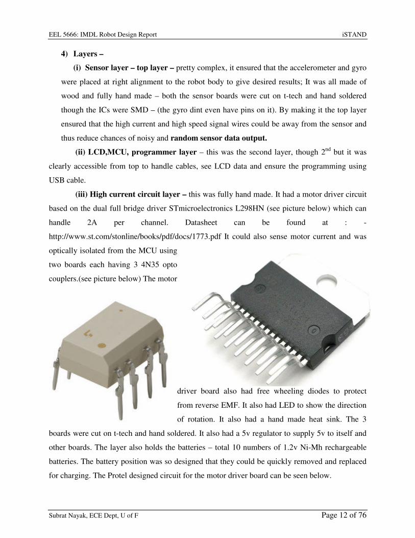
(iii) High current circuit layer – this was fully hand made. It had a motor driver circuit
based on the dual full bridge driver STmicroelectronics L298HN (see picture below) which can
handle 2A per channel. Datasheet can be found at : -
http://www.st.com/stonline/books/pdf/docs/1773.pdf It could also sense motor current and was
optically isolated from the MCU using
two boards each having 3 4N35 opto
couplers.(see picture below) The motor
driver board also had free wheeling diodes to protect
from reverse EMF. It also had LED to show the direction
of rotation. It also had a hand made heat sink. The 3
boards were cut on t-tech and hand soldered. It also had a 5v regulator to supply 5v to itself and
other boards. The layer also holds the batteries – total 10 numbers of 1.2v Ni-Mh rechargeable
batteries. The battery position was so designed that they could be quickly removed and replaced
for charging. The Protel designed circuit for the motor driver board can be seen below.

EEL 5666: IMDL Robot Design Report iSTAND
Subrat Nayak, ECE Dept, U of F Page 13 of 76
.
EEL 5666: IMDL Robot Design Report iSTAND
Subrat Nayak, ECE Dept, U of F Page 14 of 76
6.0 Actuation
I used two DC bidirectional geared motors for the actuation system. I bought two DC
bidirectional geared motors with inbuilt encoders on the back side of the motor but the motors
had too much of play and finally bought two more bigger DC bidirectional geared motors
without encoders. As observed from the conclusions made by past IMDL students, I went for
metal gears so that they do not get damaged and slip due to repeated and frequent forward and
backward motion of the motor.
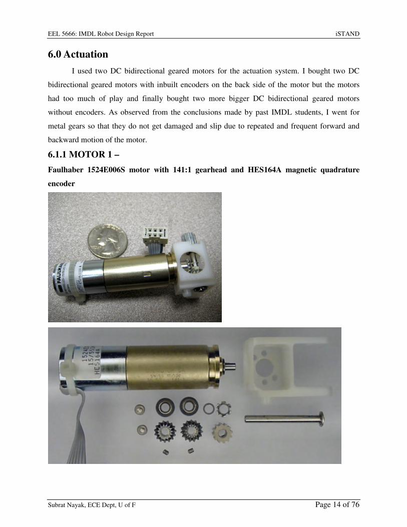
6.1.1 MOTOR 1 –
Faulhaber 1524E006S motor with 141:1 gearhead and HES164A magnetic quadrature
encoder

EEL 5666: IMDL Robot Design Report iSTAND
Subrat Nayak, ECE Dept, U of F Page 15 of 76
• It was motor rated at 6V, 12 ohms resistance (motor: 1524E006S123, where 123 is a
special order)
• 141:1 gearhead (gearhead: 15/5S141:1K832)
• max speed at 6V: approximately 80 RPM at gearhead output
EEL 5666: IMDL Robot Design Report iSTAND
Subrat Nayak, ECE Dept, U of F Page 16 of 76
• quadrate encoder with 1 line per motor revolution, or 141 x 4 = 564 counts/rev at output
shaft in 4x decoding mode (encoder: HES164A)
This little motor is the right size, speed, and torque for small wheeled mobile robots like mine.
They are used motor bought for just 7$ from robotics store bgmicro.com
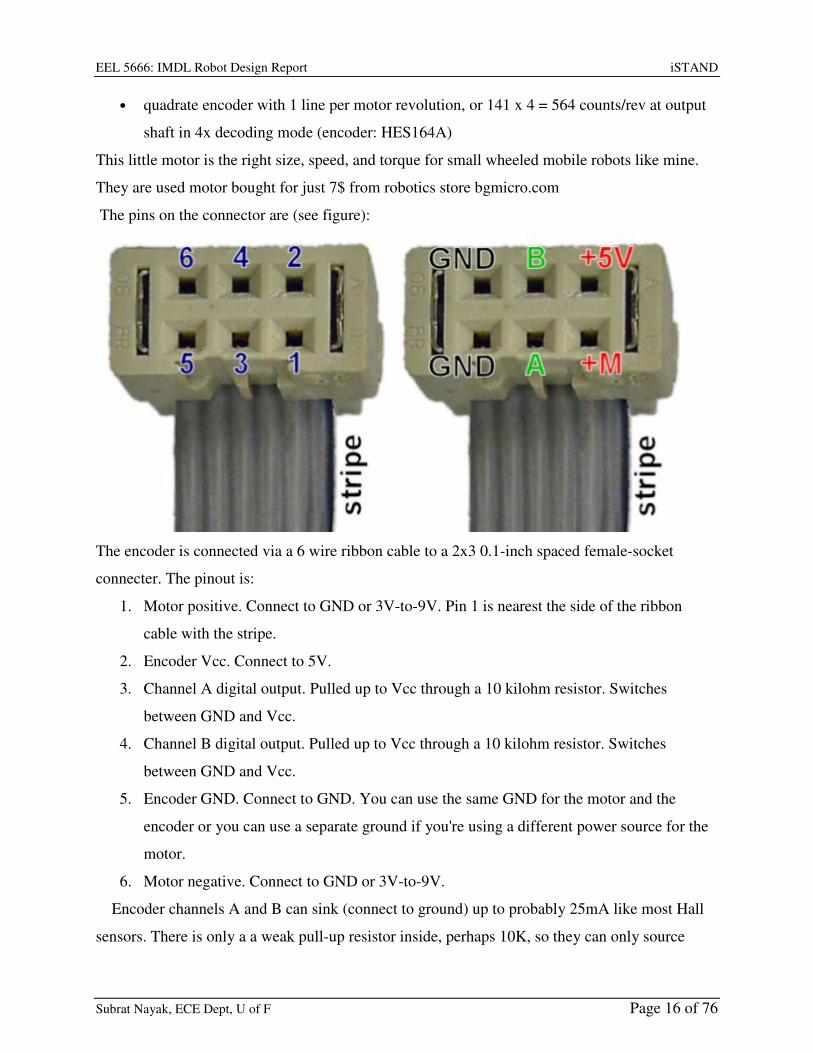
The pins on the connector are (see figure):
The encoder is connected via a 6 wire ribbon cable to a 2x3 0.1-inch spaced female-socket
connecter. The pinout is:
1. Motor positive. Connect to GND or 3V-to-9V. Pin 1 is nearest the side of the ribbon
cable with the stripe.
2. Encoder Vcc. Connect to 5V.
3. Channel A digital output. Pulled up to Vcc through a 10 kilohm resistor. Switches
between GND and Vcc.
4. Channel B digital output. Pulled up to Vcc through a 10 kilohm resistor. Switches
between GND and Vcc.
5. Encoder GND. Connect to GND. You can use the same GND for the motor and the
encoder or you can use a separate ground if you're using a different power source for the
motor.
6. Motor negative. Connect to GND or 3V-to-9V.
Encoder channels A and B can sink (connect to ground) up to probably 25mA like most Hall
sensors. There is only a a weak pull-up resistor inside, perhaps 10K, so they can only source

EEL 5666: IMDL Robot Design Report iSTAND
Subrat Nayak, ECE Dept, U of F Page 17 of 76
(connect to +5) about 2mA. If one finds the logic high signal from the encoder channel is not
close enough to +5, which can happen even due to loading by an LED, one may want to add an
external pull-up resistor from each encoder channel to +5. 470ohms is a good choice.
6.1.2 MOTOR 2 –
• S1627B by Merkle-Korff
industries, heavy duty motor,
• shaft diameter 4.80mm, length
12.9mm, flatted shaft.
• Approximately 240RPM at
12Vdc and 120RPM at 6Vdc.
• 250mA no load current. And 1
A for stall postions
• Motor diameter 30.25mm,
motor length 40.70mm,
• gear box diameter 33.60mm,
length of the gear box is
18.90mm.
• Ferrite beads to cancel EMI.
6.2.1 Wheels –
3.5 inch Dubro Wheels
6.3.1 Hub –
Hand made with simple design so that it could be quickly fabricated and also quickly removed or
attached to motor.
EEL 5666: IMDL Robot Design Report iSTAND
Subrat Nayak, ECE Dept, U of F Page 18 of 76
7.0 Sensors
iSTAND is a self balancing two wheeled robot based on the famous control system
problem called as the Inverted Pendulum. It not only aims to balance itself and remain erect but
also aims at going around wandering with obstacle avoidance like other naturally balanced
mobile robots.
To do so it needs to keep track of certain parameters about itself and its environment and
this is done by the sensors on it that act as its window to the outside. The parameters and the
respective sensor being put on iSTAND are as follows.
1) Tilt Angle – ACCELEROMETER (special sensor)
2) Rate of change of Tilt Angle – GYRO (special sensor)
3) RPM of motor – ENCODER
4) Torque delivered by the motor – CURRENT SENSOR in the MOTOR DRIVER
5) Obstacle Detection - SONAR

EEL 5666: IMDL Robot Design Report iSTAND
Subrat Nayak, ECE Dept, U of F Page 19 of 76
7.1 Tilt Angle – ACCELEROMETER
The accelerometer is a device that measures its static and dynamic acceleration along a
particular axis fixed on it. Since, the acceleration due to gravity (g) is always acting downward
and when ever there is a component of the acceleration due to gravity (g) acting along the
accelerometer’s sensing axis, it gets sensed by the accelerometer. Hence, when ever it is static
the only acceleration subject onto it is a component of g. So measuring this component and
comparing it with g, gives us the inclination or the tilt wrt vertical. Hence, It qualifies to be a tilt
sensor.
I am using the FREE SCALE MMA1260EG which is a single axis (Z axis sensitivity)
Low G (±1.5g) Micro machined Accelerometer. I got this IC as a free sample from
www.freescale.com. It comes in a 16-lead SOIC SMD package.
Some of its important features are:-
• Integral Signal Conditioning
• Linear Output
• 2nd Order Bessel Filter
• Calibrated Self-test
• EPROM Parity Check Status
• Transducer Hermetically Sealed at Wafer Level for Superior Reliability
• Robust Design, High Shock Survivability
EEL 5666: IMDL Robot Design Report iSTAND
Subrat Nayak, ECE Dept, U of F Page 20 of 76
7.1.1 Principle of Operation
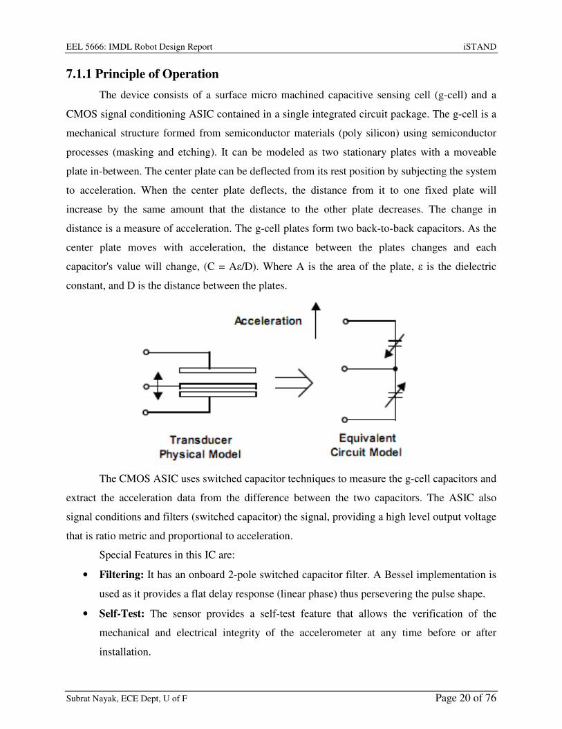
The device consists of a surface micro machined capacitive sensing cell (g-cell) and a
CMOS signal conditioning ASIC contained in a single integrated circuit package. The g-cell is a
mechanical structure formed from semiconductor materials (poly silicon) using semiconductor
processes (masking and etching). It can be modeled as two stationary plates with a moveable
plate in-between. The center plate can be deflected from its rest position by subjecting the system
to acceleration. When the center plate deflects, the distance from it to one fixed plate will
increase by the same amount that the distance to the other plate decreases. The change in
distance is a measure of acceleration. The g-cell plates form two back-to-back capacitors. As the
center plate moves with acceleration, the distance between the plates changes and each
capacitor's value will change, (C = Aε/D). Where A is the area of the plate, ε is the dielectric
constant, and D is the distance between the plates.
The CMOS ASIC uses switched capacitor techniques to measure the g-cell capacitors and
extract the acceleration data from the difference between the two capacitors. The ASIC also
signal conditions and filters (switched capacitor) the signal, providing a high level output voltage
that is ratio metric and proportional to acceleration.
Special Features in this IC are:
• Filtering: It has an onboard 2-pole switched capacitor filter. A Bessel implementation is
used as it provides a flat delay response (linear phase) thus persevering the pulse shape.
• Self-Test: The sensor provides a self-test feature that allows the verification of the
mechanical and electrical integrity of the accelerometer at any time before or after
installation.

EEL 5666: IMDL Robot Design Report iSTAND
Subrat Nayak, ECE Dept, U of F Page 21 of 76
• Status: It includes fault detection circuitry and a fault latch. The Status pin is an output
from the fault latch, OR'd with self-test, and is set high when the Parity of the EPROM
becomes odd. The fault latch can be reset by a rising edge on the self-test input.
7.1.2 Acceleration Sensing Directions:

EEL 5666: IMDL Robot Design Report iSTAND
Subrat Nayak, ECE Dept, U of F Page 22 of 76
7.1.3 Interfacing to Microcontroller
The 1K resistance and 0.1uF capacitor form a Low Pass filter was connected as shown to
provide a delay and at the same time filter high frequency noise present in the analog voltage
output before sending it to the A/D pin of the microcontroller. The PCB for this circuit was

EEL 5666: IMDL Robot Design Report iSTAND
Subrat Nayak, ECE Dept, U of F Page 23 of 76
designed using ALTIUM Designer and then was cut out on copper board by help of the T-Tech
Quick Circuit machine.
Unfortunately, there is an undesired result with the dynamic acceleration measurements.
If the platform were to be to accelerate towards the ground (e.g. falling), the increase in
acceleration appears at the accelerometer output. Hence, using the accelerometer alone as a tilt
sensor is only effective if the platform is not accelerating. In addition, any vibrations that the
motors create within the platform are also picked up by the accelerometer and cause noise in the
output. To remedy this problem, another sensor is needed.

EEL 5666: IMDL Robot Design Report iSTAND
Subrat Nayak, ECE Dept, U of F Page 24 of 76
7.1.4 Position on the Robot body
Accelerometer board

EEL 5666: IMDL Robot Design Report iSTAND
Subrat Nayak, ECE Dept, U of F Page 25 of 76
7.2 Rate of change of Tilt Angle – GYRO
A gyroscope is a device that measures angular rate/velocity. If the output of the gyro is
integrated, the position of the platform can be determined. Ideally, the gyro can be used as a tilt
sensor but there is an error introduced. Gyroscopes tend to drift over time and therefore report
inaccurate information and the running integration of the output also introduces small errors.
However, if the accelerometer and gyro were combined using a complementary filter, they
would be able to help each other. The accelerometer would correct the drift of the gyro when the
platform was not falling. The combination forms an Inertial Reference sensor.
I am using the MELEXIS MLX90609 which is a single axis (Z axis sensitivity)
ANGULAR RATE SENSOR with a full scale range of +-75 deg/sec. I got this IC as a free
sample from www.melexis.com. It comes in a CLCC32 SMD package.
Some of its important features are:-
• High resolution and dynamic range
• Both digital (SPI) and analog outputs
• Low acceleration and angular rate cross sensitivity
• Low zero rate output drift
• Cost effective and compact solution
• High-performance MEMS sensor in mono crystalline Si yielding a superior long
term behavior reliability and dynamic range
• Programmable bandwidth
• Factory set full scale range
• On chip EEPROM calibration
• Operating temperature range: -40°C to 85°C

EEL 5666: IMDL Robot Design Report iSTAND
Subrat Nayak, ECE Dept, U of F Page 26 of 76

EEL 5666: IMDL Robot Design Report iSTAND
Subrat Nayak, ECE Dept, U of F Page 27 of 76
7.2.1 Principle of Operation
The MLX90609 is a Z-axis rate-sensing device, also called yaw-rate sensing. It produces
an analog positive going output voltage for clockwise (CW) rotation around the axis normal to
the package top, i.e., clockwise when looking down at the package lid as well as a digital SPI
signal proportional to the angular rate.
The sensor is a MEMS gyroscope sensitive to Coriolis forces. To create a Coriolis force
a movement must be induced. The gyro has an actuated oscillating mechanical structure (primary
mode). The Coriolis force creates a second oscillating movement when the gyroscope
rotates (secondary mode). As Coriolis force is usually extremely weak the primary mode is

EEL 5666: IMDL Robot Design Report iSTAND
Subrat Nayak, ECE Dept, U of F Page 28 of 76
driven into resonance to keep the mechanical noise level low for the signal bandwidth
used and to have a good sensitivity. A capacitance change in the secondary mode is detected
and transformed into an output voltage by the electronic interface circuitry. The electronic
interface must convert a change in the sensor capacitance ∆C into a change in transducer
output voltage VOUT according to the following transfer equation:
The bias and gain are adjustable over temperature in order to compensate for the TC of
sensor and readout. After adjusting the bias and gain values and after setting operating mode
switches during the calibration process the transducer output voltage versus angular rate must
stay as shown in Figure above over the specified temperature range.
7.2.2 Interfacing to Microcontroller
It gives output in two formats - an analog voltage output proportional to the angular rate
and SPI digital output.
The MLX90609 can simultaneously output analog and digital signals. The analog output
signal can be fed to a microcontroller (µC) that contains an analog-to-digital converter. A
multiplexer can be used to select between the temperature and the angular rate signals.

EEL 5666: IMDL Robot Design Report iSTAND
Subrat Nayak, ECE Dept, U of F Page 29 of 76
The MLX90609 generates an internal reference voltage used for supplying the ADC,
thereby maintaining accuracy regardless of the supply voltage of the µC. As in diagram above,
The Cflt implements a first order low pass filter cascaded with an internal 4-th order SC filter.
The PCB for this circuit was designed using ALTIUM Designer and then was cut out on
copper board by help of the T-Tech Quick Circuit machine.
EEL 5666: IMDL Robot Design Report iSTAND
Subrat Nayak, ECE Dept, U of F Page 30 of 76
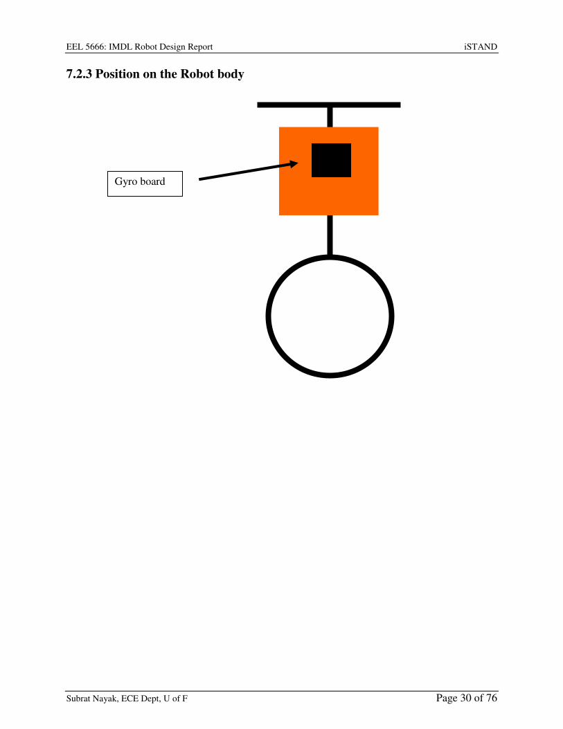
7.2.3 Position on the Robot body
Gyro board
EEL 5666: IMDL Robot Design Report iSTAND
Subrat Nayak, ECE Dept, U of F Page 31 of 76
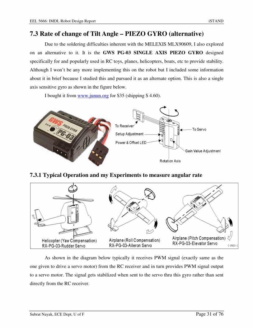
7.3 Rate of change of Tilt Angle – PIEZO GYRO (alternative)
Due to the soldering difficulties inherent with the MELEXIS MLX90609, I also explored
on an alternative to it. It is the GWS PG-03 SINGLE AXIS PIEZO GYRO designed
specifically for and popularly used in RC toys, planes, helicopters, boats, etc to provide stability.
Although I won’t be any more implementing this on the robot but I included some information
about it in brief because I studied this and pursued it as an alternate option. This is also a single
axis sensitive gyro as shown in the figure below.
I bought it from www.junun.org for $35 (shipping $ 4.60).
7.3.1 Typical Operation and my Experiments to measure angular rate
As shown in the diagram below typically it receives PWM signal (exactly same as the
one given to drive a servo motor) from the RC receiver and in turn provides PWM signal output
to a servo motor. The signal gets stabilized when sent to the servo thru this gyro rather than sent
directly from the RC receiver.

EEL 5666: IMDL Robot Design Report iSTAND
Subrat Nayak, ECE Dept, U of F Page 32 of 76
I simulated the same using a signal generator to provide PWM signal that ensures neutral
position in an un-hacked servo motor. The output was seen on a CRO, it gave exactly the same
PWM signal as output after doing the setup adjustment. But under such a condition if the Gyro is
given a angular rate about its rotation axis in one direction, the pulse widths in the output started
decreasing like the PWM signal that causes the servo to move to 0 degree position and when
given an angular rate about its rotation axis in the other direction the pulse width in the output
started decreasing like the PWM signal that causes the servo to move to 180 degree position.
Hence, I concluded that if a standard PWM signal (neutral) is given as an input to this
gyro using a 555 timer or the microcontroller, then the output contains pulses whose width
indicates the angular rate of the gyro and hence, of the body on which it is mounted. This pulse
width can be easily read by the microcontroller to determine the angular rate.

EEL 5666: IMDL Robot Design Report iSTAND
Subrat Nayak, ECE Dept, U of F Page 33 of 76
7.4 RPM of motor – ENCODERS or BACKEMF measurement
The motor that I planned to use for my robot has inbuilt dual channel optical encoders
that can be used as incremental encoder to measure the RPM of motor. They keep sending output
in form of pulses and the number of pulses per sec determines the speed of rotation of the motor
shaft. But when I changed my motor, I dint have any optical encoders, the simplest method to
determine speed was to measure the back EMF voltage which needed to be reduced through a
voltage divider circuit and then it could be measured using differential ADC features of the
ATMega128, I was working on it but due to lack of time, I couldn’t complete this feature. If
implemented this can be the simplest possible way to measure speed with minimal sensor or
hardware needed.
7.5 Torque delivered by the motor – CURRENT SENSOR on the
MOTOR DRIVER IC
I am using the STmicroelectronics L298HN which is a dual full bridge driver to drive the
DC motors on the Robot. The current passing through the motor driver is same as the current
flowing through the motor.
Normally, the current sense
pin on the L298 and ground
are shorted. But by
connecting a high wattage
low resistance between the
current sense pin on the L298
and ground, we can cause a
small voltage drop which is
proportional to the current.
This voltage can then be
scaled down using a voltage
divider circuit and fed to the
ADC on the microcontroller.
As we know that the torque delivered by a motor is proportional to the current flowing through
its windings, the torque can thus be sensed.
EN A6
EN B11
IN15
IN27
IN310
IN412
OUT12
OUT23
OUT313
OUT414
ISEN A1
ISEN B15
VS4
VSS9
GND8
L298HN
GND
R1
R2
R = 1 Ohm high Wattage
GND
Microcontroller
AD pin

EEL 5666: IMDL Robot Design Report iSTAND
Subrat Nayak, ECE Dept, U of F Page 34 of 76
7.6 Obstacle Detection – SONAR
SONAR or the Ultrasonic Range Finder
called the LV-MaxSonar- EZ1 manufactured by
www.maxbotix.com is being used for this. This
has some merits over other competitive SONAR
Sensors like the Devantech SRF05 and the
Parallax PING. It uses only one transducer to
Transmit as well as receive the Echo. Hence, the
board size is smaller and power consumption is
lesser.
EEL 5666: IMDL Robot Design Report iSTAND
Subrat Nayak, ECE Dept, U of F Page 35 of 76
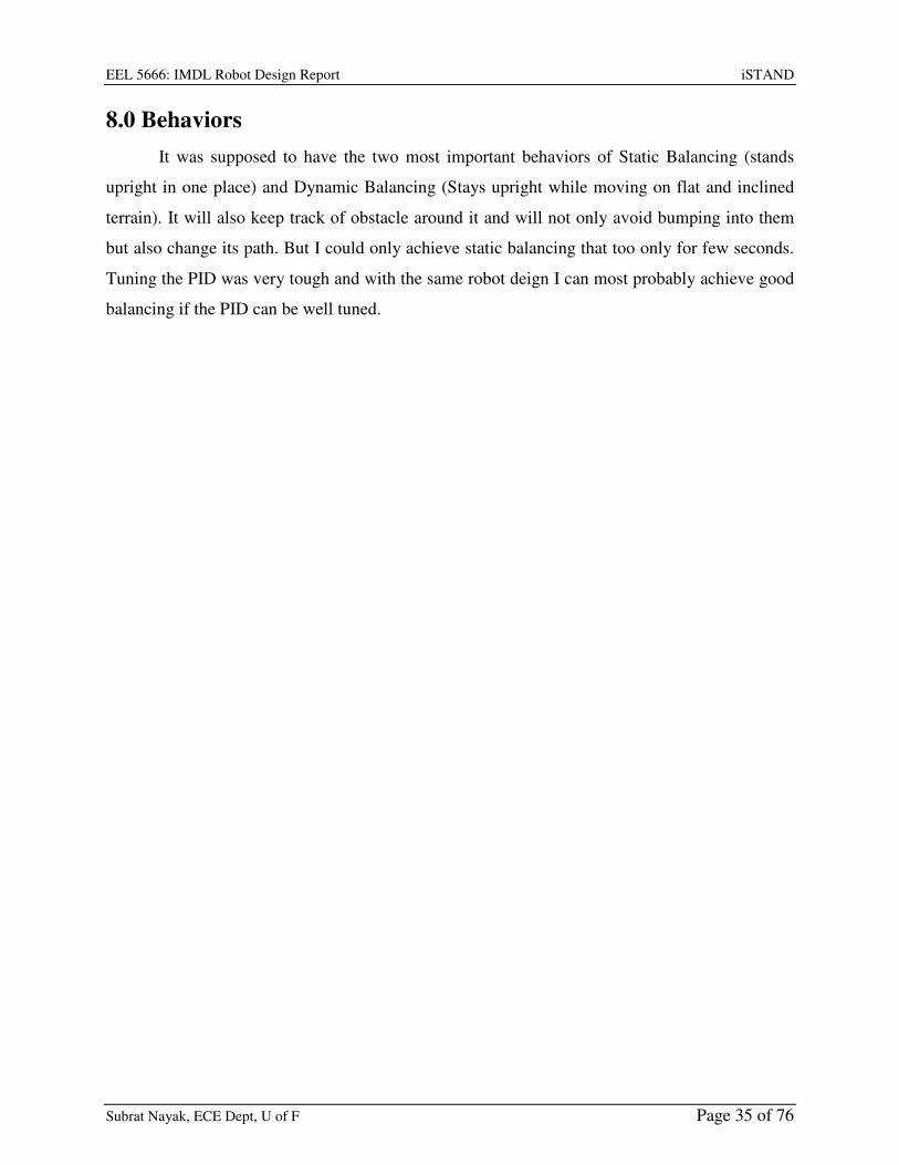
8.0 Behaviors
It was supposed to have the two most important behaviors of Static Balancing (stands
upright in one place) and Dynamic Balancing (Stays upright while moving on flat and inclined
terrain). It will also keep track of obstacle around it and will not only avoid bumping into them
but also change its path. But I could only achieve static balancing that too only for few seconds.
Tuning the PID was very tough and with the same robot deign I can most probably achieve good
balancing if the PID can be well tuned.

EEL 5666: IMDL Robot Design Report iSTAND
Subrat Nayak, ECE Dept, U of F Page 36 of 76
10.0 Conclusion
The one big thing I did realize was that my motors were powerful but had more speed
and low torque, I needed more torque on my motors for this application. I would advise that for
such a robot the platform needs to be made as soon as possible because we come across
unforeseen problems and they may demand us to redesign the base because this robot needs to be
very design efficient. I ended up making two balancing robot platforms one short and one tall but
none of them could balance well. The taller one could only balance for few seconds on its own. I
had lot of things to learn from this robot and this IMDL course. Things are not that easy as they
seem to, I feel I had much of insight and past experience with hardware so that I managed to get
everything right and reach the state of programming and tuning the PID although I made
everything myself right from hubs to circuit boards to coding. I made as much as I could, so I
learnt a lot and enjoyed this course. But I wont advise people to try making everything yourself
because to the end one realizes that time could be only saved by spending money, its always
better to get the sensors ready made so that one can quickly make the platform and focus on
coding and fine tuning.
10.1.1 Components vs Effort
BOLD LINES SHOW MY EFFORT – hence, I nearly made everything that could be hand
made for this project. – I wish I had time to make an ATmega 128 board like the maverick
IIb board.
1) 3.5 inch wheels – ready made
2) Hubs – fabricated in machine shop
3) Motors – 12v PMDC - ready made
4) Motor mounts – cut on T-tech
5) Wheel Encoders – managed with software to read the back EMF
6) Threaded rods – ready made
7) 3 layer base – complex 3D planes – cut on T-tech
8) MCU Layer – MCU/LCD/programmer – ready made
9) Power circuit Layer –
(i) Motor driver - cut on T-tech and hand soldered
(ii) Heat sink – hand made in workshop
(iii) Opto-coupler – cut on T-tech and hand soldered –
EEL 5666: IMDL Robot Design Report iSTAND
Subrat Nayak, ECE Dept, U of F Page 37 of 76
(iv) Batteries – ready made
10) Sensor Layer – 2 planes –
(i) Accelerometer board – cut on t-tech and hand-soldered (SMD chip)
(ii) Gyro Board – cut on T-tech and hand soldered (SMD chip – no pins – really
challenging but I did it well and learnt that it’s actually very very easy)
(iii) Sonar – ready made
In this I would say the biggest focus should be on choosing the right accelerometer
sensor, right gyro sensor and right motors. Driving a DC motor is bit more complex than driving
Servos. For Servo, one doesn’t need a motor driver, they come with inbuilt motor driver, just
feed a pwm signal and it starts running but they are not strong and the speed control is not linear.
For DC motors, the biggest focus needs to be on getting the right kind of motor drivers, using
opto-couplers to isolate the driver from board, using right capacitors to absorb noise coming
from the motor driver, use of free wheeling diode to protect from reverse voltage surge when the
motor quickly reverses direction and heat sinking. I did all of them and my motor driver also had
features of measuring the current through the motor (to measure torque) and backemf across the
motor (to measure speed). I tried my best to keep the cost low and used as much free stuff as I
could, see the expense table in Documentation.
In future I would keep pursing this project and make the two robots balance and if
possible make an algorithm which uses Machine learning to calibrate the PID constants on its
own so that the same software can be run on 2 wheeled balancing robots of various sizes and
structures.
My words about the IMDL course is that IMDL is addictive, I love the work we do in
IMDL and I devoted too much time into this and could not manage time and messed up other
courses. I finally could not even end up having enough time for making the robot do as it was
aimed to do. I not only did work on my robot but also helped and guided many students in class,
I made protel boards of some and the biggest work I felt happy of doing was making a sensorfro
fellow classmate that could sense a wire carrying current though it. It’s normally used as a
wireless fence for pets, the sensor senses a long wire (acts as fence) carrying high frequency AC
though it and shocks the pet whenever it tries to cross the fence. This was supposed to be used
for line following, in which the robot senses the wire moves along it. The sensor used to emit
some beeps which was diffcult to detect and the shocking signal was of the order of > 100v and

EEL 5666: IMDL Robot Design Report iSTAND
Subrat Nayak, ECE Dept, U of F Page 38 of 76
could not be used directly. I liked this sensor and the application, we tried a lot to sense the
sound but having another sensor when we have a sensor dint seem sensible to me and it was
difficult to detect the sound without getting disturbed by other sounds coming from the
surroundings, So I decided to tap the shocking voltage output and make it usable, I got shocked
couple of times but finally I find out how to get rid of that, I opticallt isolated it and shaped the
input signal from the senor into thick pulses using a 555 times in monostable mode and it worked
great. It took lot of time to get this done after some trials. I did this in the last week of class when
te fellow classmate badly needed a sensor and I was running short of time. It was fun and I
enjoyed it.
The biggest problem I believe students face is in getting the right parts, getting them at
good prices and getting them quickly. Hunting for parts in online robot stores over the internet
becomes addictive and I remember whenever I used to sit to look for parts, time used to fly like
anything and I used to enjoy knowing about robot parts, how they work, there specifications but
this is were one needs to prioritize and keep control. One needs to draw a margin for his robot
and stick to the features and not try to do more and more. Thus decisions for parts needs to be
done in the first month and should get them all in hand worst case by the second month. Don’t
just blindly follow what the TAs suggest for parts, do keep their suggestions in mind but also
look over the internet and find the best and cheapest options for yourself. This is what I did right
in the beginning when I blindly ordered for the Maverick board. The maverick board costs 100$
but I later found more or less similar board at around half the price. 1) Ths ATmega 128 board
made by http://www.maximumrobotics.com comes for just 60$. (same as maverick board) 2)
The ATmega128 board available at http://www.sparkfun.com comes for < 40$ (version1 – with
isp + jtag but no MAX232 chip) and 85$ (version2 – same as maverick board) I hope future
students in IMDL make best use of this piece of information.Similarly, For the programmer, we
were suggested to buy the JTAG from http://microcontrollershop.com but I found that the same
website also sells a JTAG+ISP(both one one) programmer for exactly same price. Students
should also explore on getting as much free sample as they can. Chip manufactures like Fresscale
and STmicrcelectronics respond quickly and send free samples. I even got free gyro samples
(each chip worth 23$) from MELEXIS. Hence, it always a good step to try for free samples. Rest
one has to decide between time and money sometimes is better to spend to get the right thing and
avoid hassles.

EEL 5666: IMDL Robot Design Report iSTAND
Subrat Nayak, ECE Dept, U of F Page 39 of 76
I have one last experience in IMDL to mention. I feel IMDL is easier for Electrical
students but not that easy for Mechanical and Computer Science students. Even at the end of
course what I saw is that many of my fellow classmates could not program much simply because
they dint knew even the basics of programming the ATmega128. and it was late when they tried
their best to program it on their own towards the end, many got their programs written by others
or just used the sample codes given by the TA and professors without understanding how things
worked and how to integrate pieces of code. Mist of them dint ever look into the Atmega128
datasheet because was 400 pages while they actually needed to learn very few pages out of it as
per need. Somehow everybody managed and the TAs patiently helped the students as best as
they could. I remember that one of the TA had to teach how a while loop works to one of the
students. For all this my humble suggestion is that right in the beginning of the semester, when
the TAs were relatively free, they could have taken combined classes for students and taught
them basics of AVR programming in detail – like how I/O ports work, how ADC works, how
TIMERS work, how interrupts work, etc than just giving the code and explaining code to
students one by one on a first come first serve basis in the Lab.

EEL 5666: IMDL Robot Design Report iSTAND
Subrat Nayak, ECE Dept, U of F Page 40 of 76
11.0 Documentation
Parts used and Expenses:-
Note: I ended up getting much more parts than what I actually needed or used, here I have only
mentioned what was used on one robot.
Parts Source approximate Price without shipping
Atmega128 Mavric Board www.bdmicro.com/mavric-iib/ $100
AVR JTAG+ISP programmer microcontrollershop.com $59
LCD (24 X 2) www.bgmicro.com $4
2 DC motors - www.bgmicro.com $ 7 each = total $14
6 Opto couplers www.bgmicro.com 10 cents each = total$ 0.60
6 BC547 transistors www.bgmicro.com 6 cents each = total$ 0.36
4 LEDs www.bgmicro.com 8 cents each = total $0.32
Switch www.bgmicro.com $1
2 Stackable blocks 2 pole www.bgmicro.com 36 cents each = total $0.72
Heat shrink tube www.bgmicro.com $1
7805 voltage regulator www.bgmicro.com $0.40
2 1Ohm 15 W Resistance www.bgmicro.com $1 each = total $2
4 3feet threaded rods Lowes $ 2 each = total $8
2 3.5inch dubro wheels HobbyTownUSA, Gainesville $ 3 each = total $6
12 NiMh Battery and Smart charger www.batteryspace.com Combo for total = $25
Wood IMDL Lab free
Copper boards - PCB IMDL Lab free
Small components like headers, wires, capacitors, resistors, bump switches,diodes, battery pack etc etc IMDL Lab free
Nuts, bolts, washers, aluminum pieces for heat sink and motor hub Ron’s Student workshop free
MMA1260EG accelerometer www.freescale.com Free sample
MLX90609 gyro www.melexis.com Free sample
L298HN dual motor driver www.st.com Free sample
Lots and Lots of Time Subrat Nayak – Spring 2008 Invaluable
The most expensive thing I bought was the Mavrick board, I could have save around 60$
if I had looked on the internet and bought the spark fun board for 40$. www.bgmicro.com is a
great surplus store where we get cheap stuff and all in one place so that you order together and
save on shipping.

EEL 5666: IMDL Robot Design Report iSTAND
Subrat Nayak, ECE Dept, U of F Page 41 of 76
Special Thanks
1) Dr.Arroyo - for his loud lectures and the experiences that he used to share in the class. I
wish to work more with him.
2) Dr Schwartz – for inspiring me, I wish to work more with him.
3) Adam Barnett – He has been most helpful, he worked hard for me and cut so many
copper boards and wood for me on the T-tech. For trusting me and letting me work after
lab hours in the lab in his absence. I don’t think I could have done much without those
extra hours. He has also done so many extra lab hours for us. He never missed
appreciating my work whenever he saw me do good work.
4) Sara Keen – for doing extra lab hours for us towards the end and trusting us and letting us
work in the lab after her lab hours. I don’t think I could have done much without those
extra hours in which I could focus and work without the tension of hurrying up as the lab
may get closed.
5) Mike Pridgen – for his guidance and suggestions and for lending me his maverick board
for a while. He knows a lot.
6) Ron Brown – letting me work in his workshop, he was very helpful and at times even
waited up to 30 mins after workshop hours for us. He trusted me and let me use any tool
that I ever asked for.
7) Tarandeep Brar and Rohan Pais – fellow classmates and my close friends who inspired
me and were always with me at good times and bad times during the IMDL, it was great
working with them. They were willing to experiment and try out new things all the time.
Tarandeep is great in coding and suggested me whenever I had any doubts or confusions.
8) Koushik Kalyanaraman – fellow IMDL class mate, he kept the lab open by working in
the lab and being around over one of the weekends by end of the classes from Friday
evening 5 pm to Sunday morning 7 am and we all took breaks went home and came back
but he kept on hanging in the lab. He inspired me and that whole weekend work in the lab
was the most useful time for me.
9) Kim Wright – fellow IMDL class mate, for letting me work on her dog-shocking sensor, I
really liked the sensor and she trusted me and gave it to me to experiment and work on it.
10) Andres Vargas - fellow IMDL class mate who was also making a balancing robot. He
never gave up and kept trying hard till last second. He inspired me to keep working till

EEL 5666: IMDL Robot Design Report iSTAND
Subrat Nayak, ECE Dept, U of F Page 42 of 76
last second. When the IMDL lab was closed, he was there working in the MIL and
invited me and informed me that I could also work in the MIL.
11) Steven Buss - fellow IMDL class mate, for teaching me and helping me in fabricating the
motor hub on the lathe machine in Ron’s workshop
12) Nicholas Wulf - fellow IMDL class mate for guiding me in some issues like interrupt
handling of the AVR.
13) Brian Kuschak – he made successful balancing robot, he was very prompt ins responding
to some my queries and advised me on some issues.
14) Al Ogden – trying hard to find a very small Allen Key to open my motor gear box.
EEL 5666: IMDL Robot Design Report iSTAND
Subrat Nayak, ECE Dept, U of F Page 43 of 76
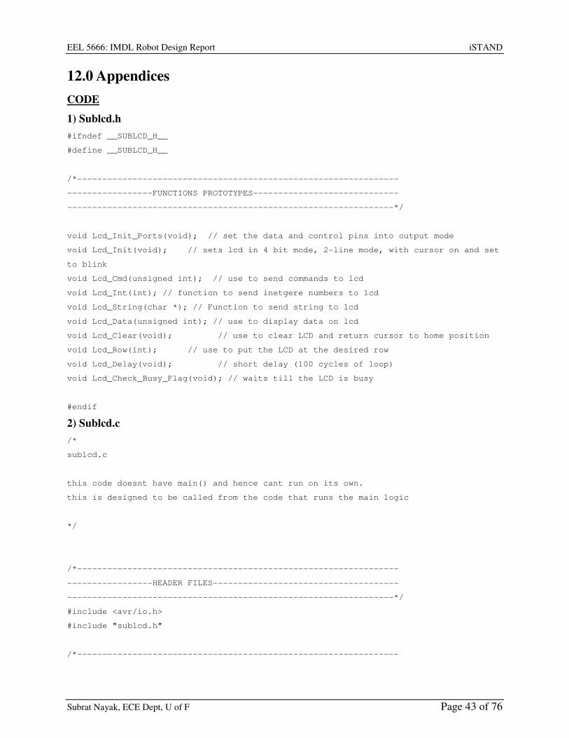
12.0 Appendices
CODE
1) Sublcd.h
#ifndef __SUBLCD_H__
#define __SUBLCD_H__
/*----------------------------------------------------------------
-----------------FUNCTIONS PROTOTYPES-----------------------------
-----------------------------------------------------------------*/
void Lcd_Init_Ports(void); // set the data and control pins into output mode
void Lcd_Init(void); // sets lcd in 4 bit mode, 2-line mode, with cursor on and set
to blink
void Lcd_Cmd(unsigned int); // use to send commands to lcd
void Lcd_Int(int); // function to send inetgere numbers to lcd
void Lcd_String(char *); // Function to send string to lcd
void Lcd_Data(unsigned int); // use to display data on lcd
void Lcd_Clear(void); // use to clear LCD and return cursor to home position
void Lcd_Row(int); // use to put the LCD at the desired row
void Lcd_Delay(void); // short delay (100 cycles of loop)
void Lcd_Check_Busy_Flag(void); // waits till the LCD is busy
#endif
2) Sublcd.c
/*
sublcd.c
this code doesnt have main() and hence cant run on its own.
this is designed to be called from the code that runs the main logic
*/
/*----------------------------------------------------------------
-----------------HEADER FILES-------------------------------------
-----------------------------------------------------------------*/
#include <avr/io.h>
#include "sublcd.h"
/*----------------------------------------------------------------

EEL 5666: IMDL Robot Design Report iSTAND
Subrat Nayak, ECE Dept, U of F Page 44 of 76
-------------CONNECTION BETWEEN LCD AND ATMEGA128-----------------
-----------------------------------------------------------------*/
#define LCD_DATA_DDR DDRC
#define LCD_DATA_PORT PORTC
#define LCD_DATA_PIN PINC
#define LCD_Data_Pin7 7
#define LCD_Data_Pin6 6
#define LCD_Data_Pin5 5
#define LCD_Data_Pin4 4
#define UPPER_NIBBLE_MASK 0XF0 // 0xF0 = 0b11110000
#define LOWER_NIBBLE_MASK 0XF0 // 0x0F = 0b00001111
#define SUB 27
/*
4-bit mode of operation
--------------------------------------
PortC bit 7 : LCD data bit 7 (MSB)
PortC bit 6 : LCD data bit 6
PortC bit 5 : LCD data bit 5
PortC bit 4 : LCD data bit 4 (LSB)
*/
#define LCD_CONTROL_DDR DDRC
#define LCD_CONTROL_PORT PORTC
#define LCD_Enable_Pin 3
#define LCD_ReadWrite_Pin 2
#define LCD_RegSelect_Pin 1
/*
PortC bit 3 : LCD enable pin (clock)
PortC bit 2 : LCD R/W (read / write) signal
PortC bit 1 : LCD RS (register select) pin
PortC bit 0 : (not connected)
*/
/*----------------------------------------------------------------
-------------CONTROL BITS OF LCD --------------------------------
-----------------------------------------------------------------*/
EEL 5666: IMDL Robot Design Report iSTAND
Subrat Nayak, ECE Dept, U of F Page 45 of 76
#define LCD_Set_Enable LCD_CONTROL_PORT|=_BV(LCD_Enable_Pin)
#define LCD_Clear_Enable LCD_CONTROL_PORT&=~_BV(LCD_Enable_Pin)
#define LCD_Write LCD_CONTROL_PORT&=~_BV(LCD_ReadWrite_Pin)
#define LCD_Read
LCD_CONTROL_PORT|=_BV(LCD_ReadWrite_Pin)
#define LCD_Select_InstructionRegister LCD_CONTROL_PORT&=~_BV(LCD_RegSelect_Pin)
#define LCD_Select_DataRegister LCD_CONTROL_PORT|=_BV(LCD_RegSelect_Pin)
/*---------------------------------------------------------------------
----------FUNCTION PROTOTYPES - its rather written in the sublcd.h-------
-----------------------------------------------------------------*/
/*
void Lcd_Init_Ports(void); // set the data and control pins into output mode
void Lcd_Init(void); // sets lcd in 4 bit mode, 2-line mode, with cursor on and set
to blink
void Lcd_Cmd(unsigned int); // use to send commands to lcd
void Lcd_Int(int); // function to send inetgere numbers to lcd
void Lcd_String(char *); // Function to send string to lcd
void Lcd_Data(unsigned int); // use to display data on lcd
void Lcd_Clear(void); // use to clear LCD and return cursor to home position
void Lcd_Row(int); // use to put the LCD at the desired row
void Lcd_Delay(void); // short delay (100 cycles of loop)
void Lcd_Check_Busy_Flag(void); // waits till the LCD is busy
*/
/*----------------------------------------------------------------
----------------MAIN FUNCTION--------------------------------------
-----------------------------------------------------------------*/
/*int main(void)
{
Lcd_Init_Ports(); // set the data and control pins into output mode
Lcd_Init(); // set lcd in 4 bit mode, 2-line mode, with cursor on and set to
blink
Lcd_String("yuhooooo"); // if your LCD is wired up correctly, you will see this
text

EEL 5666: IMDL Robot Design Report iSTAND
Subrat Nayak, ECE Dept, U of F Page 46 of 76
// on it when you power up your Micro-controller
board.
Lcd_Row(1);
Lcd_String("Good luck! :)");
return 0;
}
*/
/*----------------------------------------------------------------
-----------------FUNCTIONS TO INITIALIZE PORTS FOR LCD------------
-----------------------------------------------------------------*/
void Lcd_Init_Ports(void)
{
LCD_DATA_DDR |=
(_BV(LCD_Data_Pin7)|_BV(LCD_Data_Pin6)|_BV(LCD_Data_Pin5)|_BV(LCD_Data_Pin4));
// set 4 MSnibble bits on DDRC to make the respective pins of data portas output
(0b11110000)
LCD_CONTROL_DDR |=
(_BV(LCD_Enable_Pin)|_BV(LCD_RegSelect_Pin)|_BV(LCD_ReadWrite_Pin));
//set selected bits of DDRC to make the respective pins of control port as output
(0b00000111)
LCD_CONTROL_PORT&=~(_BV(LCD_Enable_Pin)|_BV(LCD_RegSelect_Pin)|_BV(LCD_ReadWrite_Pin))
;
//clearing the 3 control bits at starting
}
/*----------------------------------------------------------------
------------FUNCTION TO INITIATE LCD -----------------------------
-----------------------------------------------------------------*/
void Lcd_Init(void)
{
Lcd_Cmd(0x33); // writing 0x33 followed by
Lcd_Cmd(0x32); // 0x32 puts the LCD in 4-bit mode
Lcd_Cmd(0x28); // writing 0x28 puts the LCD in 2-line mode

EEL 5666: IMDL Robot Design Report iSTAND
Subrat Nayak, ECE Dept, U of F Page 47 of 76
Lcd_Cmd(0x0F); // writing 0x0F turns the display on, curson on, and puts the
cursor in blink mode
Lcd_Cmd(0x01); // writing 0x01 clears the LCD and sets the cursor to the home
(top left) position
//LCD is on... ready to write
}
/*----------------------------------------------------------------
------------FUNCTION TO SEND COMMAND TO LCD ----------------------
-----------------------------------------------------------------*/
void Lcd_Cmd( unsigned int cmd_data )
{
unsigned int temp_data1 = 0;
unsigned int temp_data2 = 0;
LCD_Select_InstructionRegister; // only line that is differnt compared to
Lcd_Data function
LCD_Write;
temp_data1 = LCD_DATA_PORT & 0b00001111;
// temp_data1 = [0000][lower nibble of LCD_DATA_PORT]
temp_data2 = cmd_data & 0b11110000;
// temp_data2 = [upper nibble of DATA][0000]
Lcd_Check_Busy_Flag();
LCD_DATA_PORT = temp_data2 | temp_data1;
// LCD_DATA_PORT = [upper nibble of DATA] [lower nibble of LCD_DATA_PORT]
// thus, we write the upper nibble of DATA to LCD_DATA_PORT.7 to
LCD_DATA_PORT.4
// while the lower 4 bits on LCD_DATA_PORT remains preserved
LCD_Set_Enable;
Lcd_Delay();
LCD_Clear_Enable; // data gets latched onto the LCD register at the high to
low edge on enable pin
temp_data1 = LCD_DATA_PORT & 0b00001111;
// temp_data1 = [0000][lower nibble of LCD_DATA_PORT]
temp_data2 = (cmd_data << 4) & 0b11110000;
EEL 5666: IMDL Robot Design Report iSTAND
Subrat Nayak, ECE Dept, U of F Page 48 of 76
// shift the bits in DATA to the left 4 times puts the lower nibble into the
upper 4 bits
// temp_data2 = [lower nibble of DATA][0000]
Lcd_Check_Busy_Flag();
LCD_DATA_PORT = temp_data2 | temp_data1;
// LCD_DATA_PORT = [lower nibble of DATA] [lower nibble of LCD_DATA_PORT]
// thus, we write the lower nibble of DATA to LCD_DATA_PORT.7 to
LCD_DATA_PORT.4
// while the lower 4 bits on LCD_DATA_PORT remains preserved
LCD_Set_Enable;
Lcd_Delay();
LCD_Clear_Enable;// data gets latched onto the LCD register at the high to low
edge on enable pin
}
/*----------------------------------------------------------------
------------FUNCTION TO SEND STRING To LCD ----------------------
-----------------------------------------------------------------*/
void Lcd_String(char *a)
{
/*
This function writes a string to the LCD. LCDs can only print one character at a
time so we need to
print each letter or number in the string one at a time. This is accomplished by
creating a pointer to
the beginning of the string (which logically points to the first character). It is
important to understand
that all strings in C end with the "null" character which is interpreted by the
language as a 0. So to print
an entire string to the LCD we point to the beginning of the string, print the
first letter, then we increment
the pointer (thus making it point to the second letter), print that letter, and
keep incrementing until we reach
the "null" character". This can all be easily done by using a while loop that
continuously prints a letter and
increments the pointer as long as a 0 is not what the pointer points to.
*/
EEL 5666: IMDL Robot Design Report iSTAND
Subrat Nayak, ECE Dept, U of F Page 49 of 76
while (*a != 0)
{
Lcd_Data((unsigned int) *a); // display the character that pointer (a) is
pointing to
a++; // increment a
}
}
//----------------------------------------------------------------
//------------FUNCTION TO SEND INTeger To LCD ----------------------
//-----------------------------------------------------------------
/*
void Lcd_Int(int value)
{
//This routine will take an integer and display it in the proper order on
//your LCD. Thanks to Josh Hartman (IMDL Spring 2007) for writing this in lab
int temp_val;
int x = 10000; // since integers only go up to 32768, we only need to worry
about
// numbers containing at most a ten-thousands place
while (value / x == 0) // the purpose of this loop is to find out the largest
position (in decimal)
{ // that our integer contains. As soon as we get a non-zero
value, we know
x/=10; // how many positions there are int. the int and x will be
properly initialized to the largest
} // power of 10 that will return a non-zero value when our
integer is divided by x.
while (value > 0) // this loop is where the printing to the LCD takes
place. First, we divide
{ // our integer by x (properly initialized by the last
loop) and store it in

EEL 5666: IMDL Robot Design Report iSTAND
Subrat Nayak, ECE Dept, U of F Page 50 of 76
temp_val = value / x; // a temporary variable so our original value is
preserved. Next we subtract the
value -= temp_val * x; // temp. variable times x from our original value.
This will "pull" off the most
Lcd_Data(temp_val + 0x30); // significant digit from our original integer but
leave all the remaining digits alone.
// After this, we add a hex 30 to our temp. variable
because ASCII values for integers
x /= 10; // 0 through 9 correspond to hex numbers 30 through 39.
We then send this value to the
} // LCD (which understands ASCII). Finally, we divide x by
10 and repeat the process
// until we get a zero value (note: since our value is an
integer, any decimal value
// less than 1 will be truncated to a 0)
}
*/
void Lcd_Int(int value)
{
int temp_val;
int x = 10000;
int nLen = 0;
while (value / x == 0)
{
x/=10;
nLen++;
}
nLen = 5 - nLen;
while (nLen--)
{
temp_val = value / x;
value -= temp_val * x;
Lcd_Data(temp_val + 0x30);
x /= 10;
}
}
EEL 5666: IMDL Robot Design Report iSTAND
Subrat Nayak, ECE Dept, U of F Page 51 of 76
/*----------------------------------------------------------------
------------FUNCTION TO SEND DATA TO LCD ----------------------
-----------------------------------------------------------------*/
void Lcd_Data(unsigned int disp_data)
{
unsigned int temp_data1 = 0;
unsigned int temp_data2 = 0;
LCD_Select_DataRegister; // only line that is differnt compared to Lcd_Cmd
function
LCD_Write;
temp_data1 = LCD_DATA_PORT & 0b00001111;
// temp_data1 = [0000][lower nibble of LCD_DATA_PORT]
temp_data2 = disp_data & 0b11110000;
// temp_data2 = [upper nibble of DATA][0000]
Lcd_Check_Busy_Flag();
LCD_DATA_PORT = temp_data2 | temp_data1;
// LCD_DATA_PORT = [upper nibble of DATA] [lower nibble of LCD_DATA_PORT]
// thus, we write the upper nibble of DATA to LCD_DATA_PORT.7 to
LCD_DATA_PORT.4
// while the lower 4 bits on LCD_DATA_PORT remains preserved
LCD_Set_Enable;
Lcd_Delay();
LCD_Clear_Enable;// data gets latched onto the LCD register at the high to low
edge on enable pin
temp_data1 = LCD_DATA_PORT & 0b00001111;
// temp_data1 = [0000][lower nibble of LCD_DATA_PORT]
temp_data2 = (disp_data << 4) & 0b11110000;
// shift the bits in DATA to the left 4 times puts the lower nibble into the
upper 4 bits
// temp_data2 = [lower nibble of DATA][0000]
Lcd_Check_Busy_Flag();
LCD_DATA_PORT = temp_data2 | temp_data1;
// LCD_DATA_PORT = [lower nibble of DATA] [lower nibble of LCD_DATA_PORT]
// thus, we write the lower nibble of DATA to LCD_DATA_PORT.7 to
LCD_DATA_PORT.4
// while the lower 4 bits on LCD_DATA_PORT remains preserved
LCD_Set_Enable;

EEL 5666: IMDL Robot Design Report iSTAND
Subrat Nayak, ECE Dept, U of F Page 52 of 76
Lcd_Delay();
LCD_Clear_Enable;// data gets latched onto the LCD register at the high to low
edge on enable pin
}
/*----------------------------------------------------------------
------------ FUNCTION TO CLEAR LCD SCREEN ------------------------
-----------------------------------------------------------------*/
void Lcd_Clear() // this function clears the LCD and sets the cursor to the home
(upper left) position
{
Lcd_Cmd(0x01);
}
/*----------------------------------------------------------------
------------ FUNCTION TO SELECT ROW ON LCD SCREEN ---------------
-----------------------------------------------------------------*/
void Lcd_Row(int row) // this function moves the cursor to the beginning of the
specified row without changing
// any of
the current text on the LCD.
{
switch(row)
{
case 0: Lcd_Cmd(0x02);
case 1: Lcd_Cmd(0xC0);
}
}

EEL 5666: IMDL Robot Design Report iSTAND
Subrat Nayak, ECE Dept, U of F Page 53 of 76
/*----------------------------------------------------------------
------------ FUNCTION TO HAVE A SHORT DELAY ----------------------------
-----------------------------------------------------------------*/
void Lcd_Delay() // delay for 100 clock cycles
{
long int ms_count = 0;
while (ms_count < 100)
{
ms_count++;
}
}
/*----------------------------------------------------------------
------------ FUNCTION TO CHECK IF THE LCD IS BUSY -----------------
-----------------------------------------------------------------*/
void Lcd_Check_Busy_Flag()
{
LCD_DATA_DDR &= ~(_BV(LCD_Data_Pin7)); //clear 7th bit of DDRC to make it input pin
(0b01111111)
LCD_DATA_PORT |= _BV(LCD_Data_Pin7); //set the 7th bit on portC to enable the pull-up
resistor (0b10000000)
LCD_Read;
LCD_Select_InstructionRegister;
do
{
LCD_Clear_Enable;
Lcd_Delay();
LCD_Set_Enable; // data gets read from the LCD register at the low to high edge
on enable pin
}
while((LCD_DATA_PIN & _BV(LCD_Data_Pin7)) >> (LCD_Data_Pin7));
LCD_DATA_DDR |= _BV(LCD_Data_Pin7); //set the 7th bit of DDRC to make it output pin
(0b10000000)
}

EEL 5666: IMDL Robot Design Report iSTAND
Subrat Nayak, ECE Dept, U of F Page 54 of 76
3) Subadc.h
#ifndef __SUBADC_H__
#define __SUBADC_H__
/*----------------------------------------------------------------
-----------------FUNCTIONS PROTOTYPES-----------------------------
-----------------------------------------------------------------*/
void ADC_Init_Ports(void); // set the pins to input mode to recive the Analog input
void ADC_Init(int mode); //Enable ADC, select mode, select prescaler clk, select
Vref, select channel
void ADC_Start_Conversion(void); //TO Start ADC conversion
int ADC_Conversion_Complete(void); // to check if adconversion completed only for
single conversion mode
void ADC_Select_Channel(int channel); //to select channel for adc
#endif
4) Subadc.c
/*
subadc.c
to read the analog volatage input
this code doesnt have main() and hence cant run on its own.
this is designed to be called from the code that runs the main logic*/
/*----------------------------------------------------------------
-----------------HEADER FILES-------------------------------------
-----------------------------------------------------------------*/
#include <avr/io.h>
#include "subadc.h"
/*----------------------------------------------------------------
-------------CONNECTION for ADC input AND ATMEGA128-----------------
-----------------------------------------------------------------*/
#define ADC_DATA_DDR DDRF
#define ADC_DATA_PORT PORTF
#define ADC_Data_Pin0 0
#define ADC_Data_Pin1 1
#define ADC_Data_Pin2 2
#define ADC_Data_Pin3 3

EEL 5666: IMDL Robot Design Report iSTAND
Subrat Nayak, ECE Dept, U of F Page 55 of 76
/*----------------------------------------------------------------
----------ADMUX - ADC CHANNEL and REF SELECTION REGISTER--------------
-----------------------------------------------------------------*/
#define ADC_ADMUX_REFS1 7
#define ADC_ADMUX_REFS0 6
#define ADC_ADMUX_ADLAR 5
#define ADC_ADMUX_MUX4 4
#define ADC_ADMUX_MUX3 3
#define ADC_ADMUX_MUX2 2
#define ADC_ADMUX_MUX1 1
#define ADC_ADMUX_MUX0 0
/*----------------------------------------------------------------
----------ADCSRA - ADC STATUS and CONTROL REGISTER--------------
-----------------------------------------------------------------*/
#define ADC_ADCSRA_ADEN 7
#define ADC_ADCSRA_ADSC 6
#define ADC_ADCSRA_ADFR 5
#define ADC_ADCSRA_ADIF 4
#define ADC_ADCSRA_ADIE 3
#define ADC_ADCSRA_ADPS2 2
#define ADC_ADCSRA_ADPS1 1
#define ADC_ADCSRA_ADPS0 0
/*----------------------------------------------------------------
-----------------REASULT OF THE ADC-----------------------------
-----------------------------------------------------------------*/
#define ADC_RESULT_HIGH_BYTE ADCH
#define ADC_RESULT_LOW_BYTE ADCL
/*----------------------------------------------------------------
-------------CONTROL BITS OF ADC --------------------------------
-----------------------------------------------------------------*/
#define ADC_Set_Enable ADCSRA|=_BV(ADC_ADCSRA_ADEN) // enables ADC by setting bit 7
(ADEN) in the ADCSRA
#define ADC_Start_Conversion_Step ADCSRA|=_BV(ADC_ADCSRA_ADSC) // start a conversion
by setting ADSC (bit 6) in ADCSRA
#define ADC_Select_FreeRunMode ADCSRA|=_BV(ADC_ADCSRA_ADFR)// enables free running
mode by setting the 5th bit (ADFR) in ADCSRA
#define ADC_Select_SingleConvMode ADCSRA&=~(_BV(ADC_ADCSRA_ADFR))// enables single
conversion mode by clearing the 5th bit (ADFR) in ADCSRA
EEL 5666: IMDL Robot Design Report iSTAND
Subrat Nayak, ECE Dept, U of F Page 56 of 76
#define ADC_Select_Prescaler_DivideBy128 ADCSRA = ((ADCSRA & 0b11111000) | 0b00000111)
// selects divide by 64 for clock prescaler - 111 on the ADPS2, ADPS1 and ADPS0
respectively
// hence, set 2nd and 1st bit abd clears 0th bit
#define ADC_Select_Prescaler_DivideBy64 ADCSRA = ((ADCSRA & 0b11111000) | 0b00000110)
// selects divide by 64 for clock prescaler - 110 on the ADPS2, ADPS1 and ADPS0
respectively
// hence, set 2nd and 1st bit abd clears 0th bit
#define ADC_Select_Prescaler_DivideBy32 ADCSRA = ((ADCSRA & 0b11111000) | 0b00000101)
// selects divide by 64 for clock prescaler - 101 on the ADPS2, ADPS1 and ADPS0
respectively
// hence, set 2nd and 1st bit abd clears 0th bit
#define ADC_Select_Prescaler_DivideBy16 ADCSRA = ((ADCSRA & 0b11111000) | 0b00000100)
// selects divide by 64 for clock prescaler - 100 on the ADPS2, ADPS1 and ADPS0
respectively
// hence, set 2nd and 1st bit abd clears 0th bit
#define ADC_Select_AVCC ADMUX = ((ADMUX & 0b00111111) | 0b01000000); // makes Vref =
Avcc <=> makes REFS1=0(clear) and REFS0=1(set)
#define ADC_Select_AREF ADMUX&=~(_BV(ADC_ADMUX_REFS1)|_BV(ADC_ADMUX_REFS0)) // makes
Vref = AREF <=> makes REFS1=0(clear) and REFS0=0(clear)
#define ADC_Select_2_56 ADMUX|=(_BV(ADC_ADMUX_REFS1)|_BV(ADC_ADMUX_REFS0)) // makes
Vref = 2.56 <=> makes REFS1=1(set) and REFS0=1(set)
#define ADC_Select_Channel0 ADMUX = ((ADMUX & 0b11100000) | 0b00000000); // MUX4:0 =
00000 for selecting channel 0
#define ADC_Select_Channel1 ADMUX = ((ADMUX & 0b11100000) | 0b00000001); // MUX4:0 =
00001 for selecting channel 1
#define ADC_Select_Channel2 ADMUX = ((ADMUX & 0b11100000) | 0b00000010); // MUX4:0 =
00010 for selecting channel 2
#define ADC_Select_Channel3 ADMUX = ((ADMUX & 0b11100000) | 0b00000011); // MUX4:0 =
00011 for selecting channel 3
#define ADC_Select_RightAdjust ADMUX&=~(_BV(ADC_ADMUX_ADLAR)) // clears ADLAR (bit 5)
in ADMUX to high
#define ADC_Select_LeftAdjust ADMUX|=_BV(ADC_ADMUX_ADLAR)// sets ADLAR (bit 5) in
ADMUX to high
/*--------------------------------------------------------------------
--------FUNCTION PROTOTYPES - its rather written in the subadc.h ------
----------------------------------------------------------------------*/
/*

EEL 5666: IMDL Robot Design Report iSTAND
Subrat Nayak, ECE Dept, U of F Page 57 of 76
void ADC_Init_Ports(void); // set the pins to input mode to recive the Analog input
void ADC_Init(int mode); //Enable ADC, select mode, select prescaler clk, select
Vref, select channel
void ADC_Start_Conversion(void); //to start ADC conversion
int ADC_Conversion_Complete(void); // to check if adconversion completed only for
single conversion mode
void ADC_Select_Channel(int channel); //to select channel for adc
*/
/*----------------------------------------------------------------
------------FUNCTION TO SET THE PORT PINS TO INPUT MODE------------
-----------------TO RECIEVE THE ANALOG INPUT-----------------------
-----------------------------------------------------------------*/
void ADC_Init_Ports(void)
{
ADC_DATA_DDR&=~(_BV(ADC_Data_Pin0)|_BV(ADC_Data_Pin1));
// Clear the 0th and 1st bit to make them an input pin to recive the analog volatge
// input to me measured using theADC
ADC_DATA_PORT &=~(_BV(ADC_Data_Pin0)|_BV(ADC_Data_Pin1));
//clear the 0th bit on portF to disable the pull-up resistor
}
/*-------------------------------------------------------------------
-------FUNCTION TO ENABLE ADC, SELECT MODE, SELECT PRESCALER CLK,-----
--------- SELECT VREF, SELECT CHANNEL-------------------------------
-----------------------------------------------------------------*/
void ADC_Init(int mode)
{
ADC_Set_Enable;
if (mode == 0)
{
ADC_Select_FreeRunMode;
}
else
{
ADC_Select_SingleConvMode;

EEL 5666: IMDL Robot Design Report iSTAND
Subrat Nayak, ECE Dept, U of F Page 58 of 76
}
ADC_Select_Prescaler_DivideBy64;
//ADC_Select_Prescaler_DivideBy128;
//ADC_Select_Prescaler_DivideBy32;
//ADC_Select_Prescaler_DivideBy16;
ADC_Select_AVCC;
ADC_Select_Channel0;
ADC_Select_RightAdjust;
}
/*-----------------------------------------------------------------
----------FUNCTION TO SELECT CHANNEL FOR ADC-----------------------
-----------------------------------------------------------------*/
void ADC_Select_Channel(int channel)
{
switch (channel)
{
case (0):
ADC_Select_Channel0;
break;
case (1):
ADC_Select_Channel1;
break;
case (2):
ADC_Select_Channel2;
break;
case (3):
ADC_Select_Channel3;
break;
default:
;

EEL 5666: IMDL Robot Design Report iSTAND
Subrat Nayak, ECE Dept, U of F Page 59 of 76
break;
}
}
/*-------------------------------------------------------------------
-------FUNCTION TO Start ADC conversion -------------------------------
-----------------------------------------------------------------*/
void ADC_Start_Conversion(void)
{
ADC_Start_Conversion_Step;
}
/*-------------------------------------------------------------------
------------FUNCTION TO CHECK IF ADCONVERSION COMPLETED---------------
------------------ONLY FOR SINGLE CONVERSION MODE----------------------
-----------------------------------------------------------------*/
int ADC_Conversion_Complete(void)
{
if ((ADCSRA & _BV(ADC_ADCSRA_ADSC)) >> (ADC_ADCSRA_ADSC))
return 1;
else
return 0;
}
5) Submotor.h
#ifndef __SUBMOTOR_H__
#define __SUBMOTOR_H__
/*----------------------------------------------------------------
-----------------FUNCTIONS PROTOTYPES-----------------------------
-----------------------------------------------------------------*/
void MOTOR_Init_Ports(void); // TO SET THE PORT PINS TO OUTPUT MODE
void MOTOR_Init_Timer1_PWM(void); // TO SET THE PWM SIGNAL AT 10KHZ
void MOTOR_Motor1_Set_PWMduty(int pwmduty1); //TO Set speed of MOTOR1
void MOTOR_Motor2_Set_PWMduty(int pwmduty2); // TO Set speed of MOTOR2
EEL 5666: IMDL Robot Design Report iSTAND
Subrat Nayak, ECE Dept, U of F Page 60 of 76
void MOTOR_PWM_Motor1_Stop(void); // TO STOP MOTOR1
void MOTOR_PWM_Motor1_Forward(void); // TO RUN MOTOR1 IN FORWARD DIRECTION
void MOTOR_PWM_Motor1_Backward(void); // TO RUN MOTOR1 IN BACKWARD DIRECTION
void MOTOR_PWM_Motor2_Stop(void); // TO STOP MOTOR2
void MOTOR_PWM_Motor2_Forward(void); // TO RUN MOTOR2 IN FORWARD DIRECTION
void MOTOR_PWM_Motor2_Backward(void); // TO RUN MOTOR2 IN BACKWARD DIRECTION
void ROBOT_Backward(void); // TO RUN ROBOT backwards
void ROBOT_Forward(void); // TO RUN ROBOT forwards
void ROBOT_Left_Centrepoint(void); // TO make ROBOT turn sharp left about centre point
void ROBOT_Left_Leftpoint(void); // TO make ROBOT turn slow left about left point
void ROBOT_Right_Centrepoint(void); // TO make ROBOT turn sharp right about centre
point
void ROBOT_Right_Rightpoint(void); // TO make ROBOT turn slow right about right point
void ROBOT_Stop(void); // to make robot stop
#endif
6) Submotor.c
/*
submotor.c
to produce a PWM signal of frequncy 10khz on pins PB5 (OC1A) & PB6 (OC1B) to control
two DC motors
this code doesnt have main() and hence cant run on its own.
this is designed to be called from the code that runs the main logic
*/
/*----------------------------------------------------------------
-----------------HEADER FILES-------------------------------------
-----------------------------------------------------------------*/
#include <avr/io.h>
#include "submotor.h"
/*----------------------------------------------------------------
-------------CONNECTION BETWEEN MOTOR AND ATMEGA128-----------------
-----------------------------------------------------------------*/
#define MOTOR_PWM_DDR DDRB
#define MOTOR_PWM_PORT PORTB
#define MOTOR_PWM_OC1A 5
#define MOTOR_PWM_OC1B 6
EEL 5666: IMDL Robot Design Report iSTAND
Subrat Nayak, ECE Dept, U of F Page 61 of 76
#define MOTOR_DIR_DDR DDRA
#define MOTOR_DIR_PORT PORTA
#define MOTOR_DIR_MOTOR1_PIN1 0
#define MOTOR_DIR_MOTOR1_PIN2 1
#define MOTOR_DIR_MOTOR2_PIN1 2
#define MOTOR_DIR_MOTOR2_PIN2 3
// MOTOR1 is used for LEFT MOTOR
// MOTOR2 is used for RIGHT MOTOR
// BACK of ROBOT is the side having the accelerometer sensor
/*----------------------------------------------------------------
-------------CONTROL BITS OF MOTOR PWM SIGNAL ---------------------
-----------------------------------------------------------------*/
/*---------------------------------------------------------------------
----------FUNCTION PROTOTYPES - its rather written in the sublcd.h-------
-----------------------------------------------------------------*/
/*
void MOTOR_Init_Ports(void); // TO SET THE PORT PINS TO OUTPUT MODE
void MOTOR_Init_Timer1_PWM(void); // TO SET THE PWM SIGNAL AT 10KHZ
void MOTOR_Motor1_Set_PWMduty(int pwmduty1); //TO Set speed of MOTOR1
void MOTOR_Motor2_Set_PWMduty(int pwmduty2); // TO Set speed of MOTOR2
void MOTOR_PWM_Motor1_Stop(void); // TO STOP MOTOR1
void MOTOR_PWM_Motor1_Forward(void); // TO RUN MOTOR1 IN FORWARD DIRECTION
void MOTOR_PWM_Motor1_Backward(void); // TO RUN MOTOR1 IN BACKWARD DIRECTION
void MOTOR_PWM_Motor2_Stop(void); // TO STOP MOTOR2
void MOTOR_PWM_Motor2_Forward(void); // TO RUN MOTOR2 IN FORWARD DIRECTION
void MOTOR_PWM_Motor2_Backward(void); // TO RUN MOTOR2 IN BACKWARD DIRECTION
void ROBOT_Backward(void); // TO RUN ROBOT backwards
void ROBOT_Forward(void); // TO RUN ROBOT forwards
void ROBOT_Left_Centrepoint(void); // TO make ROBOT turn sharp left about centre point
void ROBOT_Left_Leftpoint(void); // TO make ROBOT turn slow left about left point
void ROBOT_Right_Centrepoint(void); // TO make ROBOT turn sharp right about centre
point
void ROBOT_Right_Rightpoint(void); // TO make ROBOT turn slow right about right point
void ROBOT_Stop(void); // to make robot stop
*/
/*----------------------------------------------------------------
EEL 5666: IMDL Robot Design Report iSTAND
Subrat Nayak, ECE Dept, U of F Page 62 of 76
------------FUNCTION TO SET THE PORT PINS TO OUTPUT MODE------------
-----------------TO SEND THE PWM SIGNALS AND DIRECTION CONTROL-------
-----------------------------------------------------------------*/
void MOTOR_Init_Ports(void)
{
MOTOR_PWM_DDR |= (_BV(MOTOR_PWM_OC1A)|_BV(MOTOR_PWM_OC1B));
//set the bit 5 and 6 for PWM pins PB5 (OC1A) & PB6 (OC1B) to make them outputs,
MOTOR_PWM_PORT &=~(_BV(MOTOR_PWM_OC1A)|_BV(MOTOR_PWM_OC1A));
//clear the 2 PWM pins at starting
MOTOR_DIR_DDR |=
(_BV(MOTOR_DIR_MOTOR1_PIN1)|_BV(MOTOR_DIR_MOTOR1_PIN2)|_BV(MOTOR_DIR_MOTOR2_PIN1)|_BV(
MOTOR_DIR_MOTOR2_PIN2));
//sets the motor direction control bits the make them as output pins
MOTOR_DIR_PORT
&=~(_BV(MOTOR_DIR_MOTOR1_PIN1)|_BV(MOTOR_DIR_MOTOR1_PIN2)|_BV(MOTOR_DIR_MOTOR2_PIN1)|_
BV(MOTOR_DIR_MOTOR2_PIN2));
// clears the 4 direction control pins at starting
}
/*----------------------------------------------------------------
------------FUNCTION TO SET THE PWM SIGNAL AT 10KHZ---------------
-----------------------------------------------------------------*/
void MOTOR_Init_Timer1_PWM(void)
{
TCNT1=0x0000; // intilize timer1 to zero
TCCR1A = 0b10100010;
// 10 for COM1A1 and COM1A0 - clear on compare match for OC1A(Non-inverting PWM),
// 10 for COM1B1 and COM1B0 - clear on compare match for OC1B(Non-inverting PWM)
// 00 for COM1C1 and COM1C0 - as we are not using OC1C
// 10 for WGM11 and WGM10 - to select PWM, phase correct mode of operation
TCCR1B = 0b00010010;
// 000 - not used
// 10 for WGM13 and WGM12 - to select PWM, phase correct mode of operation
// 010 for CS12, CS11 and CS10 to get clkIO/8 (From prescaler)
TCCR1C = 0b00000000; // do nothing
ICR1H = (100 >> 8); // f(PWM) = 16Mhz/2/8/100 = 10Khz

EEL 5666: IMDL Robot Design Report iSTAND
Subrat Nayak, ECE Dept, U of F Page 63 of 76
ICR1L = (100 & 0xFF); // decides the TOP value for the timer variable TCNT1
OCR1A = 0x0000; // decides when to change the High to Low on OC1A to change duty cycle
OCR1B = 0x0000; // decides when to change the High to Low on OC1B to change duty
cycle
// motor speed corresponds to duty cycle = ton/(ton + toff)
// ton/(ton + toff) = OCRnA/ICR1
}
/*----------------------------------------------------------------
------------FUNCTION TO Set speed of MOTOR1 -----------------------------
-----------------------------------------------------------------*/
void MOTOR_Motor1_Set_PWMduty(int pwmduty1) //
{
OCR1A = pwmduty1;
}
/*----------------------------------------------------------------
------------FUNCTION TO Set speed of MOTOR2 -----------------------------
-----------------------------------------------------------------*/
void MOTOR_Motor2_Set_PWMduty(int pwmduty2) //
{
OCR1B = pwmduty2;
}
/*----------------------------------------------------------------
------------FUNCTION TO STOP MOTOR1 -----------------------------
-----------------------------------------------------------------*/
void MOTOR_PWM_Motor1_Stop(void) //
{
MOTOR_DIR_PORT &=~(_BV(MOTOR_DIR_MOTOR1_PIN1)|_BV(MOTOR_DIR_MOTOR1_PIN2));
// clears the direction bits
}
/*----------------------------------------------------------------
------------FUNCTION TO RUN MOTOR1 IN FORWARD DIRECTION -----------
-----------------------------------------------------------------*/
void MOTOR_PWM_Motor1_Forward(void) //
{
MOTOR_DIR_PORT &=~(_BV(MOTOR_DIR_MOTOR1_PIN1)|_BV(MOTOR_DIR_MOTOR1_PIN2));
EEL 5666: IMDL Robot Design Report iSTAND
Subrat Nayak, ECE Dept, U of F Page 64 of 76
// clears the direction bits
MOTOR_DIR_PORT |= (_BV(MOTOR_DIR_MOTOR1_PIN1));// sets PIN1
MOTOR_DIR_PORT &=~(_BV(MOTOR_DIR_MOTOR1_PIN2)) ; // clears PIN2
}
/*----------------------------------------------------------------
------------FUNCTION TO RUN MOTOR1 IN BACKWARD DIRECTION ----------
-----------------------------------------------------------------*/
void MOTOR_PWM_Motor1_Backward(void) //
{
MOTOR_DIR_PORT &=~(_BV(MOTOR_DIR_MOTOR1_PIN1)|_BV(MOTOR_DIR_MOTOR1_PIN2));
// clears the direction bits
MOTOR_DIR_PORT &=~(_BV(MOTOR_DIR_MOTOR1_PIN1)) ; // clears PIN1
MOTOR_DIR_PORT |= (_BV(MOTOR_DIR_MOTOR1_PIN2));// sets PIN2
}
/*----------------------------------------------------------------
------------FUNCTION TO STOP MOTOR2 -----------------------------
-----------------------------------------------------------------*/
void MOTOR_PWM_Motor2_Stop(void) //
{
MOTOR_DIR_PORT &=~(_BV(MOTOR_DIR_MOTOR2_PIN1)|_BV(MOTOR_DIR_MOTOR2_PIN2));
// clears the direction bits
}
/*----------------------------------------------------------------
------------FUNCTION TO RUN MOTOR2 IN FORWARD DIRECTION -----------
-----------------------------------------------------------------*/
void MOTOR_PWM_Motor2_Forward(void) //
{
MOTOR_DIR_PORT &=~(_BV(MOTOR_DIR_MOTOR2_PIN1)|_BV(MOTOR_DIR_MOTOR2_PIN2));
// clears the direction bits
MOTOR_DIR_PORT &=~(_BV(MOTOR_DIR_MOTOR2_PIN1)) ; // clears PIN1
MOTOR_DIR_PORT |= (_BV(MOTOR_DIR_MOTOR2_PIN2));// sets PIN2
}
/*----------------------------------------------------------------
------------FUNCTION TO RUN MOTOR2 IN BACKWARD DIRECTION ----------
-----------------------------------------------------------------*/
void MOTOR_PWM_Motor2_Backward(void) //
{
MOTOR_DIR_PORT &=~(_BV(MOTOR_DIR_MOTOR2_PIN1)|_BV(MOTOR_DIR_MOTOR2_PIN2));

EEL 5666: IMDL Robot Design Report iSTAND
Subrat Nayak, ECE Dept, U of F Page 65 of 76
// clears the direction bits
MOTOR_DIR_PORT |= (_BV(MOTOR_DIR_MOTOR2_PIN1));// sets PIN1
MOTOR_DIR_PORT &=~(_BV(MOTOR_DIR_MOTOR2_PIN2)) ; // clears PIN2
}
/*----------------------------------------------------------------
------------FUNCTION TO STOP ROBOT
-----------------------------------------------------------------*/
void ROBOT_Stop(void) //
{
MOTOR_PWM_Motor1_Stop();
MOTOR_PWM_Motor2_Stop();
}
/*----------------------------------------------------------------
------------FUNCTION TO RUN ROBOT backwards
-----------------------------------------------------------------*/
void ROBOT_Backward(void) //
{
MOTOR_PWM_Motor1_Backward();
MOTOR_PWM_Motor2_Backward();
}
/*----------------------------------------------------------------
------------FUNCTION TO RUN ROBOT forwards
-----------------------------------------------------------------*/
void ROBOT_Forward(void) //
{
MOTOR_PWM_Motor1_Forward();
MOTOR_PWM_Motor2_Forward();
}
/*----------------------------------------------------------------
------------FUNCTION TO make ROBOT turn sharp left about centre point
-----------------------------------------------------------------*/
void ROBOT_Left_Centrepoint(void) //
{
MOTOR_PWM_Motor1_Backward();
MOTOR_PWM_Motor2_Forward();
}
/*----------------------------------------------------------------

EEL 5666: IMDL Robot Design Report iSTAND
Subrat Nayak, ECE Dept, U of F Page 66 of 76
------------FUNCTION TO make ROBOT turn slow left about left point
-----------------------------------------------------------------*/
void ROBOT_Left_Leftpoint(void) //
{
MOTOR_PWM_Motor1_Stop();
MOTOR_PWM_Motor2_Forward();
}
/*----------------------------------------------------------------
------------FUNCTION TO make ROBOT turn sharp right about centre point
-----------------------------------------------------------------*/
void ROBOT_Right_Centrepoint(void) //
{
MOTOR_PWM_Motor1_Forward();
MOTOR_PWM_Motor2_Backward();
}
/*----------------------------------------------------------------
------------FUNCTION TO make ROBOT turn slow right about right point
-----------------------------------------------------------------*/
void ROBOT_Right_Rightpoint(void) //
{
MOTOR_PWM_Motor1_Forward();
MOTOR_PWM_Motor2_Stop();
}
7) Submain.h
/*
submain.c
this code has the main() and runs the overall logic and calls other C codes
*/
/*----------------------------------------------------------------
-----------------HEADER FILES-------------------------------------
-----------------------------------------------------------------*/
#include <avr/io.h>
#include <stdio.h>
#include <inttypes.h>
#include <avr/eeprom.h>
#include <avr/pgmspace.h>
#include "sublcd.h"
EEL 5666: IMDL Robot Design Report iSTAND
Subrat Nayak, ECE Dept, U of F Page 67 of 76
#include "subadc.h"
#include "submotor.h"
#include <avr/signal.h>
#include <avr/interrupt.h>
#define SUB1 1229
#define STOP 0
#define FWD 1
#define BWD 2
#define KD 2.0
#define KI 0.002
/*----------------------------------------------------------------
-------------CONNECTION BETWEEN Ext_Interrupt AND ATMEGA128---------
-----------------------------------------------------------------*/
#define Ext_Interrupt_DDR DDRD
#define Ext_Interrupt_PORT PORTD
#define Ext_Interrupt_PIN PIND
#define Ext_Interrupt_Int0 0
#define Ext_Interrupt_Int1 1
/*----------------------------------------------------------------
-------------CONNECTION BETWEEN LED AND ATMEGA128-----------------
-----------------------------------------------------------------*/
#define LED_Output_DDR DDRB
#define LED_Output_PORT PORTB
/*----------------------------------------------------------------
----------FUNCTION PROTOTYPES - --------------------------------
-----------------------------------------------------------------*/
void Ext_Interrupt_Init_Ports(void);
void LED_Output_Init_Ports(void);
void Ext_Interrupt_Init(void);
/*----------------------------------------------------------------
----------global variable ----------------------------------------
-----------------------------------------------------------------*/
int kp = 0;
int kd = 0;
int ms;
/*----------------------------------------------------------------

EEL 5666: IMDL Robot Design Report iSTAND
Subrat Nayak, ECE Dept, U of F Page 68 of 76
---------------INTERRUPT FUNCTION FOR Ext_Interrupt on int0--------------
control comes here when we get a rising edge on pin int0 (Port D, Bit 0) ----
-----------------------------------------------------------------*/
SIGNAL(SIG_INTERRUPT0)
{
LED_Output_PORT = ((LED_Output_PORT & 0b11111110) | 0b00000001);
// sets the bit 0 of LED_output_PORT to turn on the LED on PortB.Pin0.
kp++;
Lcd_Clear();
Lcd_String("KP = 0.2 X ");
Lcd_Int(kp);
Lcd_Row(1);
Lcd_String("KD = 0.2 X ");
Lcd_Int(kd);
for (ms = 0; ms < 8000; ms++)
{
Lcd_Delay(); //delay to read LCD (humans reading)
}
LED_Output_PORT = ((LED_Output_PORT & 0b11111110) | 0b00000000);
// clears the bit 0 of LED_output_PORT to turn off the LED on PortB.Pin0.
}
/*----------------------------------------------------------------
---------------INTERRUPT FUNCTION FOR Ext_Interrupt on int1--------------
control comes here when we get a rising edge on pin int1 (Port D, Bit 1) ----
-----------------------------------------------------------------*/
SIGNAL(SIG_INTERRUPT1)
{
LED_Output_PORT = ((LED_Output_PORT & 0b11111110) | 0b00000001);
// sets the bit 0 of LED_output_PORT to turn on the LED on PortB.Pin0.
kd++;
Lcd_Clear();
Lcd_String("KP = 0.2 X ");
Lcd_Int(kp);
Lcd_Row(1);
Lcd_String("KD = 0.2 X ");
Lcd_Int(kd);

EEL 5666: IMDL Robot Design Report iSTAND
Subrat Nayak, ECE Dept, U of F Page 69 of 76
for (ms = 0; ms < 8000; ms++)
{
Lcd_Delay(); //delay to read LCD (humans reading)
}
LED_Output_PORT = ((LED_Output_PORT & 0b11111110) | 0b00000000);
// clears the bit 0 of LED_output_PORT to turn off the LED on PortB.Pin0.
}
/*----------------------------------------------------------------
----------------MAIN FUNCTION--------------------------------------
-----------------------------------------------------------------*/
int main(void)
{
int i = 0;
int j = 0;
int k = 0;
int sampleno = 0;
int mode;
int channel;
int analogLow = 0;
int analogHigh = 0;
int analog8bit = 0;
int arraccel[20];
int avgaccel;
int avgaccel1;
int dataaccel;
int dataaccel_prev;
int diffaccel;
int diffaccel_prev = 0;
int diffofdiff;
int arrgyro[20];
int avggyro;
int avggyro1;
int datagyro;
int datagyro_prev;
int diffgyro;
int pwmduty = 0;

EEL 5666: IMDL Robot Design Report iSTAND
Subrat Nayak, ECE Dept, U of F Page 70 of 76
int pterm;
int pdirection;
int dterm;
int dtermgyro;
int dofddirection;
int ddirection;
int pwmduty0;
//--------------------------------------------------------------
// ---------------------LCD INIT--------------------------------
Lcd_Init_Ports();
Lcd_Init();
//--------------------------------------------------------------
// ---------------------ADC INIT--------------------------------
ADC_Init_Ports();
mode = 1;
channel = 0;
ADC_Init(mode);
//--------------------------------------------------------------
// ---------------------MOTOR INIT--------------------------------
MOTOR_Init_Ports();
MOTOR_Init_Timer1_PWM();
//---------to enable the use of input push button----------
DDRC &=~ (_BV(0));
// make portC 0th bit as input pin.
PORTC |= _BV(0);
//set the 0th bit on portC to enable the pull-up resistor,
//so portC 0th pin remains HIGH when SWITCH is not pressed
//---------------------GYRO SPI PORT INIT--------------------------
DDRA |= (_BV(4)|_BV(5)|_BV(6)|_BV(7)); // make output pins for gyro spi
connections
PORTA &=~ (_BV(4)|_BV(5)|_BV(6)|_BV(6)); // clear the pins for gyro spi
connections
// ----------- INIT for ext inetterupt by switch on int0 and int1 -----
Ext_Interrupt_Init_Ports();

EEL 5666: IMDL Robot Design Report iSTAND
Subrat Nayak, ECE Dept, U of F Page 71 of 76
LED_Output_Init_Ports();
Ext_Interrupt_Init();
//sei();
Lcd_String("yuhoo-welcome to iSTAND");
Lcd_Row(1);
Lcd_Int(SUB1);
for (i = 0; i < 5000; i++)
{
Lcd_Delay(); //delay to read LCD (humans reading)
}
// -------to pick up click on input push button-----------
while((PINC & _BV(0)) >> (0))
{
Lcd_Clear();
Lcd_String("waiting for CLICK");
for (i = 0; i < 70; i++)
{
Lcd_Delay(); //delay to read LCD (humans reading)
}
}
Lcd_Clear();
Lcd_String(" PTuning Test");
for (i = 0; i < 1000; i++)
{
Lcd_Delay(); //delay to read LCD (humans reading)
}
//-------------------SINGLE CONVERSION MODE - 2 channel-------------
//-------------------SINGLE CONVERSION MODE - 2 channel-------------
// robot zero speed corresponds to pwmduty=50
avgaccel = 126; // centre point accelerometer sensor data
avggyro = 128; // centre point gyro sensor data
pwmduty0 = 50; // value of pwmduty for which robot just stops moving

EEL 5666: IMDL Robot Design Report iSTAND
Subrat Nayak, ECE Dept, U of F Page 72 of 76
while(1)
{
dataaccel = 0;
channel = 0;
for (i=0; i<2;i++)
{
ADC_Select_Channel(channel);
// single conversion mode - start taking samples of ADC data (one at a time)
ADC_Start_Conversion();
while(ADC_Conversion_Complete());
// wait till ADconversion gets completed
analogLow = ADCL; // read ACD low register
analogHigh = ADCH; // read ACD high register
analog8bit = ((analogHigh << 6) | (analogLow >> 2));
dataaccel += analog8bit;
}
dataaccel = dataaccel / 2;
dataaccel = (dataaccel + dataaccel_prev)/2;
dataaccel_prev = dataaccel;
datagyro = 0;
channel = 1;
for (i=0; i<2;i++)
{
ADC_Select_Channel(channel);
// single conversion mode - start taking samples of ADC data (one at a time)
ADC_Start_Conversion();
while(ADC_Conversion_Complete());
// wait till ADconversion gets completed
analogLow = ADCL; // read ACD low register
analogHigh = ADCH; // read ACD high register
analog8bit = ((analogHigh << 6) | (analogLow >> 2));
datagyro += analog8bit;
}
datagyro = datagyro / 2;
datagyro = (datagyro + datagyro_prev)/2;
datagyro_prev = datagyro;

EEL 5666: IMDL Robot Design Report iSTAND
Subrat Nayak, ECE Dept, U of F Page 73 of 76
if (dataaccel > avgaccel)
{
diffaccel = dataaccel - avgaccel;
pdirection = FWD;
}
else if (dataaccel < avgaccel)
{
diffaccel = avgaccel - dataaccel;
pdirection = BWD;
}
else
{
diffaccel = 0 ;
pdirection = FWD;
}
// pterm = kp * 0.2 * diffaccel;
pterm = 4 * 0.1 * diffaccel;
if (diffaccel > diffaccel_prev)
{
diffofdiff = diffaccel - diffaccel_prev;
dofddirection = FWD;
}
else if (diffaccel_prev > diffaccel)
{
diffofdiff = diffaccel_prev - diffaccel;
dofddirection = BWD;
}
else
{
diffofdiff = 0;
dofddirection = FWD;
}
// dterm = kd * 0.2 * diffofdiff;
dterm = 1 * 0.1 * diffofdiff ;
diffaccel_prev = diffaccel;
if (datagyro > avggyro)
{

EEL 5666: IMDL Robot Design Report iSTAND
Subrat Nayak, ECE Dept, U of F Page 74 of 76
diffgyro = datagyro - avggyro;
ddirection = FWD;
}
else if (datagyro < avggyro)
{
diffgyro = avggyro - datagyro;
ddirection = BWD;
}
else
{
diffgyro = 0 ;
ddirection = FWD;
}
dtermgyro = 2 * 0.1 * diffgyro;
if (dofddirection == FWD && ddirection == FWD)
pwmduty = pwmduty0 + pterm + dterm + dtermgyro;
if (dofddirection == BWD && ddirection == FWD)
pwmduty = pwmduty0 + pterm - dterm + dtermgyro;
if (dofddirection == FWD && ddirection == BWD)
pwmduty = pwmduty0 + pterm + dterm - dtermgyro;
if (dofddirection == BWD && ddirection == BWD)
pwmduty = pwmduty0 + pterm - dterm - dtermgyro;
if (pwmduty > 50 && pwmduty < 65)
pwmduty = pwmduty * 1.2;
if (pwmduty > 65 && pwmduty < 75)
pwmduty = pwmduty * 1.3;
if (pwmduty > 75 && pwmduty < 100)
pwmduty = pwmduty * 2;

EEL 5666: IMDL Robot Design Report iSTAND
Subrat Nayak, ECE Dept, U of F Page 75 of 76
if (pwmduty > 100)
pwmduty = 100;
if (pwmduty < 50)
pwmduty = 50;
if (pdirection == FWD)
ROBOT_Forward();
if (pdirection == BWD)
{
ROBOT_Backward();
pwmduty = pwmduty * 1.1;
}
MOTOR_Motor1_Set_PWMduty(pwmduty);
MOTOR_Motor2_Set_PWMduty(pwmduty);
for (i = 0; i < 200; i++)
{
Lcd_Delay(); //delay to read LCD (humans reading)
}
}
return 0;
}

EEL 5666: IMDL Robot Design Report iSTAND
Subrat Nayak, ECE Dept, U of F Page 76 of 76
/*----------------------------------------------------------------
-------------FUNCTION TO INITIALIZE PORT FOR LED OUTPUT------------
-----------------------------------------------------------------*/
void LED_Output_Init_Ports(void)
{
LED_Output_DDR = ((LED_Output_DDR & 0b11111110) | 0b00000001);
//sets bit 0 of the LED_output_DDR to make pin 0 as output pin
LED_Output_PORT = ((LED_Output_PORT & 0b11111110) | 0b00000000);
// clears the bit 0 of LED_output_PORT to have it LOW by default.
}
//-----------------------------------------------------------------------
//------------FUNCTION TO INITIALIZE PORT FOR Ext_Interrupt-----
//--------------------------------------------------------------------------
void Ext_Interrupt_Init_Ports(void)
{
Ext_Interrupt_DDR = ((Ext_Interrupt_DDR & 0b11111100) | 0b00000000);
//clears bit 0 and 1 of the Ext_Interrupt_DDR to make pin 0 and 1 as input pin
Ext_Interrupt_PORT = ((Ext_Interrupt_PORT & 0b11111100) | 0b00000011);
// sets the bit 0 and 1 to enable the pull up resitors for pin 0 and pin 1.
}
//----------------------------------------------------------------
//-----------------FUNCTION TO INITIALIZE THE Ext_Interrupt0 ------
//-----------------------------------------------------------------
void Ext_Interrupt_Init(void)
{
EICRA = ((EICRA & 0b11110000) | 0b00001010); // to sense rising edge on int0 and int1
EIMSK = ((EIMSK & 0b11111100) | 0b00000011); // enable ext interrupt on int0 and int1
}