issues and optimization of umts handover - diva portal832444/fulltext01.pdf · issues and...
TRANSCRIPT

Thesis Number: MEE09:14
Issues and Optimization of UMTS Handover
Rukhsar Ahmad Cheema
Muhammad Jehanzeb Irshad
This thesis report is presented as a part of the Degree for Master of Science in Electrical
Engineering.
Blekinge Institute of Technology February 2008
Superviser: Doru Constantinescu Examiner: Doru Constantinescu
1
ACKNOWLEDGMENT
We express deepest gratitude to our supervisor Mr. Doru Constantinescu for his invaluable
support, encouragement, supervision and useful suggestions throughout this research work.
No words of gratitude are sufficient to express our deep appreciation for kind attitude of our
supervisor Mr. Doru Constantinescu who has always been a motivating force for us and who
guided us in every aspect in making of this report.
We also pay our thanks to our Program Manager Mr. Mikael Åsman and student coordinator
Miss Lena Magnusson for their help and kindness during our stay at BTH.
We feel great pleasure & honor to express heart full gratitude to our parents. During the period of
study without their sacrifices encouragement moral & financial support, completion of study
would have been a mere dream and in the end we also pay our thanks to all of our friends they
help us a lot to complete our report especially to Azhar Ali Mian and Mushtaq Ahmed.
2
ABSTRACT
UMTS is an emerging cell phone technology and it is basically another name for 3G mobile
communication systems. It provides an enhanced range of multimedia services like video
conferencing and high speed internet access.
Sometimes UMTS is marketed as 3GSM emphasizing the both 3G nature and GSM standards
which it was designed to succeed. UMTS is also European term for wireless systems based on
the IMT-2000 standards. To utilize various merits in mobile telecommunication system which
consist of various radio access networks, UMTS as Third Generation wireless technology utilizes
a wideband CDMA or TD/CDMA transceiver and also cover large area. Handover is basically a
function which continues the communication between users without any gaps when the hardware
goes to a place where it finds no network coverage. When we talk in terms of cellular
communications systems, handover is a process which is referred to the transfer of a connection
from one cell to another. Handover time is generally between 200 and 1,200 milliseconds (ms),
which accounts for the delay. In this thesis we are going to find the reasons for these factors
which affect the Quality of service of handover.
The main focus of this research is to study the some factors which really affect the handover
phenomenon in UMTS that basically affect the overall quality of mobile network. For this we
intend to find the solution for problems which born during the handover. Handover provides the
mobility to users which are the main theme of wireless technology and it is also make the
interoperability between different network technologies.

3
LIST OF ABBREVIATIONS
3G 3rd Generations
3GPP 3rd Generation Partnership Project
AAL ATM Adaptation Layer
ATM Asynchronous Transfer Mode
BCH Broadcasting Channel
BER Bit Error Rate
BLER Block Error Rate
BSC Base Station Controller
BTS Base Transceiver Station
CDMA Code Division Multiple Access
CRC Cyclic Redundancy Check
CRNC Controlling RNC
DL Downlink
DPCCH Dedicated Physical Control Channel
DPDCH Dedicated Physical Data Channel
DRNC Drift RNC
DRX Discontinuous Reception
DS Direct Sequence
DSSS Direct Sequence Spread Spectrum
FDMA Frequency Division Multiple Access
FEC Forward Error Correction
FH Frequency Hopping
GGSN Gateway GPRS Support Node
GSM Global System for Mobile telecommunications
HLR Home Location Register
HSS Home Subscriber Server
IMS IP Multimedia System
IMT-2000 International Mobile Telecommunications 2000
IP Internet Packet
ITU International Telecommunication Union
ME Mobile Equipment (Domain)
MGW Media Gateway
MRC Maximum Ratio Combining
MS Mobile Station
MT Mobile Termination/Terminal
OVSF Orthogonal Variable Spreading Factor
PDF Probability Density Function
PN Pseudo-Noise
QoS Quality of Service
RNC Radio Network Controller
RNS Radio Network Subsystem
RRC Radio Resource Control
RSCP Received Signal Code Power
RSSI Received Signal Strength Indicator
4
SF Spreading Factor
SGSN Serving GPRS Support Node
SIP Session Initiation Protocol
SIR Signal to Interference Ratio
SRNC Serving RNC
SS7 Signaling System no.7
STD State Transition Diagram
TDMA Time Division Multiple Access
TE Terminal Equipment
TPC Transmission Power Control
UE User Equipment
UL Uplink
UMTS Universal Mobile Telecommunications System
UTRAN UMTS Terrestrial Radio Access Network
URA UTRAN Registration Area
USIM UMTS Subscriber Identity Module
VoIP Voice over IP
W-CDMA Wideband - Code Division Multiple Access
5
LIST OF FIGURES
FIGURE 1.1 Evolutions of Cellular Networks …………………………………… 9
FIGURE 1.2 Bit Rate Requirements for the Highlighted 3G Applications …………… 11
FIGURE 2.1 Models Adopted for 3G Applications …………………………………… 12
FIGURE 2.2 UMTS R99 Architecture …………………………………………… 14
FIGURE 2.3 UMTS Main Reference Architecture …………………………………… 15
FIGURE 2.4 UMTS Domains and Interfaces …………………………………………… 15
FIGURE 2.5 WCDMA Core Network …………………………………………… 16
FIGURE 2.6 Core Network …………………………………………………………… 17
FIGURE 2.7 WCDMA Radio Access Network …………………………………… 18
FIGURE 2.8 Frequency Reuse Comparisons between GSM & WCDMA …………… 19
FIGURE 2.9 Process of Spread Spectrum …………………………………………… 20
FIGURE 2.10 Principle of Spread Spectrum …………………………………………… 20
FIGURE 2.11 Interference in WCDMA …………………………………………… 21
FIGURE 2.12 Call Bearing Examples …………………………………………… 23
FIGURE 2.13 Synchronization Issues Model …………………………………………… 25
FIGURE 3.1 Vertical Handover between GSM and WCDMA …………………… 27
FIGURE 3.2 Horizontal Handover (UMTS Technology) …………………………… 28
FIGURE 3.3 Intra-Frequency Handover Examples …………………………………… 28
FIGURE 3.4 Inter-Frequency Handover Example …………………………………… 29
FIGURE 3.5 Inter System Handover between GSM and WCDMA …………………… 29
FIGURE 3.6 Inter-System Handover Procedure from UTRAN to GSM …………… 30
FIGURE 3.7 Hard Handover Examples …………………………………………… 30
FIGURE 3.8 Soft Handover Examples …………………………………………… 31
FIGURE 3.9 Softer Handover Examples …………………………………………… 31
FIGURE 3.10 Soft Handover Scenarios …………………………………………… 32
FIGURE 3.11 IS-95. Soft Handover Algorithm Flow Chart …………………………… 33
FIGURE 3.12 UTRA Soft Handover Algorithm Flow Chart …………………………… 35
FIGURE 3.13 Downlink Traffic Channels Maximal Ratio …………………………… 36
FIGURE 4.1 Optimization of Soft Handover …………………………………………… 39
FIGURE 4.2 Optimized Soft Handover Flow Chart …………………………………… 40
6
TABLE OF CONTENTS
CHAPTER 1: INTRODUCTION
1.1 Introduction …………………………………………………………………… 8
1.2 Cellular Networks …………………………………………………………… 8
1.2.1 First Generation Mobile Network …………………………………… 9
1.2.2 Second Generation Mobile Network …………………………………… 9
1.2.2.1 2G-Mobile Networks’ Capacity …………………………… 9
1.2.2.2 Some Primary Advantages …………………………………… 10
1.2.2.3 Drawbacks …………………………………………………… 10
1.2.3 Third Generation Mobile Networks …………………………………… 10
CHAPTER 2: UMTS ARCHITECTURE AND FUNCTIONALITY
2.1 CDMA Technology …………………………………………………………… 12
2.1.1 CDMA Technical feature …………………………………………… 12
2.2 CDMA and WCDMA …………………………………………………… 12
2.3 Features of WCDMA …………………………………………………………… 13
2.4 UMTS Complete Architecture and System Overview …………………… 13
2.4.1 User Equipment (UE)/Cell Phone …………………………………… 15
2.4.2 Core Network (CN) …………………………………………………… 16
2.4.3 Visitor Location Register (VLR) …………………………………… 16
2.4.4 Home Location Register (HLR) …………………………………… 16
2.4.5 Mobile Switching Center and Visitor Home Location Register
(MSC/VLR) …………………………………………………………… 17
2.4.6 Universal Terrestrial Radio Access Network (UTRAN) …………… 17
2.4.7 Radio Access Network (RAN) Architecture …………………………… 17
2.4.7.1 Radio Network Functionality …………………………………… 18
2.4.7.2 Radio Access Technique in UMTS (W-CDMA) …………… 19
2.4.7.3 Radio Access Bearers …………………………………………… 21
2.4.8 Gateway MSC (GMSC) …………………………………………… 22
2.5 UMTS Features and Some Functionality …………………………………… 22
2.5.1 Power Control …………………………………………………………… 22
2.5.2 Cell Breathing …………………………………………………………… 23
2.5.3 Channel Type Switching …………………………………………… 23
2.5.4 Congestion Control …………………………………………………… 24
2.5.5 Synchronization …………………………………………………… 24
2.5.5.1 Network Synchronization …………………………………… 25
2.5.5.2 Node Synchronization …………………………………………… 25
2.5.5.3 Transport Channel Synchronization …………………………… 25
2.5.5.4 The Radio Interface Synchronization …………………………… 25
2.5.6 Time Alignment Handling …………………………………………… 26
7
CHAPTER 3: UMTS HANDOVER
3.1 What is Handover? …………………………………………………………… 27
3.2 Types of Handover …………………………………………………………… 27
3.2.1 Vertical Handover …………………………………………………… 27
3.2.2 Horizontal Handover …………………………………………………… 28
3.2.3 Intra-System Handover …………………………………………… 28
3.2.4 Inter-System Handover …………………………………………… 29
3.2.5 Hard Handover …………………………………………………… 30
3.2.6 Soft Handover …………………………………………………… 31
3.3 Basic Principle of Soft Handover …………………………………………… 31
3.4 Soft Handover Algorithm …………………………………………………… 32
3.5 Feature Related to Soft Handover …………………………………………… 36
CHAPTER 4: OPTIMIZATION STRATEGIES FOR SOFT HANDOVER
4.1 Introduction …………………………………………………………………… 37
4.2 New Strategies for Soft Handover …………………………………………… 37
4.2.1 Algorithms …………………………………………………………… 37
4.2.2 Downlink Capacity …………………………………………………… 37
4.2.3 Network Coverage …………………………………………………… 37
4.2.4 Soft Handover Parameters …………………………………………… 37
4.3 Optimized Power Control Scheme during Soft Handover …………………… 38
4.4 Theory of Soft Handover Optimization …………………………………… 38
4.4.1 Extra Resource Management …………………………………………… 38
4.4.2 Interference …………………………………………………………… 39
CHAPTER 5: RESULTS AND CONCLUSIONS
5.1 Results and Conclusions …………………………………………………… 41
5.2 Further Research Work …………………………………………………… 41
REFERENCES ………………………………………………………………….… 42
8
CHAPTER 1: INTRODUCTION
1.1 Introduction
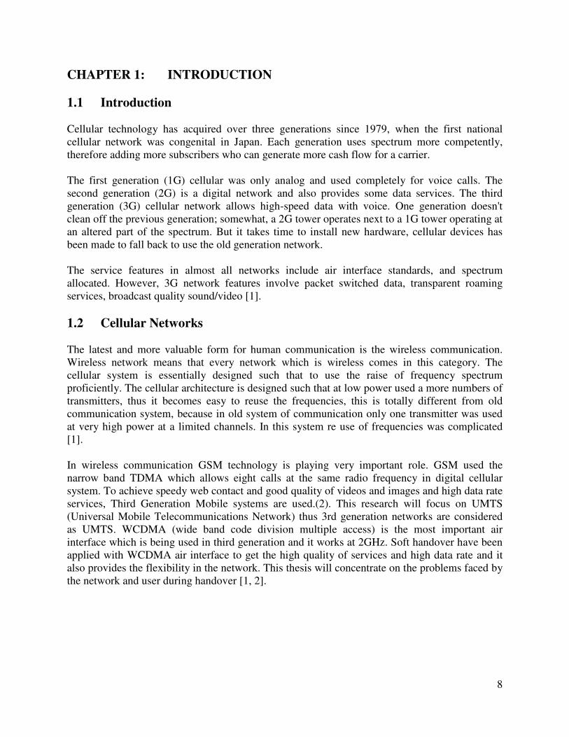
Cellular technology has acquired over three generations since 1979, when the first national
cellular network was congenital in Japan. Each generation uses spectrum more competently,
therefore adding more subscribers who can generate more cash flow for a carrier.
The first generation (1G) cellular was only analog and used completely for voice calls. The
second generation (2G) is a digital network and also provides some data services. The third
generation (3G) cellular network allows high-speed data with voice. One generation doesn't
clean off the previous generation; somewhat, a 2G tower operates next to a 1G tower operating at
an altered part of the spectrum. But it takes time to install new hardware, cellular devices has
been made to fall back to use the old generation network.
The service features in almost all networks include air interface standards, and spectrum
allocated. However, 3G network features involve packet switched data, transparent roaming
services, broadcast quality sound/video [1].
1.2 Cellular Networks
The latest and more valuable form for human communication is the wireless communication.
Wireless network means that every network which is wireless comes in this category. The
cellular system is essentially designed such that to use the raise of frequency spectrum
proficiently. The cellular architecture is designed such that at low power used a more numbers of
transmitters, thus it becomes easy to reuse the frequencies, this is totally different from old
communication system, because in old system of communication only one transmitter was used
at very high power at a limited channels. In this system re use of frequencies was complicated
[1].
In wireless communication GSM technology is playing very important role. GSM used the
narrow band TDMA which allows eight calls at the same radio frequency in digital cellular
system. To achieve speedy web contact and good quality of videos and images and high data rate
services, Third Generation Mobile systems are used.(2). This research will focus on UMTS
(Universal Mobile Telecommunications Network) thus 3rd generation networks are considered
as UMTS. WCDMA (wide band code division multiple access) is the most important air
interface which is being used in third generation and it works at 2GHz. Soft handover have been
applied with WCDMA air interface to get the high quality of services and high data rate and it
also provides the flexibility in the network. This thesis will concentrate on the problems faced by
the network and user during handover [1, 2].
9
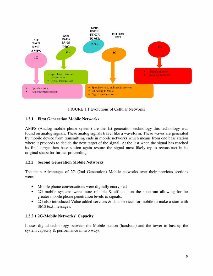
FIGURE 1.1 Evolutions of Cellular Networks
1.2.1 First Generation Mobile Networks
AMPS (Analog mobile phone system) are the 1st generation technology this technology was
found on analog signals. These analog signals travel like a waveform. These waves are generated
by mobile device from transmitting ends in mobile networks which means from one base station
where it proceeds to decide the next target of the signal. At the last when the signal has reached
its final target then base station again restore the signal most likely try to reconstruct in its
original shape for further proceeding.
1.2.2 Second Generation Mobile Networks
The main Advantages of 2G (2nd Generation) Mobile networks over their previous sections
were:
• Mobile phone conversations were digitally encrypted
• 2G mobile systems were more reliable & efficient on the spectrum allowing for far
greater mobile phone penetration levels & signals.
• 2G also introduced Value added services & data services for mobile to make a start with
SMS text messages.
1.2.2.1 2G-Mobile Networks’ Capacity
It uses digital technology between the Mobile station (handsets) and the tower to bust-up the
system capacity & performance in two ways:
• Speech service
• Analogue transmission
• Speech and low rate
data services
• Digital transmission
• Speech service, multimedia services
• Bit rate up to Mbit/s
• Digital transmission
1G
2G 3G
2.5G 4G
• Higher bit rate?
• New application?
NIT TACS NMT
AMPS
GSM IS-136 IS-95 PDC
GPRS HSCSD EDGE IS-95B
IMT-2000 UMT
10
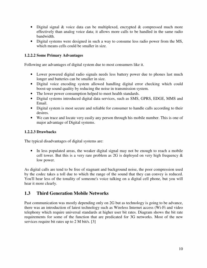
• Digital signal & voice data can be multiplexed, encrypted & compressed much more
effectively than analog voice data; it allows more calls to be handled in the same radio
bandwidth.
• Digital systems were designed in such a way to consume less radio power from the MS,
which means cells could be smaller in size.
1.2.2.2 Some Primary Advantages
Following are advantages of digital system due to most consumers like it.
• Lower powered digital radio signals needs less battery power due to phones last much
longer and batteries can be smaller in size.
• Digital voice encoding system allowed handling digital error checking which could
boost-up sound quality by reducing the noise in transmission system.
• The lower power consumption helped to meet health standards.
• Digital systems introduced digital data services, such as SMS, GPRS, EDGE, MMS and
Email.
• Digital system is most secure and reliable for consumer to handle calls according to their
desires.
• We can trace and locate very easily any person through his mobile number. This is one of
major advantage of Digital systems.
1.2.2.3 Drawbacks
The typical disadvantages of digital systems are:
• In less populated areas, the weaker digital signal may not be enough to reach a mobile
cell tower. But this is a very rare problem as 2G is deployed on very high frequency &
low power.
As digital calls are tend to be free of stagnant and background noise, the poor compression used
by the codec takes a toll due to which the range of the sound that they can convey is reduced.
You'll hear less of the tonality of someone's voice talking on a digital cell phone, but you will
hear it more clearly.
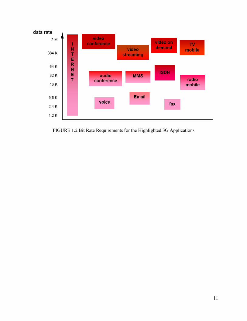
1.3 Third Generation Mobile Networks
Past communication was mostly depending only on 2G but as technology is going to be advance,
there was an introduction of latest technology such as Wireless Internet access (Wi-Fi and video
telephony which require universal standards at higher user bit rates. Diagram shows the bit rate
requirements for some of the function that are predicated for 3G networks. Most of the new
services require bit rates up to 2 M bit/s. [3]
11
FIGURE 1.2 Bit Rate Requirements for the Highlighted 3G Applications
12
CHAPTER 2: UMTS ARCHITECTURE AND FUNCTIONALITY
2.1 CDMA Technology
CDMA protocol is widely used in UMTS system. CDMA (Code Division Multiple Access) is
the higher speed transmission protocol. CDMA technology is the type of 3G cellular network.
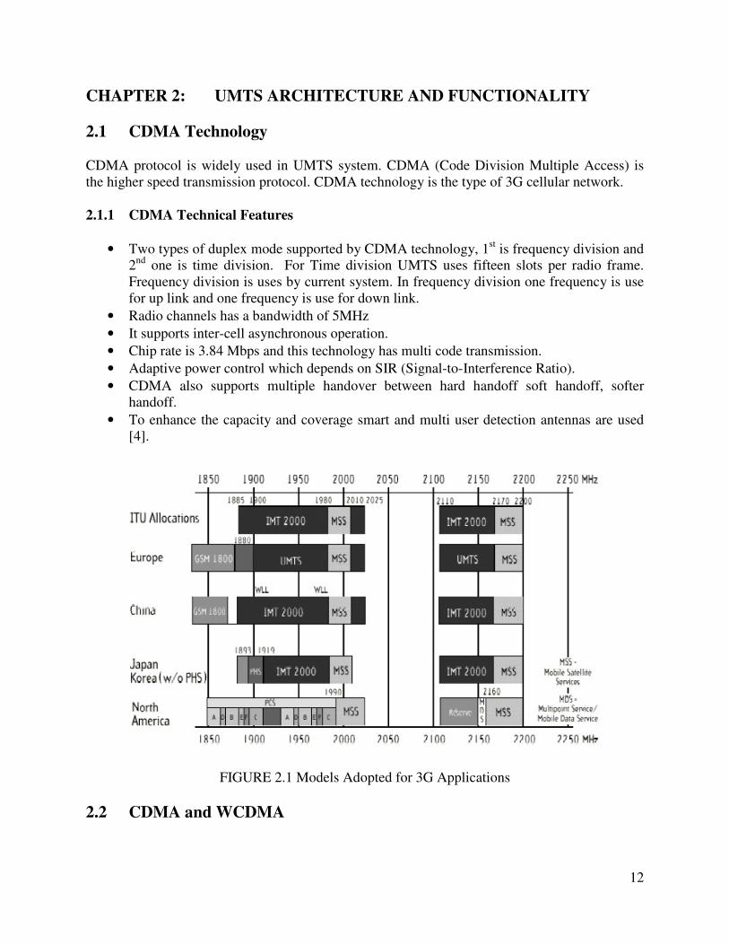
2.1.1 CDMA Technical Features
• Two types of duplex mode supported by CDMA technology, 1st is frequency division and
2nd
one is time division. For Time division UMTS uses fifteen slots per radio frame.
Frequency division is uses by current system. In frequency division one frequency is use
for up link and one frequency is use for down link.
• Radio channels has a bandwidth of 5MHz
• It supports inter-cell asynchronous operation.
• Chip rate is 3.84 Mbps and this technology has multi code transmission.
• Adaptive power control which depends on SIR (Signal-to-Interference Ratio).
• CDMA also supports multiple handover between hard handoff soft handoff, softer
handoff.
• To enhance the capacity and coverage smart and multi user detection antennas are used
[4].
FIGURE 2.1 Models Adopted for 3G Applications
2.2 CDMA and WCDMA
13
Users are separated by single codes in Code Division Multiple Access Technology, its mean that
all users can use the same frequency and for transmission as well. With the latest progress in
signal processing for wireless communication it is very suitable to use the technology that is also
referred as WCDMA. Wide radio signal of 5MHz in WCDMA is multiplied by pseudo-noise
code sequence (Spreading signal) with a higher rate than the data rate of the message. If the
proposed recipient has the right code then resulting signal appears as apparently random. The
original signal is extracted in the reverse of this process. Same frequency is repeated in all cells
by using unique codes, which is commonly known as a frequency re-use of 1. WCDMA chip rate
is 3.84 Mcps.
The advantages of a wideband carrier with a higher chip rate are:
• Support for higher bit rates
• Higher spectrum efficiency credit to better trunking efficiency means that statistical
averaging will be better.
• Higher QoS (Quality of Service) corresponds. [5].
Furthermore, from experience of second-generation systems like GSM has enabled
improvements to be included in WCDMA. The main focus has been put on WCDMA operators
investments for ensuring more possibilities of the reuse of GSM equipment. Re-use and
evolution of the core network and the focus on co-sitting and the support of GSM handover are
the examples. The subscribers need dual mode handset for the use of GSM handover.
2.3 Features of WCDMA
UMTS uses WCDMA technology due to its terrestrial radio access (UTRA). Here characteristics
of WCDMA which differs from GSM are described.
• WCDMA is wide band CDMA system with 5 MHz frequency band width using
spreading codes and decoding at the receiver end.[6]
• The Chip rate of 3.84 Mcps is used up to 5 MHz band width where as in GSM it is only
200 KHz. Therefore wide carrier band width of WCDMA supports high data rate.
• FDD (Frequency Division Duplex) and TDD (Time Division Duplex) are used in
WCDMA for uplink and downlink.
• WCDMA uses Asynchronous Mode for base station instead of synchronous mode as in
GSM
• The coherent uplink and downlink detection based on pilot symbol is employed in
WCDMA
• The WCDMA air interface is designed according to advanced CDMA concepts e.g.
multiuser detection ,network capacity increase option , smart adaptive antenna
coverage.[7]
• WCDMA is designed for GSM and WCDMA hand over support.
2.4 UMTS Complete Architecture and System Overview
14
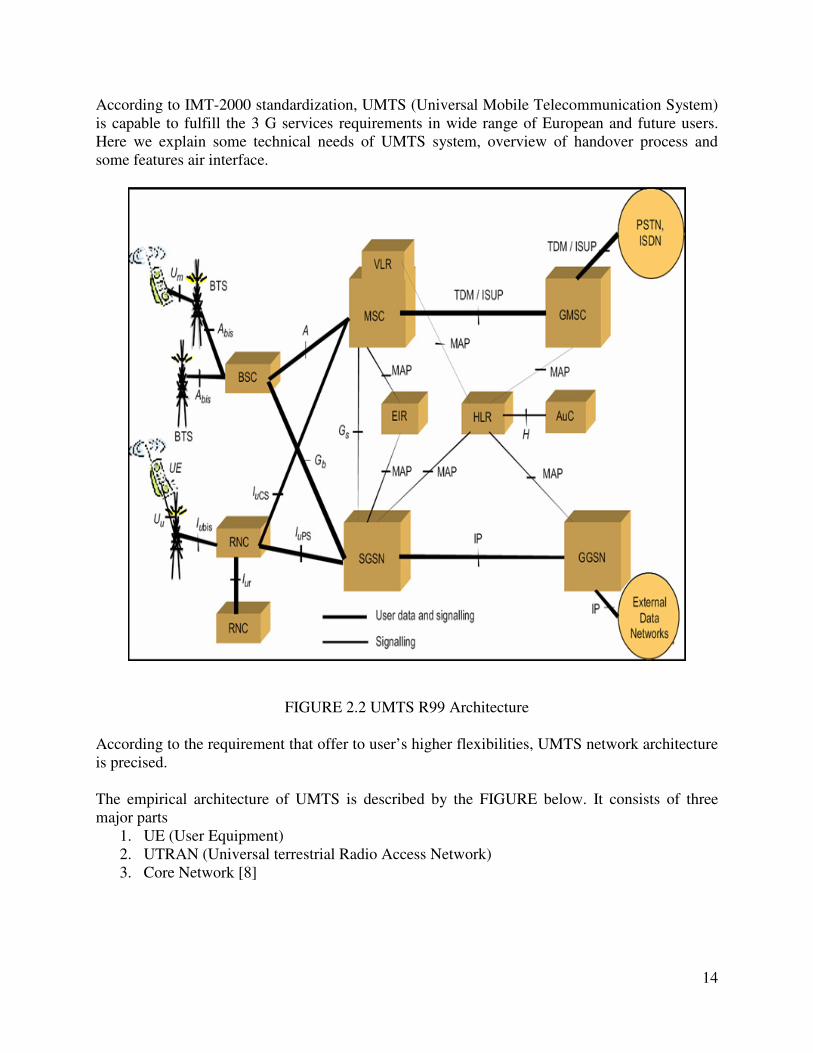
According to IMT-2000 standardization, UMTS (Universal Mobile Telecommunication System)
is capable to fulfill the 3 G services requirements in wide range of European and future users.
Here we explain some technical needs of UMTS system, overview of handover process and
some features air interface.
FIGURE 2.2 UMTS R99 Architecture
According to the requirement that offer to user’s higher flexibilities, UMTS network architecture
is precised.
The empirical architecture of UMTS is described by the FIGURE below. It consists of three
major parts
1. UE (User Equipment)
2. UTRAN (Universal terrestrial Radio Access Network)
3. Core Network [8]
15
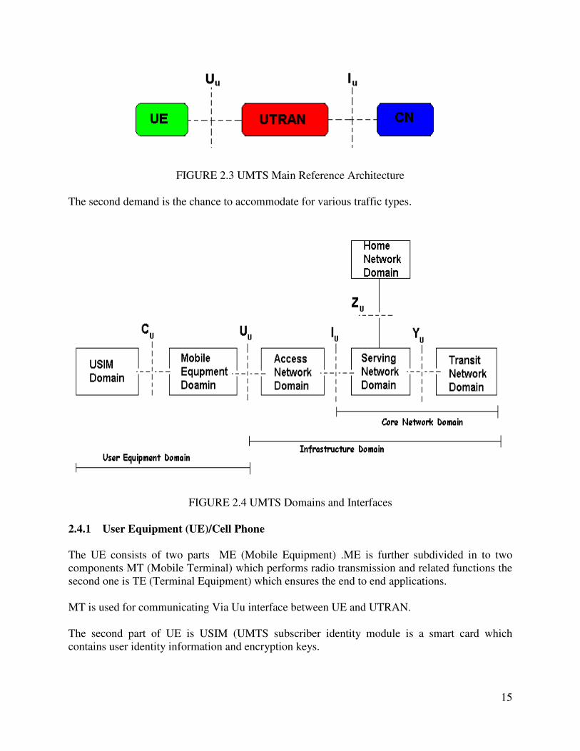
FIGURE 2.3 UMTS Main Reference Architecture
The second demand is the chance to accommodate for various traffic types.
FIGURE 2.4 UMTS Domains and Interfaces
2.4.1 User Equipment (UE)/Cell Phone
The UE consists of two parts ME (Mobile Equipment) .ME is further subdivided in to two
components MT (Mobile Terminal) which performs radio transmission and related functions the
second one is TE (Terminal Equipment) which ensures the end to end applications.
MT is used for communicating Via Uu interface between UE and UTRAN.
The second part of UE is USIM (UMTS subscriber identity module is a smart card which
contains user identity information and encryption keys.
16
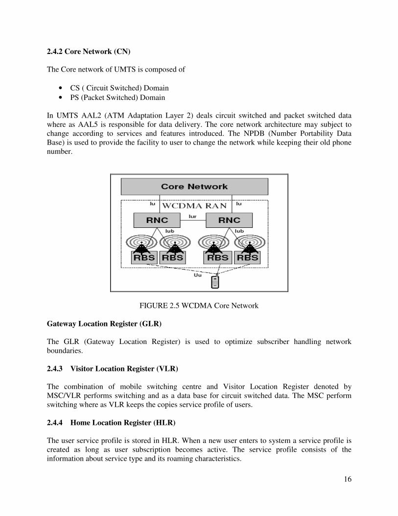
2.4.2 Core Network (CN)
The Core network of UMTS is composed of
• CS ( Circuit Switched) Domain
• PS (Packet Switched) Domain
In UMTS AAL2 (ATM Adaptation Layer 2) deals circuit switched and packet switched data
where as AAL5 is responsible for data delivery. The core network architecture may subject to
change according to services and features introduced. The NPDB (Number Portability Data
Base) is used to provide the facility to user to change the network while keeping their old phone
number.
FIGURE 2.5 WCDMA Core Network
Gateway Location Register (GLR)
The GLR (Gateway Location Register) is used to optimize subscriber handling network
boundaries.
2.4.3 Visitor Location Register (VLR)
The combination of mobile switching centre and Visitor Location Register denoted by
MSC/VLR performs switching and as a data base for circuit switched data. The MSC perform
switching where as VLR keeps the copies service profile of users.
2.4.4 Home Location Register (HLR)
The user service profile is stored in HLR. When a new user enters to system a service profile is
created as long as user subscription becomes active. The service profile consists of the
information about service type and its roaming characteristics.
17
2.4.5 Mobile Switching Center and Visitor Location Register (MSC/VLR)
The combination of mobile switching centre and Visitor Location Register denoted by
MSC/VLR performs switching and as a data base for circuit switched data. The MSC perform
switching where as VLR keeps the copies service profile of users.
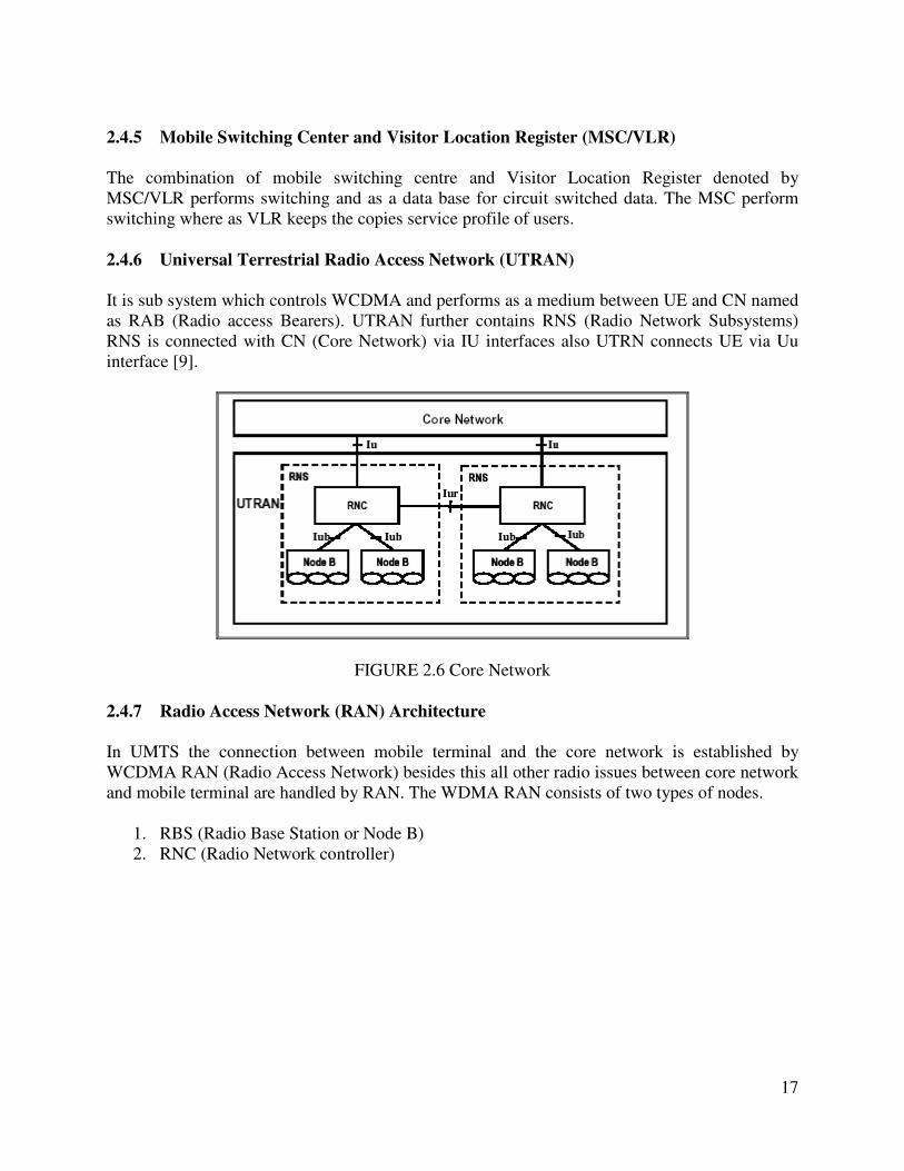
2.4.6 Universal Terrestrial Radio Access Network (UTRAN)
It is sub system which controls WCDMA and performs as a medium between UE and CN named
as RAB (Radio access Bearers). UTRAN further contains RNS (Radio Network Subsystems)
RNS is connected with CN (Core Network) via IU interfaces also UTRN connects UE via Uu
interface [9].
FIGURE 2.6 Core Network
2.4.7 Radio Access Network (RAN) Architecture
In UMTS the connection between mobile terminal and the core network is established by
WCDMA RAN (Radio Access Network) besides this all other radio issues between core network
and mobile terminal are handled by RAN. The WDMA RAN consists of two types of nodes.
1. RBS (Radio Base Station or Node B)
2. RNC (Radio Network controller)

18
FIGURE 2.7 WCDMA Radio Access Network
Radio Base Station (Node B)
In UMTS radio transmission and reception to mobile terminal, from mobile terminal via radio
interface is done by RBS. The RNC Radio Network Controller manages RBC via Iub interface.
One or more UMTS cells are covered RBS.
Radio Network Controller (RNC)
All WCDMA radio access and network functions are handled by RAN. RAN is also responsible
for the connection between WCDMA and core network using IU interface RNC performs two
different roles to serve and to control in serving RNC manages overall issues of handset or
mobile terminal with WCDMA including connection and termination of protocols.
In controlling RNC it manages the overall control of a specific cell and their associations. When
a mobile terminal uses the resources of a cell which is not controlled by RNC then serving RNC
enquire controlling RNC about these resources. The request is send via IU interface. In this case
controlling RNC is also called Drift RNC. This process is done in case of soft handover.
2.4.7.1 Radio Network Functionality
For optimal operation of a wireless system i.e. from handset to radio access network (RAN)
numerous functions are needed to control the radio network and many handsets are using it.
Except for Handover to GSM, all functions are described in this section are important and
necessary for a WCDMA system.
.

19
2.4.7.2 Radio Access Technique in UMTS (W-CDMA)
W-CDMA is a radio access method in 3G UMTS networks. TDMA used in 2G networks while
W-CDMA in 3G. WCDMA has main advantages over TDMA like higher system capacity and
more stretchy use
FIGURE 2.8 Frequency Reuse Comparisons between GSM & WCDMA
of the narrow radio spectrum. From the previous approaches and from simplistic point of view
the available bandwidth in a cell depended not only on the total allocated bandwidth of the
spectrum, but also on the frequency re-use pattern. For example, if a re-use pattern of 7 cells was
used, the bandwidth available in each cell is one seventh of the total as illustrated in the
FIGURE. The whole bandwidth can be reused in each cell for UMTS as W-CDMA technique is
in work.
The use of spread spectrum provides sharing of the resource in W-CDMA. Each user uses spread
spectrum modulation and the message signal is spread over a wide band after multiplication it
with a pseudo-random spreading signal. In demodulation, the signal at receiver is cross-
connected with an exact duplication of the spreading function in order to differentiate itself from
other users and noise.
20
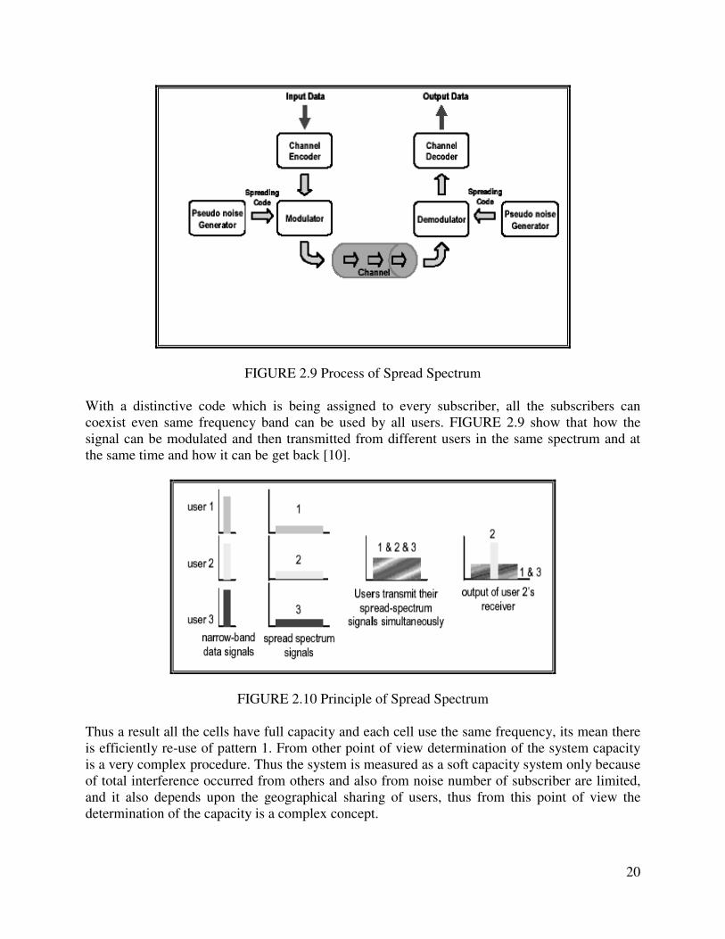
FIGURE 2.9 Process of Spread Spectrum
With a distinctive code which is being assigned to every subscriber, all the subscribers can
coexist even same frequency band can be used by all users. FIGURE 2.9 show that how the
signal can be modulated and then transmitted from different users in the same spectrum and at
the same time and how it can be get back [10].
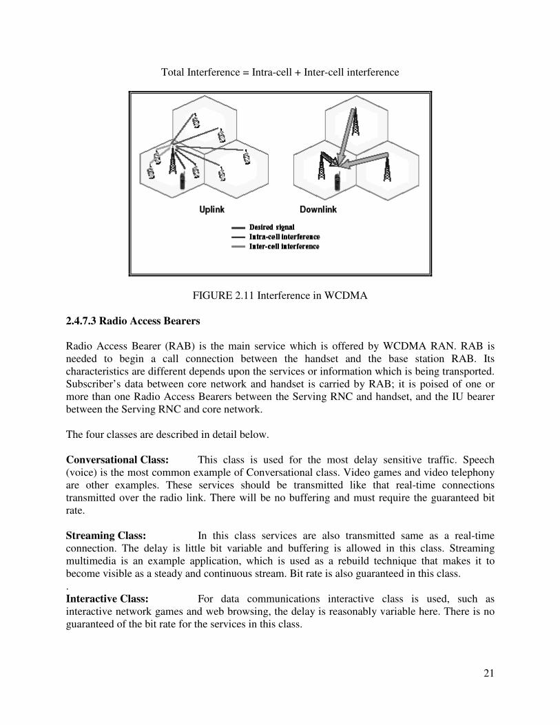
FIGURE 2.10 Principle of Spread Spectrum
Thus a result all the cells have full capacity and each cell use the same frequency, its mean there
is efficiently re-use of pattern 1. From other point of view determination of the system capacity
is a very complex procedure. Thus the system is measured as a soft capacity system only because
of total interference occurred from others and also from noise number of subscriber are limited,
and it also depends upon the geographical sharing of users, thus from this point of view the
determination of the capacity is a complex concept.
21
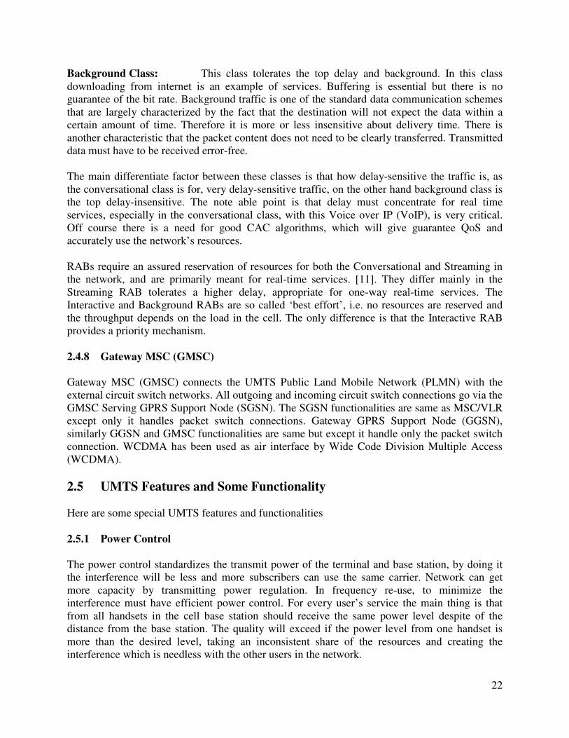
Total Interference = Intra-cell + Inter-cell interference
FIGURE 2.11 Interference in WCDMA
2.4.7.3 Radio Access Bearers
Radio Access Bearer (RAB) is the main service which is offered by WCDMA RAN. RAB is
needed to begin a call connection between the handset and the base station RAB. Its
characteristics are different depends upon the services or information which is being transported.
Subscriber’s data between core network and handset is carried by RAB; it is poised of one or
more than one Radio Access Bearers between the Serving RNC and handset, and the IU bearer
between the Serving RNC and core network.
The four classes are described in detail below.
Conversational Class: This class is used for the most delay sensitive traffic. Speech
(voice) is the most common example of Conversational class. Video games and video telephony
are other examples. These services should be transmitted like that real-time connections
transmitted over the radio link. There will be no buffering and must require the guaranteed bit
rate.
Streaming Class: In this class services are also transmitted same as a real-time
connection. The delay is little bit variable and buffering is allowed in this class. Streaming
multimedia is an example application, which is used as a rebuild technique that makes it to
become visible as a steady and continuous stream. Bit rate is also guaranteed in this class.
.
Interactive Class: For data communications interactive class is used, such as
interactive network games and web browsing, the delay is reasonably variable here. There is no
guaranteed of the bit rate for the services in this class.
22
Background Class: This class tolerates the top delay and background. In this class
downloading from internet is an example of services. Buffering is essential but there is no
guarantee of the bit rate. Background traffic is one of the standard data communication schemes
that are largely characterized by the fact that the destination will not expect the data within a
certain amount of time. Therefore it is more or less insensitive about delivery time. There is
another characteristic that the packet content does not need to be clearly transferred. Transmitted
data must have to be received error-free.
The main differentiate factor between these classes is that how delay-sensitive the traffic is, as
the conversational class is for, very delay-sensitive traffic, on the other hand background class is
the top delay-insensitive. The note able point is that delay must concentrate for real time
services, especially in the conversational class, with this Voice over IP (VoIP), is very critical.
Off course there is a need for good CAC algorithms, which will give guarantee QoS and
accurately use the network’s resources.
RABs require an assured reservation of resources for both the Conversational and Streaming in
the network, and are primarily meant for real-time services. [11]. They differ mainly in the
Streaming RAB tolerates a higher delay, appropriate for one-way real-time services. The
Interactive and Background RABs are so called ‘best effort’, i.e. no resources are reserved and
the throughput depends on the load in the cell. The only difference is that the Interactive RAB
provides a priority mechanism.
2.4.8 Gateway MSC (GMSC)
Gateway MSC (GMSC) connects the UMTS Public Land Mobile Network (PLMN) with the
external circuit switch networks. All outgoing and incoming circuit switch connections go via the
GMSC Serving GPRS Support Node (SGSN). The SGSN functionalities are same as MSC/VLR
except only it handles packet switch connections. Gateway GPRS Support Node (GGSN),
similarly GGSN and GMSC functionalities are same but except it handle only the packet switch
connection. WCDMA has been used as air interface by Wide Code Division Multiple Access
(WCDMA).
2.5 UMTS Features and Some Functionality
Here are some special UMTS features and functionalities
2.5.1 Power Control
The power control standardizes the transmit power of the terminal and base station, by doing it
the interference will be less and more subscribers can use the same carrier. Network can get
more capacity by transmitting power regulation. In frequency re-use, to minimize the
interference must have efficient power control. For every user’s service the main thing is that
from all handsets in the cell base station should receive the same power level despite of the
distance from the base station. The quality will exceed if the power level from one handset is
more than the desired level, taking an inconsistent share of the resources and creating the
interference which is needless with the other users in the network.

23
In contrast, if the power levels are very low then the result will be in poor quality. On the other
hand to keep the received power at a suitable level, WCDMA has a very fast power control
which updates the power levels 1500 times each second. Then the rapidly change is handled in
the radio station to make sure high performance, the power control is implemented for up-link
and the downlink as well, means that base station and output handset powers are updated
regularly.
2.5.2 Cell Breathing
Cell breathing phenomenon gets higher from power control. The cell size varies because it
depends upon the traffic load. This is the exchange between coverage and capacity. Good quality
can be gained though from a long distance from base station when there is low load in the cell
means number of users will be less in the cell. On the other hand, when the number of users in
the cell is high, the large number of subscribers generates a high interference level and
subscribers have to get closer to the base station to achieve good quality. If the number of users
is higher in the cell then to get the good quality the users should get closer to the base station and
in case of more users, far away from base station there will involve more interference.
FIGURE 2.12 Call Bearing Examples
2.5.3 Channel Type Switching
In order to maximize the total traffic throughput, different types of channels are used to transmit
the data in WCDMA. To move the subscribers between the two channels like between common
channels and dedicated channels, depending upon the information that subscribers need to
transmit, Channel type switching functionality will be used.
The two most basic ones are: Dedicated Channels: When there is enough information for transmission, for example
downloading, voice conversation then dedicated channel is used. Its efficiently utilizes the radio
resources because it provide supports for power control and soft handover.

24
Common Channels: The common channel, in contrast, is smaller quantity spectrums
efficient. As many subscribers can share the same resource, the common channel reduces the
delays. This is one of the advantages of common channel. Thus for the transfer of limited
information common channel is a preferable channel.
Admission Control: To avoid system overload and for providing planned coverage,
Admission control functionality is used. This functionality is used because in WCDMA there is
very clear exchange between coverage and capacity. When a new subscriber looks access to the
network, the admission control functionality estimates the network load on the base of newly
coming load, then subscriber is either allowed to enter in the network or being blocked.
According to the services of subscriber’s demand the operator can expand the network usage
with in a set of network quality levels.
2.5.4 Congestion Control
Overload may also occur even in case of using efficient admission control. The main cause of
this is due to the movement of subscribers from one area to another one. In case of overload four
different actions can be taken.
• To resolve the overload issue congestion control becomes activated and its decreases the
bit rate of non real time applications.
• If overload issue is not fully solved by reducing bit rate then inter or intra frequency
handover becomes active by congestion control, which moves some of the subscribers to
the less loaded frequencies.
• Some subscribers are being handover to GSM
• Finally, The action of discontinue is taken to keep the quality of the remaining
connections.
2.5.5 Synchronization
For accurate synchronization of base stations, when WCDMA system was standardized, should
not depend on external systems and this is the basic requirement for synchronization. This has
achieved by a method, where the handset, when needed, measures the synchronization of offset
between the different cells and then reports this to the network [12].
Moreover, there is also another option for the use of an external source, for example GPS, for
node synchronization, i.e. to always give the top solution for both asynchronous and synchronous
nodes are supported.
In 3G network different UTRAN synchronization are required:
• Node synchronization
• Network synchronization
• Transport channel synchronization
• Time alignment handling
• Radio interface synchronization

25
FIGURE 2.13 Synchronization Issues Model
2.5.5.1 Network Synchronization
It relates to the sharing of the references of synchronization to the UTRAN Nodes and the
strength of the clocks in the UTRAN (and performance necessities on UTRAN internal
interfaces). The distribution of an exact frequency reference to the elements of network in the
UTRAN is related to many aspects. In order to generate accurate signals on the radio interface
one main thing is the possibility to give a synchronization reference with frequency accuracy
better than 0.05 ppm at the Node B [13].
2.5.5.2 Node Synchronization
Node Synchronization relates to the assessment and reward of timing differences among
UTRAN nodes. FDD and TDD modes have different requirements on the accuracy of the timing
difference judgment and on the necessity to pay compensation for these differences. At Node
synchronization positioning or localization functions may also set the requirements.
2.5.5.3 The Transport Channel Synchronization
This mechanism explains synchronization of frame transport between RNC and Node B,
considering the timing of radio interfaces [14].
2.5.5.4 The Radio Interface Synchronization
Refers to the date of transmission of Radio framework (equivalent to a downlink (FDD) or in
both directions [TDD, FDD and TDD various mechanisms for determining the date of the
26
structure of the radio communications and various requirements of the accuracy of this timetable.
Radio interface in FDD synchronization is necessary to ensure that the UE as flash Radio
different cells, to minimize UE buffers.
2.5.6 Time Alignment Handling
In order to reduce the buffer stoppage in SNRC, the procedure over IU relates to the control
transmission timing of DL in the CN nodes. SRNC controlled this procedure [15].
27
CHAPTER 3: UMTS HANDOVER
3.1 What is Handover?
During the last thirteen years the Internet and 2nd Generation wireless telecommunications
systems like GSM (Global System Mobile) have spread themselves very fast over the free
market countries. But now due to low data rate of second generation telecommunications
systems there is a need of high data rate so one can enjoy the multimedia services like quality
video streaming and high speed internet on his mobile phone so the third generation mobile
systems are needed to replace the old telecommunication systems. Here in this report the UMTS
(Universal Mobile Telecommunications System) taken as the 3rd generation networks and the
most common form of UMTS as air interface is the WCDMA (Wideband Code Division
Multiple Access). In order to get the high quality of service with faultless communication in our
networks soft handovers are implemented in the networks. Handover is a process when a user
switches to another channel without any interruption and when we talk about 3rd generation
networks we use soft handover because in soft handover mobile phone connects to another
channel before leaving first channel and that is why soft handover is also known as Make-
Before-Brake. We are going to confer in detail soft handovers in the UMTS and observe the
effect of these handovers on the performance of the system [16].
3.2 Types of Handovers
Typically there are many types of handovers in WCDMA mobile networks. These are explained
below:
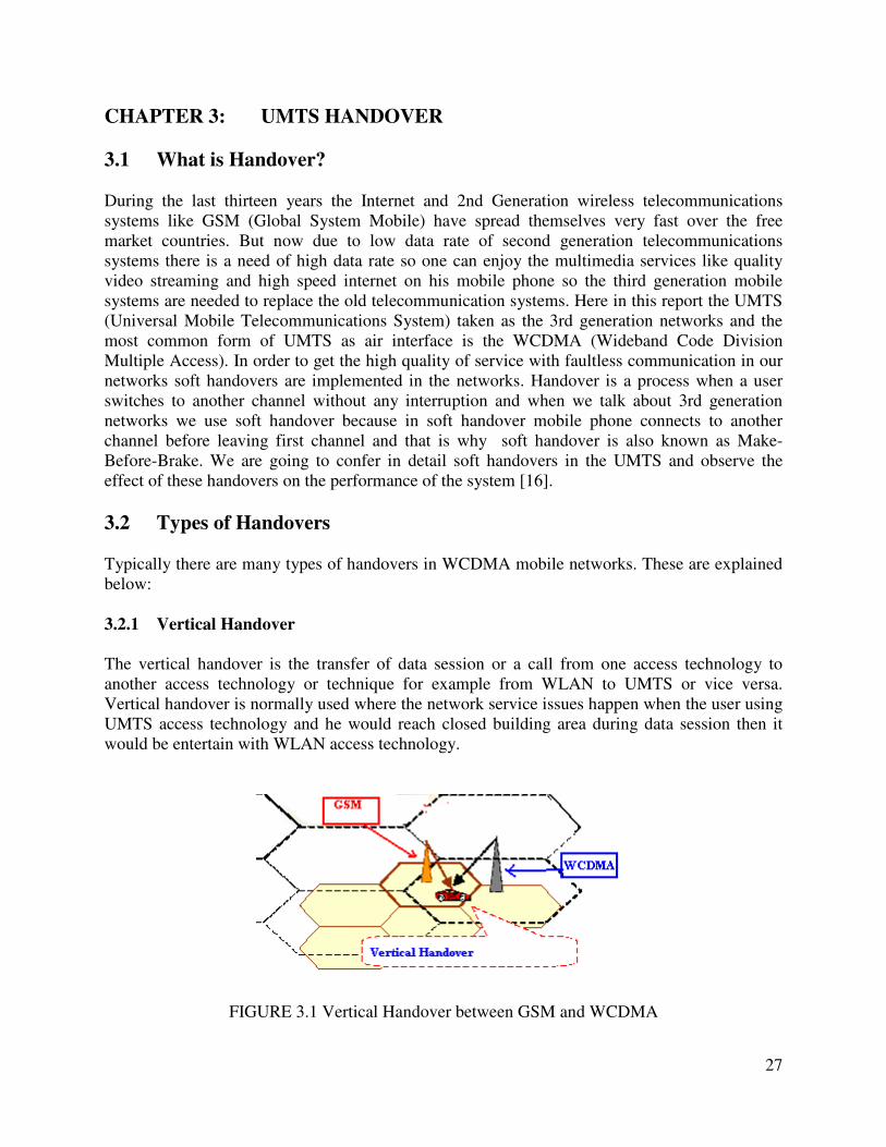
3.2.1 Vertical Handover
The vertical handover is the transfer of data session or a call from one access technology to
another access technology or technique for example from WLAN to UMTS or vice versa.
Vertical handover is normally used where the network service issues happen when the user using
UMTS access technology and he would reach closed building area during data session then it
would be entertain with WLAN access technology.
FIGURE 3.1 Vertical Handover between GSM and WCDMA
28
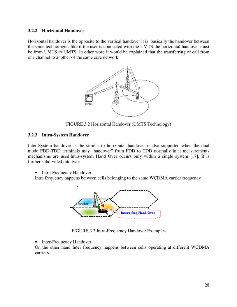
3.2.2 Horizontal Handover
Horizontal handover is the opposite to the vertical handover it is basically the handover between
the same technologies like if the user is connected with the UMTS the horizontal handover must
be from UMTS to UMTS. In other word it would be explained that the transferring of call from
one channel to another of the same core network.
FIGURE 3.2 Horizontal Handover (UMTS Technology)
3.2.3 Intra-System Handover
Inter-System handover is the similar to horizontal handover it also supported when the dual
mode FDD-TDD terminals may “handover” from FDD to TDD normally in it measurements
mechanisms are used.Intra-system Hand Over occurs only within a single system [17]. It is
further subdivided into two:
• Intra-Frequency Handover
Intra frequency happens between cells belonging to the same WCDMA carrier frequency
FIGURE 3.3 Intra-Frequency Handover Examples
• Inter-Frequency Handover
On the other hand Inter frequency happens between cells operating at different WCDMA
carriers.
29
FIGURE 3.4 Inter-Frequency Handover Example
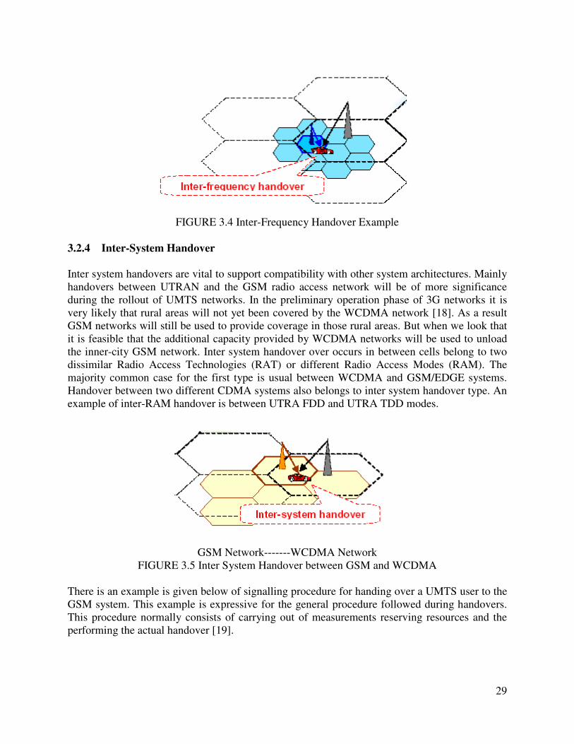
3.2.4 Inter-System Handover
Inter system handovers are vital to support compatibility with other system architectures. Mainly
handovers between UTRAN and the GSM radio access network will be of more significance
during the rollout of UMTS networks. In the preliminary operation phase of 3G networks it is
very likely that rural areas will not yet been covered by the WCDMA network [18]. As a result
GSM networks will still be used to provide coverage in those rural areas. But when we look that
it is feasible that the additional capacity provided by WCDMA networks will be used to unload
the inner-city GSM network. Inter system handover over occurs in between cells belong to two
dissimilar Radio Access Technologies (RAT) or different Radio Access Modes (RAM). The
majority common case for the first type is usual between WCDMA and GSM/EDGE systems.
Handover between two different CDMA systems also belongs to inter system handover type. An
example of inter-RAM handover is between UTRA FDD and UTRA TDD modes.
GSM Network-------WCDMA Network
FIGURE 3.5 Inter System Handover between GSM and WCDMA
There is an example is given below of signalling procedure for handing over a UMTS user to the
GSM system. This example is expressive for the general procedure followed during handovers.
This procedure normally consists of carrying out of measurements reserving resources and the
performing the actual handover [19].

30
FIGURE 3.6 Inter-System Handover Procedure from UTRAN to GSM
While switching the connection to another system architecture there is need for an extent on the
frequency used by the other system. When there is no full dual receiver available the
transmission and reception are halted for a while to perform measurements on the other
frequencies [20]. This is said to be a compressed mode.
3.2.5 Hard Handover
In Hard handover all the old radio links in the UE are removed before the new radio links are
connected. Hard handover could be seamless or non-seamless. Seamless hard handover means
that the handover is not effectible to the user. Normally a handover that requires a change of the
carrier frequency (inter-frequency handover) is always similar as hard handover. From real-time
bearer it means a short disconnection of the bearer and for non-real-time bearers hard handover
is lossless. Hard handover can take place as intra or inter-frequency handover.
Hard handover is also called the conventional handover it has some advantages like the user can
not hold more than one channel at all time and mobile doesn’t need complex hard where to
receive two channel at the same time. Hard handover is firstly introduced in GSS technology; On
the other hand hard handover has some disadvantage also like there are many chances of call
drop during hard handover which increase the call drop probability [21].
FIGURE 3.7 Hard Handover Examples

31
3.2.6 Soft Handover
Soft handover was actually introduced by CDMA technology. Compared to the conventional
hard handover it got few advantages. But in other hand it also has the some disadvantages. In
Soft handover the UE can be connected to more than one channels at the same time, it is also
know as make before break because it keep the previous channel from source until it gets the
channel from source cell. Although soft handover increase the complexities but it has many
advantages also like the high hand over success rate and reduction of call drop probability and
elimination of inference [22].
FIGURE 3.8 Soft Handover Examples
When the same BS receives two signals from a single user due to multipath this is called softer
handover it uses one carrier frequency so it is an intra-frequency handover.
FIGURE 3.9 Softer Handover Examples
3.3 Basic Principle of Soft Handover
The soft handover process is different in the different transmission directions. In the uplink
direction the mobile transmits the signals to the air through its Omni directional antenna. The
two BSs in the active set receive the signals at the same time due to the frequency reuse factor of
one in CDMA systems [23]. After that, the signals are sent forward to the RNC for selection
combining. The better frame is considered and the other is discarded. As a result, in the uplink
direction, there is no extra channel required to support soft handover process [24]. But In the
downlink, this not the case same signals are transmitted during both BSs and the mobile can
simply combine the signals from different BSs since it sees them as just additional multipath
components.

32
FIGURE 3.10 Soft Handover Scenarios
During soft handover, a mobile at the same time communicates with two (2-way soft Handover)
or more cells belonging to different BSs of the identical RNC (intra-RNC) or different RNCs
(inter-RNC).
Usually maximum ratio combining scheme is used, which provides an additional benefit called
macro diversity. Due to which to support soft handover in the downlink direction, at least one
extra downlink channel (2-way soft handover) is required. This extra downlink channel acts to
other users acts as an additional interference in the air interface. Therefore, to support soft
handover in the downlink, more resource is essential. As a result, in the downlink direction, the
performance of the soft handover depends on the exchange between the macro diversity gain and
the extra resource consumption [25].
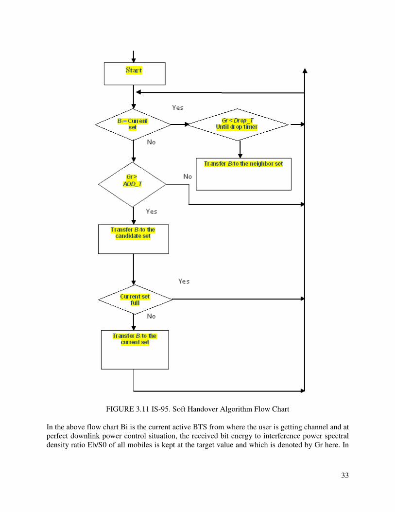
3.4 Soft Handover Algorithm
A method and a gadget to provide a smooth algorithm improved of the handoff in a system of
communication without threads for the multiple systems of the access of the division of the code
of the third generation (CDMA). The method covers to establish the communication among the
device without threads and at least at a low station that serves. The proper soft hand over
algorithm can increase the system performance now here two conventional soft handover
algorithms are shown below in the form of flow chart [26].
33
FIGURE 3.11 IS-95. Soft Handover Algorithm Flow Chart
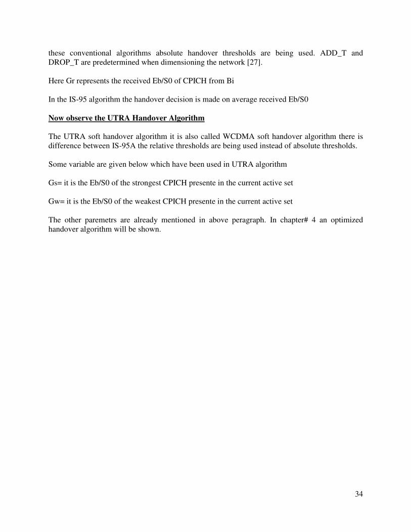
In the above flow chart Bi is the current active BTS from where the user is getting channel and at
perfect downlink power control situation, the received bit energy to interference power spectral
density ratio Eb/S0 of all mobiles is kept at the target value and which is denoted by Gr here. In
34
these conventional algorithms absolute handover thresholds are being used. ADD_T and
DROP_T are predetermined when dimensioning the network [27].
Here Gr represents the received Eb/S0 of CPICH from Bi
In the IS-95 algorithm the handover decision is made on average received Eb/S0
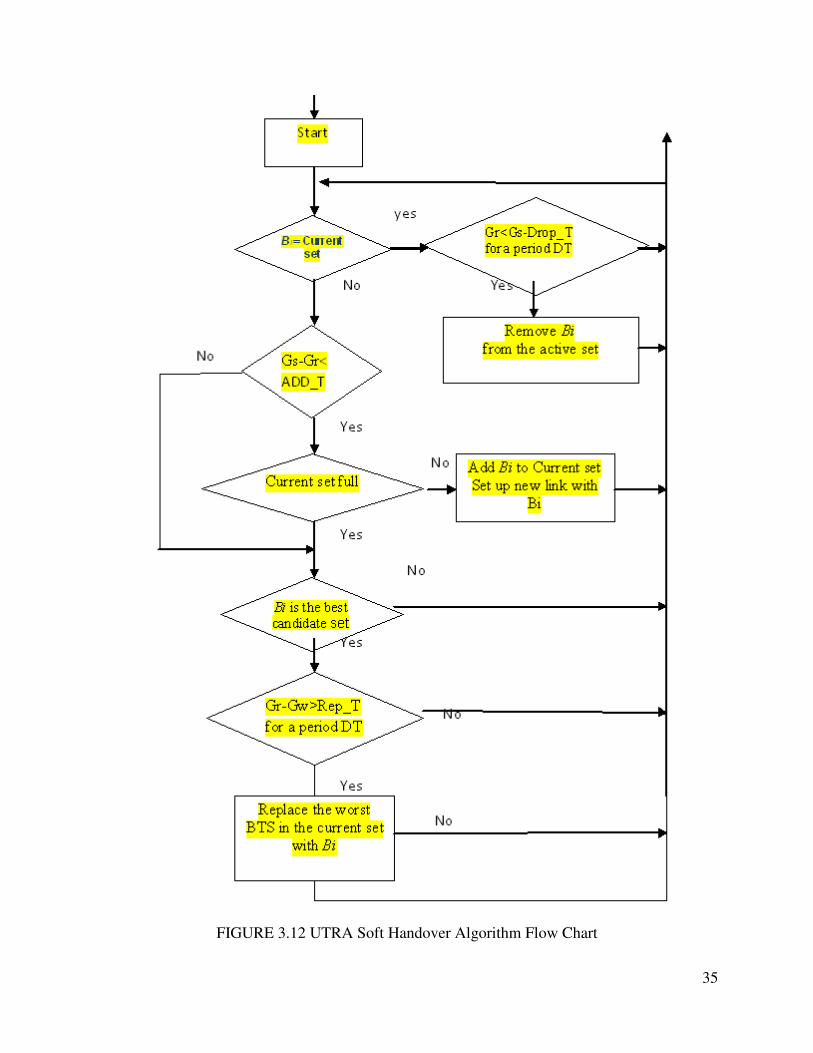
Now observe the UTRA Handover Algorithm
The UTRA soft handover algorithm it is also called WCDMA soft handover algorithm there is
difference between IS-95A the relative thresholds are being used instead of absolute thresholds.
Some variable are given below which have been used in UTRA algorithm
Gs= it is the Eb/S0 of the strongest CPICH presente in the current active set
Gw= it is the Eb/S0 of the weakest CPICH presente in the current active set
The other paremetrs are already mentioned in above peragraph. In chapter# 4 an optimized
handover algorithm will be shown.
35
FIGURE 3.12 UTRA Soft Handover Algorithm Flow Chart

36
3.5 Feature Related to Soft Handover
The Soft Handover has many advantages when comparing to traditional handover (Hard
handover etc). it improved the seamless communication and the main feature of the soft
handover is that there is no break in transmission that’s why it is called as a make before break
while in hard handover there is a break during hand over and therefore the chances of success of
handover becomes less that’s why it often called break before make. Another feature includes the
lower load on to the network and the soft handover process also eliminates the interference
which is also a big feature of WCDMA system due to soft handover this interference elimination
happens on uplink channel. There are many other features which are related to Soft handover like
better communication for users, greater capacity with maintaining the same Quality of service, it
gives a more time to get to the desired BS which directly effect the blocking probability and
reduce it and it also reduce the call dropping probability [28].
Although there are many advantages of soft handover and it contain pretty good feature there are
some disadvantages of soft handover as compared to traditional handover like it increase the
complexity and also consume extra resources in downlink direction.
FIGURE 3.13 Downlink Traffic Channels Maximal Ratio
37
CHAPTER 4: OPTIMIZATION STRATEGIES FOR SOFT HANDOVER
4.1 Introduction
The soft hand over performance is strongly based on to the algorithm and the soft handover
parameters. Hence it is very important to set proper algorithm and parameters of soft handover
should be set proper in order to get better handover performance.
4.2 New Strategies for Soft Handover
In this chapter we will discuss some new strategies to optimizing the soft handover issue and to
get the full benefits from soft handover.
4.2.1 Algorithms
The proper algorithm will really boost the soft handover performance. Now when talking about
soft handover algorithm there are two typical algorithms IS-95A and UTRAN algorithm. The IS-
95A soft handover algorithm can be optimize to reduce the system down time probability and
when we modify the threshold level in IS-95A algorithm according to the traffic then we can also
find good response and the high rate soft handover can also be avoid with some modification.
The threshold level must be set according to the acceleration of mobile users. The analysis of
comparison of using different algorithm can give us maximum capacity gain [29].
4.2.2 Downlink Capacity
In UMTS the another soft hand optimization can be done by increasing the downlink capacity
because the downlink capacity also effect the whole system capacity so in order to increase the
downlink capacity it needs to reduce the downlink interference.
4.2.3 Network Coverage
The network coverage and increasing the capacity also can optimize the soft handover process.
When capacity of the system will be increase which will automatically increase the soft handover
success rate and when we talk about the network coverage it will reduce the soft handover
occurrence hence it can be a good soft handover optimization strategy [30].
4.2.4 Soft Handover Parameters
Soft hand over parameters plays a big role in the optimization. The different parameters can be
used with using various combinations. And then the performance can be compared after
analyzing of different combination of soft handover parameters. Here the soft handover
parameters are like different threshold levels.
38
4.3 Optimized Power Control Scheme during Soft Handover
Now the power control schemes are anticipated for optimizing the power dissection between the
BSc in the active position during soft handover. Power control during soft handover, Describes
the principles of the proposed power control scheme. The feasibility of the new scheme is
evaluated. Afterwards, the system level performance of the new scheme is investigated under
UTRA soft handover algorithm by comparing to the balanced power control [31].
At some point in the power control method is more complex because there are at least two BSc
involved. In the uplink path, the mobile terminal adjusts it’s transmit power based on the
permutation of the received transmit power control (TPS) command from all BSc in the active
set. Consequently, the consistency of TPC bits and the proper combining approach are fatal to
the uplink power control during soft handover.
Downlink power control schemes through soft handover commonly assumed that is deviation in
the transmit powers form different power stations in the active set can lead to the reduction of the
macro diversity gain. A couple of technique have been planned to keep away from the power
drifting, the amendment loop power control was planned to sustain the balance of the transmit
power from different base station in the active set. As well as the inner closed loop power
control, an amendment loop is employed for balancing the downlink power among active set
cells through macro diversity. An unbalanced power allocation scheme was investigated that it
can decrease the overall transmit power. In this system, the BS has a better connect with the
mobile transmit signal at higher power. Site choice diversity transmits power control (STDT),
which has been adopting by 3GPP as a substitute plan for soft handover. The principle of SSDT
is that the best BS of the active set is dynamically selected as the only transmitting site, and other
BSc concerned turn down their DPDCHs (Dedicated Physical Control Channel). In this method,
the interference caused by the various site transmissions is mitigated. On the other hand, SSDT
loses the benefits of macro diversity. In this theory, an optimized downlink power control plan is
anticipated [32].
As mentioned and confirmed, CDMA systems are interference-limited. Reducing the total
nosiness is one of the basic conventions for optimizing the radio resource in CDMA system. The
basic rule of the new approach is to reduce the total power control approach is to reduce the total
power utilization during the soft handover as lower power utilization mean less nosiness to other
active users.
4.4 Theory of Soft Handover Optimization
As we know that the WCDMA systems are high capacity and interference limited systems and
downlink is affected by soft handover is much more complicated than the uplink affected by the
soft handover.
4.4.1 Extra Resource Management
In soft handover there is no extra channel is needed for uplink which definitely saves the extra
resources and hence the capacity is also increased. But this is not the case in downlink due to
39
extra channel the extra resources consumed by these channels which also increase the downlink
interference. So to optimize this soft handover process the downlink capacity must be increased
and from analysis it can be when the extra resources would be managed [33].
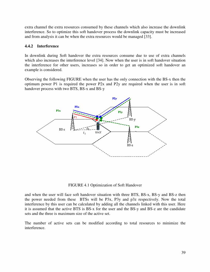
4.4.2 Interference
In downlink during Soft handover the extra resources consume due to use of extra channels
which also increases the interference level [34]. Now when the user is in soft handover situation
the interference for other users, increases so in order to get an optimized soft handover an
example is considered.
Observing the following FIGURE when the user has the only connection with the BS-x then the
optimum power P1 is required the power P2x and P2y are required when the user is in soft
handover process with two BTS, BS-x and BS-y
FIGURE 4.1 Optimization of Soft Handover
and when the user will face soft handover situation with three BTS, BS-x, BS-y and BS-z then
the power needed from these BTSs will be P3x, P3y and p3z respectively. Now the total
interference by this user can be calculated by adding all the channels linked with this user. Here
it is assumed that the active BTS is BS-x for the user and the BS-y and BS-z are the candidate
sets and the three is maximum size of the active set.
The number of active sets can be modified according to total resources to minimize the
interference.
40
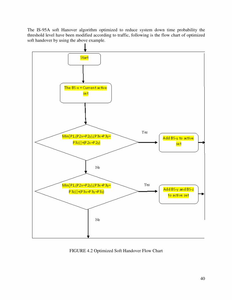
The IS-95A soft Hanover algorithm optimized to reduce system down time probability the
threshold level have been modified according to traffic, following is the flow chart of optimized
soft handover by using the above example.
FIGURE 4.2 Optimized Soft Handover Flow Chart
41
CHAPTER 5: RESULTS AND CONCLUSIONS
5.1 Results and Conclusions
Now after discussion and research work we concluded that extra resource consumption and
macro diversity have the weakened the downlink power during the soft handover in WCDMA
technique. The downlink capacity will be improved by getting optimum power control scheme
good cell selection techniques and the by adopting the optimize radio parameters. There is an
exchange between macro diversity and extra resource management to get a better system level
performance since the macro diversity is directly proportional to the link level performance.
There is a need to adopt new power scheme to get the better division of power and that power
scheme should be designed specially for WCDMA system rather than the old and conventional
power scheme. Because the conventional power scheme causes interference and it also doesn’t
get full advantages form macro diversity so to obtain a system which can by pass high soft
handover, can handle high fading and with improved downlink performance the new power
scheme must be implemented.
The Capacity gain is directly related to the handover threshold which has been obtained from the
handover optimization so it has been concluded that the new power scheme and the handover
optimization can really boost up the downlink capacity.
5.2 Future Research Work
In this report we tried to focus the main aspect that affect the overall capacity of the network
during the soft handover process in WCDMA system but there are many aspects which have not
been covered in this report. When we talk about future research work then one should pay more
attention on to the quality of Service of the system. The QoS is essential to offer real time service
which is the vital aspect of UMTS system. When studying the End to end delay of an observed
connection and the coefficient of errors of the block parameters which has been affected by the
soft handover it will be found some interesting result those can be effect the UMTS system
performance.
It is also important for future research to study the effect of characteristics of different channels
on to the capacity of the system and there is a need to find a new power scheme to get the better
division of power and that power scheme should be designed especially for WCDMA system
rather than the old and conventional power scheme.
In the End the future research must be focused to get different algorithms and the new optimized
power control schemes to get a better network.
42
REFERENCES
[1] Digital Cellular Tele Communications System (Phase 2+) (GSM) UMTS Network
Architecture (3GPP TS 23.002 Release 5)
[2] Mobile Communications by Jochen Schiller
[3] http://en.wikipedia.org/wiki/Umts (3-03-2008, 3:55am)
[4] Vijaya Chandran Ramasami “Advanced Mobile Phone Service – An Overview”
http://www.telfor.rs/telfor2004/radovi/RK-4-12.pdf
[5] Thomas Neubauer “UMTS – Universal Mobile Telecommunications System”, Research
Group Mobile Communications, Technical University Wien
http://www.nt.tuwien.ac.at/mobile/projects/UMTS/en/
[6] H. Holma & A. Toskala ”WCDMA for UMTS – Radio Access For Third Generation
Mobile Communications”, John Wiley & Sons, Ltd 2001
[7] 3rd Generation Partnership Project, Technical Specification Group RAN, Working Group
2 (TSG RAN WG2), “General UMTS Architecture”, 3G 23.101 v3.0.1, April 1999
[8] www.umtsworld.com
[9] Jussi Laukkanen “UMTS Quality of Service concept and Architecture”, University of
Helsinki, 4-5-2000
[10] UMTS, UMTS/IMT-2000 “Assessing Global Requirements for the Next Century”,
Report No. 6, UMTS Forum, London, UK, 1999
[11] http://www.umtsworld.com/technology/UMTSChannels.htm
[12] http://www.iec.org/ IEC online tutorials, UMTS
[13] Thomas Neubauer “UMTS – Universal Mobile Telecommunications System”, Research
Group Mobile Communications, Technical University Wien
http://www.nt.tuwien.ac.at/mobile/projects/UMTS/en/
[14] http://www.ittc.ukans.edu/~rvc/documents/865/865_amps.pdf
[15] http://www.freepatentsonline.com/5828659.html
[16] H. Holma & A. Toskala ”WCDMA for UMTS – Radio Access For Third Generation
Mobile Communications”, John Wiley & Sons, Ltd 2001
43
[17] Jussi Laukkanen “UMTS Quality of servive concept and Architecture”, University of
Helsinki, 4-5-2000
[18] http://www.ericsson.com/technology/tech_articles/WCDMA.shtml
[19, 20] http://oldwww.com.dtu.dk/research/networks/OPNET/UMTS_handover.pdf
[21] UMTS, UMTS/IMT-2000 “Assessing Global Requirements for the Next
[22] http://www.umtsworld.com/technology/handover.htm
[23] http://www.umts-forum.org/
[24] Thomas Neubauer “UMTS – Universal Mobile Telecommunications System”, Research
Group Mobile Communications, Technical University Wien
http://www.nt.tuwien.ac.at/mobile/projects/UMTS/en/
[25] http://privatewww.essex.ac.uk/~fleum/weas.pdf
[26] http://www.freepatentsonline.com/6430414.html (3-02-2008, 5:35pm)
[27] http://www.informit.com/articles/article.aspx?p=24904&seqNum=6 (2-03-2008)
[28] Riku Jäntti “Lecture material WCDMA course”, University of Vaasa, Finland, Spring
2003.
[29] 3rd Generation Partnership Project, Technical Specification Group RAN, Working Group
2 (TSG RAN WG2), “Radio Resource Management Strategies”, 3G TR 25.922, V2.0.0,
December 1999.
[30] 3rd Generation Partnership Project, Technical Specification Group RAN, Working Group
2 (TSG RAN WG2), “Radio Resource Management Strategies”, 3G TR 25.922, V2.0.0,
December 1999
[31, 32] B. Hashem and E. L. Strat, “On the Balancing of the Base Station Transmitted
Powers during Soft Handoff in Cellular CDMA Systems,” Proceedings of ICC’2000, vol.
3, pp. 1497-1501, 2000
[33] Lauro Ortigoza-Guerrero, A. Hamid Aghvami, ”A Prioritized Handoff Dynamic Channel
Allocation Strategy for PCS” IEEE VOL. 48, NO. 4, JULY 1999
[34] Aruna Uppendra Jayasuriya “Improved Handover Performance Through Mobility
Predictions”, University of South Australia, 31 August 2001