issue focus forging maintenance using fast-forge
TRANSCRIPT

Technologies and Processes for the Advancement of Materials
OCTOBER 2021thermalprocessing.com
USING FAST-FORGE TO PRODUCE NEAR NET SHAPE FORGINGS FROMSURPLUS AM POWDER
ISSUE FOCUS ///
COMPANY PROFILE ///
Cor-Met Inc.
FORGING / MAINTENANCE

LEGENDARYP E R F O R M A N C E
a 248-596-9000premierfurnace.com • [email protected]
PREMIER FURNACE SPECIALISTS, INC.IS YOUR TRUSTED SOURCE FOR YOURTHERMAL PROCESSING EQUIPMENT.
FROM BEAVERMATIC STANDARD DESIGNS TO CUSTOM SOLUTIONS
23850 Freeway Park DriveFarmington Hills, MI 48335

LEGENDARYP E R F O R M A N C E
a 248-596-9000 premierfurnace.com • [email protected]
PREMIER FURNACE SPECIALISTS, INC. IS YOUR TRUSTED SOURCE FOR YOUR THERMAL PROCESSING EQUIPMENT.
FROM BEAVERMATIC STANDARD DESIGNS TO CUSTOM SOLUTIONS
23850 Freeway Park DriveFarmington Hills, MI 48335

2 OCTOBER 2021
CONTENTS ///
26USING FAST-FORGE TO PRODUCE NEAR NET SHAPE FORGINGS FROM SURPLUS AM POWDERSmall- to medium-sized forgings can be produced in two simple steps from powder and that different titanium alloys with slightly different properties can be used in different regions of the part. FAST-forge of dissimilar alloys provides an opportunity for engineers and designers to better use alloys in specific locations.
SUPPLYING WELDING WIRE FOR THE REPAIR OF FORGING TOOLSCOR-MET manufactures a wide selection of cored welding wire made of alloy steels to nickel and cobalt-base alloys available for resistance to high temperatures, abrasion, and impacts.
THE IMPORTANCE OF PREVENTATIVE MAINTENANCEThe right preventative maintenance plan can offer increased performance and efficiency while minimizing downtime.
AC7102 CHECKLIST REVIEW, PART 5A look at the most challenging part of a heat-treat audit — pyrometry — and how it relates to AC7102/8. 36
COMPANY PROFILE ///
COVER PHOTO: SHUTTERSTOCK (2) / ILLUSTRATION BY RICK FRENNEA
40
32

thermalprocessing.com 3

4 OCTOBER 2021
Thermal Processing is published monthly by Media Solutions, Inc., 266D Yeager Parkway Pelham, AL 35124. Phone (205) 380-1573 Fax (205) 380-1580 International subscription rates: $105.00 per year. Postage Paid at Pelham AL and at additional mailing offices. Printed in the USA. POSTMASTER: Send address changes to Thermal Processing magazine, P.O. Box 1210 Pelham AL 35124. Return undeliverable Canadian addresses to P.O. Box 503 RPO West Beaver Creek Richmond Hill, ON L4B4R6. Copyright © 2006 by Media Solutions, Inc. All rights reserved.
No part of this publication may be reproduced or transmitted in any form or by any means, electronic or mechanical, including photocopy, recording, or any information storage-and-retrieval system without permission in writing from the publisher. The views expressed by those not on the staff on Thermal Processing magazine, or who are not specifically employed by Media Solutions, Inc., are purely their own. All “Update” material has either been submitted by the subject company or pulled directly from their corporate website, which is assumed to be cleared for release. Comments and submissions are welcome and can be submitted to [email protected].
DEPARTMENTS ///
UPDATE ///New Products, Trends, Services & Developments
Q& A ///
RESOURCES ///
OCTOBER 2021 VOLUME 10 / NUMBER 10
»L&L Furnace gets order for gas fired, car bottom furnace.»Metalloinvest hires Tenova to revamp OEMK furnace.»Bodycote showcases AM post-processing solutions.
Marketplace 44Advertiser index 47
8
JEFF MARSHALLVP AND GENER AL MANAGER /// ME TALLURGICAL HIGH VACUUM CORP
HOT SEAT ///In spray quenching, hot components are cooled down during contact with a liquid quenchant, usually through three stages. 22
QUALITY COUNTS ///When faced with specification changes, it’s a quality rep’s duty to adapt processes to comply with the revisions. 24
METAL URGENCY ///Evaluating recipe design for low pressure carburization processing of medium and high-alloy steel using simulation. 20
48
International Federation for Heat Treatment (IFHTSE)
The international association whose primary interest is heat treatment and surface engineering shares news of its activities to promote collaboration
on issues affecting the industry. 16Industrial Heating Equipment Association (IHEA)
The national trade association representing the major segments of the industrial heat processing equipment industry shares
news of it’s activities, training, and key developments in the industry. 18

SDB SERIES BATCH DRAW OVEN 40 Standard Models • Electric or Gas Heat
Wisconsin Oven Corporation2675 Main Street • PO Box 873 East Troy, WI 53120
WISOVEN.COM
Wisconsin Oven is a brand of Thermal Product Solutions, LLC
• Standard sizes tomatch most heattreat lines
• Temperaturesto 1,400° F
• High capacityrecirculation blowerfor outstanding uniformityand heating rates
• Available hearths include pier, skid,roller rails, & full width rollers
• Chain guides, charge cars and quenchtanks also available
• Available with our exclusive EnergyEfficient E-Pack™ oven upgrade (seewww.oven-epack.com for further info)
• Built to Last! Backed by our Exclusive andUnprecedented 3-Year WOW™ warranty
• Additional sizes and features availableupon request
Available with DataSense
Technologies™ IoT Based Performance Monitoring System
The Ultimate Draw Batch Oven:
2021 WOC SDB Ad 8.375x10.875.indd 12021 WOC SDB Ad 8.375x10.875.indd 1 5/19/21 8:38 AM5/19/21 8:38 AM

6 OCTOBER 2021
FROM THE EDITOR ///
CALL FOR ARTICLES Have a technical paper or other work with an educational angle? Let Thermal Processing publish it. Contact the editor, Kenneth Carter, at [email protected] for how you can share your expertise with our readers.
Coop wants to use this one for the website
Vertical Logo Horizontal Logo
PUBLISHED BY MEDIA SOLUTIONS, INC.P. O. BOX 1987 • PELHAM, AL 35124
(800) 366-2185 • (205) 380-1580 FAX
David C. CooperPRESIDENT
Teresa CooperOPERATIONS
David C. CooperPUBLISHER
EDITORIALKenneth Carter
EDITOR
Jennifer JacobsonASSOCIATE EDITOR
Joe CroweASSOCIATE EDITOR | SOCIAL MEDIA
SALESDave Gomez
NATIONAL SALES MANAGER
Ben KeatenREGIONAL SALES MANAGER
CIRCULATIONTeresa Cooper
MANAGER
Jamie WillettASSISTANT
DESIGNRick Frennea
CREATIVE DIRECTOR
Michele HallGRAPHIC DESIGNER
CONTRIBUTING WRITERS
KENNETH CARTER, [email protected](800) 366-2185 x204
Another tradeshow in the booksy the time you read this, Heat Treat 2021 will be a four-week memory, but for me and my team — as I’m writing — we are still recuperating from our trip to St. Louis, but in a good way.
Admittedly, the shadow of a pandemic still kept many away, but the ones who made it used the in-person tradeshow to reconnect with established contacts while making many new ones as well.
The Thermal Processing staff felt like we had a very productive show — and a fun one, too.How fun was it for us? Check out our website to see some of the fun we had with a
few of the exhibitors. Our social media director made videos of some of you, asking you three important questions. Well, maybe two important questions, depending on how serious you find snack food. Mind blown? Then, check out our videos for the big reveal.
A big thanks to all of the exhibitors who participated. Judging from the videos, it sure looks like you had as much fun as we did.
As we jump into fall, our October issue is filled with some interesting information to whet your interests.
With a spotlight on maintenance and forging, two of our Focus articles take a look at these important topics.
First up is an article on FAST-forge of novel Ti-6Al-4V/Ti-6Al-2Ss-4Zr-2Mo bonded, near net shape forgings from surplus AM powder. I know; it’s a mouthful, but an interesting read, nonetheless.
Next up is a good look at the importance of preventative maintenance from Noble Industrial Furnace.
Last, but not least, is the final part of frequent contributor and columnist Jason Schulze’s five-part series on the AC7102/1 checklist. If you missed any of the earlier seg-ments, head to our website to check them all out.
You’ll find all that and so much more in this month’s issue, so be sure and spend some quality time reading our company profile, Q&A, columns, and industry updates.
I hope you enjoy it as much as we enjoyed putting it all together for you.As always, thanks for reading!
B
GAVIN BAXTERJENNIFER BIELENMARTIN JACKSON
SHAUN KIMOLIVER LEVANO
DAVID LUNN
D. SCOTT MACKENZIEJACOB POPE
JASON SCHULZEJUSTIN SIMS
ADAM TUDBALLNICHOLAS WESTON

thermalprocessing.com 7
MadgeTech data loggers are designed, manufactured and serviced in the USA and distributed worldwide.
The MadgeTech Titan S8 is a portable, multi-use data logger with eight input channels, one configurable alarm output and a user-friendly touchscreen interface. The Titan S8 is a complete, all-in-one solution that does not require a PC or any downloaded software for operation. This means the device is truly ready
for use at a second’s notice.
FEATURES• Simultaneously Records 8 Different
Parameters
• Supports Thermocouple, RTD or Thermistor Probes
• Download Data Via USB
• 1 GB Internal Memory
• Real-Time FFT
• Programmable Engineering Units
• No Required Software
• Rechargeable Battery
• Charger Included
• 1 Configurable Alarm Output
For more information on the MadgeTech Titan S8, scan the QR code, call (603) 456-2011 or email [email protected].
(603) 456-2011madgetech.com
6 Warner RoadWarner, NH 03303
5 INCHTOUCH SCREEN
ON-SCREEN KEYBOARD
16-BIT HIGH RESOLUTION
WIFICONNECTIVITY
ETHERNETCONNECTIVITY
DISPLAY ROTATION
REAL-TIME DATA VISUALIZATION
ON-SCREEN ALERTS
WIRING DIAGRAM
180°
8 OCTOBER 2021
UPDATE /// HEAT TREATING INDUSTRY NEWS
SEND US YOUR NEWS Companies wishing to submit materials for inclusion in Thermal Processing’s Update section should contact the editor, Kenneth Carter, at [email protected]. Releases accompanied by color images will be given first consideration.
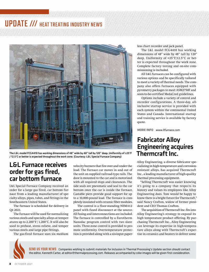
L&L Furnace receives order for gas fired, car bottom furnaceL&L Special Furnace Company received an order for a large gas fired, car bottom fur-nace from a leading manufacturer of spe-cialty alloys, pipes, tubes, and fittings in the Southeastern United States.
The furnace is scheduled for delivery in Q4 2021.
The furnace will be used for normalizing various steels and specialty alloys at temper-atures up to 2,200°F / 1,200°C. It will also be used to preheat, stress relieve, and temper various steels and large pipe fittings.
The gas-fired furnace uses six medium
velocity burners that fire over and under the load. The furnace car moves in and out of the unit on supplied railroad-type rails. The door is mounted to the car and is motorized with all required stops and clearances. The side seals are pneumatic and seal to the car bottom once the car is inside the furnace. Castable piers provide good support for up to a 10,000-pound load. The furnace is com-pletely insulated with ceramic fiber modules.
The control is a floor-standing NEMA12 panel with fused disconnect at the source. All fusing and interconnections are included. The furnace is controlled by a Eurotherm Nanodac program control with two slave units. Three-zone control is provided to pro-mote uniformity. Overtemperature protec-tion is provided along with a six-input paper-
less chart recorder and jack panel.The L&L model FCG4410 has working
dimensions of 48” wide by 48” tall by 120” deep. Uniformity of ±25°F/12.5°C or bet-ter is expected throughout the work zone. Complete factory testing and on-site com-missioning is included.
All L&L furnaces can be configured with various options and be specifically tailored to meet a variety of thermal needs. The com-pany also offers furnaces equipped with pyrometry packages to meet ASM2750F and soon-to-be-certified MedaCred guidelines.
Options include a variety of control and recorder configurations. A three-day, all-inclusive startup service is provided with each system within the continental United States and Canada. International startup and training service is available by factory quote.
MORE INFO www.llfurnace.com
Fabricator Alloy Engineering acquires Thermcraft Inc.Alloy Engineering, a diverse fabricator spe-cializing in high-temperature and corrosion-resistant alloys, has acquired Thermcraft Inc., a leading manufacturer of high-quality thermal processing equipment.
“Selling Thermcraft was easier knowing it’s going to a company that respects its history and values its employees like Alloy Engineering does. Tom would be happy to know there is a bright future for Thermcraft,” said Nancy Crafton, widow of former presi-dent and CEO Thomas Crafton.
The acquisition of Thermcraft Inc. fits into Alloy Engineering’s strategy to expand its high temperature product offering. By pur-chasing Thermcraft Inc., Alloy Engineering can leverage its expertise in high-tempera-ture alloys along with Thermcraft’s exper-tise in ceramics and heaters to deliver some
The L&L model FCG4410 has working dimensions of 48” wide by 48” tall by 120” deep. Uniformity of ±25°F / 12.5°C or better is expected throughout the work zone. (Courtesy: L&L Special Furnace Company)
12500 Grand River Rd Brighton, MI 48116 810-227-3251 www.cor-met.com
“Ask for a weld shop tune up” Cor-Met, Inc. 12500 Grand River Rd, Brighton Ml 48116
810-227-3251 • cor- met.com • [email protected]
Manufacturing Welding Products and Equipment for Forge Die Repair
• Flux Core Wire• Electrodes• Flood Welding• Training• Equipment• Engineering
ASK FOR A WELD SHOP TUNE UP

thermalprocessing.com 9
12500 Grand River Rd Brighton, MI 48116 810-227-3251 www.cor-met.com
“Ask for a weld shop tune up” Cor-Met, Inc. 12500 Grand River Rd, Brighton Ml 48116
810-227-3251 • cor- met.com • [email protected]
Manufacturing Welding Products and Equipment for Forge Die Repair
• Flux Core Wire• Electrodes• Flood Welding• Training• Equipment• Engineering
ASK FOR A WELD SHOP TUNE UP

10 OCTOBER 2021
UPDATE /// HEAT TREATING INDUSTRY NEWS
innovative products to both existing and new customers and markets.
“I am excited and eager to take the reputa-tion built by the Crafton family along with the Thermcraft employees and grow it to the next level. By merging the core competencies of both companies and taking innovative solu-tions to market, we will provide a solid future for both of our companies,” said Lee Watson, president and CEO of Alloy Engineering.
Since 1943, Alloy Engineering in Berea, Ohio, has been an innovative leader in the design and manufacture of high-quality alloy equipment for high-temperature and corrosive industrial applications in installa-tions around the world. Built on a founda-tion of engineering, fabrication, and high-temperature materials expertise, Alloy serves customer in a variety of applications and industries including aerospace, chemi-cal processing, heat treat, powder metals, steel and metal process, and power gen.
MORE INFO www.alloyengineering.com
Refurbished MIM/AM furnace gets new binder technologySolar Atmospheres of Western PA acquired a used VFS HL50 external quench vacuum fur-nace at an auction in the Philadelphia area. The main objective of this purchase was to retrofit this older furnace with a newer hot zone and pumping technology that will help minimize and target the condensation of detrimental binders evaporating out of MIM injection molded parts.
Solar’s maintenance team was respon-sible for refurbishing the furnace to its cur-rent standard. Solar Manufacturing, led by owner and CEO William Jones, designed the technology and the apparatus needed to consolidate the binders into one central location, thus minimizing the cleaning downtime the Solar staff was experiencing. This includes a completely new hot zone, a binder pumping port, and a second vacuum pump. The collaborative effort ensured both projects came together seamlessly.
By mid-October, the high production MIM sinter job will be fully transferred from current Solar vacuum furnaces to this dedicated and refurbished vacuum furnace.
After multiple sintering runs, Solar will then have the data to compare the downtime of a traditional vacuum furnace versus the newly designed debind/sinter furnace. Solar looks forward to providing the MIM world with this new, critical processing information.
MORE INFO solaratm.com
Lucifer Furnaces ships seventh furnace to OEMLucifer Furnaces has shipped a seventh large dual chamber 8000 Series furnace to a U.S. auto manufacturer.
Each chamber is 24” H x 24” W x 36” L. This heavy-duty furnace-over-oven features 12-gauge sheet steel construction with rein-forced members for a solid framework. The upper hardening chamber heats with 45 KW power to banks of elements on sides, door and back. The heating elements are designed with heavy gauge wire mounted in remov-able holders. The upper chamber cast hearth plates support the workload and can be eas-ily replaced without disturbing the heating elements. The lower tempering oven with 20 KW power features a stainless-steel liner shielding heating elements from the work-load. This liner was designed as a three-sided liner with a cast hearth plate for durability. A high cfm, 1/2 hp fan recirculates air past the elements and back through the chamber in a uniform pattern.
This unit was customized with a free-standing control panel providing the ability to separate control operation from the fur-nace environment. Each chamber has been outfitted with Honeywell multi-program controllers with a high limit backup control-ler to prevent temperature excursion events.
MORE INFO www.luciferfurnaces.com
Watervliet Arsenal selects Surface® Combustion Surface® Combustion, Inc. has shipped a new Ion nitriding thermal processing furnace system for Watervliet Arsenal.
Watervliet was familiar with Surface
Solar Atmospheres of Western PA will use a refurbished vacuum furnace to for data to use in improving processing. (Courtesy: Solar Atmospheres of Western PA)
Lucifer Furnaces has shipped a seventh large dual chamber 8000 Series furnace to a U.S. auto manufacturer. (Courtesy: Lucifer Furnaces)

thermalprocessing.com 11
Combustion’s multitude of furnace offerings and awarded a contract to Surface so they could again bring their processing capability in-house. Adding control to the supply chain for product was one of the many reasons Watervliet added an ion nitriding thermal processing furnace system to its plant.
Surface Combustion values customer relationships and believes that an equip-ment purchase is the beginning of some-thing more than a finite transaction. Surface Combustion has been working with the Watervliet Arsenal location for more than 40 years.
“It is always great to see customers com-ing back to Surface because they appreciate our incredible product lines as well as our engineering capabilities and long-standing relationships,” said Ben Bernard, vice presi-dent of marketing at Surface.
The Surface Combustion ion nitriding system, with full controls, will be fully installed and commissioned in a horizon-tal configuration. This configuration best
suits the facility and Watervliet Arsenal’s processing needs, and will also include pro-cess development.
This is the second ion nitriding furnace Surface has supplied to Watervliet. The first was more than 40 years ago.
MORE INFO www.surfacecombustion.com
Tenova Pomini Digital Texturing™ gets LCA certificationTenova, a leading developer and provider of sustainable solutions for the green transi-tion of the metals industry, has attained an important milestone. Pomini Tenova, world-wide leader in the production of roll grind-ers, has successfully concluded the life cycle assessment (LCA) analysis of Pomini Digital Texturing™ (PDT™) — a breakthrough tech-nology for surface texturing of rolling mill work rolls.
The study is the first one of this kind in the sector of metal surface finishing machines, enabling the PDT technology to receive the certification in compliance with the ISO 14025:2006 standard and the General Programme Instruction 4.0. As positive result of the auditing undertaken in March 2021, the LCA analysis was registered on the EPD®
The Surface Combustion ion nitriding system, with full controls, will be fully installed and commissioned in a horizontal configuration. (Surface® Combustion, Inc.)
HeatAd_3_5x4_625_Layout 1 2/8/17 2:12 PM Page 2
Handle High Temperatures and Harsh Operating Conditions with Ease.
GRAPHALLOY® BearingsCan Take the Heat
Yonkers, NY USA
• Survives when others fail• Run hot, cold, wet or dry• Corrosion resistant• Self-lubricating• Low maintenance• -400˚F to 1000˚F (-240˚C to 535˚C)• Ovens, furnaces, conveyors,
mixers, dampers
Handle High Temperaturesand Harsh OperatingConditions with Ease.
+1.914.968.8400 • www.GRAPHALLOY.com
Yonkers, NY USA
GRAPHALLOY® Bearings Work Where Others Won’t
H2
HeatAd_3_5x4_625_Layout 1 2/8/17 2:12 PM Page 2
• Survives when others fail• Run hot, cold, wet or dry• Corrosion resistant• Self-lubricating• Low maintenance• - 400˚F to 1000˚F (-240˚C to 535˚C)• Ovens, furnaces, conveyors, mixers, dampers
H3
3150 BOX FURNACEFOR AMS 2750
www.atspa.com | [email protected] | 724-283-1212LEARN MORE TODAY!
Ceramic Blanket Fiber Insulation
TUSThermocouple Port
Temperature Survey Rack
TUS Temperature Recorder
Adjustable Leg LevelersATS Manufactured
Heating Elements

12 OCTOBER 2021
UPDATE /// HEAT TREATING INDUSTRY NEWS
Portal – the platform of the International EPD® System, the world’s leading global LCA program operating in accordance with the ISO 14025, TS/14027, 14040, a.o. standards – and is now accessible to all users.
This represents a significant milestone for Pomini Tenova’s leading-edge PDT tech-nology, certifying its eco-friendly features and performances, and brings further value to the numerous customers who have already chosen it.
“PDT is Pomini’s f lagship technology: a clean, cost effective, versatile, safe, and multi-patented process. I strongly believe that the life cycle assessment analysis and related certifications add on to the unique value of our solution, embracing the sustain-ability concerns and expectations of our stakeholders,” said Paolo Gaboardi, Tenova executive vice president.
MORE INFO www.tenova.com
Mercury Marine, ECM advance heat treating processesMercury Marine of Fond du Lac, Wisconsin, recently launched a plan to upgrade its heat-treating capabilities with a move to the low-pressure carburization and high-pressure gas quench system. Partnering with ECM Technologies, the new plan incorporates completely automated Nano vacuum heat-
treating systems. The innovative Nano system incorporates 20 bar nitrogen gas quenching along with low pressure carbu-rizing (aka vacuum carburizing). The Nano, with its versatile configuration, will oper-ate several different carburizing, harden-ing, and spheroidizing processes simultane-ously. This change marks a departure from Mercury’s traditional atmospheric carburi-zation and oil quench system while benefit-ing from advantages that come with vacuum processing, including:
» Innovative vacuum heat treating in lieu of traditional atmosphere (elimina-tion of intergranular oxidation and highly repeatable process with consistent results).
» Employs preventative maintenance planning, remote system status access, and facility information systems integration.
» Relocates heat treat from a secondary location to the clean, controlled environ-ment of the machining centers.
» Converts to small batch processing principles to maximize process efficiency.
» State-of-the-art growth with ECM’s advanced system automation and robot capa-bility with load building and breakdown.
» Controls downstream operations by matching incoming dunnage with exiting workpieces.
» Takes advantage of vapor and vacuum-based pre-cleaning technology to remove multiple machining lubricants.
» Incorporates cryogenic and tempering processes within the automated system.
The system uses all CFC workload fix-
tures and ECM’s advanced automation fix-ture tracking to maintain a precise cycle count to know fixture life. This improve-ment for Mercury significantly reduces energy consumption and process cost per piece. Additionally, the vacuum process takes their heat treatment to a near-zero emissions for drivetrain components pro-cessed within the system.
MORE INFO www.mercurymarine.com www.ecm-usa.com
Bodycote showcases AM post-processing solutionsTo share its expertise in thermal processing services and solutions such as hot isostatic pressing (HIP), EDM, heat treatment, and other processes for additive manufactur-ing, Bodycote exhibited at RAPID + TCT, the premier additive manufacturing (AM) and 3D printing event in the United States, in September.
Bodycote, a world leading provider of heat treatment and specialist thermal process-ing services, specializes in the treatment of parts and components used in a wide range of industries. Bodycote’s facilities provide a complete service solution for metal parts built by the additive manufacturing process, including stress relief to minimize distor-tion and residual stress, EDM to prepare the component for hot isostatic pressing, heat treatment, or HIP, to remove microporosity, and associated quality assurance testing.
“Our thermal processing services play a
Pomini Tenova has successfully concluded the life cycle assessment (LCA) analysis of Pomini Digital Texturing™ (PDT™). (Courtesy: Tenova)
Bodycote specializes in the treatment of parts and components used in a wide range of industries. (Courtesy: Bodycote)

thermalprocessing.com 13
significant role in additive manufacturing post-processing, to optimize the mechani-cal properties of the components. Almost all metal parts built by additive manufactur-ing require secondary treatments to make them suitable for their intended use. Our complete service model will ensure the most cost-effective and time-saving option for 3D printed metal parts,” said Jamie Kuriger, regional sales manager (USA), Bodycote.
MORE INFO www.bodycote.com
Metalloinvest hires Tenova to revamp OEMK furnaceTenova Italimpianti, a leading technologies and equipment supplier for the world of industrial furnaces, recently received a con-tract from Metalloinvest, a leading global iron ore and HBI producer and supplier and one of the regional producers of high-quality steel, for the reconstruction of the heating furnace nr. 2 in the second rolling unit of Alexey Ugarov OEMK in Russia.
As part of the reconstruction, the new design of the walking hearth furnace includes the modification of the combus-tion system using the new technology burn-ers with the aim to improve efficiency and reduce emissions through a sophisticated combustion control system.
The project aims also to eliminate the formation of a range of defects in the prod-ucts, allowing the client to reduce costs and
increase volumes of high-quality long prod-ucts (Special Bar Quality, SBQ).
“Metalloinvest chose Tenova to manage this complex project because of our tech-nical expertise and reliability in terms of time scheduling; we are very pleased to co-operate once again with this important Russian player. In a very competitive mar-ket with a continuous evolution of quality requirements, our clients can keep on top of this fast innovation pace thanks to our technological solutions. Together with our qualified personnel they are able to find the right optimizations for their equip-ment, so to obtain better performances and reduce operating costs,” said Marcello Tomolillo, service area manager at Tenova Italimpianti.
The heating furnace is planned to be com-missioned in December 2022.
MORE INFO www.tenova.com
Seco/Vacuum sells VAB furnace to global aircraft supplierSeco/Vacuum, a Seco/Warwick Group brand, has sold a vacuum aluminum brazing (VAB) furnace to an international aircraft compo-nent supplier.
The furnace is designed to meet tight temperature tolerances of ±3°C, incorporat-ing a powerful high-vacuum system with diffusion pump. The furnace is equipped with six temperature control zones and can
Innovative Infrared Technology
Ult
ra-f
ast.
Our
new
hig
h-sp
eed
pyro
met
er C
T 4M
w
ith u
ltra-
fast
exp
osur
e tim
e of
90
μs
is id
eally
sui
ted
for f
ast h
igh-
volu
me
pr
oduc
tion
and
pack
agin
g pr
oces
ses.
Pyr
omet
ers.
IR C
amer
as. A
cces
sorie
s. S
oftw
are.
W
e m
easu
re te
mpe
ratu
re n
on-c
onta
ct
from
–50
°C to
+30
00 °C
. Vis
it: w
ww
.opt
ris.c
om
when temperature matters
New
Tenova Italimpianti received a contract from Metalloinvest for the reconstruction of a heating furnace at Alexey Ugarov OEMK in Russia. (Courtesy: Metalloinvest)

14 OCTOBER 2021
UPDATE /// HEAT TREATING INDUSTRY NEWS
accommodate loads with dimensions up to 36"´28" 4́8" / 900´700´1,200mm (WxHxD).
The new furnace joins other Seco/Warwick Group vacuum furnaces installed at this location. The prior acquisitions pro-vided a basis of credibility because of their successful performance; however, the deci-sion to go with Seco/Vacuum hinged as much
on the supplier’s newer proven technologies and collaborative approach to accommodate the customer’s unique requirements.
A VAB furnace allows brazing of alumi-num parts for applications where use of braz-ing flux is not permitted due to corrosion potential. This feature applies especially to parts used in critical applications such as
aircraft. Seco/Vacuum’S VAB furnace oper-ates in deep vacuum and delivers perfect temperature uniformity, meeting Class 1 requirements by AMS2750F.
Vacuum aluminum brazing is especially useful in aeronautical and aerospace appli-cations because of the challenging speci-fications that must be met. For any firm conducting its own aluminum brazing in-house or for those heat-treat shops with opportunities to work with aerospace cus-tomers (especially for military applications), and aerospace components suppliers, Seco/Warwick’s Group VAB offers a sound solu-tion, especially when coupled with a collab-orative working philosophy.
Delivery is scheduled for early 2022.
MORE INFO www.secowarwick.com
Ipsen sees demand from mid-size manufacturersAs more mid-sized companies recover from pandemic related disruptions, Ipsen is see-ing a surge in interest for standardized equipment.
Ipsen reports a steady increase of orders for Titan vacuum furnaces this year, with five in July alone. That’s a substantial increase over the same period in 2020, and a fundamental shift from the more spe-cialized equipment that drove increased demand in the first half of this year.
Customers range from those in cutting tools and machinery to additive manufactur-ing and aerospace. As businesses gain confi-dence in a stabilizing economy and antici-pate increased production demand, many are resuming pre-COVID investment plans.
Despite supply chain challenges through-out the manufacturing sector, the Titan still has the best lead time in the industry. Its compact size, versatility, and global operat-ing platform make the Titan an attractive option for those looking for a high-perfor-mance turnkey solution with fast delivery. Customers also consider Ipsen’s excellent service and support, technical expertise, and product quality as key factors in their purchasing decisions.
MORE INFO www.ipsenusa.com/titan
Heat on Demand!
Thermcraft is an international leading manufacturer of thermal
processing equipment. With over 40 years of experience,
we can work with you to find a solution that fits your needs. At Thermcraft, customer service is
our #1 priority!
+1-336-784-4800www.thermcraftinc.com [email protected]
High Temperature Heating Elements• Ceramic Refractory Heating Elements• Vacuum Formed Ceramic Fiber Heating Elements• Heavy Duty Cast Refractory Plate Heating Elements• Replacement Heating Elements for all OEM’s• Vacuum Formed Insulation Packages• Custom CNC Machined Insulation Shapes• Custom Designed Heating Elements for R&D
Applications• Heating Elements can be used for Custom Built
Furnace Applications• Made in the USA
ThermalProcessingDec2018.indd 1 12/11/2018 1:43:51 PM

thermalprocessing.com 15
VERTICAL BOTTOM LOADINGVACUUM FURNACE
PROUDLY MADE IN THE USATHE BR IGHTEST SOLUT IONS THROUGH INGENUIT Y
VBL SERIESSolar Manufacturing’s VBL Series of vertical bottom loading vacuum furnaces are designed to process a wide variety of aircraft engine components such as blades, rings, stators, nozzles and structural parts such as forgings for wings, landing gear, and many others. Our innovative engineering integrates our energy efficient hot zones, feature-rich SolarVac® automated controls, and our high performance gas quench systems for 2 bar or higher quench pressures. Matched with our outstanding customer service and reliable aftermarket support, we will keep your furnace running year after year.
VERTICAL BOTTOM LOADING
MENTOR® &MENTOR® PRO
INTERNAL QUENCH
EXTERNAL QUENCH
HORIZONTAL CAR BOTTOM
solarmfg.com
Give us a call to learn more about our vacuum furnace ingenuity.

27th IFHTSE Congress, European conference on heat treatment in Austria
The 27th IFHTSE Congress will be in Salzburg, Austria, September 5-8, 2022, at the Wyndham Grand Salzburg Conference Center. The conference chairs are Eva Troell, RISE IVF Research
Institutes of Sweden (Sweden and present President of IFHTSE); Masahiro Okumiya, Toyota Technological Institute (Japan and upcoming President of IFHTSE), and Reinhold Schneider, University of Applied Sciences Upper Austria (Austria), and chairman of ASMET Heat Treatment Committee.
IMPORTANT DATES »Abstract submission deadline: January 31, 2022.»Notification of acceptance: March 31, 2022.»Preliminary program: April 30, 2022.»Full Paper Submission Deadline: May 31, 2022.
Please submit your abstracts (300-400 words) via the conference website: www.ifhtse-echt2022.org.
The special emphasis of ECHT2022 will be on Heat Treatment in Steel Processing. Topics include furnace design, thermomechanical treatments, quenching technology, additive manufacturing, and coating technologies.
SPOTLIGHT ON MEMBERSIFHTSE is a federation of organizations, not individuals. There are three groups of members: scientific or technical societies and asso-ciations, universities, registered research institutes, and companies.
In this segment, we will highlight our members. This month we highlight Asociace Pro Tepelné Zpracováni Kovu (Czech Association for the Heat Treatment of Metals).
The special emphasis of ECHT2022 in Austria will be on Heat Treatment in Steel Processing.
INTERNATIONAL FEDERATION OF HEAT TREATMENT AND SURFACE ENGINEERING
16 OCTOBER 2021

The Czech Association for the Heat Treatment of Metals is an independent non-political trade organization and a voluntary affili-ation of private individuals and companies. ATZK was established to bring together professional interests in the field of the heat treat-ment of metals and in the advancement of the level of this entire branch of technology. ATZK establishes and maintains organiza-tional and professional contacts with foreign associations, primar-ily the International Federation for Heat Treatment and Surface Engineering and the German company AWT (Arbeitsgemeinschaft Wärmebehandlung und Werkstofftechnik).
ATZK produces a triannual bulletin with information from the field, which keeps its members updated on its activities and events.
The president of ATZK is Ing. Pavel Stolař, CSc. [email protected].
AWT SAFETY MANUALThe Expert Committee #8 “Safety regulations in heat treatment com-panies” of German member association AWT has compiled a compre-hensive manual of heat-treatment shops. The 96-page document, full
of instructive illustrations, refers to German statutory reg-ulations and standards that, in turn, are based on underlying European legislation. It also contains a wealth of practical tips and information on imple-menting occupational safety and health effectively in the heat-treating shop. This allows the heat-treating employees to properly assess hazards and to develop proper countermea-sures for the minimization of these hazards. While the regulations vary widely across member countries, the booklet defines a “best practice” for
mitigation of safety hazards in the heat-treating shop. The down-load is free at: publikationen.dguv.de/regelwerk/dguv-regeln/3866/metals-heat-treatment-sector.
Due to the pandemic, many conferences planned for 2021 have either been delayed or canceled. Please watch this space for updates on current conference planning.
OCTOBER 26–28HK 2021HK is the largest materials technology industry meeting in Europe Cologne, Germany I www.hk-awt.de
APRIL 2022 12th Tooling Conference & Exhibition (Tooling 2022)Örebro, Sweden
SEPTEMBER 2022 27th IFHTSE Congress / European Conference on Heat TreatmentSalzburg, Austria
APRIL 20235th International Conference on Heat Treatment and Surface Engineering of Tools and DiesLiangzhu Dream Town, Hangzhou, China
NOVEMBER 13-16, 2023 28th IFHTSE CongressYokohama, Japan
For details on IFHTSE events, go to www.ifhtse.org/events
IFHTSE 2021 EVENTS
EXECUTIVE COMMITTEEEva Troell I PresidentRISE IVF Research Institutes of Sweden I Sweden
Dr. Scott MacKenzie I Past PresidentHoughton International Inc. I USA
Prof. Masahiro Okumiya I Vice PresidentToyota Technological Institute I Japan
Dr. Stefan Hock I Secretary GeneralIFHTSE Italy
Dr. Imre Felde I TreasurerÓbuda University I Hungary
OTHER MEMBERSProf. Rafael Colas I Universidad Autónoma de Nueva Leon I Mexico
Dr. Patrick Jacquot I Bodycote Belgium, France, Italy I France
Prof. Massimo Pellizzari I University of Trento I Italy
Prof. Larisa Petrova I MADI University I Russia
Prof. Reinhold Schneider I Univ. of Appl. Sciences Upper Austria I Austria
Prof. Marcel Somers I Technical University of Denmark I Denmark
Prof. Kewei Xu I Xi’an University I China
ONLINE www.ifhtse.org I EMAIL [email protected]
IFHTSE LEADERSHIP
thermalprocessing.com 17

18 OCTOBER 2021
INDUSTRIAL HEATING EQUIPMENT ASSOCIATION
IHEA member ECCO delivers innovative solutions for the natural gas industry
Equipment Controls Company (ECCO) was founded in 1965 as a distributor of liquid measurement controls systems for Rockwell. Over the years, the company has expanded its prod-
uct lines to include manufacturers such as Pietro Fiorentini, Sensus, Romet, and EAGLE Research. ECCO has always been focused on deliv-ering innovative solutions for the natural gas industry. It distributes products to various markets including gas utility, industrial, com-mercial, and institutional. ECCO’s growth can be attributed to pro-viding complete customer satisfaction with professionalism, ethical standards, and exceptional product knowledge.
With 53 employees and growing, ECCO serves many companies within the natural gas industry, distributing to the gas utilities, industrial, commercial, institutional (ICI), and the original equip-ment manufacturer (OEM) markets. ECCO’s gas utility division sup-plies utility companies, municipalities, local distribution companies, and transmissions. Its ICI division supplies products specific to natu-ral gas distribution and measurement as well as products and sup-port for the thermal processing market.
With its gamut of expertise, ECCO is known for having experts in technology and product knowledge that includes natural gas mea-surement, gas control, and data acquisition products and services. ECCO also can supply technical support, on-line support in order to be a full-service supplier.
Within ECCO’s product line, customers will find Pietro Fiorentini’s ZERO GOVERNOR F3Z series, designed to comply with the ANSI Z21.8 standard. This family of regulators is ideal for all burner installa-tions, nozzle mixers, mixing tees, and proportional pre-mixers. Their
Dival 500 medium–low pressure gas regulator
Dival Zero Governor low pressure gas regulator
EQUIPMENT CONTROLS COMPANY (ECCO)Address: 4555 South Berkeley Lake Road, Norcross, Georgia, 30071.
Phone: 800-554-1036 or 770-441-6400 Fax: 770-448-7312
Website: www.equipmentcontrols.com
E-mail: [email protected]

thermalprocessing.com 19
IHEA seminars: Combustion and Safety Standards This fall, IHEA will be back to in-person seminars. The Combustion Seminar and Safety Standards and Codes Seminar will take place concurrently in Cleveland, Ohio November 9-10. The popular train-ing classes are instructed by industry professionals who deal with the subject matter on a daily basis. Attendees receive two days of instruc-tion with real life examples and get answers to questions from the
expert speakers. In addition, the fall seminars are supported by a tabletop exhibition filled with industry suppliers and leaders in the thermal processing world. Learning continues when attendees visit with manufacturers and suppliers; admission to the tabletop exhibi-tion is included with the seminar registration fee. Registration now open. Get complete details and register at www.ihea.org/Fall21.
function is to regulate the pressure and to maintain constant air/gas ratio.
Pietro Fiorentini’s Dival 500 Direct-Acting Gas Pressure Regulator is a series of spring loaded, diaphragm-controlled balanced plug gas regulators that are suitable for low, medium, and high pressure. Divals and shut-off device series regulators are supplied with internal sensing lines. Both the regulator and the shut-off device are preset for an optional connection to an external sensing line by the customer. They are widely used in both civil and industrial installations using natural gas, LPG, and other non-corrosive gases.
ECCO has expanded its industrial thermal processing division to meet the growing industry demand. With the recent addition of its Sandy, Utah, sales office and warehouse, the company services and supports customers across the country.
As it moves into the future, Equipment Controls Company will continue its commitment to provide exceptional service to its cus-tomers by developing industry-specific training throughout all of its market segments.
2021 IHEA FALL SEMINARSCombustion | Safety Standards & Codes
November 9 - 10InterContinental Hotel | Cleveland, OH
www.ihea.org
NOVEMBER 9–10IHEA Combustion SeminarInterContinental Hotel Cleveland I Cleveland, Ohio
NOVEMBER 9–10IHEA Safety Standards & Codes SeminarInterContinental Hotel Cleveland I Cleveland, Ohio
For details on IHEA events, go to www.ihea.org/events
IHEA 2021 CALENDAR OF EVENTS
INDUSTRIAL HEATING EQUIPMENT ASSOCIATIONP.O. Box 679 I Independence, KY 41051
859-356-1575 I www.ihea.org
20 OCTOBER 2021
METAL URGENCY ///JUSTIN SIMS
MECHANICAL ENGINEER /// DAN T E SOL U TIONS
ow pressure carburizing (LPC) processes are a popular choice in industry due to LPC’s reduced cycle time, lack of oxida-tion/decarburization at and near surface, better efficiency
and repeatability, and power savings when compared to conventional gas carburization. [1,2] Although the benefits of LPC are evident, con-trolling and designing recipes for an LPC process are different than controlling and designing gas carburizing processes.
For a gas carburization process, the carbon potential is regulated and controlled by the use of various probes, limiting the carbon avail-able at the part’s surface. Control of the carbon potential is generally sufficient to minimize carbide formation during the gas carburiza-tion of medium-alloy and some high-alloy steels. However, there is no such carbon potential control in an LPC process. Instead, a hydrocar-bon gas, usually acetylene, is introduced into the chamber for a short time and then promptly evacuated. Austenite saturation is generally obtained within a few seconds during this “boost” step, and as such, the possibility of carbide formation is high. It is therefore critical to control the gas flow rate and time duration during the boost step to ensure excessive carbide formation does not occur. After the hydro-carbon gas is evacuated, the carbon that was deposited on the surface is allowed to diffuse into the surface under a near vacuum condition. These steps are repeated until the final surface carbon and effective case depth are achieved. [2]
To show the difference on case depth and surface carbon for LPC process design using a common steel alloy used in high load applica-tions, and one in which the simple equation shown in (1) works to predict the case depth with reasonable accuracy when gas carburized, an example is presented that evaluates the differences when the recipe is designed considering and not considering carbide forma-tion in simulation. While Equation 1 works well when applied to gas carburization, it fails to properly predict the case depth when LPC is used, and carbide formation becomes significant. [3]
(1)
AISI 9310 was chosen as the steel alloy, due to its wide use in industry and its general lack of significant carbide formation during gas carburization. However, AISI 9310 can have significant carbide formation during LPC processing. DANTE’s VCarb software utility was used to design an LPC recipe given a set of final requirements. VCarb is a standalone software utility which can be used to predict the carbon, carbide, and hardness profiles for a defined LPC recipe or be used to design an LPC recipe given a set of requirements. The addition of carbide formation and dissolution predictions is critical in determining an appropriate LPC recipe for AISI 9310 using simu-lation. Several factors must be considered when modeling carbides, including carbide formation rates, carbide dissolution rates, and the effect of carbide size on the diffusivity of carbon in the austenite matrix. All of these material properties must be defined as a func-
tion of processing temperature and carbide size. As the carbides form during the boost step, they take carbon from the surface and limit the amount of carbon that can diffuse into the part. During the dif-fuse step, the carbides decompose and provide an additional carbon source.
As a first step, DANTE’s VCarb was used to determine an LPC boost-diffuse schedule for AISI 9310 not considering carbide forma-
Evaluating recipe design for low pressure carburization processing of medium and high-alloy steel using simulation.
Important to consider carbide formation during simulation
L
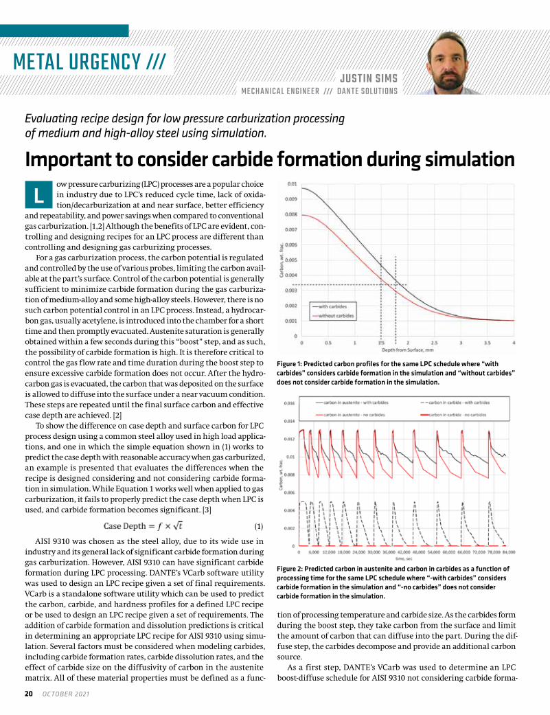
Figure 1: Predicted carbon profiles for the same LPC schedule where “with carbides” considers carbide formation in the simulation and “without carbides” does not consider carbide formation in the simulation.
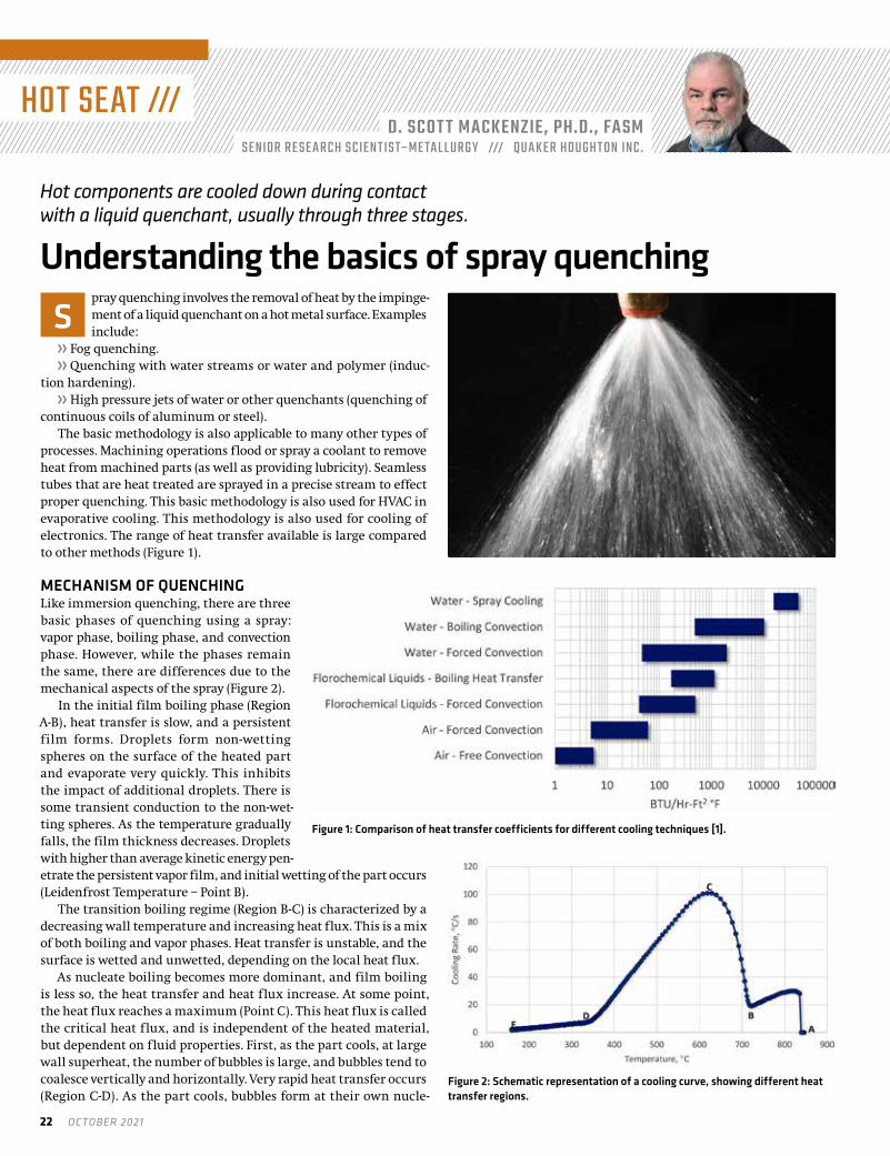
Figure 2: Predicted carbon in austenite and carbon in carbides as a function of processing time for the same LPC schedule where “-with carbides” considers carbide formation in the simulation and “-no carbides” does not consider carbide formation in the simulation.

thermalprocessing.com 21
tion and dissolution. For this example, a carburizing temperature of 925° C, a surface carbon value of 0.8 percent, and an effective case depth of 1.5 mm was chosen. For AISI 9310, a carbon value of 0.35 percent corresponds to the specified hardness at the effective case depth. Given the stated requirements, DANTE’s VCarb determined an LPC recipe, which achieved the required specifications, as shown in Figure 1 (“without carbides”). VCarb determined an LPC schedule with a total boost time of 2.35 hours and a total diffuse time of 22.9 hours for the given requirements. Boost and diffuse step times can vary significantly depending on the requirements and parameters specified during recipe design.
Next, this recipe that did not consider carbide formation in AISI 9310 was used to predict the carbon profile and effective case depth for the situation where carbides are considered in the simulation. Figure 1 also shows the predicted carbon profile for AISI 9310 when carbide formation is considered in the simulation (“with carbides”). Again, these two predicted carbon profiles are for the same LPC schedule. It can be seen in Figure 1 that once carbides are consid-ered and the same schedule used, the surface carbon is raised to 0.97 percent and the effective case depth is now approximately 0.25 mm deeper.
The prediction revealed there are effectively no carbides at the end of the process, even though carbide formation was considered. The final profile does not indicate whether or not carbides were forming and dissolving during the process. The end state of the material does not give any indication as to the transient behavior of the carbide morphology occurring during the process. If carbides form and dissolve during the boost-diffuse steps, they will provide an additional carbon source not accounted for if carbide formation
is ignored in the simulation. The lack of carbides predicted at the end of the LPC process could just mean that the final diffuse time and the size of the carbides formed were such that all the carbon in carbide form was able to dissolve back into the austenite matrix.
Figure 2 compares the effect of carbide formation and dissolution in simulations versus the assumption of no carbide formation for the same LPC schedule. Shown are the predicted carbon in the austenite matrix and carbon in carbide form as a function of time for the given schedule. It can be seen that carbides do indeed form during each boost step but are effectively dissolved after the subsequent diffuse step. However, the dissolution of the carbides results in higher sur-face carbon values at the end of each diffuse step when considering carbide formation in the simulation. This is completely acceptable for component processing and service, but the carbide morphology must be considered when using predictive tools to determine LPC recipes for steel alloys. If not, the possibility of having too much carbon on the surface and/or having too deep of an effective case depth is a real possibility.
Another interesting way to view the results is to look at the total carbon available during each step. In DANTE, a variable is tracked that is the sum of the carbon in austenite and carbon in carbide, referred to as “All Carbon.” Figure 3 shows the “all carbon” variable predicted for the two simulations. As can be seen, when carbides are not considered in the simulation, the surface carbon can reach saturation at the carburizing temperature and go no higher. When carbide formation is considered, the surface carbon exceeds saturation due to the formation of carbides. For the case con-sidered, this amounts to an additional 0.5 percent carbon available at the surface of the component during the subsequent diffuse step. This additional carbon, present in carbide form, should dissolve during the diffuse step, given the size is small enough to properly dissolve.
In conclusion, steel alloys that have been historically gas carbu-rized with no carbide-related problems can begin to have carbide formation if LPC is used instead. This is due to the increase in car-bon available at the surface during an LPC process when compared to a gas carburization process. For accurate simulation of the pro-cess, carbide morphology must be considered. DANTE’s simulation tools consider carbide formation and dissolution to offer a more accurate prediction when designing or evaluating low pressure carburization recipes.
REFERENCES[ 1 ] Pawel Rokicki and Kamil Dychton; Acetylene Flow Rate as a Crucial Parameter
of Vacuum Carburizing Process of Modern Tool Steels, Archives of Metallurgy and Materials, Vol. 61, No. 4, pg. 2009 – 2012, 2016.
[ 2 ] Ogun Baris Tapar, Matthias Steinbacher, Jens Gibmeier, and Jeremy Epp; Investigation of the Effects of Low-Pressure Carburizing Process Parameters on Microstructural Evolution by Means of In Situ Synchrotron X-Ray Diffraction, Advanced Engineering Materials, 2021.
[ 3 ] B. Lynn Ferguson, Zhichao Li, Justin Sims, and Tianyu Yu; Vacuum Carburizing Steel Alloys Containing Strong Carbide Formers, Proceedings of the 29th ASM Heat Treating Society Conference, Oct. 24 – 26, 2017, Columbus, OH, U.S.A.
ABOUT THE AUTHORJustin Sims is a mechanical engineer with Dante Solutions, where he is an analyst of steel heat-treat processes and an expert modeler of quench hardening processes using Dante software. Project work includes development and execution of carburization and quench hardening simulations of steel components and analysis of heat-treat racks and fixtures. He has a mechanical engineering degree from Cleveland State University.
Figure 3: Predicted all carbon (carbon in austenite + carbon in carbides) as a function of processing time for the same LPC schedule where “-with carbides” considers carbide formation in the simulation and “-no carbides” does not consider carbide formation in the simulation.
Steel alloys that have been historically gas carburized with no carbide-related problems can begin to have carbide formation if LPC is used instead. This is due to the increase in carbon available at the surface during an LPC process when compared to a gas carburization process.
22 OCTOBER 2021
HOT SEAT ///D. SCOT T MACKENZIE, PH.D., FASM
SENIOR RESE ARCH SCIEN TIS T–ME TAL L URGY /// QUAKER HOUGH T ON INC.
pray quenching involves the removal of heat by the impinge-ment of a liquid quenchant on a hot metal surface. Examples include:
» Fog quenching.» Quenching with water streams or water and polymer (induc-
tion hardening).» High pressure jets of water or other quenchants (quenching of
continuous coils of aluminum or steel).The basic methodology is also applicable to many other types of
processes. Machining operations flood or spray a coolant to remove heat from machined parts (as well as providing lubricity). Seamless tubes that are heat treated are sprayed in a precise stream to effect proper quenching. This basic methodology is also used for HVAC in evaporative cooling. This methodology is also used for cooling of electronics. The range of heat transfer available is large compared to other methods (Figure 1).
MECHANISM OF QUENCHINGLike immersion quenching, there are three basic phases of quenching using a spray: vapor phase, boiling phase, and convection phase. However, while the phases remain the same, there are differences due to the mechanical aspects of the spray (Figure 2).
In the initial film boiling phase (Region A-B), heat transfer is slow, and a persistent film forms. Droplets form non-wetting spheres on the surface of the heated part and evaporate very quickly. This inhibits the impact of additional droplets. There is some transient conduction to the non-wet-ting spheres. As the temperature gradually falls, the film thickness decreases. Droplets with higher than average kinetic energy pen-etrate the persistent vapor film, and initial wetting of the part occurs (Leidenfrost Temperature – Point B).
The transition boiling regime (Region B-C) is characterized by a decreasing wall temperature and increasing heat flux. This is a mix of both boiling and vapor phases. Heat transfer is unstable, and the surface is wetted and unwetted, depending on the local heat flux.
As nucleate boiling becomes more dominant, and film boiling is less so, the heat transfer and heat flux increase. At some point, the heat flux reaches a maximum (Point C). This heat flux is called the critical heat flux, and is independent of the heated material, but dependent on fluid properties. First, as the part cools, at large wall superheat, the number of bubbles is large, and bubbles tend to coalesce vertically and horizontally. Very rapid heat transfer occurs (Region C-D). As the part cools, bubbles form at their own nucle-
Hot components are cooled down during contact with a liquid quenchant, usually through three stages.
Understanding the basics of spray quenchingS
Figure 1: Comparison of heat transfer coefficients for different cooling techniques [1].
Figure 2: Schematic representation of a cooling curve, showing different heat transfer regions.

thermalprocessing.com 23
ation sites, and do not interact with each other.Finally, as the part cools, when there are no more bubble nucleation
sites, low wall superheat, then the convection phase forms (Region D-E). This regime starts when bubble formation ends. Understanding this relatively simple regime is quite complicated in spray cooling because of the motion of the liquid film on the surface of the part, and the impingement of new droplets, resulting in mixing. A schematic of the spray quenching mechanism is shown in Figure 3.
An examination of one elliptical and four different full-cone noz-zles was conducted by Klinzing et al [2] and the authors determined
that there were two distinct spray cooling regimes. This enabled the classification of sprays with respect to the volumetric flux. The low flux sprays where Q" (volumetric flux) was < 3.5 ́ 10-3m3sec-1/m2 and the high flux sprays where Q" was > 3.5 ́ 10-3 m3sec-1/m2. They determined that the drop velocity was only important for the high volumetric flux. Drop diameter was found to have a weak influence.
In this work, they developed many corre-lations for the various regions of the cooling curve, with an error of less than 20 percent. For the comprehensive list of the correlations, the paper is highly recommended. Some selected correlations are shown in Table 1.
These correlations are for vertical sprays directed downward on a plate. Different cor-relations are necessary for different geom-etries, such as a vertical plate or spraying upwards on a plate. The differences are due to different hydrodynamic conditions at the plate surface. For a vertical surface, there will be an asymmetric difference due to the fluids
at the upper portion of the spray, falling down the surface of the plate, and heating as the drops are falling. In the case of a spray directed upwards, the liquid falls away from the plate surface due to gravity. This is one reason that heat transfer on the upper surface of a plate is higher than the lower surface by 10-20 percent.
CONCLUSIONIn this column, we described the mechanism of quenching during spray quenching and provided a limited number of correlations for spray quenching using cone-type spray nozzles. The reader is directed to the reference section and the paper of Klinzing et al [2] for addi-tional correlations.
Should you have any questions on this column, or suggestions for any further columns, please contact the author or editor.
REFERENCES[ 1 ] M. Jafari, “Analysis of Heat Transfer in Spray Cooling Systems using Numerical
Simulations,” Windsor, Ontario, Canada, 2013.
[ 2 ] W. P. Klinzing, J. C. Rozzi and I. Mudawar, “Film and Transition Boiling Correlations for Quenching of Hot Surfaces with Water Sprays,” J. Heat Treating, vol. 9, pp. 91-103, 19925.
ABOUT THE AUTHORD. Scott MacKenzie, Ph.D., FASM, is senior research scientist-metallurgy at Quaker Houghton. He is the past president of IFHTSE, and a member of the executive council of IFHTSE. For more information, go to www.houghtonintl.com.Figure 3: Schematic representation of spray cooling [1].
Region High Flux Low Flux Q" > 3.5x10⁻³ Q" < 3.5x10⁻³
Film Boiling q" = 1.413x10⁵ ∆T 0.461Q" 566 Um0.639 q" = 63.250∆T 1.691 Q" 0.995 d32
-0.062
Minimum Heat Flux q"MIN = 60.694 x 10⁵ Q" 0.943 Um0.864 q"MIN=33.244x10⁵ Q"0.544 Um
0.324
Nucleate Boiling q"=1.87x10⁻⁵ (∆T)5.55
Convection Nu32 = 2.512 Re321.167 Prf
0.56
Where:Q" Volumetric flux, m3s-1m-2
Q" Heat Flux, Wm-2
Um Mean drop velocity, m/s∆T Temperature Difference, Ts - Tf , °Cd32 Sauter Mean Diameter, mRe32 Reynolds number based on volumetric flux and Sauter mean diameter Re32 = Q"d32 vf Prf Prandtl number of the fluid at Tnf Kinematic viscosity of the fluid, m2/s
Table 1: Selected spray correlations for different spray quenching regimes [2].
Like immersion quenching, there are three basic phases of quenching using a spray: vapor phase, boiling phase, and convection phase. However, while the phases remain the same, there are differences due to the mechanical aspects of the spray.

24 OCTOBER 2021
QUALITY COUNTS ///SHAUN KIM
DIREC T OR OF QUALIT Y /// BYING T ON S T EEL T RE ATING, INC.
ell-designed procedures are crucial to any business opera-tion, whether it’s a simple task of following a procedure to construct a cardboard box, or something more complex
such as checking an airplane for safety prior to takeoff. It’s a step-by-step process that guides the person performing the task with written instructions. Its objective is to maintain compliance while minimiz-ing variation, so your company can consistently produce repeatabil-ity and desired results for any process that is used either frequently or infrequently. A procedure should be detailed as such that it meets specification and/or standard requirements, yet simple enough that any employee can read through it, follow its instructions to the letter, and achieve the same results.
Some would argue that aligning your company’s procedures in conjunction with specification requirements is easier said than done. Why? Certain areas of your procedures are designed to meet those
requirements depending on what sector your business serves, but a major or even slight change will alter how your procedures are writ-ten and implemented. Speaking from my own experience, evolving changes had a dizzying effect when locating new requirements and implementing them into our existing procedures. This month’s col-umn will focus on how a gap analysis approach can support the end goal of meeting revision changes, and at the same time minimize the pain of locating and executing those new requirements.
Almost every person in quality knows this situation quite well. A revision or superseding document has been released, and your com-pany uses that document to process and certify jobs. It’s your duty as a quality representative to adapt your processes to the new document. In order to do that you must revise your procedure’s written instruc-tions on how to meet those new requirements. How do you account for all the changes made and align your procedures to meet them?
When faced with specification changes, it’s a quality representative’s duty to adapt processes to comply with the revisions.
Gap analysis can guide procedure changes W

thermalprocessing.com 25
A system that was introduced to me by one of my mentors, and something I consider to be very effective, is to apply a gap analysis approach. For those of you who are new to this definition or are new to quality in general, gap analysis is a method that measures desired results versus actual results. If your company fails to meet desired results, then there is a gap between desired versus actual. To make applicable to this topic, gap analysis will analyze your existing procedures and find gaps when comparing it to new requirements. The type of gap analysis I use has been called numerous things, but I like to call it a specification accountability sheet.
A specification accountability sheet does exactly what its name indicates. It forces you to determine whether your procedures are accountable to a specification. It takes a clause by clause method when determining if your procedures meet the new changes in a document. If your procedure is lacking or not accounting for a new requirement, the sheet will not only show you where your gap lies, but also give you space to make notes and decide on correc-tive action. The same thing applies when your procedure accounts for new requirements. The sheet will ask you where this clause is accounted for and how it meets the requirement. This method can be monotonous to some, but I find that this is a great tool to dig deep into a revision, provide clear answers on your procedures, and locate where changes need to be made. From my experience when using this method, there are no clauses unidentified, therefore you don’t need to worry about whether you were thorough enough when seeking accountability.
After you’ve accounted for new requirements and made changes to your procedure, it’s time to implement those changes to your staff through training. This is perhaps the easiest thing to do after you’ve spent a considerable amount of time assessing your company’s pro-cedural accountability. It’s also a great opportunity to refresh your staff on the procedure in general. A simple yet straight-to-the-point approach would be to outline each new change and use your own training system to focus on them. There are many ways to do this, so stick with what works best for your company.
Revisions to process specifications are inevitable in the heat-treat-ing industry. New technology or new studies can make discoveries that allow processes to become more efficient, more precise, and achieve superior quality. Although it can be painful to adapt your procedures to these constant changes, being prepared and having a system in place to identify those changes can make the work much easier.
At this point, you should have a good idea on how specification accountability can strengthen your capacity to find gaps within your procedures. It’s a system that requires diligence and persistence from the personnel performing this task, but I can assure you that it will give you peace of mind knowing that you’ve accounted for every change made.
ABOUT THE AUTHORShaun Kim is the Director of Quality at Byington Steel Treating, Inc. Contact him at [email protected].
This article first appeared in the July 2020 issue of Thermal Processing.
A specification accountability sheet does exactly what its name indicates. It forces you to determine whether your procedures are accountable to a specification.
Connect your company to the heat treating industry with a storefront in the Thermal Processing Community. Storefronts paint a portrait of your company with a 500-word description and include your logo, website link, phone number, email addresses, and videos. Your social media pages such as Twitter and Facebook are integrated with live updates, which may also be re-posted through our social media feeds.
With a community storefront, your company also receives a premium listing in the annual Buyer’s Guide published each November. Premium listings feature graphic treatments to draw more attention to your company.
JOIN THE THERMAL PROCESSING
FOR ONLYCOMMUNITY
$350PER YEAR
For information on how you can participate in the ThermalProcessing.com Community storefront, contact
Dave Gomez – national sales manager 800.366.2185 ext. 207 • [email protected]
ARE YOU MAXIMIZING
YOUR EXPOSURE?

26 OCTOBER 2021
USING FAST-FORGE TO PRODUCE NEAR NET SHAPE FORGINGS FROM SURPLUS AM POWDER
ISSUE FOCUS ///FORGING / MAINTENANCE

thermalprocessing.com 27
Small- to medium-sized forgings can be produced in two simple steps from powder and different titanium alloys with slightly different properties can be used in different regions of the part. FAST-forge of dissimilar alloys provides an opportunity for engineers and designers to better use alloys in specific locations.By OLIVER LEVANO, NICHOLAS WESTON, JACOB POPE, ADAM TUDBALL, DAVID LUNN, GAVIN BAXTER, and MARTIN JACKSON
itanium alloys are used extensively in the aerospace sector due to the good combination of high strength-to-weight ratio and corrosive resistance. Many aerospace components are exposed to extreme service stress states
and temperatures, which in some applications could compromise the component’s performance if a single titanium alloy is used. A potential solution to this issue could be the combination of dissimi-lar titanium alloys in subcomponent regions, achieved through con-solidating powders via field assisted sintering technology (FAST-DB) and subsequent hot forging (FAST-forge). In this paper, near net shape titanium-titanium alloy demonstrator components are produced from oversized AM powders in just two hybrid solid-state steps; FAST-DB and hot forging.
1 INTRODUCTIONTitanium has a high specific strength combined with an excellent corrosion resistance, which makes it a key material in the aerospace sector. However, some of the applications in which titanium is used can suffer from a combination of failure mechanisms during service. For example, some components may require high creep resistance in some regions and high fatigue resistance in others. Therefore, the ideal solution would be to have different alloys in the sub regions of the component. Nevertheless, there are two main challenges with this solution: The first one is to find a technique that can produce a reliable multi-material component. The second one is to make sure the component does not fail at the bond line between the dissimilar alloys.
Powder metallurgy is one way to create multi-material com-ponents because, during the layout, the powders can be placed in defined arrays. Recently, spark plasma sintering (SPS), also known as field assisted sintering technology (FAST), has been exploited to join titanium alloys. Guillon et al. [3] discusses the several advantages of FAST over HIP. For example, the operational mode and the control over the sintering process is simpler for FAST. Moreover, it is an alter-native method to fully densify powder; it has high reproducibility, and the molds can be recycled after each run. Suárez et al. [4] pointed out FAST can increase densification without coarsening the micro-structure due to the high heating rates produced in the heating step.
He et al. [5] were some of the first authors to use the FAST process to bond titanium, specifically, bonded two solid blocks of titanium, as opposed to powder. The results of the mechanical test performed in the join showed that failure occurred in areas near the bond. A similar experiment was performed by Miriyev et al. [6] in which Ti-6Al-4V was bonded to AISI4330 steel. The bond between the two materials failed by brittle fracture due to the formation of titanium
carbides. Vincente [7] used FAST to bond the titanium alloy CP-Ti grade 2 with Co-28Cr-6Mo and observed the roughness of the inter-face is influenced by the hardness of the two materials. The effect of the temperature, pressure, and time in the mechanical properties when joining pre-sintered billets of Ti-45Al-7Nb-0.3W was studied by Zhao et al. [8]. It was observed that, at higher temperatures, the material failed in the base material while at higher pressure the material failed at the bond interface. Martin et al. [9] used an innova-tive approach to bond two titanium alloys using FAST: The method consisted of bonding a Ti-6A-4V 3D structure made with by electron beam melting (EBM) to CP-Ti grade 2 powder. This method gener-ated a fully consolidated component with 99.5% of density. Recently, Pope et al. [10] studied the integrity of the diffusion bond (DB) of dissimilar alloy powders such as Ti-5553, Ti-6Al-4V, and CP-Ti grade 2 through FAST, termed FAST-DB. Such FAST bonds of dissimilar alloys displayed excellent mechanical integrity under tensile testing, with failure occurring in the base material of the lowest strength alloy, as opposed to the bond region.
The current challenge with FAST is to directly obtain micro-structures and shapes required for aerospace applications without further processing. For example, Weston and Jackson [11] developed and proved the concept of FAST-forge, which consists of combining a component made via FAST with a forging step in order to provide enhanced mechanical performance. This process enables a near net-shape component to be produced from powder in only two solid-state steps. The effectiveness of FAST-forge for the high strength alloy Ti-5553 was demonstrated by Calvert et al. [12] where the microstruc-ture of the conventional (plus-40 stage) processing route was similar to the two step FAST-forge.
The aim of this article is to demonstrate the FAST-forge process-ing route on dissimilar FAST-DB titanium alloy preforms of Ti-6Al-4V and Ti-6Al-2Sn-4Zr-2Mo. A schematic of the FAST-forge process for a FAST-DB component is shown in Figure 1.
2 METHODOLOGY
2.1 Powder feedstockThe two titanium spherical powders used in this study are Ti-6Al-4V (Ti-64) produced by the plasma rotating electrode process (PREP) and Ti-6Al-2Sn-4Zr-2Mo (Ti- 6242) produced by the gas atomization process (GA). The Ti-6242 was sourced from LPW Carpenter and the Ti-64 from ASM Starmet. The powder was surplus to requirements for additive manufacturing (AM) technologies. The particle size dis-tribution (PSD) was measured under wet conditions with a Malvern Mastersizer 3000 laser particle size analyzer. The PSD of the powder
T

28 OCTOBER 2021
used is shown in Table 1 where the standard deviation is taken from a total of 20 mea-surements.
The powder’s aspect ratio, roundness, and porosity were also characterized using the optical microscope Olympus Bx51 with the software Clemex Vision PE image analysis system. The data showed that Ti-64 powder had higher roundness and less porosity than Ti-6242 powder.
2.2 Processing of the FAST-DB Ti-64/Ti-6242 disks from powderThe first step was to create a FAST-DB disk from the Ti-64 and Ti-6242 powder with defined bond lines. The FAST was carried out with an FCT Systeme GmbH Spark Plasma Sintering Furnace type H-HP D 250 at Kennametal Manufacturing (UK) Ltd., Newport, shown in Figure 2a, which is capable of producing 250mm diameter consolidated disks. With a view of creating dissimilar titanium alloy forging billets with defined bond lines, it was necessary to set up dividers inside the graphite mold, as shown in Figure 2b. Each box of the grid cre-ated with the dividers was filled with either Ti-64 or Ti6242 powder (NB: The powders were never blended together in this study). Once the mold was filled with powder, the dividers were removed carefully to keep a straight line in the interface (and Figure 2c still retains the grid pattern). Finally, after inserting the graphite paper and the top punch in the mold, the graphite mold is placed in the FAST furnace. The processing temperature below the b trans with a dwell and pressure.
In Figure 2d, a schematic of the FAST furnace arrangement applied to fully con-solidate the powder is shown. The sinter-ing mechanism is accelerated through the application of a pulsed electrical current to heat the powder in combination with uni-axial mechanical pressure. All this process is done in a vacuum chamber to avoid oxida-tion of the powder, and the temperature is controlled by a pyrometer situated very close to the sample. In the case of metal powders, such as titanium and nickel superalloys, the latter stages of the FAST process cycle are very similar to a slow strain rate isothermal forging process, as the powder has fully consolidated and is behaving as wrought material at high temperature.
2.3 Machining of the forging billets from the FAST-DB diskThe next step is to prepare the forging billets. First, it is necessary to remove the graphite paper adhered in the disc by grit blasting, see Figure 3a. Then, the preform billets were machined parallel to the bond, as shown in Figure 3c. A total of 5 off 22mm diameter forg-ing FAST-DB billets were machined in addition to a solely Ti-6242 forging billet. In Figure 3c, the distribution of the two titanium
Figure 1: The diagram shows the FAST-forge processing route for a FAST-DB component. The dissimilar powders are bonded via FAST and subsequently hot forged to obtain a near net shape component.
Figure 2: (a) Photograph of the FCT System GmbH Spark Plasma Sintering Furnace type H-HP D 250 located at Kennametal Manufacturing (UK) Ltd. used to produce the FAST-DB disk, (b) Photograph of the graphite mold where the disk was processed with the dividers used to distribute the Ti-64 and Ti-6242 powders, (c) Photograph of the powder without the dividers in the 250 mm diameter mold, (d) Schemac diagram of the FAST furnace arrangement.
Dx (10) (μm) Dx (50) (μm) Dx (90) (μm)Ti-64 Mean 93.2 160 299 Std Dev 1.11 1.71 3.7Ti-6242 Mean 93.5 113 137 Std Dev 0.30 0.17 0.63
Table 1: The table shows the PSD for the powders used in this paper.
The microstructure of the final components had a martensitic structure with parent beta grains, typical of super-transus forging followed by water quenching.

thermalprocessing.com 29
alloys in the forging billets is presented.
2.4 Closed-die forging of the FAST-DB Ti-64/Ti-6242 billetsThe forging was conducted in collaboration with W.H. Tildesley, Wolverhampton, U.K., one of the leading (and oldest) U.K. closed die forging specialists. A Massey 1.1 MSC drop hammer forge with foot pedal control and 11 kJ blow energy was used to forge the billets is shown in Figure 4a. The samples were heated in a gas furnace, shown in Figure 4b at approximately 950°C for 10 minutes. The temperature of the billets was measured with two Type K thermocouples inserted in a dummy sample with two holes. The temperature of the top die was 235°C and the bottom one was 320°C.
The final near-neat-shape-forged component profile was a legacy motorcycle rocker arm that had a good degree of complexity in order
to understand and demonstrate the advan-tages of the FAST-DB and subsequent closed-die forging technology.
There were three main steps in the forging process: The first one was to remove the billet from the furnace with tongs and transfer it to the drop hammer bottom die. The second one was to forge the sample with four to five ham-mer blows, and the final step was to crimp off the flash and quench the component in water. The component has a similar degree of complexity to a compressor blade and is of a similar size. The process required two spe-cialist forgers doing the three steps, therefore, the time between each step varied for each
sample. Consequently, three cameras were set up with the aim to know the time of each step during the forging process for all the samples. Figure 4c shows some of The University of Sheffield authors with the W.H. Tildesley forging engineers from December 2018.
2.5 CharacterizationThe samples were prepared following a standard metallographic procedure, which included silicon carbide abrasive paper discs from P800 to P2500. The final polish was done with 0.06 μm colloidal silica mixed with 10% concentration hydrogen peroxide. The micro-structure was observed under cross-polarized light with a Reichert Jung Polyvar Met light microscope.
Heat tinting was used to differentiate the bond between the two alloys after sectioning the forged components. This technique
Figure 3: The steps of the pre-forge billet manufacture from the FAST-DB disk: (a) Photograph of the FAST-DB disk after removing the graphite paper by grit blasting, (b) Photograph of the FAST-DB disk after skimming the bottom surface and (c) Photograph of the machined forging billets with a CAD image showing the distribution of the two titanium alloys.
Figure 4: (a) Photograph of the drop hammer used to forge the FAST-DB billets, (b) Photograph of the gas furnace used to heat the pre-forged billets to the desired forging temperature, (c) Photograph from Dec 2018 of The University of Sheffield authors with the W.H.Tildesley forging engineers.

30 OCTOBER 2021
consists of polishing the sample to mirror finish and oxidizing the polished surface in a furnace at 540°C for 50 minutes. The two titanium alloys have different oxidation rates and oxide scales; for example, Ti-64 has a brown color as a result of the processing conditions, and, therefore, the exact location of the bond line was easily distinguishable after quenching.
3 RESULTS AND DISCUSSIONA total of 13 rocker arms were forged from the original six forging billets. A video still image of a hot billet before and after the first hammer blow is shown in Figures 5a and 5b. It is important to note the billet has a bond through the middle of the billet, yet there is no negative indication of the bond during the closed-die forging step. The form of the final rocker arm shape is already visible in Figure 5b, with three subsequent hammer blows to generate definition in the high strain sections. In fact, the forging engineers commented on how easy the FAST-DB billets were to forge compared to their experience with steel and even aluminum.
In Figure 5c, the final near net shape rocker arm after crimping and quenching is shown in Figure 5c. As stated earlier, the dif-ferent oxide colors make it easy to locate the evolution of the final bond line from top to bottom (red dotted line). The position of the bond was different for each of the 13 compo-nents; this was due to the way the initial forg-ing billets were made as discussed in Section 2.3 and the human factor involved in the forg-ing process (i.e. locating the forging billet on the bottom die). Standard forging NDE dye penetrant inspection was carried out, which further confirmed the structural integrity of the bond line post forging. Regardless of the position of the bond and the amount of bonds in the sample, no cracks were observed in any of the rocker arm components.
A select few of the rocker arm components have been sectioned, polished, and then heat-tinted to determine the position and the microstructure of the bond region; an example is shown in Figure 6a. The sectioned component shows the bond line has experienced high levels of strain and has severely plastically deformed, yet, impor-tantly, the bond region is defect free.
The microstructure of the final components had a martensitic structure with parent beta grains, typical of super-transus forging followed by water quenching, as shown in Figure 6b. Although it was planned to forge at sub-transus temperatures (with respect to both titanium alloys), the gas furnace clearly went above 1,100°C for a short period, as shown in Figure 6c.
4 CONCLUSIONSFAST-forge, a two-step hybrid solid-state processing route, has suc-cessfully been demonstrated to convert two dissimilar alloy powders into one complex near net shape component. In step 1, Ti-64 and Ti-6242 spherical powders were fully consolidated into a disc with
bonds using field assisted sintering technology (FAST-DB). In step 2, 22mm diameter FAST-DB forging billets were closed-die forged using a traditional drop hammer press into rocker arm components. No flaws were found at any stage of the processing, even though the bond region was under severe plastic deformation during the forging stage.
The technology in this article demonstrates that small- to medi-um-sized forgings can be produced in two simple steps from powder. Secondly, different titanium alloys with slightly different properties can be used in different regions of the part. FAST-forge of dissimilar alloys provides an opportunity for engineers and designers to better use alloys in specific locations.
5 ACKNOWLEDGEMENTSThis research is funded under the EPSRC Rolls-Royce Strategic Partnership Grant and ICASE award EP/G0369550/1 through the Advanced Metallic Systems Doctoral Training Centre. The provision of materials and supporting information from Rolls-Royce plc. is grate-fully acknowledged. The authors also acknowledge Peter Onions and
Figure 5: A video still of the FAST-DB forging billet (a) before the first drop hammer blow, and (b) fractions of a second after the first hammer blow. (c) A photograph of a final rocker arm near net shape component.
Figure 6: (a) Macrograph of the cross section from a forged rocker arm between Ti-64 and Ti-6242. (b) A light micrograph from the forged rocker arm region inside the blue box in (a). (c) Graph with the thermocouples measurements taken from the furnace prior the forging process.

thermalprocessing.com 31
Ashley Fieldhouse at W.H. Tildesley for the closed-die forging.
BIBLIOGRAPHY[ 1 ] M. Holmquist, V. Recina, and B. Pettersson, Tensile and creep properties of
diffusion bonded titanium alloy IMI 834 to gamma titanium aluminide IHI alloy 01A, Acta Mater., vol. 47, no. 6, pp. 1791-1799, 1999.
[ 2 ] X. F. Wang et al., “Diffusion bonding of g-TiAl alloy to Ti-6Al-4V alloy under hot pressure, Trans. Nonferrous Met. Soc. China (English Ed., vol. 16, no. 5, pp. 1059-1063, 2006.
[ 3 ] O. Guillon et al., Field-assisted sintering technology/spark plasma sintering: Mechanisms, materials, and technology developments, Advanced Engineering Materials, vol. 16, no. 7. 2014.
[ 4 ] M. Suárez et al., Challenges and Opportunities for Spark Plasma Sintering : A Key Technology for a New Generation of Materials, Sinter. Appl., pp. 319-342, 2013.
[ 5 ] D. He, Z. Fu, W. Wang, J. Zhang, Z. A. Munir, and P. Liu, Temperature-gradient joining of Ti-6Al-4V alloys by pulsed electric current sintering, Mater. Sci. Eng. A, vol. 535, pp. 18-188, 2012.
[ 6 ] A. Miriyev, A. Stern, E. Tuval, S. Kalabukhov, Z. Hooper, and N. Frage, Titanium to steel joining by spark plasma sintering (SPS) technology, J. Mater. Process. Technol., vol. 213, no. 2, pp. 161-166, 2013.
[ 7 ] N. Vicente, A. Fedrizzi, N. Bazzanella, F. Casari, F. Buccioti, and A. Molinari, Microstructure of interface of SPS co-sintered and sinter bonded cp2-Ti and Co – 28Cr – 6Mo, Powder Metall., vol. 56, no. 2, pp. 143-148, 2013.
[ 8 ] K. Zhao, Y. Liu, L. Huang, B. Liu, and Y. He, “Diffusion bonding of Ti-45Al-7Nb-0.3W alloy by spark plasma sintering, J. Mater. Process. Technol., vol. 230, pp. 272-279, 2016.
[ 9 ] G. Martin, D. Fabrègue, F. Mercier, J. A. Chafino-Aixa, R. Dendievel, and J. J.
Blandin, Coupling electron beam melting and spark plasma sintering: A new processing route for achieving titanium architectured microstructures, Scr. Mater., vol. 122, pp. 5-9, 2016.
[ 10 ] J. J. Pope, E. L. Calvert, N. S. Weston, and M. Jackson, FAST-DB: A novel solid-state approach for diffusion bonding dissimilar titanium alloy powders for next generation critical components, J. Mater. Process. Technol., vol. 269, no. February, pp. 200-207, 2019.
[ 11 ] N. S. Weston and M. Jackson, FAST-forge — A new cost-effective hybrid pro-cessing route for consolidating titanium powder into near net shape forged components, J. Mater. Process. Technol., vol. 243, pp. 335-346, 2017.
[ 12 ] E. Calvert, B. Wynne, N. Weston, A. Tudball, and M. Jackson, Thermomechanical processing of a high strength metastable beta titanium alloy powder, consoli-dated using the low-cost FAST-forge process, J. Mater. Process. Technol., vol. 254, no. April 2017, pp. 158-170, 2018.
ABOUT THE AUTHORSOliver Levano, Nicholas Weston, Jacob Pope, and Martin Jackson are with the Department of Materials Science and Engineering, The University of Sheffield, Sir Robert Hadfield building, Mappin St, Sheffield, S1 3JD, United Kingdom. Adam Tudball is with Kennametal Manufacturing (U.K.) Ltd, Lake Road, Leeway Industrial Estate, Newport, South Wales NP19 4SR, United Kingdom. David Lunn is with W.H. Tildesley, Clifford Works, Bow Street, Willenhall, WV13 2AN, United Kingdom. Gavin Baxter is with Rolls-Royce plc, PO Box 31, Derby, DE24 BJ, U.K. © The Authors, published by EDP Sciences, 2020 (https://doi.org/10.1051/matecconf/202032103010). This is an open access article under the CC BY license (http://creativecommons.org/licenses/by/4.0/). It has been edited to conform to the style of Thermal Processing magazine.
Thermal Processing’s online portal is your gateway to social media news and information resources from manufacturers and service providers in the heat-treating industry. You’ll find links to social media as well as webinars, blogs and videos.
This quick-and-easy resource is just a click away at thermalprocessing.com.
THERMAL PROCESSING
MEDIA PORTAL

32 OCTOBER 2021
THE IMPORTANCE OF PREVENTATIVE MAINTENANCE
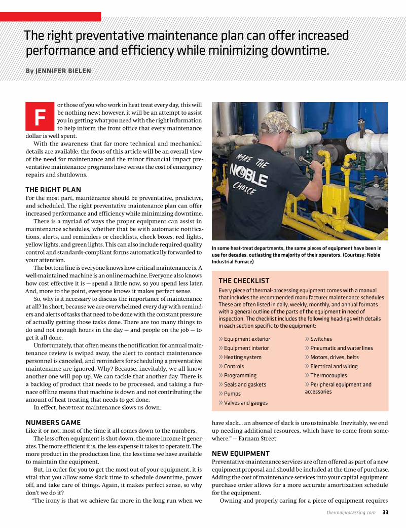
thermalprocessing.com 33
The right preventative maintenance plan can offer increased performance and efficiency while minimizing downtime.By JENNIFER BIELEN
or those of you who work in heat treat every day, this will be nothing new; however, it will be an attempt to assist you in getting what you need with the right information to help inform the front office that every maintenance
dollar is well spent.With the awareness that far more technical and mechanical
details are available, the focus of this article will be an overall view of the need for maintenance and the minor financial impact pre-ventative maintenance programs have versus the cost of emergency repairs and shutdowns.
THE RIGHT PLANFor the most part, maintenance should be preventative, predictive, and scheduled. The right preventative maintenance plan can offer increased performance and efficiency while minimizing downtime.
There is a myriad of ways the proper equipment can assist in maintenance schedules, whether that be with automatic notifica-tions, alerts, and reminders or checklists, check boxes, red lights, yellow lights, and green lights. This can also include required quality control and standards-compliant forms automatically forwarded to your attention.
The bottom line is everyone knows how critical maintenance is. A well-maintained machine is an online machine. Everyone also knows how cost effective it is — spend a little now, so you spend less later. And, more to the point, everyone knows it makes perfect sense.
So, why is it necessary to discuss the importance of maintenance at all? In short, because we are overwhelmed every day with remind-ers and alerts of tasks that need to be done with the constant pressure of actually getting those tasks done. There are too many things to do and not enough hours in the day — and people on the job — to get it all done.
Unfortunately, that often means the notification for annual main-tenance review is swiped away, the alert to contact maintenance personnel is canceled, and reminders for scheduling a preventative maintenance are ignored. Why? Because, inevitably, we all know another one will pop up. We can tackle that another day. There is a backlog of product that needs to be processed, and taking a fur-nace offline means that machine is down and not contributing the amount of heat treating that needs to get done.
In effect, heat-treat maintenance slows us down.
NUMBERS GAMELike it or not, most of the time it all comes down to the numbers.
The less often equipment is shut down, the more income it gener-ates. The more efficient it is, the less expense it takes to operate it. The more product in the production line, the less time we have available to maintain the equipment.
But, in order for you to get the most out of your equipment, it is vital that you allow some slack time to schedule downtime, power off, and take care of things. Again, it makes perfect sense, so why don’t we do it?
“The irony is that we achieve far more in the long run when we
have slack… an absence of slack is unsustainable. Inevitably, we end up needing additional resources, which have to come from some-where.” — Farnam Street
NEW EQUIPMENTPreventative-maintenance services are often offered as part of a new equipment proposal and should be included at the time of purchase. Adding the cost of maintenance services into your capital equipment purchase order allows for a more accurate amortization schedule for the equipment.
Owning and properly caring for a piece of equipment requires
F
In some heat-treat departments, the same pieces of equipment have been in use for decades, outlasting the majority of their operators. (Courtesy: Noble Industrial Furnace)
THE CHECKLISTEvery piece of thermal-processing equipment comes with a manual that includes the recommended manufacturer maintenance schedules. These are often listed in daily, weekly, monthly, and annual formats with a general outline of the parts of the equipment in need of inspection. The checklist includes the following headings with details in each section specific to the equipment:
» Equipment exterior
» Equipment interior
» Heating system
» Controls
» Programming
» Seals and gaskets
» Pumps
» Valves and gauges
» Switches
» Pneumatic and water lines
» Motors, drives, belts
» Electrical and wiring
» Thermocouples
» Peripheral equipment and accessories
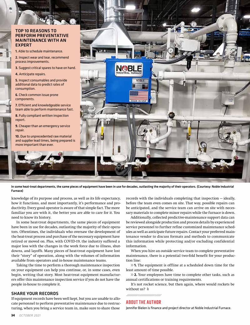
34 OCTOBER 2021
knowledge of its purpose and process, as well as its life expectancy, how it functions, and most importantly, it’s performance and pro-ductivity. Every good operator is aware of that simple fact. The more familiar you are with it, the better you are able to care for it. You need to know its history.
In some heat-treat departments, the same pieces of equipment have been in use for decades, outlasting the majority of their opera-tors. Oftentimes, the individuals who oversaw the development of the heat-treat process and purchase of the necessary equipment have retired or moved on. Plus, with COVID-19, the industry suffered a major loss with the changes in the work force due to illness, shut-downs, and layoffs. Many pieces of heat-treat equipment have lost their “story” of operation, along with the volumes of information available from operators and in-house maintenance teams.
Taking the time to perform a thorough maintenance inspection on your equipment can help you continue, or, in some cases, even begin, writing that story. Most heat-treat equipment manufactur-ers offer this maintenance inspection service if you do not have the people in-house to complete it.
SHARE YOUR RECORDSIf equipment records have been well kept, but you are unable to allo-cate personnel to perform preventative maintenance due to restruc-turing, when you bring a service team in, make sure to share those
records with the individuals completing that inspection — ideally, before the team even comes on site. That way, possible repairs can be anticipated, and the service team can arrive on site with neces-sary materials to complete minor repairs while the furnace is down.
Additionally, collected predictive-maintenance support data can be reviewed alongside production and process details by experienced service personnel to further refine customized maintenance sched-ules as well as anticipate future repairs. Contact your preferred main-tenance vendor to discuss formats and methods to communicate this information while protecting and/or excluding confidential information.
When you hire an outside service team to complete preventative maintenance, there is a potential two-fold benefit for your produc-tion line:
» 1. The equipment is offline at a scheduled down time for the least amount of time possible.
» 2. Your employees have time to complete other tasks, such as annual certifications or training requirements.
It’s not rocket science, but then again, where would rockets be without us?
ABOUT THE AUTHORJennifer Bielen is finance and project director at Noble Industrial Furnace.
In some heat-treat departments, the same pieces of equipment have been in use for decades, outlasting the majority of their operators. (Courtesy: Noble Industrial Furnace)
TOP 10 REASONS TO PERFORM PREVENTATIVE MAINTENANCE WITH AN EXPERT1. Able to schedule maintenance.
2. Inspect wear and tear, recommend process improvements.
3. Suggest critical spares to have on hand.
4. Anticipate repairs.
5. Inspect consumables and provide additional data to predict rates of consumption.
6. Check common issue prone components.
7. Efficient and knowledgeable service team able to perform maintenance fast.
8. Fully compliant written inspection report.
9. Cheaper than an emergency service repair.
10. Due to unprecedented raw material and supplier lead times, being prepared is more important than ever.

thermalprocessing.com 35
Annealing • Degassing • Creep Forming and Flattening • Stress Relieving • BrazingSolution Treat and Age (STA) • Homogenizing • Sintering • Hydriding/Dehydriding
• Bright, clean, scale-free surfaces with minimal distortion
• Furnace capacities up to 48 feet long and 150,000 lbs
• Full line of major aerospace approvals• Titanium and high nickel alloys
For more information or a quote, call 1-855-WE-HEAT-IT or visit solaratm.com
Advantages
Solar Atmospheres heat treated the titanium manifold weldment used on the Orion Launch Abort System.
Aerospace Vacuum Heat Treating ServicesAerospace Vacuum Heat Treating Services
Harness our leading-edge vacuum technology to help assure your flight-critical parts go the distance.
VACUUM PROCESSING Heat Treating • Brazing • Carburizing • NitridingEastern PA Western PA
California South Carolina
9001:20159100DAS
SA ThermProc Aerospace 2020 FPg.indd 1SA ThermProc Aerospace 2020 FPg.indd 1 9/8/2021 8:18:22 AM9/8/2021 8:18:22 AM

36 OCTOBER 2021
AC7102 CHECKLIST REVIEWPART 5
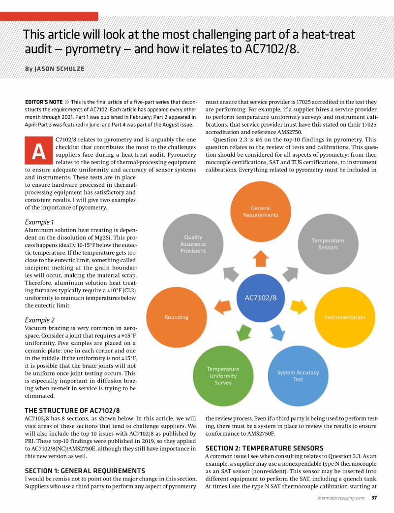
thermalprocessing.com 37
This article will look at the most challenging part of a heat-treat audit — pyrometry — and how it relates to AC7102/8. By JASON SCHULZE
EDITOR’S NOTE » This is the final article of a five-part series that decon-structs the requirements of AC7102. Each article has appeared every other month through 2021. Part 1 was published in February; Part 2 appeared in April; Part 3 was featured in June; and Part 4 was part of the August issue.
C7102/8 relates to pyrometry and is arguably the one checklist that contributes the most to the challenges suppliers face during a heat-treat audit. Pyrometry relates to the testing of thermal-processing equipment
to ensure adequate uniformity and accuracy of sensor systems and instruments. These tests are in place to ensure hardware processed in thermal-processing equipment has satisfactory and consistent results. I will give two examples of the importance of pyrometry.
Example 1Aluminum solution heat treating is depen-dent on the dissolution of Mg2Si. This pro-cess happens ideally 10-15°F below the eutec-tic temperature. If the temperature gets too close to the eutectic limit, something called incipient melting at the grain boundar-ies will occur, making the material scrap. Therefore, aluminum solution heat treat-ing furnaces typically require a ±10°F (CL2) uniformity to maintain temperatures below the eutectic limit.
Example 2Vacuum brazing is very common in aero-space. Consider a joint that requires a ±15°F uniformity. Five samples are placed on a ceramic plate: one in each corner and one in the middle. If the uniformity is not ±15°F, it is possible that the braze joints will not be uniform once joint testing occurs. This is especially important in diffusion braz-ing when re-melt in service is trying to be eliminated.
THE STRUCTURE OF AC7102/8AC7102/8 has 8 sections, as shown below. In this article, we will visit areas of these sections that tend to challenge suppliers. We will also include the top-10 issues with AC7102/8 as published by PRI. These top-10 findings were published in 2019, so they applied to AC7102/8(NC)/AMS2750E, although they still have importance in this new version as well.
SECTION 1: GENERAL REQUIREMENTSI would be remiss not to point out the major change in this section. Suppliers who use a third party to perform any aspect of pyrometry
must ensure that service provider is 17025 accredited in the test they are performing. For example, if a supplier hires a service provider to perform temperature uniformity surveys and instrument cali-brations, that service provider must have this stated on their 17025 accreditation and reference AMS2750.
Question 2.3 is #6 on the top-10 findings in pyrometry. This question relates to the review of tests and calibrations. This ques-tion should be considered for all aspects of pyrometry: from ther-mocouple certifications, SAT and TUS certifications, to instrument calibrations. Everything related to pyrometry must be included in
the review process. Even if a third party is being used to perform test-ing, there must be a system in place to review the results to ensure conformance to AMS2750F.
SECTION 2: TEMPERATURE SENSORSA common issue I see when consulting relates to Question 3.3. As an example, a supplier may use a nonexpendable type N thermocouple as an SAT sensor (nonresident). This sensor may be inserted into different equipment to perform the SAT, including a quench tank. At times I see the type N SAT thermocouple calibration starting at
A

38 OCTOBER 2021
100°F, which would mean it is not calibrated in the range of the quench tank.
Question 3.7 seems to be a common challenge and has been for as long as I have been exposed to AMS2750 (since Revision C). This relates to the depth of insertion for Types E and K thermocouples used above 500°F. To start, this should be stated within suppliers’ internal procedures. Also, this must be controlled somehow at the furnace. I have seen several ways this is accomplished, usually by mechanical means. The requirement essentially states that, the portion of the thermocouple exposed to heat within the thermal-processing equipment must remain in that position and/or more of the thermocouple not previously exposed to heat may be inserted. The point is, portions of the thermocouple exposed to heat cannot be retracted from the work zone.
A frequent question I receive is how often suppliers need to replace their furnace thermocouples (i.e. control, overtemperature, etc.). With regards to AMS2750F, it is up to the supplier to come up with a replacement frequency and justify that frequency with SAT, TUS or instrument calibration data. Keep in mind, prime and indus-try specifications may over-ride this allowance and specify specific frequencies. Also, if the SAT waiver is implemented at a supplier, then there is a specific control thermocouple replacement frequency.
A new requirement is Question 3.14. It relates to how hot junc-tions are made. The hot junction is the point where the dissimilar wires touch to create the mV which converts to temperature. This can be made by either twisting or welding, or a combination of the two, as long as no filler metal is used.
SECTION 3: INSTRUMENTATIONThe first major change in this section is that all process instruments must be digital after June 30, 2022. This would include pro-cess recording systems, controlling systems, and overtemperature controls. Also, record-ing systems must now have a readability to the 10th of a degree (0.1°F). So far, I haven’t seen this being a major issue for suppliers to conform to.
Question 4.2.3 requires that each thermo-couple type and input/output being used be calibrated. I often see a type or input/output not calibrated when reviewing certifications. It is incumbent on suppliers to realize what thermocouple types must be calibrated and if they need both input and output for all types.
Questions 4.2.4 (test instruments) and 4.3.2.4 (furnace instru-ments) seems to cause some confusion at times. This question requires you calibrate each channel altered individually or as a group. An example of this is a Yokogawa DX model. The manual for this recorder states that, to calibrate, you insert into channel 2, and this will calibrate channels 1-10 (or 1-12, depending on the model) because they are on a single board. Other recorder manuals may state each channel needs to be calibrated individually. It is up to the supplier to read the manual and calibrate accordingly.
Calibration of each sensor system that qualifies the instrumenta-tion type may seem straightforward, although at times I have noticed it is not for some suppliers. Question 4.3.2 describes this. Let’s look at an example of a type D instrumentation where a load thermocouple is used from time to time. In this case, it is not only what qualifies the instrumentation type, but what is also used as product acceptance, the load thermocouple. In this case, the load thermocouple system
would need to be calibrated as well. Question 4.3.3 has been modified to reflect a change in AMS2750F.
Sensitivity is only required for analog instruments, not digital instruments.
Within the top-10 findings, the question regarding stickers and calibration records is No. 1. This is a broad statement as it is not specific regarding what precisely was missing, although we can still use this to our benefit. Questions 4.3.4 through 4.3.4.5 state what is required on the calibration sticker, with 4.3.4.1 being a new require-ment to revision F. Question 4.3.5.1 through 4.3.5.19 state what is required on the instrument calibration certification. To ensure a sup-plier has all of the required information, it would be a good idea for suppliers to document these items within their internal procedures and include them within the quality verification.
SECTION 4 – SYSTEM ACCURACY TESTINGQuestion 5.3.3 requires that SATs are performed the same way each time. In other words, once the initial SAT position and depth of insertion is established on the initial SAT, it must be repeated each subsequent time. The common issue I see in this situation is the specifics are not documented within suppliers’ internal procedure. This will potentially cause technicians/operators to set up the SAT test thermocouple in the incorrect location.
An additional frequent finding is Question 5.3.5. This question requires that SATs are performed on the sensor systems qualifying the equipment’s instrumentation type as well as addition systems used as product acceptance. An example of this may be a supplier des-ignated the equipment as Type D although load thermocouples are used periodically when required and are part of product acceptance. This means the load thermocouple(s) used would require an SAT.
Question 5.3.5.3 requires additional systems used to justify the SAT interval extension must have an SAT performed. An example of this may be that two Type N thermocouples are installed — one
Pyrometry is arguably the most challenging part of a heat-treat audit.

thermalprocessing.com 39
attached to the control and one attached to the overtemperature device. Since the overtemperature device is being used to justify the SAT frequency extension, the over temperature would then require an SAT. At times, this required is overlooked when implementing the SAT interval extension.
Question 5.5 covers the alternate SAT requirements. This section was initially confusing for some suppliers as it may have been difficult to interpret the requirements of the alternate SAT. By now, most sup-pliers who must conform to this section are aware of what is required. The challenge may be with regards to the new requirements for docu-mentation of the alternate SAT. If the alternate SAT is required, it is important to recognize the new documentation requirements and ensure the required documentation details are in place.
SECTION 5: TEMPERATURE UNIFORMITY SURVEYSThe initial challenge suppliers may face with AMS2750F is the extend-ed frequency. Tables 18 and 19 in AMS2750F have a slight wording change regarding the quantity of successful TUSs that must be achieved before moving the extended frequency. As an example, if a supplier is a CL2 Type D, TUSs must be performed monthly for four consecutive successful tests, then the supplier could extend it to bimonthly. When working to revision E, a supplier could count the initial survey as 1 of 4. With the slight rewording in revision F, this is no longer possible. The initial survey no longer counts toward the required consecutive successful TUSs. Through my recent consult-ing, I have noticed this to be an issue for those working to AMS2750F.
Another challenge I see when suppliers are working to AMS2750F relates to Question 6.1.5. This question requires vacuum furnaces using partial pressure must have one periodic TUS performed annu-ally using partial pressure in the range used with one of the partial
pressure gasses. While this is a new requirement to revision F, I am noticing this requirement being missed on recent audits.
Question 6.2.5 requires suppliers have a detailed diagram show-ing the location of the furnace and test thermocouples. I notice, from time to time, the diagram either within internal procedures or on the TUS certification do not show the location (or the correct loca-tion) of the control thermocouple. It is important to determine the location of the furnace thermocouples and identify them correctly on the TUS certification and any other location (i.e. procedures) a diagram may be located.
SUMMARYPyrometry is arguably the most challenging part of a heat-treat audit. The most successful approach to understanding pyrometry is to receive continuous training and hands on practice to become familiar. There are many training programs available to suppliers. Using these tools will enable suppliers to successfully implement and maintain conformance to AMS2750F. This is the last in a series of articles covering select Nadcap checklists. I hope it has been help-ful to readers.
ABOUT THE AUTHORJason Schulze is the director of technical services at Conrad Kacsik Instrument Systems, Inc. As a metallurgical engineer with 20-plus years in aerospace, he assists potential and existing Nadcap suppliers in conformance as well as metallurgical consulting. He is contracted by PRI Training as a Lead Instructor to teach multiple PRI courses, including pyrometry, RCCA, and Checklists Review for heat treat. Jason is also a voting member on two AMEC committees. Contact him at [email protected]. More info: www.kacsik.com.
GET CONNECTEDThermalProcessing.com is your trusted online source
for information and technical knowledge about the heat treating industry.
You’ll find topical articles, company profiles and interviews with industry insiders, and timely heat treat industry news.
Get your FREE subscription, plus our online content, at www.thermalprocessing.com

40 OCTOBER 2021
SUPPLYING WELDING WIRE FOR THE REPAIR OF FORGING TOOLS
COMPANY PROFILE /// COR-MET INC.
Flood welding RIG wire welding stick. (Courtesy: COR-MET)

thermalprocessing.com 41
COR-MET manufactures a wide selection of cored welding wire made of alloy steels to nickel and cobalt-base alloys available for resistance to high temperatures, abrasion, and impacts. By KENNETH CARTER, Thermal Processing editor
t’s important that forging dies and tools used for large presses and hammers are in prime operating condition. But when they’re not, the next step is often to get the tools weld repaired.
The job of ensuring the best weld possible falls to COR-MET, a company that manufactures flux cored wire, TIG rods, and stick elec-trodes for the forging industry. The company products are designed for weld repair of closed dies, open dies, trim tools, rams, sow blocks, bolsters, and columns. Specialty welding products include flux cored gas-shielded wire, sub-arc wire, stick electrodes, and metal core wire used in robotic applications.
COR-MET manufactures weld wire to improve high temperature and abrasive wear and crack resistance for forge tooling. The weld repair process will include a lower cost 4340 or similar die steel and add an H-12 tool steel weld to the working surface for heat and wear resistance. A basic hard-surfacing operation to improve the number of forged parts compared to the tooling cost.
FORGE SHOPS, STEEL MILLS, AND FOUNDRIESAlthough COR-MET doesn’t often deal directly with the heat-treat industry, the company’s welding wire is used to repair forging dies and tools that will be sent to a heat treater for nitriding or stress relieving, according to Sales Manager Scott Frasso. Most iron-base weld wire used for die repair will need to be tempered to the desired HRc hardness. A steel mill roll welded with a 420 stainless steel overlay will need to be stress relieved. In addition, a foundry casting made of 4130 will need a similar matching weld wire alloy to heat treat the same as the base metal.
Also, a nickel-base welding wire is used for the manufacturing of high-temperature furnace rolls. This would be alloys, similar to Hastelloy X, that maintain strength, duc-tility, and oxidation resistance at service temperatures up to 1,800°F for extended periods.
The welding wire that Frasso detailed can be used in a variety of repair scenarios.
“Tools needing repair would be consid-ered metal-to-metal wear applications,” he said. “Some of them are hammers where they’re actually pounding a shape into a steel ingot, or they’re a press application where it’s a little quieter, one slow press, rather than a multiple hammer operation. There are different types of open dies. Some of them are large flat dies. Some of them are ring roller cones that manufacture rings for wind and aerospace applications,
and those all need to be weld-repaired. On top of that, they need to repair trimming tools and punches to go along with those parts. Those are the types of products that we manufacture welding wire for at COR-MET INC.”
ENSURING THE LIFE OF THE PRODUCTA good weld is important to the life of a product, according to Frasso.
“What does it cost to prep, preheat, weld, temper, and machine dies and tools for Forge Shop?” he said. “Welding wire is a big part of this cost. A simple example would be if the tooling cost is $200,000 and you produce 1,000 forged parts, your cost per part is $200. If you forge 2,000 parts, your cost for just the tooling drops by half.”
In addition to the products COR-MET provides, the company also offers other services as well, according to Frasso.
“We provide some welder training,” he said. “We provide R&D work. And we also manufacture some semi-automatic equipment that’s designed to keep the welder, the worker, away from the heat and the smoke while he’s welding.”
A recent addition to COR-MET’s product line is manufacturing weld wire for robotic applications, according to Frasso.
“The Robot product line includes wires for metal-to-metal wear, impacts, and buildup applications,” he said. “The weld wire is a metal core slag free 1/16” diameter wire packaged by a 250-pound drum.”
ADDRESSING CUSTOMER NEEDS QUICKLYBeing a small company allows COR-MET to move quickly when it comes to its customers’ needs, according to Frasso.
“One of the things that always stands out to me about COR-MET — and I use it as a sales tool — is we’re a small company, so we’re able to move quickly,” he said. “In many cases, when a customer says, ‘Hey, I need a new product, a new chemistry, or can you tweak an existing wire chemistry with alloy additions?’ We can decide to make it, manu-facture it, and have it out the door before a larger company could decide whether or not they can even make it. That’s basically how we’ve operated here: Find a need, and we manufacture a product.”
“COR-MET manufactures weld wire to match your base metal chemistry,” Frasso said. “This is most often requested for pro-prietary chemistries and not a commercially available welding wire, electrode, or TIG rod. This may be valuable to a foundry when the casting and the welding consumable needs to heat-treat to the same, or you need a good
I
Crankshaft die welded with a robot. (Courtesy: COR-MET)

42 OCTOBER 2021
color match. We have found special manufacture weld wire needs for stainless steel and nickel-base alloys.”
This means hitting challenges head on, according to Frasso.“The COR-MET engineering team builds and/or re-manufactures
equipment and develops new procedures to respond to any chal-lenge,” he said. “Recently, COR-MET has developed a complete metal-to-metal wear and impact resistant iron-base metal core wire product line for robotic welding of forging dies and additive manufacturing requirements.”
FOUNDED IN 1972That is much of the core reason COR-MET has chosen to remain small throughout its almost 50-year history, when Peter Kiilunen started the company in 1972 manufacturing flux cored wire, according to Frasso.
“Many companies were already manufacturing mild steel flux cored wire/ fabrication wires in the 1950s,” Frasso said. “COR-MET started manufacturing high-alloy flux cored wires in stainless steel, nickel, cobalt, maintenance wires, tool steels, and alloys to be used in forge die repair in modifications of 4340, H-12, 410NiMo, and 420 grade steels, as well as hard surfacing chrome carbides and manga-nese cored wire.”
And today COR-MET is still manufacturing higher alloys, wires, and electrodes, including No 7018 or 71 T-1 mild steel weld wire in the company’s product mix.
TRADE SHOW OFFERINGSAt the recent FabTech 2021 tradeshow in Chicago, Illinois, COR-MET highlighted its new line of QWP Flux Coated TIG wire that is designed to eliminate the need for gas purging and backing for TIG pipe welding, according to Frasso.
“The QWP Flux Coated TIG rod forms a slag on the backside of the pipe protecting the weld from oxidation (sugaring), he said. “Other new alloys this year are B3 and B91 used in high-temperature appli-cations. Standard alloys are 308H, 308L, 309L, 316L, 317L, 347, 16-8-2, 2209, 625, 82, plus B2, B6, and B8.”
Later this year, COR-MET is planning to exhibit at the Forge Fair 2021 in Detroit, Michigan, October 26-28, 2021.
MORE INFO www.cor-met.com
Flat die machined ready for welding. (Courtesy: COR-MET)
COR-MET manufactures weld wire to improve high temperature and abrasive wear and crack resistance for forge tooling. (Courtesy: COR-MET)

thermalprocessing.com 43
Thermal Processing wants to make sure the best possible audience knows your company. Through our print, online, and social media presence, our experienced staff can get your message to an industry that wants to know what you can do.
YOU’VE GOT THE PRODUCTS.YOU’VE GOT THE SERVICES.NOW, LET US SHARE YOUR STORY.
To learn more, contact national sales director Dave Gomez at [email protected] or call 800.366.2185 ext. 207
44 OCTOBER 2021
MARKETPLACE ///
Manufacturing excellence through quality, integration, materials, maintenance, education, and speed.
Contact Thermal Processing at 800-366-2185 to feature your business in the Marketplace.
YOUR THERMAL HEATING EXPERT
315-623-2124 315-623-2206
www.charlesahones.com
Charles A. Hones, Inc. is a recognized industry leader with over 100 years of expertise in thermal, heating and combustion engineering. We specialize in the production and restoration of melting furnaces, heat treating products, and industrial gas burners.
Used Heat Treating Furnaces and Ovens
Web: whkay.comEmail: [email protected]
Phone: 440-519-3800
Over 200 ovens and furnaces in stock
Cleveland, Ohio
Since 1936
CAN-ENG Furnaces International Limited specializes in the design of unique, high-volume batch and continuous industrial furnace systems for today’s and tomorrow’s demanding applications.
Propelling industry toward tomorrow’s opportunities, whether for Automotive, Aerospace, Steel, Military, or Oil and Gas applications, CAN-ENG has the experience and expertise to enable your success.
P.O. Box 235, Niagara Falls, New York 14302-0235 | T. 905.356.1327 | F. 905.356.1817
CAN-ENG FURNACES ENGINEERING SOLUTIONS TO LAST
CUSTOM SYSTEMS FOR CUSTOM PRODUCTS
To explore how CAN-ENG’s custom
systems can help with your individual needs,
visit us online www.can-eng.com
or email [email protected].
Precision Pyrolysis &Debinding Furnacesfor Ceramic Matrix
Composites & AdditiveManufacturing
XLC2448 set up for Pyrolysis with Multizone Heating Banks, Inert Atmosphere, and Rapid Cooling
F U R N A C E C O , I N C
If you have high-value loads to process, look no further than L&L Special Furnace. Our furnaces are the most reliable on the market – at any price! Each one is Special!
• Precision• Uniformity• Value
L&L CAN MEET THE STRICTEST PROVISIONS OFAMS2750E FOR AEROSPACE APPLICATIONS
20 Kent Road Aston, PA 19014 Phone: 877.846.7628 www.llfurnace.com

thermalprocessing.com 45
THERMAL PROCESSING SYSTEMS
YOUR SOURCEFOR COMPLIANCEWITH CQI-94TH EDITION
www.gasbarre .com
ISO 17025
RELIABILITY, EXPERTISE,
SERVICE, AND SELECTION
Let the experts at Gasbarre design and implement a CQI-9 Compliance Plan for you!
NEW REQUIREMENTS:n Digital instrumentationn Temperature recording for each control zonen Quarterly calibration of atmosphere controllersn Recording instruments for temperature controlling devices and protective atmosphere monitoringn Continuous temperature recording with an alarm systemn Continuous atmosphere recording with an alarm systemn Recording of cooling water temperaturen For sintering hardening, fan alarming and fan speed verificationn Continuous monitoring of furnace atmosphere, automatically controlled, and documented
BASIC AND ADVANCED PACKAGES AVAILABLEFeaturing enhanced support andconvenience options
•Lessthan2%VOCcontent•Non-flammable,noHazmat shippingregulations•Excellentone-coatcoverage•Stop-offprotectionup to.080”casedepths•Economicalternativeto foreign-madebrands
Vacuum Research Corp. • 100 Chapel Harbor Drive, #4Pittsburgh, PA 15238 USA • www.vacuumresearch.com800-426-9340 • email: [email protected]
©2021 Vacuum Research Corp.
High Vacuum ValvesElectric Motor Actuators
All VRC Motor Actuators Provide Open/Close, Throttle, and Soft Start Using Your Existing PLC
with 0 to 10 VDC or 4-20 mA Output.
If you want to optimize fl ow rates, minimize pressure drop, and reduce energy costs of your system, then this is the most vital piece of news you will read today.
Vacuum Gate Valves with Electric Motor Actuators from Vacuum Research, avoid premature repairs, increase system reliability, and eliminate performance gaps.
All our valves are (RoHS) 2015/863/EU compliant. To increase your system’s effi ciency today, call 800-426-9340 for a quote or email [email protected].
METHOD 1, 2, 3 CURRENTLY IN STANDARD USEMethod 1 – Remove load from furnace and lower furnace temperature.
Method 2 – Remove atmosphere and add small amount of air to furnace for 8 hours or more.
Method 3 – Use a wand to direct air to heavy carbon deposits.
Method 4 – Unnecessary to remove load or atmosphere from furnace. Do not lower furnace temperature. Carburize load until finished with CH4 (soot) under control with Method 4.
AFTER LOAD IS REMOVED, METHOD 4 WILL CLEAN THE FURNACE
Contact [email protected]
SOOT CONTROLLED CARBURIZING – METHOD 4
HEAVY CARBON CO. ENDOCARB
46 OCTOBER 2021
[email protected] • noblefurnace.com
GAS, ELECTRIC | BOX, BELL, PIT, BELT, CAR BOTTOM, TUBEALL PROCESSES | SPECIALIZING IN VPA, VPC COATINGS
On-site repairs & maintenance – troubleshooting – burner tuning dismantling & relocation services
Designing & manufacturing custom industrial furnaces for over 45 years
HOW IT STARTED HOW IT IS NOW
Service, consumables and critical spares for all brands of equipment
800-956-4437 + www.dataloggerinc.com
We offer through process, temperature logging, and paperless recorders for oven and furnace monitoring
DATA LOGGERS FOR ALL APPLICATIONS
Connect your company to the heat treating industry with a storefront in the Thermal Processing Community. Storefronts paint a portrait of your company with a 500-word description and include your logo, website link, phone number, email addresses, and videos.
JOIN THE THERMAL PROCESSING
FOR ONLYCOMMUNITY
$350PER YEAR
For information on how you can participate in the ThermalProcessing.com community storefront, contact [email protected].
Dave Gomez national sales manager 800.366.2185 ext. 207
MAXIMIZE YOUR EXPOSURE

thermalprocessing.com 47
ADVERTISER INDEX ///
COMPANY NAME PAGE NO.
Applied Test Systems ......................................................................... 11
Avion Manufacturing ......................................................................... 45
Can-Eng ..............................................................................................44
CAS DataLoggers ...............................................................................46
Charles A. Hones, Inc. .........................................................................44
Cor-Met ................................................................................................. 9
DMP CryoSystems .............................................................................. 47
Gasbarre Thermal Processing Systems ............................................. 45
Graphite Metallizing Corporation (Graphalloy) .................................. 11
Heavy Carbon Company ..................................................................... 45
Lindberg/MPH ...................................................................................... 3
Linde ...................................................................................................BC
L&L Special Furnace Co. Inc. ..............................................................44
MadgeTech .............................................................................................7
Noble Industrial Furnace ....................................................................46
Optris ...................................................................................................13
Pelican Wire .......................................................................................IBC
Premier Furnace Specialists, Inc. ...................................................... IFC
Solar Atmospheres ............................................................................. 29
Solar Manufacturing ...........................................................................15
The Duffy Company ...........................................................................48
Thermal Product Solutions ................................................................46
Thermcraft ...........................................................................................14
Vacuum Research Corp. ..................................................................... 45
W.H. Kay Company .............................................................................44
Wisconsin Oven .................................................................................... 5
For more information visit www.cryosystems.com
MULTIPLE
TEMPERS.
ONE CYCLE.
C R Y O F U R N A C E | C R Y O T E M P E R | C R Y O F R E E Z E R
-300°+1200°F to
1 DATA REPORT1 DATA REPORT1 DATA REPORT
99% UPTIME99% UPTIME99% UPTIME

48 OCTOBER 2021
Q& A /// INTERVIEW WITH AN INDUSTRY INSIDER
What does Metallurgical High Vacuum Corporation do for the industry?We remanufacture pumps. That’s probably the core of our business, but that’s changing because of what’s happened over the last two years. Our customers are coming to us with a wide variety of service ques-tions, and we’re troubleshooting entire systems now, not just pumps.
In addition to that, customers have asked us to start designing equipment that we hadn’t designed before, which are related to the heat-treat business. For instance, one example is we’re being asked to design a furnace door and then manufacture it for this customer. Another example is we designed and manufactured a rotary feed test stand. The customer called us and said, “You are repairing our vacuum equipment. Can you design this?” We looked at it and said,
“Yes. We’ve got the engineering expertise. We’ll do it.” We designed it and manufactured it in eight weeks. So, we’ve become much more diverse in what we do. It is a more turnkey approach.
What steps need to be taken in order to analyze and restore pumping equipment to OEM specifications and tolerances? What do you do to make that happen?In our particular case, first it’s the analysis. We will tear a pump down, take all the measurements and compare them to what the OEM specifications are. If it requires replacing a worn part, we’ll purchase and install or manufacture it. We machine other parts onsite that can be returned to OEM specs to make sure everything is exactly to those specifications. By not outsourcing our machining, we control quality. But we don’t stop there.
Our testing is rigorous and validates the pump will perform when installed. A standard test is to run the pump for 20 hours. But that simply tells you that the pump runs. It doesn’t tell you how well it functions in the process. We have a test stand, which we constructed with PLC controls, that has the capability to draw the pump down to process required levels. It is measured against the performance to the published curves of when that pump came off the assembly line. It has to match up, or we go back in and determine what has to be done.
Your onsite services include predictive maintenance and preventive maintenance. What’s the difference between them?Predictive maintenance is being able to determine ahead of time,
“This equipment will approach failure in this number of hours.” Preventive maintenance is maintaining the equipment and extend-ing its life-cycle as long as possible. That’s how to distinguish between the two terms. We just recently had a customer who came to us and asked, “What can we do so that we don’t have process interruptions? These pumps are unreliable and failing frequently.” We developed a monitoring program that included testing the pump oil at regular
intervals. Oil cleanliness has a direct bearing on pump failure in many cases — especially in liquid ring pumps. Every month we’ll sample the oil on that particular series of pumps and determine the solids content. When it gets to a point where oil needs to be changed, that’s the point where we now have set the preventive maintenance schedule. We’ve also taken that a step further and looked at one of our customers, who is cutting edge. Vibration analysis has been performed, and a baseline has been established. We worked together and devel-oped a run time setpoint for the pumps. In a certain number of hours, each pump is pulled before it goes to failure. Because this procedure has been established, the re-manufacture cost is substantially reduced.
You’re able to reverse engineer obsolete parts. How do you approach a customer when they bring you that challenge?We’ll review the economics. If he’s a large customer and has a pump that is obsolete, which he does not want to replace, we will reverse engineer and produce it. If it’s a machined part, we’ll make a CAD drawingproperly toleranced with material and heat-treatment call-outs as needed. If it’s a casting, we’ll make a CAD drawing and get a foundry to quote on patterns and the casting. And then we machine it. We’ve got four CNC Mazaks, and we’ll turn the obsolete part into an exact replica. That engineering is how we’ve propelled ourselves into the newer field of designing things that are related to the pump systems but not part of the pump system.
Where do you see the industry in the next decade and your place in that future?Most industries have had a hiccup, but especially in aerospace. But currently, that industry is rebounding nicely. Our place in that future is to assist customers with improving their systems, reduc-ing equipment costs and maximizing production time.
What types of aerospace projects do you work on? We work with the subcontractors, who are the companies that make jet engines, turbine blades — all of the vacuum heat-treat processes. This includes the titanium and aluminum processed parts that are assemblies in commercial and military aircraft.
Anything else you’d like to mention?Heat treating is a stable business. Our service business was 5 percent of our gross revenue, but with the shift in demand, we are now growing at 20 to 25 percent in that sector. And that’s not just standard preven-tive maintenance, that’s heavy trouble shooting of entire systems.
MORE INFO www.methivac.com
“Customers have asked us to address complete vacuum systems in the heat-treat industry.”
JEFF MARSHALL /// VP AND GENER AL MANAGER /// ME TALLURGICAL HIGH VACUUM CORP


Making our world more productive
The Linde logo and the Linde wordmark are trademarks or registered trademarks of Linde plc or its affiliates. Copyright © 2021, Linde plc. 6/2021 P-40-4700-7
Linde offers atmosphere gases, purging and inerting process gases (hydrogen, nitrogen, carbon dioxide, argon, helium), plus services including thermal spray coating, integrated gas supply capability, and on-site system evaluation, design, testing, and installation. Let us help improve your heat-treating process.
Visit www.lindeus.com/heattreating or call 1.844.44LINDE to find out more.
Turn up the heat on your successWith gases and services from Linde
Ask about the
benefits of Argon!