issue 2.1 esa s/95/088/972 - nasa · esa s/95/088/972. con ten ts ... sop science op erations plan...
TRANSCRIPT

SOHO
Science Operations Plan
Issue 2.1
March 1995
ESA S/95/088/972


Contents
Preface : : : : : : : : : : : : : : : : : : : : : : : : : : : : : : : : : : : : : : : : : : : : : : : 2Reference Documents : : : : : : : : : : : : : : : : : : : : : : : : : : : : : : : : : : : : : : : 2List of Acronyms : : : : : : : : : : : : : : : : : : : : : : : : : : : : : : : : : : : : : : : : : : 3List of Figures : : : : : : : : : : : : : : : : : : : : : : : : : : : : : : : : : : : : : : : : : : : 5List of Tables : : : : : : : : : : : : : : : : : : : : : : : : : : : : : : : : : : : : : : : : : : : : 6
1 Mission Overview 7
1.1 Scienti�c objectives : : : : : : : : : : : : : : : : : : : : : : : : : : : : : : : : : : : : : : 71.2 Instrumentation : : : : : : : : : : : : : : : : : : : : : : : : : : : : : : : : : : : : : : : : 81.3 Spacecraft, Orbit, Attitude : : : : : : : : : : : : : : : : : : : : : : : : : : : : : : : : : 91.4 Operations : : : : : : : : : : : : : : : : : : : : : : : : : : : : : : : : : : : : : : : : : : 10
2 SOHO Operations Policy and Requirements 12
2.1 Operations Plan : : : : : : : : : : : : : : : : : : : : : : : : : : : : : : : : : : : : : : : 122.1.1 Overview : : : : : : : : : : : : : : : : : : : : : : : : : : : : : : : : : : : : : : : 12
2.1.1.1 Routine operation : : : : : : : : : : : : : : : : : : : : : : : : : : : : : 122.1.1.2 Responsibilities : : : : : : : : : : : : : : : : : : : : : : : : : : : : : : : 12
2.1.2 Monthly planning cycle : : : : : : : : : : : : : : : : : : : : : : : : : : : : : : : 132.1.3 Weekly detailed planning : : : : : : : : : : : : : : : : : : : : : : : : : : : : : : 142.1.4 Daily optimisation meeting : : : : : : : : : : : : : : : : : : : : : : : : : : : : : 142.1.5 S/C operations time line : : : : : : : : : : : : : : : : : : : : : : : : : : : : : : : 15
2.1.6 Commanding schedule : : : : : : : : : : : : : : : : : : : : : : : : : : : : : : : : 152.1.7 Instruments timeline: sample : : : : : : : : : : : : : : : : : : : : : : : : : : : : 152.1.8 Coordinated campaigns : : : : : : : : : : : : : : : : : : : : : : : : : : : : : : : 18
2.2 Conventions : : : : : : : : : : : : : : : : : : : : : : : : : : : : : : : : : : : : : : : : : : 192.2.1 Spacecraft time : : : : : : : : : : : : : : : : : : : : : : : : : : : : : : : : : : : : 192.2.2 Ground time : : : : : : : : : : : : : : : : : : : : : : : : : : : : : : : : : : : : : 20
2.2.3 Solar rotation axis : : : : : : : : : : : : : : : : : : : : : : : : : : : : : : : : : : 202.2.4 Inter-instrument ag reference coordinates : : : : : : : : : : : : : : : : : : : : : 202.2.5 Spacecraft orbit coordinates : : : : : : : : : : : : : : : : : : : : : : : : : : : : : 21
2.3 Inter-instrument ags : : : : : : : : : : : : : : : : : : : : : : : : : : : : : : : : : : : : 21
3 Data 23
3.1 Data sets : : : : : : : : : : : : : : : : : : : : : : : : : : : : : : : : : : : : : : : : : : : 23
3.1.1 Science data : : : : : : : : : : : : : : : : : : : : : : : : : : : : : : : : : : : : : 233.1.2 Housekeeping data : : : : : : : : : : : : : : : : : : : : : : : : : : : : : : : : : : 233.1.3 Ancillary data : : : : : : : : : : : : : : : : : : : : : : : : : : : : : : : : : : : : 233.1.4 Summary data : : : : : : : : : : : : : : : : : : : : : : : : : : : : : : : : : : : : 243.1.5 Processed science data : : : : : : : : : : : : : : : : : : : : : : : : : : : : : : : : 26
1

2 CONTENTS
3.1.6 Synoptic information and predictive information : : : : : : : : : : : : : : : : : 263.2 Dissemination and archiving : : : : : : : : : : : : : : : : : : : : : : : : : : : : : : : : : 27
3.2.1 Data availability : : : : : : : : : : : : : : : : : : : : : : : : : : : : : : : : : : : 273.2.2 Data Distribution Facility : : : : : : : : : : : : : : : : : : : : : : : : : : : : : : 293.2.3 EOF : : : : : : : : : : : : : : : : : : : : : : : : : : : : : : : : : : : : : : : : : : 293.2.4 Databases : : : : : : : : : : : : : : : : : : : : : : : : : : : : : : : : : : : : : : : 29
3.3 Standard formats : : : : : : : : : : : : : : : : : : : : : : : : : : : : : : : : : : : : : : : 303.3.1 Overview : : : : : : : : : : : : : : : : : : : : : : : : : : : : : : : : : : : : : : : 303.3.2 SFDU : : : : : : : : : : : : : : : : : : : : : : : : : : : : : : : : : : : : : : : : : 303.3.3 PVL : : : : : : : : : : : : : : : : : : : : : : : : : : : : : : : : : : : : : : : : : : 313.3.4 FITS : : : : : : : : : : : : : : : : : : : : : : : : : : : : : : : : : : : : : : : : : : 31
3.3.4.1 Primary FITS �les : : : : : : : : : : : : : : : : : : : : : : : : : : : : : 323.3.4.2 ASCII tables : : : : : : : : : : : : : : : : : : : : : : : : : : : : : : : : 323.3.4.3 Binary tables : : : : : : : : : : : : : : : : : : : : : : : : : : : : : : : : 323.3.4.4 The IMAGE extension : : : : : : : : : : : : : : : : : : : : : : : : : : 33
3.3.5 CDF : : : : : : : : : : : : : : : : : : : : : : : : : : : : : : : : : : : : : : : : : : 333.4 Use of SOHO data | data rights : : : : : : : : : : : : : : : : : : : : : : : : : : : : : : 34
3.4.1 Introduction : : : : : : : : : : : : : : : : : : : : : : : : : : : : : : : : : : : : : 343.4.2 De�nitions : : : : : : : : : : : : : : : : : : : : : : : : : : : : : : : : : : : : : : 34
3.4.2.1 Data access rights : : : : : : : : : : : : : : : : : : : : : : : : : : : : : 343.4.2.2 SOHO science projects : : : : : : : : : : : : : : : : : : : : : : : : : : 343.4.2.3 Responsibilities : : : : : : : : : : : : : : : : : : : : : : : : : : : : : : : 353.4.2.4 Data levels : : : : : : : : : : : : : : : : : : : : : : : : : : : : : : : : : 35
3.4.3 SOHO science data access policy : : : : : : : : : : : : : : : : : : : : : : : : : : 363.4.4 Archiving : : : : : : : : : : : : : : : : : : : : : : : : : : : : : : : : : : : : : : : 363.4.5 Guest Investigators : : : : : : : : : : : : : : : : : : : : : : : : : : : : : : : : : : 36
3.4.5.1 General : : : : : : : : : : : : : : : : : : : : : : : : : : : : : : : : : : : 363.4.5.2 Nature of participation : : : : : : : : : : : : : : : : : : : : : : : : : : 363.4.5.3 Mechanics of selection : : : : : : : : : : : : : : : : : : : : : : : : : : : 373.4.5.4 Implementation : : : : : : : : : : : : : : : : : : : : : : : : : : : : : : 37
4 EOF Functional Requirements 394.1 EOF/EAF Overview : : : : : : : : : : : : : : : : : : : : : : : : : : : : : : : : : : : : : 394.2 Workstation requirements : : : : : : : : : : : : : : : : : : : : : : : : : : : : : : : : : : 404.3 LAN requirements : : : : : : : : : : : : : : : : : : : : : : : : : : : : : : : : : : : : : : 414.4 Incoming data requirements : : : : : : : : : : : : : : : : : : : : : : : : : : : : : : : : : 414.5 Commanding requirements : : : : : : : : : : : : : : : : : : : : : : : : : : : : : : : : : 424.6 Data storage requirements : : : : : : : : : : : : : : : : : : : : : : : : : : : : : : : : : : 424.7 Support requirements : : : : : : : : : : : : : : : : : : : : : : : : : : : : : : : : : : : : 43
A Institutions involved in data processing and analysis 44
B Data formats and software 48
C Inter-Instrument Flags 49
D The SOHO Interdisciplinary Science Matrix 52

CONTENTS 3
Preface
This document describes the concept and methodology of the SOHO science operations, includingthe organisation, dissemination, archiving and access mechanisms for the SOHO data products. Itaddresses the coordinated operation and data analysis of the SOHO investigations and will be areference manual for that.
This issue 2.1 (March 1995) supersedes all previous issues. Changes with respect to draft issue 2.0(May 1994) are marked with a margin bar.
The SOP is compiled by:
V. Domingo ESA/ESTECA. Poland NASA/GSFCB. Fleck ESA/ESTEC
with inputs from the members of the SOHO Science Operations Working Group, both as individualsand as a group at their meetings.
Reference Documents
The SOHO Mission: ESA SP-1104SOHO EID Part AEID Part B of SOHO's experimentsMinutes of the SOWG meetingsInterface Control Document between SOHO, EOF, ECS and the SOHO instrumentsGOLF Flight Operations DocumentMDI/SOI technical facility doc.Mission Operations Plan for the Wide-Angle White Light and Spectrometric Coronagraph: LASCO doc
SWAN Science Operations PlanThe Coronal Diagnostic Spectrometer for SOHO: Scienti�c ReportThe SUMER Spectrometer for SOHO: Scienti�c ReportSOHO Inter-Instrument Flag Implementation and Utilisation Plan, Version 1.1, Dec. 1992The SOHO Interdisciplinary Science Martix (R.A.Harrison & G.Schultz), ESA SP-348, p. 397

4 CONTENTS
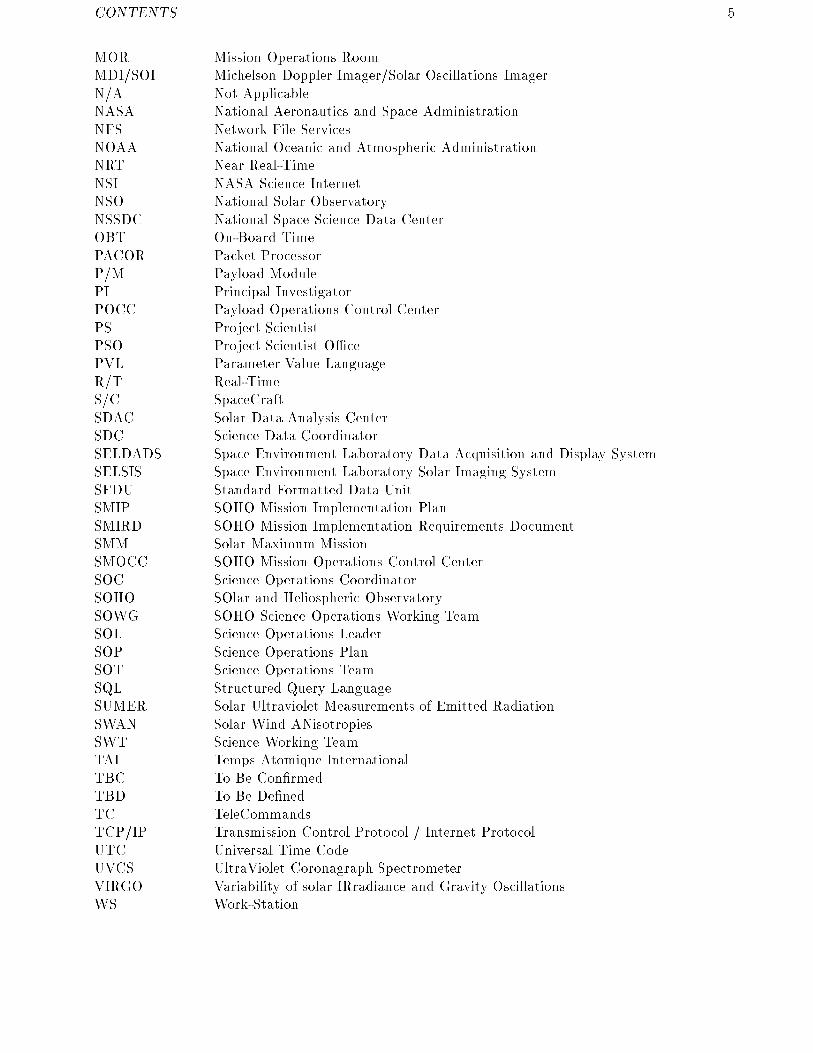
List of Acronyms
AIT Atomic International TimeAIV Assembly-Integration-Veri�cationAO Announcement of OpportunityCCSDS Consultative Committee for Space Data SystemsCDDI Copper Distributed Data InterfaceCDF Common Data Format (SFDU data format)CDHF Central Data Handling FacilityCDS Coronal Diagnostic SpectrometerCELIAS Charge, ELement and Isotope AnalysisCEPAC COSTEP { ERNE Particle Analyser CollaborationCMS Command Management SystemCo-I Co-InvestigatorCOSTEP COmprehensive SupraThermal and Energetic Particle analyserDDF Data Distribution FacilityDSN Deep Space NetworkECS EOF Core SystemECS FRD ECS Functional Requirements DocumentEGSE Electrical Ground Support EquipmentEIT Extreme-ultraviolet Imaging TelescopeEOF Experiment Operations FacilityERNE Energetic and Relativistic Nuclei and Electron experimentESA European Space AgencyESOC European Space Operations Centre (ESA, Darmstadt)Ethernet local area network de�ned by ISO 802.3FDDI Fiber Distributed Data InterfaceFDF Flight Dynamics FacilityFITS Flexible Image Transport SystemFOT Flight Operations TeamFTP File Transfer ProtocolGCI GeoCentric InertialGDCF/Pacor ISTP Program Generic Data Capture Facility / Packet ProcessorGGS Global Geospace ScienceGI Guest InvestigatorGISC Guest Investigator Selection CommitteeGOLF Global Oscillations at Low FrequencyGSE Geocentric Solar EclipticGSFC Goddard Space Flight CenterGSM Geocentric Solar MagneticIDL Interactive Data LanguageIPD Infomation Processing DivisionISTP International Solar-Terrestrial PhysicsIUE International Ultraviolet ExplorerIWS Instrumenter WorkstationLAN Local Area NetworkLASCO Large Angle Spectroscopic COronagraphMAR Mission Analysis Room
CONTENTS 5
MOR Mission Operations RoomMDI/SOI Michelson Doppler Imager/Solar Oscillations ImagerN/A Not ApplicableNASA National Aeronautics and Space AdministrationNFS Network File ServicesNOAA National Oceanic and Atmospheric AdministrationNRT Near Real-TimeNSI NASA Science InternetNSO National Solar ObservatoryNSSDC National Space Science Data CenterOBT On-Board TimePACOR Packet ProcessorP/M Payload ModulePI Principal InvestigatorPOCC Payload Operations Control CenterPS Project ScientistPSO Project Scientist O�cePVL Parameter Value LanguageR/T Real-TimeS/C SpaceCraftSDAC Solar Data Analysis CenterSDC Science Data CoordinatorSELDADS Space Environment Laboratory Data Acquisition and Display SystemSELSIS Space Environment Laboratory Solar Imaging SystemSFDU Standard Formatted Data UnitSMIP SOHO Mission Implementation PlanSMIRD SOHO Mission Implementation Requirements DocumentSMM Solar Maximum MissionSMOCC SOHO Mission Operations Control CenterSOC Science Operations CoordinatorSOHO SOlar and Heliospheric ObservatorySOWG SOHO Science Operations Working TeamSOL Science Operations LeaderSOP Science Operations PlanSOT Science Operations TeamSQL Structured Query LanguageSUMER Solar Ultraviolet Measurements of Emitted RadiationSWAN Solar Wind ANisotropiesSWT Science Working TeamTAI Temps Atomique InternationalTBC To Be Con�rmedTBD To Be De�nedTC TeleCommandsTCP/IP Transmission Control Protocol / Internet ProtocolUTC Universal Time CodeUVCS UltraViolet Coronagraph SpectrometerVIRGO Variability of solar IRradiance and Gravity OscillationsWS Work-Station

List of Figures
1.1 SOHO spacecraft schematic view : : : : : : : : : : : : : : : : : : : : : : : : : : : : : : : : 91.2 SOHO ground system: basic functions related to science operations : : : : : : : : : : : : : : 10
2.1 SOHO planning cycle : : : : : : : : : : : : : : : : : : : : : : : : : : : : : : : : : : : : : : 152.2 SOHO telemetry and real time operation plan : : : : : : : : : : : : : : : : : : : : : : : : : 162.3 One day SOHO observing plan (Coronal instruments), Day D : : : : : : : : : : : : : : : : : 172.4 One day SOHO observing plan (Coronal instruments), Day D+1 : : : : : : : : : : : : : : : 18
6

List of Tables
1.1 SOHO payload : : : : : : : : : : : : : : : : : : : : : : : : : : : : : : : : : : : : : : : : : 8
2.1 Schedule for SOHO planning meetings : : : : : : : : : : : : : : : : : : : : : : : : : : : : : 142.2 Transient events to be studied by the use of ags : : : : : : : : : : : : : : : : : : : : : : : 222.3 Flag generating and receiving instruments on SOHO : : : : : : : : : : : : : : : : : : : : : : 22
3.1 Ancillary data parameter : : : : : : : : : : : : : : : : : : : : : : : : : : : : : : : : : : : : 243.2 Summary Data File I: Images (size per day) : : : : : : : : : : : : : : : : : : : : : : : : : : 253.3 Summary Data File II: Parameters (size per day) : : : : : : : : : : : : : : : : : : : : : : : 253.4 Summary Data File III: Observation programmes (size per day) : : : : : : : : : : : : : : : : 253.5 Processed science data : : : : : : : : : : : : : : : : : : : : : : : : : : : : : : : : : : : : : 263.6 Data availability : : : : : : : : : : : : : : : : : : : : : : : : : : : : : : : : : : : : : : : : 28
7

Chapter 1
Mission Overview
1.1 Scienti�c objectives
The SOHO satellite is a solar observatory to study: the structure, chemical composition, and dynamicsof the solar interior, the structure (density, temperature and velocity �elds), dynamics and compositionof the outer solar atmosphere, and the solar wind and its relation to the solar atmosphere. Toaccomplish this, SOHO will carry a set of telescopes to study phenomena initiated by processescommencing below the photosphere, and propagating through the photosphere, chromosphere, andthe transition region into the corona. The SOHO instruments are designed to investigate problemssuch as how the corona is heated and transformed into the solar wind that blows past the Earth at400 km/s. To do so they will have spectrometers to study the emission and absorption lines producedby the ions present in the di�erent regions of the solar atmosphere. From this information it willbe possible to determine densities, temperatures and velocities in the changing structures. Thesemeasurements are complemented by the \in situ" study of the composition and energy distribution ofthe solar wind ions and energetic particles that emanate from the coronal structures observed by thetelescopes. SOHO will thus greatly enhance our knowledge of the solar wind and its source region.
While the solar interior is the region that generates the kinetic and magnetic energy driving outeratmospheric processes, almost no direct information can be obtained about any region below thephotosphere. The neutrinos generated by the nuclear reactions, taking place in the core, are theonly direct radiation that reaches us from anything that is below the photosphere. A relativelynew technique, helioseismology, has developed in the last two decades that allows us to study thestrati�cation and the dynamical aspects of the solar interior. It uses the study of the acoustic andgravity waves that propagate through the interior of the Sun and can be observed as oscillatory motionsof the photosphere. An analysis of these oscillations allows us to determine the characteristics of theresonant cavities in which they resonate, much in the same way as the Earth's seismic waves are usedto determine the structure of the Earth interior.
To study the solar interior, SOHO will carry a complement of instruments whose aim is to study theoscillations at the solar surface by measuring the velocity (via the Doppler e�ect) and intensity changesproduced by pressure and gravity waves. The study of such oscillations requires both high resolutionimaging and long uninterrupted time series of observations. In addition, because it is paramountto understand the structure of the Sun in relation to the oscillation measurements, the total solarirradiance, or solar constant, and its variations will be measured.
8

1.2. INSTRUMENTATION 9
Investigation PI Measurements Technique Bit rate(kb/s)
HELIOSEISMOLOGY
GOLF A.Gabriel, Global Sun velocity Na-vapour resonant scattering cell 0.160IAS, Orsay, F oscillations (`=0-3) Doppler shift and circular polarization
VIRGO C.Fr�ohlich, Low degree (`=0-7) Global Sun and low resolution (12 pixels) 0.1PMOD/WRC, irradiance oscillations and imaging, active cavity radiometersDavos, CH solar constant
SOI/MDI P.Scherrer, Velocity oscillations with Doppler shift and magnetic �eld 5Stanford Univ., CA harmonic degree up to 4500 observed with Michelson Doppler Imager (+160)
SOLAR ATMOSPHERE REMOTE SENSING
SUMER K.Wilhelm, Plasma ow characteristics: Normal incidence spectrometer:50-160nm 10.5MPAE, T, density, velocity in spectral resolution 20000-40000, (or 21)Lindau, D chrom. through corona angular res.: 1.5"
CDS R.Harrison, Temperature and density in Normal and grazing incidence spectrom.: 12RAL, Chilton, UK transition region and corona 15-80nm, spectr. res. 1000-10000 (or22.5)
angular res. 3"EIT J.P.Delaboudini�ere Evolution of chromospheric Images (1024 x 1024 pixels in 42' x 42') 1
IAS, Orsay, F and coronal structures in the lines of He II, Fe IX, Fe XII, Fe XV (or26.2)UVCS J.Kohl, SAO, Electron and ion temp. Pro�les and/or intensity of several 5
Cambridge, Mass. densities, velocities in corona EUV lines (Ly �, O VI, etc.) between 1.3(1.3-10 R�) and 10 R�
LASCO G.Brueckner, NRL, Evolution, mass, 1 internal and 2 externally occulted 4.2Washington, DC momentum and energy trans. coronagraphs, Fabry-Perot (or 26.2)
in corona (1.1-30 R�) spectrometer for 1.1-3 R�
SWAN J.L.Bertaux, SA, Solar wind mass ux aniso- 2 scanning telescopes with hydrogen 0.2Verri�eres-le-Buisson,F atropies+ temporal var. absorption cell for Ly-� light
SOLAR WIND `IN SITU'
CELIAS D.Hovestadt, MPE, Energy distribution and Electrostatic de ection system, 1.5Garching, D composition (mass, charge, Time-of-Flight measurements,
ionic charge) of ions solid state detectors(0.1-1000 keV/e)
COSTEP H.Kunow, Energy distribution of Solid state and plastic 0.3Univ. of Kiel, D ions (p, He) 0.04-53 MeV/n scintillator detector telescopes
and electrons 0.04-5 MeVERNE J.Torsti, Energy distribution and Solid state and scintillator 0.71
Univ. of Turku, SF isotopic composition of crystal detector telescopesions (p - Ni) 1.4-540 MeV/nand electrons 5-60 MeV
Table 1.1: SOHO payload
1.2 Instrumentation
The investigations on-board SOHO (Table 1.1) can be divided into three main groups, accordingto their area of research : helioseismology, solar atmospheric remote sensing, and \in situ" particlemeasurements.
HelioseismologyThe helioseismology investigations primarily aim at the study of those parts of the solar oscillationsspectrum that cannot be obtained from the ground. The required sensitivity for observing the verylow modes (l � 7) and the high modes (l � 300) is di�cult to achieve from the ground because ofnoise e�ects introduced by the Earth's diurnal rotation for the low modes, and the transparency andseeing uctuations of the Earth's atmosphere for the high modes.
Solar atmospheric remote sensing
The solar atmosphere remote sensing investigations are carried out with a set of telescopes and spec-trometers that will produce the data necessary to study the dynamic phenomena that take place inthe solar atmosphere at and above the chromosphere. The plasma will be studied by spectroscopicmeasurements and high resolution images at di�erent levels of the solar atmosphere. Plasma diagnos-

10 CHAPTER 1. MISSION OVERVIEW
Figure 1.1: SOHO spacecraft schematic view
tics obtained with these instruments will provide temperature, density, and velocity measurements ofthe material in the outer solar atmosphere.
\In situ" measurements
The instruments to measure \in situ" the composition of the solar wind and energetic particles willdetermine the elemental and isotopic abundances, the ionic charge states and velocity distributionsof ions originating in the solar atmosphere. The energy ranges covered will allow the study of theprocesses of ion acceleration and fractionation under the various conditions.
1.3 Spacecraft, Orbit, Attitude
The SOHO spacecraft (Fig. 1.1) will be three-axis stabilized and point to the Sun within an accuracyof 10 arc sec and have a pointing stability of 1 arcsec per 15 minutes interval. It will consist of apayload module which accommodates the instruments and a service module carrying the spacecraftsubsystems and the solar arrays. The total mass will be about 1850kg and 1150W power will beprovided by the solar panels. The payload will weigh about 640kg and will consume 450W in orbit.
SOHO is planned to be launched in July 1995 and will be injected in a halo orbit around the L1Sun-Earth Lagrangian point, about 1.5x10⁶ km sunward from the Earth. The halo orbit will have aperiod of 180 days and has been chosen because, 1) it provides a smooth Sun-spacecraft velocity changethroughout the orbit, appropriate for helioseismology, 2) is permanently outside of the magnetosphere,appropriate for the \in situ" sampling of the solar wind and particles, and 3) allows permanentobservation of the Sun, appropriate for all the investigations. The Sun-spacecraft velocity will bemeasured with an accuracy better than 0.5 cm/s.
SOHO is being designed for a lifetime of two years, but will be equipped with su�cient on-boardconsumables for an extra four years.

1.4. OPERATIONS 11
Figure 1.2: SOHO ground system: basic functions related to science operations
1.4 Operations
The diagram in Fig 1.2 shows the basic functions that will be present for the SOHO science operations.The SOHO Experiment Operations Facility (EOF), to be located at NASA Goddard Space FlightCenter, will serve as the focal point for mission science planning and instrument operations. At theEOF, experiment PI representatives will receive real-time and playback ight telemetry data, processthese data to determine instrument commands, and send commands to their instruments, both innear real-time and on a delayed execution basis. They will be able to perform data reduction andanalysis, and have capabilities for data storage. To accomplish these ends, the appropriate experimentteams will use workstations (WS's) that will be connected to an EOF Local Area Network (LAN).Additional workstations and X-terminals will be used to support the Project Scientists (PS) and forSOHO planning and operations support sta� in the EOF. There will be connections from the EOF toexternal facilities to allow transfer of incoming data from GSFC support elements, remote investigatorinstitutes, other solar observatories, and ESA facilities. There will also be connections for the EOF to

12 CHAPTER 1. MISSION OVERVIEW
interact with the SOHO Mission Operations Control Center (SMOCC) and other required elementsat GSFC for scheduling and commanding the SOHO ight experiments. Short term and long termdata storage will be either within the EOF or at an external facility with electronic communicationaccess from the EOF.
The Deep Space Network (DSN) will receive S/C telemetry during three short (1.6 hrs) and onelong (8 hrs) station pass per day. Science data acquisition during non-station pass periods will bestored on-board and played back during the short station passes. The MDI high data rate streamwill be transmitted only during the long station pass. For 2 consecutive months per year continuousdata transmission, including MDI high data rate, will be supported by DSN. Whenever there is datatransmission, the basic science data (40 kbits/s) and housekeepig data (15 kbit/s) will be available innear real-time at the EOF. From the EOF the SOHO investigators will control the operation of theinstruments via the Payload Operations Control Center (POCC). The latter will verify and up-linkthe commands submitted by the experimenters.
Some SOHO instruments (CEPAC, CELIAS, VIRGO, GOLF, and SWAN) will generally operate au-tomatically and will not need near real-time operational control except for surveillance of housekeepingdata. Other instruments, those of the coronal imaging investigators, will be operated interactivelyevery day in real (or near real-) time.
The EOF has the following functions:
a) Provides the means with which the PI teams participating in the SOHO programme can monitorand, via SMOCC, control their instruments on-board the spacecraft.
b) Is the center where the solar atmosphere investigators of SOHO will coordinate and plan thenear real-time operation of their instruments, and will be the focal point on the one hand, forthe overall SOHO science operations planning, and on the other, for coordinating science studiesthrough the organisation of campaigns and data analysis workshops.
c) Provides electronic interfaces with the appropriate data bases and networks to support the WS'sactivities and to provide the necessary input from ground stations and other spacecraft data forthe planning of the SOHO science operations.
d) Provides data storage for science, engineering and housekeeping data; common data (attitude,orbit and spacecraft housekeeping) are also stored there. Cataloging capabilities are also avail-able.
A complete description of the EOF is found in chapter 4.

Chapter 2
SOHO Operations Policy and
Requirements
2.1 Operations Plan
2.1.1 Overview
2.1.1.1 Routine operation
The SWT will set the overall science policy and direction for mission operations, set priorities, resolvecon icts and disputes, and consider Guest Investigator observing proposals. During SOHO scienceoperations, the SWT will meet every three months to consider the quarter starting in one month's timeand form a general scienti�c plan. If any non-standard DSN contacts are required, the requests mustbe formulated at this quarterly meeting. The three-month plan will then be re�ned during the monthlyplanning meetings (see 2.1.2) of the Science Operations Team (SOT), composed of those PIs or theirteam members with IWSs at the EOF, which will allocate observing sessions to speci�c programs.At weekly meetings of the SOT (2.1.3) , coordinated timelines will be produced for the instruments,together with detailed plans for spacecraft operations. Daily meetings of the SOT (2.1.4) will optimize�ne pointing targets in response to solar conditions and adjust operations if DSN anomalies occur.
2.1.1.2 Responsibilities
While the Project Scientist (PS) will be responsible for the implementation of the scienti�c operationsplan, execution of the plan will be carried out by the SOT. On a rotating basis, one of the PIs or theirrepresentatives at the EOF will serve as the Science Operations Leader (SOL). The SOL will serve forapproximately 10 days, starting with the weekly planning meeting and continuing through the weekof operations. The SOL will
� chair the weekly planning meeting and the daily meetings during the following week
� be responsible for the successful execution of the weekly plan.
To provide operational continuity over the course of the SOHO mission, and from one SOL's tenureto the next, a Science Operations Coordinator (SOC), who is not a member of any of the PI teams,will work daily with the SOL and SOT. The SOC's role is to
� produce and distribute an integrated science plan resulting from the daily meetings
� maintain the monthly scienti�c planning schedule
13
14 CHAPTER 2. SOHO OPERATIONS POLICY AND REQUIREMENTS
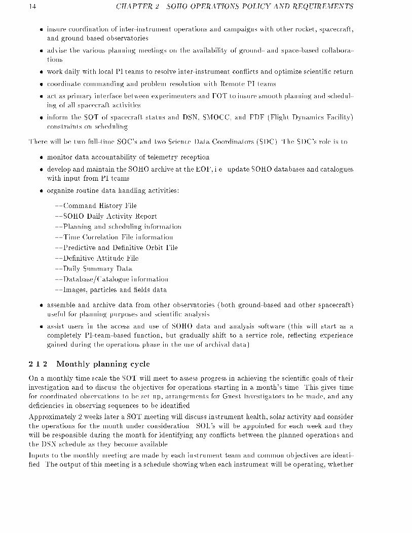
� insure coordination of inter-instrument operations and campaigns with other rocket, spacecraft,and ground based observatories
� advise the various planning meetings on the availability of ground- and space-based collabora-tions
� work daily with local PI teams to resolve inter-instrument con icts and optimize scienti�c return
� coordinate commanding and problem resolution with Remote PI teams
� act as primary interface between experimenters and FOT to insure smooth planning and schedul-ing of all spacecraft activities
� inform the SOT of spacecraft status and DSN, SMOCC, and FDF (Flight Dynamics Facility)constraints on scheduling
There will be two full-time SOC's and two Science Data Coordinators (SDC). The SDC's role is to
� monitor data accountability of telemetry reception
� develop and maintain the SOHO archive at the EOF, i.e. update SOHO databases and catalogueswith input from PI teams
� organize routine data handling activities:
{ Command History File.
{ SOHO Daily Activity Report.
{ Planning and scheduling information.
{ Time Correlation File information.
{ Predictive and De�nitive Orbit File.
{ De�nitive Attitude File.
{ Daily Summary Data.
{ Database/Catalogue information.
{ Images, particles and �elds data.
� assemble and archive data from other observatories (both ground-based and other spacecraft)useful for planning purposes and scienti�c analysis
� assist users in the access and use of SOHO data and analysis software (this will start as acompletely PI-team-based function, but gradually shift to a service role, re ecting experiencegained during the operations phase in the use of archival data)
2.1.2 Monthly planning cycle
On a monthly time scale the SOT will meet to assess progress in achieving the scienti�c goals of theirinvestigation and to discuss the objectives for operations starting in a month's time. This gives timefor coordinated observations to be set up, arrangements for Guest Investigators to be made, and anyde�ciencies in observing sequences to be identi�ed.
Approximately 2 weeks later a SOT meeting will discuss instrument health, solar activity and considerthe operations for the month under consideration. SOL's will be appointed for each week and theywill be responsible during the month for identifying any con icts between the planned operations andthe DSN schedule as they become available.
Inputs to the monthly meeting are made by each instrument team and common objectives are identi-�ed. The output of this meeting is a schedule showing when each instrument will be operating, whether
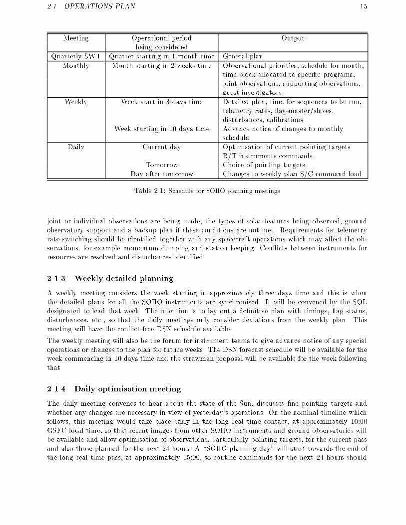
2.1. OPERATIONS PLAN 15
Meeting Operational period Outputbeing considered
Quarterly SWT Quarter starting in 1 month time General plan
Monthly Month starting in 2 weeks time Observational priorities, schedule for month,time block allocated to speci�c programs,joint observations, supporting observations,guest investigators
Weekly Week start in 3 days time Detailed plan, time for sequences to be run,telemetry rates, ag-master/slaves,disturbances, calibrations.
Week starting in 10 days time Advance notice of changes to monthlyschedule
Daily Current day Optimisation of current pointing targets.R/T instruments commands
Tomorrow Choice of pointing targetsDay after tomorrow Changes to weekly plan S/C command load
Table 2.1: Schedule for SOHO planning meetings
joint or individual observations are being made, the types of solar features being observed, groundobservatory support and a backup plan if these conditions are not met. Requirements for telemetryrate switching should be identi�ed together with any spacecraft operations which may a�ect the ob-servations, for example momentum dumping and station keeping. Con icts between instruments forresources are resolved and disturbances identi�ed.
2.1.3 Weekly detailed planning
A weekly meeting considers the week starting in approximately three days time and this is whenthe detailed plans for all the SOHO instruments are synchronised. It will be convened by the SOLdesignated to lead that week. The intention is to lay out a de�nitive plan with timings, ag status,disturbances, etc., so that the daily meetings only consider deviations from the weekly plan. Thismeeting will have the con ict-free DSN schedule available.
The weekly meeting will also be the forum for instrument teams to give advance notice of any specialoperations or changes to the plan for future weeks. The DSN forecast schedule will be available for theweek commencing in 10 days time and the strawman proposal will be available for the week followingthat.
2.1.4 Daily optimisation meeting
The daily meeting convenes to hear about the state of the Sun, discusses �ne pointing targets andwhether any changes are necessary in view of yesterday's operations. On the nominal timeline whichfollows, this meeting would take place early in the long real time contact, at approximately 10:00GSFC local time, so that recent images from other SOHO instruments and ground observatories willbe available and allow optimisation of observations, particularly pointing targets, for the current passand also those planned for the next 24 hours. A \SOHO planning day" will start towards the end ofthe long real time pass, at approximately 15:00, so routine commands for the next 24 hours should

16 CHAPTER 2. SOHO OPERATIONS POLICY AND REQUIREMENTS
Figure 2.1: SOHO planning cycle
be uplinked by 15:00 to allow for checking and contingency. Figure 2.1 and 2.2 summarize the SOHOplanning cycle activities.
2.1.5 S/C operations time line
Fig 2.2 shows the proposed overall time line of operations. The time of the long real-time operation(MDI high data rate) has been chosen to be day-light in GSFC and to overlap about half time withthe Canary Islands observatories and with the USA western observatories. The 2-month continuousoperation is arbitrary selected. It is expected that both the time of the day and the period of theyear for the MDI high data rate will have to be adapted to DSN capabilities both for technical andscheduling reasons.
It is also expected that the Soho SWT will, on certain occasions, for correlative studies with particularground observations or with other space missions, request modi�cations to the baseline operationsschedule for limited periods of time.
2.1.6 Commanding schedule
During the real time operation periods the individual investigators will send their commands as neededfrom their workstations. It is required that the command processing time from WS to spacecraft beless than one minute. Real-time commanding rate will be typically less than 100 per hour, with peaksof about 10-20 per minute.
2.1.7 Instruments timeline: sample
This two day timeline is intended to show the degree of interaction and coordination between theinstruments during a \typical" day (Fig. 2.3 and 2.4). At some times all of the instruments will beaddressing a common objective, at other times joint science will be carried out by smaller number and

2.1. OPERATIONS PLAN 17
Figure 2.2: SOHO telemetry and real time operation plan

18 CHAPTER 2. SOHO OPERATIONS POLICY AND REQUIREMENTS
Figure 2.3: One day SOHO observing plan (Coronal instruments), Day D
there will be occasions when instruments will be working individually. Naturally there is a tremendousscope for variation.
Notes:
� TIME refers to local i.e. GSFC time. 07:00 is noon GMT.
� RT is when Real Time contact through the DSN is scheduled.
� SUPPORT: C denotes nominal observing time at the Canaries, W at the US West coast obser-vatories and H at Hawaii. MDI (M) is when an MDI magnetogram is taken. This is scheduledfor the end of the short real time passes to enable the tape recorder to be dumped �rst, but atthe beginning of the low real time pass so that it is coincident with the EIT image.
02:00 CDS and SUMER check instrument performance and optimise observing programs (particularlypointing) for the next session. UVCS and LASCO observe a streamer which may give a CME.
03:25 MDI make a magnetogram.
07:00 Telemetry format 2 is used to enable EIT and LASCO to make full Sun images. MDI makemagnetogram.

2.1. OPERATIONS PLAN 19
Figure 2.4: One day SOHO observing plan (Coronal instruments), Day D+1
07:30 - 09:00 CDS and SUMER make a series of short interactive observations to identify featuresto be studied during the rest of the real time pass and features to be studied collectively during thefollowing SOHO day. EIT carry out a bright point survey. LASCO continue synoptic studies.
10:00 Daily SOHO meeting which optimises the plan for the day starting at 15:00 and considers theplan for the day after.
14:00 EIT repeat their bright point survey.
15:00 SOHO observing day starts. All instruments concentrating on the same area with the sameobjectives.
20:00 CDS and SUMER check instrument performance and optimise observing programs (particularlypointing) for the next session. Every 2 days SUMER will make a full Sun scan to give intensity andvelocity maps. EIT, UVCS and LASCO start synoptic observations.
2.1.8 Coordinated campaigns
Within SOHO
During agreed periods one or several experiment teams and, if agreed, teams from other spacecraft orground observatories will run, in collaboration, observation campaigns to address speci�c topics. The

20 CHAPTER 2. SOHO OPERATIONS POLICY AND REQUIREMENTS
periods of two-months continuous near real-time observation will probably be the most convenient forcampaigns that require continuous observation during more than 8 hours, or that require coordinationwith ground observations only feasible from particular observatories around the world. For eachcampaign a campaign leader will be responsible for the coordination.
Examples:
� LASCO, SWAN and SUMERPossible coordinated cometary observations (known or new). This should be organized on rel-atively short notice. Extension and magnitude of polar coronal holes. This can be done on aslower time schedule.
� LASCO, UVCS, EIT, SUMER, CDS and MDIA candidate structure emerges from the East limb, it is tracked by LASCO and UVCS, followedby EIT, SUMER, CDS, MDI when it transits the disk, and then LASCO and UVCS when itdisappears beyond the West limb.
With ground-based observatories
If the ground-based observatory is one that has electronic links that allow near real-time imagingtransmission to and from the EOF, the coordination will be no di�erent than if the ground basedobservatory were one of the SOHO experiments.
If no real-time data transmission is needed or possible, the coordinated operation will be an agreedtime of simultaneous observations.Generally speaking the coordinated observations with ground observatories will need a longer timelead in their planning to insure availability of the facility and coincidence of the SOHO real-timecoverage.
2.2 Conventions
The following conventions apply to facilitate the coordination of science planning, expedite the ex-change of data between di�erent instrument teams, and enhance the overall science activities.
2.2.1 Spacecraft time
The SOHO On Board Time (OBT) will use the CCSDS format, level 1 (TAI reference, 1958 January1 epoch), as discussed in section 3.3.9 of the SOHO Experiment Interface Document Part A (Issue1). The SOHO OBT is an unsegmented time code with a basic time equal to 1 second and a valuerepresenting the number of seconds from 1 January 1958 based on International Atomic Time. TheOBT Pulse is adjusted to maintain the OBT within �20ms of the ground TAI.
The SOHO OBT is used to time tag the data packets sent to the EOF and to the Data DistributionFacility (DDF). The time tags for the spacecraft and instrument housekeeping packets are generatedby the spacecraft on-board data handling system. The time tags for the instrument science datapackets are inserted by the instruments generating the science data. The time tags will be providedin 6 bytes; the �rst 4 bytes are TAI seconds (20 to 231 seconds) and the last 2 bytes are fractions of asecond with the resolution of the On Board Time Pulse (2�11 seconds).
The SOHO Daily Pulse is generated every 86,400 seconds, and is synchronized to the TAI with anaccuracy better than �100ms. The Daily Pulse will correspond to the beginning of a TAI \day",that is the Daily Pulse will occur at the zeros of TAI modulo 86,400. As of 1 January 1993, thedi�erence between TAI midnight and 00:00 UTC was 27 seconds. Since July 1st 1993 UTC-TAI ={28 sec (TBC).

2.2. CONVENTIONS 21
The helioseismology experiments plan to center one minute observations on the TAI minute, that iswhere TAI modulo 60 is zero.
2.2.2 Ground time
Coordinated Universal Time (UTC) will be used as the operational time reference in the ExperimentOperations Facility. The \SOHO operations day" is de�ned to begin at 00:00 UTC and the computersystems in the SMOCC and EOF will be synchronized to run on UTC.
2.2.3 Solar rotation axis
The solar rotation axis will be calculated using the Carrington ephemeris elements. These elementsde�ne the inclination of the solar equator to the ecliptic as 7.25 degrees, and the longitude of theascending node of the solar equator on the ecliptic as (75:76 + 0:01397 � T )�, where T is the time inyears from J2000.0.
The solar rotation axis used for alignment of the SOHO spacecraft will be determined from theCarrington ephemeris elements. The Experiment Interface Document Part A (Issue 1, Rev 3) lists thelongitude of the ascending node of the solar equator as 75.62� and the position of the pole of the solarequator in celestial coordinates as 286.11� right ascension and 63.85� declination. This de�nition isconsistent with a solar rotation axis determined from the Carrington elements for a date of 1 January1990. As mentioned in the EID Part A, this information must be updated for the actual launch date.
Heliographic longitudes on the surface of the Sun are measured from the ascending node of the solarequator on the ecliptic on 1 January 1854, Greenwich mean noon, and are reckoned from 0 to 360� inthe direction of rotation. Carrington rotations are reckoned from 9 November 1853, 00:00 UT with amean sidereal period of 25.38 days, and are designated as CR1903 etc..
2.2.4 Inter-instrument ag reference coordinates
The spacecraft optical axes are de�ned with respect to the optical alignment cube of the Fine PointingSun Sensor, with the optical X axis (X0) nominally perpendicular to the spacecraft launcher separationplane and pointing from the separation ring through the spacecraft. The spacecraft optical Y axis(Y0) is along the direction of the solar panel extension with positive Y0 pointing from the interior ofthe spacecraft towards the UVCS instrument.
The orientation of the SOHO spacecraft is planned to have the spacecraft optical X axis (X0) pointingtowards the photometric center of the Sun, and the spacecraft optical Z axis (Z0) oriented towardsthe north ecliptic hemisphere such that the (X0,Z0) plane contains the Sun axis of rotation. As suchthe Y0 axis will be parallel to the solar equatorial plane pointing towards the east (opposite to thesolar rotation direction). ESA will be responsible for achieving this orientation with the misalignmentmargins de�ned in the EID-A.
A standard coordinate system is required for joint observations between instruments on the ground(for test purposes) and in space. This system, designated (Xii,Yii), will be de�ned as follows: Onthe ground, the Yii axis is parallel to the spacecraft Z0 axis and the Xii axis is anti-parallel to thespacecraft Y0 axis. In space, the (Y0,Z0) system is however no longer accessible. We will thereforede�ne a virtual system (Y�0,Z
�0), which is nominally coincident with (Y0,Z0) and where Y�0 is perfectly
aligned with the solar equator and its origin is at the Sun centre, and de�ne (Xii,Yii) in space as aboveusing the virtual system (Y�0,Z
�0).
The inter-instrument ag system (Xii,Yii) thus has its origin at the Sun centre, its Yii axis is in theplane containing the solar rotation axis pointing north, and its Xii axis positive towards the west limb.

22 CHAPTER 2. SOHO OPERATIONS POLICY AND REQUIREMENTS
Each instrument participating in the ag exchange is reponsible for determining its orientation withrespect to the (Xii,Yii) system and report the coordinates of their observations in (Xii,Yii) coordinatesin units of 2 arcsec. O�-limb observations need special treatment if Xii, Yii> 1022".
2.2.5 Spacecraft orbit coordinates
The Orbit data will describe the position and motion of the spacecraft, and it will be available inseveral coordinate systems including: geocentric inertial (GCI) coordinates for the J2000 system;geocentric solar ecliptic (GSE); geocentric solar magnetospheric (GSM) coordinates; and HeliocentricEcliptic coordinate system.
The GSE coordinate system is de�ned as follows: The origin is Earth centered, with the X axis pointingfrom the center of the Earth to the center of the Sun; the Y axis lies in the ecliptic plane and points inthe opposite direction of the Earth's orbital motion; the Z axis completes a right-handed orthogonalcoordinate system and is parallel to the ecliptic pole. The Sun position is the true \instantaneous"position rather than the \apparent" (light-time delayed or aberrated) position. The ecliptic is thetrue ecliptic of date.
The Heliocentric Ecliptic coordinate system is de�ned as follows: the origin is Sun centered, withthe Z axis parallel to the ecliptic pole with positive north of the ecliptic plane; the X-Y plane liesin the ecliptic plane and the X axis points towards the �rst point of Aries; the Y axis completes aright-handed orthogonal coordinate system.
The GCI coordinate system is de�ned as follows: Earth centered, where the X axis points from theEarth towards the �rst point of Aries (the position of the Sun at the vernal equinox). This directionis the intersection of the Earth's equatorial plane and the ecliptic plane | thus the X axis lies in bothplanes. The Z axis is parallel to the rotation axis of the Earth and the Y axis completes a right-handedorthogonal coordinate system. As mentioned above, the X axis is the direction of the mean vernalequinox of J2000. The Z axis is also de�ned as being normal to the mean Earth equator of J2000.
The GSM coordinate system is de�ned as follows: again this system is Earth centered and has its Xaxis pointing from the Earth towards the Sun. The positive Z axis is perpendicular to the X axis andparalle to the projection of the negative dipole moment on a plane perpendicular to the X axis (thenorthern magnetic pole is in the same hemisphere as the tail of the magnetic moment vector). Againthis is a right-handed orthogonal coordinate system.
2.3 Inter-instrument ags
In crude terms, a ag is a message sent by an instrument to another instrument, which enablesthe latter one to respond by operating in a more e�cient manner. The implication is that thedata/command loop for responses via the ground would be far too long to be of use for the aggedevent.
The coronal extreme ultraviolet and ultraviolet instrumentation on-board SOHO will have limited�elds of view and limited telemetry streams. For this reason, one has to examine ways of increasingthe e�ciency of the available system. Short time scale events may best be detected by one SOHOinstrument which may relay information to the others to generate operating mode changes or moreprecise pointing.
With SOHO we are considering a range of ags which will enable an e�cient programme for observinga range of features. The inputs to this study from the various experiment teams have resulted in thelist of ags given in Tables 2.2 and 2.3. For each entry we list the event-type, the time-scale needed fora response, the instrument which generates the ag, and the instruments which may wish to respond

2.3. INTER-INSTRUMENT FLAGS 23
Event type Response time Identi�ed activity
Jets/Turbulent events <Minute Pocket of Doppler shifts
Micro/Sub ares Seconds Brightening
Bright points <Minutes BrighteningActivated prominences Tens of minutes Increased Doppler shifts
Eruptive prominences Minutes Transverse motion or detectionof prominence in corona
Coronal Mass Ejection Minutes \Precursor" brightenings orEjection in corona
Flares Seconds Extreme brightenings
Table 2.2: Transient events to be studied by the use of ags
to such a ag. Since the features being studied are not necessarily as easy to identify as a are, wealso de�ne the nature of the activity which can be monitored in order to generate the ag.
Event type Originator Receiver
Jets/Turbulent events SUMER / CDS CDS / SUMER
Micro/Sub ares SUMER / CDS CDS / SUMER
Bright points EIT SUMER / CDSCDS SUMER
Activated prominences SUMER CDS / LASCO / UVCS
Eruptive prominences CDS / SUMER LASCO / UVCSLASCO CDS / SUMER
Coronal Mass Ejection CDS LASCO / UVCSLASCO UVCS/ CDS / SUMER
Flares EIT / CDS / SUMER EIT / CDS / SUMER / UVCS /LASCO / MDI
Table 2.3: Flag generating and receiving instruments on SOHO
Timing (for ag to be read by receiving instrument): within 16 seconds of being detected by generator.Form of ag words: 2 x 10 bit words (X, Y location on Sun)
1 x 4 bit word (Identi�er)Notes: all ags sent to all receiving instruments
one ag generating instrument enabled at a timeplanned from EOF
The rules and conventions adopted in the generation and reception of ags are described in Annex C.
Chapter 3
Data
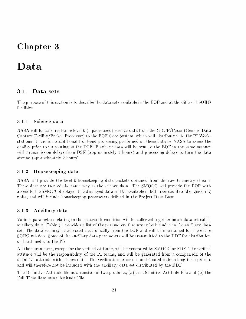
3.1 Data sets
The purpose of this section is to describe the data sets available in the EOF and at the di�erent SOHOfacilities.
3.1.1 Science data
NASA will forward real-time level 0 (=packetized) science data from the GDCF/Pacor (Generic DataCapture Facility/Packet Processor) to the EOF Core System, which will distribute it to the PI Work-stations. There is no additional front-end processing performed on these data by NASA to assess thequality prior to its routing to the EOF. Playback data will be sent to the EOF in the same mannerwith transmission delays from DSN (approximately 3 hours) and processing delays to turn the dataaround (approximately 2 hours).
3.1.2 Housekeeping data
NASA will provide the level 0 housekeeping data packets obtained from the raw telemetry stream.These data are treated the same way as the science data. The SMOCC will provide the EOF withaccess to the SMOCC displays. The displayed data will be available in both raw counts and engineeringunits, and will include housekeeping parameters de�ned in the Project Data Base.
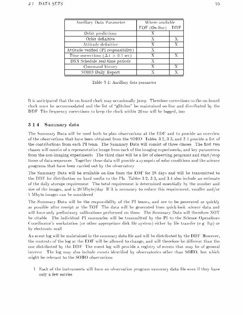
3.1.3 Ancillary data
Various parameters relating to the spacecraft condition will be collected together into a data set calledancillary data. Table 3.1 provides a list of the parameters that are to be included in the ancillary dataset. The data set may be accessed electronically from the EOF and will be maintained for the entireSOHO mission. Some of the ancillary data parameters will be transmitted to the DDF for distributionon hard media to the PIs.
All the parameters, except for the veri�ed attitude, will be generated by SMOCC or FDF. The veri�edattitude will be the responsibility of the PI teams, and will be generated from a comparison of thede�nitive attitude with science data. The veri�cation process is anticipated to be a long-term processand will therefore not be included with the ancillary data set distributed by the DDF.
The De�nitive Attitude �le now consists of two products, (a) the De�nitive Attitude File and (b) theFull Time Resolution Attitude File.
24
3.1. DATA SETS 25
Ancillary Data Parameter Where availableEOF (On-line) DDF
Orbit predictions X
Orbit de�nitive X X
Attitude de�nitive X X
Attitude veri�ed (PI responsibility) X
Time corrections (� t > 0:1 sec) X X
DSN Schedule real-time periods X
Command history X X
SOHO Daily Report X X
Table 3.1: Ancillary data parameter
It is anticipated that the on-board clock may occasionally jump. Therefore corrections to the on-boardclock must be accommodated and the list of \glitches" be maintained on-line and distributed by theDDF. The frequency corrections to keep the clock within 20ms will be logged, too.
3.1.4 Summary data
The Summary Data will be used both to plan observations at the EOF and to provide an overviewof the observations that have been obtained from the SOHO. Tables 3.2, 3.3, and 3.4 provide a list ofthe contributions from each PI team. The Summary Data will consist of three classes. The �rst twoclasses will consist of a representative image from each of the imaging experiments, and key parametersfrom the non-imaging experiments. The third class will be a list of observing programs and start/stoptimes of data sequences. Together these data will provide a synopsis of solar conditions and the scienceprograms that have been carried out by the observatory.
The Summary Data will be available on-line from the EOF for 28 days and will be transmitted tothe DDF for distribution on hard media to the PIs. Tables 3.2, 3.3, and 3.4 also include an estimateof the daily storage requirement. The total requirement is determined essentially by the number andsize of the images, and is 20Mbyte/day. If it is necessary to reduce this requirement, smaller and/or1 Mbyte images can be considered.
The Summary Data will be the responsibility of the PI teams, and are to be generated as quicklyas possible after receipt at the EOF. The data will be generated from quick-look science data andwill have only preliminary calibrations performed on them. The Summary Data will therefore NOTbe citable. The individual PI summaries will be transmitted by the PI to the Science OperationsCoordinator's workstation (or other appropriate disk �le system) either by �le transfer (e.g. ftp) orby electronic mail.
An event log will be maintained in the summary data �le and will be distributed by the DDF. However,the contents of the log at the EOF will be allowed to change, and will therefore be di�erent than theone distributed by the DDF. The event log will provide a registry of events that may be of generalinterest. The log may also include events identi�ed by observatories other than SOHO, but whichmight be relevant to the SOHO observations.
1. Each of the instruments will have an observation program summary data �le even if they haveonly a few entries.

26 CHAPTER 3. DATA
MDI Full disk magnetogram, 1024 x 1024 x 2 byte (2MB)Full disk continuum, 1024 x 1024 x 2 byte (2MB)
EIT Full disk Fe IX, 1024 x 1024 x 2 byte (2MB)Full disk Fe XII, 1024 x 1024 x 2 byte (2MB)Full disk Fe XV, 1024 x 1024 x 2 byte (2MB)Full disk He II, 1024 x 1024 x 2 byte (2MB)
UVCS 1.2-10 R� Corona Ly �, 256 x 256 x 1 byte (0.25 MB)1.2-10 R� Coronal Temperature, 256 x 256 x 1 byte (0.25 MB)
LASCO 1.1-30 R� Corona White Light, 1024 x 1024 x 2 byte (2 MB)1.1-3 R� Corona Fe XIV, 1024 x 1024 x 1 byte (1 MB)1.1-3 R� Corona Fe X, 1024 x 1024 x 1 byte (1 MB)1.1-3 R� Corona Ca XV, 1024 x 1024 x 1 byte (1 MB)
Table 3.2: Summary Data File I: Images (size per day)
VIRGO Solar constant, SPM, LOI for each pixel (1 value/day) (0.1 kB)
SWAN Observations sensor 1 and 2 (1.5 kB)
CELIAS Solar wind speed, heavy ion ux (5 minutes averages) (1.5 kB)
CEPAC 17 particles ux every 5 min or 15 min (12 kB)
Table 3.3: Summary Data File II: Parameters (size per day)
SUMER Operation modes, time, heliographic area covered (16 kB)
CDS Operation modes, time, heliographic area covered (16 kB)
SWAN Operation modes, area observed, start/stop time (5 kB)Operation modes, time, heliographic area covered (5 kB)
UVCS Operation modes, sequence number, FOV, start/stop time (10 kB)
LASCO Operation Modes, time, events (10 kB)
Table 3.4: Summary Data File III: Observation programmes (size per day)

3.1. DATA SETS 27
GOLF Time series of global velocity �eld
VIRGO Times series of irradiance
MDI Time series of full disk velocity, intensity and magnetograms imagesTime series of high resolution velocity, intensity and magnetograms imagesTime series of mode amplitudes, low resolution velocity, intensity images
SUMER UV spectra, images (scans) and time series
CDS EUV spectra, images (scans) and time series
EIT Full disk EUV images, time series of selected regions
UVCS UV spectra (Ly-�, O VI) and images of the solar corona out to 10 R�LASCO Time series of coronal images (white light brightness, pB, line ratios)
SWAN Antisolar Lyman-� intensity, Lyman-� maps of the sky
CELIAS Composition (mass, charge, ionic charge) and energies of solar windand suprathermal particles
CEPAC Count rates, energy spectra, and isotopic composition of energetic particles(e, p, He { Ni)
Table 3.5: Processed science data
2. The observation program will have both a planned and an executed data �le. Ideally the formatsof the planned and executed �les should be identical. In addition, it would speed up generationof the executed data �le if it could be extracted entirely from the command history log (insteadof from the instrument data streams).
3. A standard format for the observation program �le will be de�ned for all the instruments in orderto make it easier to correlate observations. The format could include Operation Mode, StartTime, Stop Time, and Observing Parameters. The Operation Mode would include instrumentname, detector, and observing sequence identi�cation. The Start and Stop Times would be in awell de�ned format (for example, yymmdd hh:mm.ss). The Observing Parameters could includeheliographic area covered, �eld of view, sequence number, events, etc. and might have the formatof parameter=value.
4. The observation program might be better as a database apart form the summary data. Inaddition, it would be a good place to start with the de�nition of a catalog and keywords. Thedisadvantage of having the observation program as a stand-alone database would be the di�cultyof updating the information. This would be less of a problem if the observation program databasecould be generated automatically from the command history log.
3.1.5 Processed science data
Each investigation group will convert the level-0 Science data and other related data into more elabo-rate data �les (or have the necessary software) for scienti�c analysis. Any processed data must have alevel greater than 0 (i.e. level 1,2, etc...). Details of the archived �les are to be found in the individualexperiment Operations Manual. Table 3.5 gives an indication of the �les to be generated.
3.1.6 Synoptic information and predictive information
The following data sets will be available at the EOF by electronic means either from SELDADS ordirectly from solar ground-based observatories. Among the \core support observatories" are Mitaka,

28 CHAPTER 3. DATA
Nobeyama, Norikura (all Japan), Huairou (China), Ondrejov (Czech Republic), Pic du Midi (France),Izana (Tenerife), Huntsville, SEL (Boulder), Sac Peak, Kitt Peak, Big Bear, Mt.Wilson, Mees, andMauna Loa (all USA).Provided data from ground stations are:
� H-� images
� Ca K images
� Full disk magnetograms
� Helium 10830 �A images
� Radio images
� Sun map with coronal holes
� Coronagraph pictures
� Solar ares monitoring
� Zurich Sunspot number
� 10.7cm Ottawa radio ux
Provided data from other S/C:
� X-ray images from Yohkoh (and other S/C, if available)
� GOES full Sun X-ray pro�les
� Key parameters from Ulysses, WIND, CLUSTER
Provision to other projects from SOHO:
� Summary Data
3.2 Dissemination and archiving
3.2.1 Data availability
Table 3.6 indicates where and when the various data sets are to be available. The exchange of databetween SOHO experimenters will facilitate the successful implementation of joint observing programsto achieve common science objectives. Electronic access to data sets remote to an individual PIscomputer system provides a quick and reliable mechanism for the collaborative exchange of data.The following plan for data availability requires a submission of data from the PI teams as soon aspossible after receipt, and hopefully within 24 hours. Therefore most of the inputs to the summarydata should be generated by automated procedures. For example, the planned observing scheduleshould be generated from the planned command load.
In Table 3.6, an X indicates data availability at that facility. If a time is indicated, then the data setwill be available within the time speci�ed. The MDI High Data Rate Data will be delivered directly toStanford University and will not go through the EOF. However the MDI magnetogram data occurringat the end of every tape recorder playback will be delivered to the EOF.
The spacecraft housekeeping shall be archived for electronic access from the EOF for 28 days afterdata collection. The data may be kept as digital counts, but conversion to engineering units would bepreferable.
The maintenance of quick look science data is the responsibility of the PI teams. While it is desirablethat the most recent 30 days be kept on-line or near on-line, it is recognized that each experimentteam will have di�erent requirements and di�erent capabilities and no �xed requirement for on-linedata retention can be imposed on the PI teams.

3.2. DISSEMINATION AND ARCHIVING 29
Where available
PI WS EOF (On-line) DDF
CatalogsAncillary Data X XSummary Data X XS/C Level 0 Data X XInstrument Quick Look Data X XInstrument Final Data X X
Ancillary Data X XDe�nitive Orbit 1 week 1 weekDe�nitive Attitude 1 week 1 weekCommand History 1 week 1 week
Summary DataImages 1 day 1 day 1 weekParameters 1 day 1 day 1 weekPlanned observations 1 day 1 dayExecuted observations 1 day 1 day 1 week
S/C Level 0 DataHousekeeping - real-time <1 minute <1 minuteHousekeeping - playback 3.5-5 hour 3.5-5 hourHousekeeping - combined 4 days X
Instrument Quick Look DataHousekeeping - real-time <1 minute <1 minuteHousekeeping - playback 3.5-5 hour 3.5-5 hourHousekeeping - combined 4 days XScience - real-time <1 minute <1 minuteScience - playback 3.5-5 hour 3.5-5 hourScience - combined 4 days X
MDIMagnetogram <1 minute <1 minuteHigh Data Rate (to Stanford) 1 week X
Table 3.6: Data availability

30 CHAPTER 3. DATA
3.2.2 Data Distribution Facility
The DDF will mail a hard copy (currently, in CD-ROM) of the respective level{0 science/housekeepingand ancilliary data to each PI within 30 days of receipt at GSFC. The PI is then responsible for furtherdistribution to Co-Is and support institutions. In addition, such telemetry data will be available in theform of "snapshots" for limited call up to approved participating organisations. Those data, availableelectronically from the Central Data Handling Facility (CDHF), will represent the most recent 8 daysof information.
Each PI will receive a copy of his own investigation data set, and of any other if so agreed, after 30days of reception by DDF.
CDHF will process the key parameters for CELIAS and CEPAC to be included in the Summary Data.The Summary Data and the As-Run Plan, created and maintained on line at the EOF, is sent toCDHF for hard copy (CD-ROM) distribution. Both CDHF and EOF will keep these data online.
3.2.3 EOF
A number of SOHO participating institutes (PIs and others) will hold archives of the Science andprocessed science data corresponding to the experiment of their responsibility.
The central archiving facility for processed data is being developed at the EOF. This archive will holdthe complete set of SOHO data with the only exception of the high data rate MDI helioseimologydata set.
The following data sets will be generated for SOHO and available from the EOF archive:
� Telemetry Science Data (�nal level{0 distribution).
� Housekeeping Data (�nal level{0 distribution).
� Ancilliary Data
� Summary Data (including the As Run Plan).
� Event �le
� Synoptic data (from ground-based and space-based observatories).
� Processed Data (�les that are ready for scienti�c data analysis). Most of the data exchangebetween scientists and groups will be done with these data sets. The processed data will begenerated at the EOF or/and the PI or collaborating institutes or observatories.
3.2.4 Databases
The various database catalogs may be accessed electronically over the EOF LAN. The catalogs will bedata base tables that are linked together using standard relational data base techniques. A standardquery language (SQL) is used to access the databases, but an interface program has been developed inorder to use more user-friendly front ends to the EOF archive. The �rst interface is World-Wide-Webbased and its available to anyone with Internet access. The second one is based on IDL and will beused mainly within the EOF for data analysis purposes.
The type of information stored into these database �les will fall into several categories. The �rstcategory will consist of information about observing programs. For this category, a standard set of data�eld names and their de�nition has been prepared to provide uniformity in developing the individualexperiment databases. Not all �elds names may apply to a particular instrument, in which case that�eld will simply be blank for that instrument. The type of information stored in these databases willinclude information like identi�cation of what type of observing program was followed, the purpose

3.3. STANDARD FORMATS 31
or target of the observing program, the time range of the observing program, and the heliographicarea of the sun covered. Users will be able to simultaneously sample this information not only at theEOF, but worldwide. This will be accomplished maintaining a combined database incorporating thisinformation from all the instruments on a central �le server system using updates supplied by the PIteams. There will be two main datasets: the As Plan File, describing the upcoming observing plansof the instruments (will reside at ECS), and the As Run File detailing what was actually observed.This last �le will be part of the Summary Data set.
The second category of database �les will contain information about events that may be relevant tomore than one instrument. Exactly what information will be stored in this catalog is yet TBD, butmost likely it will contain the same information as found in the Observatory Log (section 3.1.4). Thiscould consist of information about such things as spacecraft rolls, as well as information about solarevents and features. Information for this �le will be received from several sources: CMS (spacecraftevents), ECS (global planning related events) and PI workstations. This database will also containinformation about events registered by other observatories, that may be relevant to the SOHO obser-vations. Related into this events catalog will be additional database �les which will serve to logicallyrelate the events to the individual SOHO observations, and to store information about what e�ect agiven event had on a given observation, if any.
The third category of database will contain information about scienti�c data. Several tables willdescribe science processed, summary and synoptic observations. Access to this data sets will beunrestricted unless otherwise speci�ed in the SOHO Science Working Team data rights agreements.Ancillary, summary, event and synoptic data will be in the public domain immediately after acquisition.The science processed data will be public after an initial period of restricted access.
There will be a way for users to attach comments to the individual entries in each of the database�les. The procedure used to control this process is as yet TBD.
3.3 Standard formats
3.3.1 Overview
The speci�cation and use of a standard format or set of formats enables data to be exchanged easilybetween investigators. SOHO will use the Standard Formatted Data Unit (SFDU) which is becomingmore common in data archives. For example, all data in the ISTP CDHF at NASA/GSFC must beSFDU conforming data objects. Documents describing formatting standards may be obtained from:
NASA/OSSA O�ce of Standards and TechnologyCode 933NASA Goddard Space Flight CenterGreenbelt MD 20771USA
3.3.2 SFDU
SFDU is an international standard that facilitates the exchange of information between users. TheSFDU formalism enables a description of the data to be speci�ed in a standard way and in a way thatanyone, possibly years later, can obtain from the appropriate international agency. Such agencies arecalled Control Authorities, two of which are the NASA/NSSDC and ESA/ESOC. A data descriptionthat is registered with such a Control Authority is given a unique identi�er that is included with thedata as an SFDU label (either as a separate �le or included with the data at the beginning of the data).

32 CHAPTER 3. DATA
Thus any user of the data who is unfamiliar with the data can obtain a description by contacting aControl Authority. A FORTRAN procedure is available to generate SFDU labels.
The SOHO Science Operations Working Group has adopted the SFDU formalism for any product thatis going to be distributed to the community. For example the summary data will have SFDU labels(detached) as will the orbit and attitude �les.
The SFDU is described in the following documents:
� \Draft Recommendation for Space Data System Standards: Standard Formatted Data Units |Control Authority Procedures", CCSDS 630.0-R-0.2, Consultative Committee For Space DataSystems.
� \Draft Recommendation for Space Data System Standards: Standard Formatted Data Units| Structure and Construction Rules", CCSDS 620.0-R1.1, Consultative Committee for SpaceData Systems.
� \Report Concerning Space Data System Standards: Space Data Systems Operations with Stan-dard Formatted Data Units | System and Implementation Aspects", CCSDS 610.0-G-5, Con-sultative Committee for Space Data Systems.
� \Draft Report for Space Data System Standards: Standard Formatted Data Units | A Tuto-rial", CCSDS 621.0-G-1, Consultative Committee for Space Data Systems. Distillations of thesedocuments have been included in minutes of SOWG or splinter group meetings.
The SFDU does not in itself specify the format of the data. It permits any format, either registered ornot to be used. If a non-registered format is used, then the format speci�cation needs to be includedwith the data. Three data formats that are registered are the Parameter Value Language (PVL),Flexible Image Transport System (FITS), and the Common Data Format (CDF), all of which will beused in SOHO �les.
3.3.3 PVL
The SFDU uses PVL to specify required information. It is a generalization of the format in the headerof FITS �les, and is of the form "Parameter = Value". It is an international standard also and isdescribed in the following documents:
� \Report Concerning Space Data System Standards: Parameter Value Language | A Tutorial",CCSDS 641.0 - G-1, Consultative Committee for Space Data Systems.
� \Recommendation Concerning Space Data System Standards: Parameter Value Language Spec-i�cation (CCSD0006)", CCSDS 641.0-B-1, Consultative Committee for Space Data Systems.
The catalogs that will be generated by SOHO experimenters will use PVL/FITS concepts. In order toensure that everyone is using the keywords (parameters) in a consistent way, the keywords and theirde�nitions will be registered with a Control Authority. A draft document of the keywords has beencirculated (see Annex 6 in the minutes of the 8th SOWG meeting).
3.3.4 FITS
All scienti�c data �les generated by the PI teams will be in FITS format. In particular, this appliesto the summary data, and to level-1 (and higher) data �les. An exception are the summary data �lesof the three particles experiments CELIAS, COSTEP, and ERNE which will be in CDF.
A formal description of the FITS standard can be found in \Implementation of the Flexible ImageTransport System (FITS)", available as publication NOST 100-0.3b from the O�ce of Standards

3.3. STANDARD FORMATS 33
and Technology, or by anonymous ftp from nssdca.gsfc.nasa.gov (128.183.36.23), or via DECnet fromNSSDCA::ANON DIR:[FITS] (15548::).
FITS �les facilitate interoperability by using a speci�ed binary standard for encoding data valuesindependent of the computer platform. In other words, FITS �les look the same regardless of whatcomputer the �le is sitting on, and can be copied from computer to computer without modi�cation.FITS �les are also used in a wide range of astronomical applications, and are directly supported insuch astronomical software packages as IRAF, and indirectly supported in some broader data analysispackages such as IDL.
Some standardized software for reading and writing FITS �les are available in the public domain.The FITSIO package by William Pence is a set of FORTRAN subroutines available by anonymous ftpfrom tetra.gsfc.nasa.gov (128.183.8.77). There are also IDL routines available for reading and writingFITS �les, as part of the IDL Astronomy User's Library. These are available via anonymous ftp fromidlastro.gsfc.nasa.gov (128.183.84.71), or by DECnet copy from uit::$1$DUA5:[IDLUSER] (15384::).
3.3.4.1 Primary FITS �les
The simplest form of FITS �le consists of a single FITS header and data unit. FITS headers are aseries of eighty-character card images of the form keyword=value. The keywords are restricted to amaximum of eight characters, and include a standard set of prede�ned keywords, some of which arerequired, and whatever additional keywords the experimenter wishes to de�ne.
The data unit consists of an N-dimensional data array. The size, dimensions, and datatype of thearray are described by standard FITS keywords in the header. IEEE standards are used for the binaryrepresentation of the data.
The primary FITS header and data unit can be followed by one or more FITS extensions. In that caseit is not required that there be a primary data array; the number of elements can be given as zero.There are a number of di�erent kinds of standard extension types, and there is also the possibility ofde�ning new kinds of extensions.
3.3.4.2 ASCII tables
One standard extension type, the \TABLE" extension, allows the experimenter to store an ASCIIencoded table. The format of each column in the table is de�ned individually. This extension couldbe used to store catalog-type information.
3.3.4.3 Binary tables
Similar to the \TABLE" extension, the \BINTABLE" extension allows the storage of data organizedinto a table with rows and columns. However, the data are stored with a binary representation(although ASCII �elds are allowed), and individual items in the table can be arrays rather than scalarvalues.
At the moment there is no formal standard for describing the dimensions of an array. This is principallybecause there is no one \right' way to do this. However, there is a proposal for one way to do this, the\Multidimensional Array Facility", which is given as an Appendix in the NOST FITS document, anduses TDIMn keywords in the header to describe the dimensions. This TDIM approach should meetthe needs of any SOHO instrument team that wants to use binary tables to store their data.
Binary tables represent a powerful and e�cient way of associating together a number of di�erent datavariables in a single FITS �le.

34 CHAPTER 3. DATA
3.3.4.4 The IMAGE extension
The \IMAGE" extension has been proposed by the IUE (International Ultraviolet Explorer) team asa standard for storing multiple arrays in a single FITS �le. Each IMAGE extension is basically of thesame format as the primary FITS header and data unit.
IMAGE extensions are appropriate when the number of data arrays, and hence the number of exten-sions, to store together in a single FITS �le is small. If the number of non-scalar variables is large, orthe data structure is complex, then binary tables are more appropriate.
3.3.5 CDF
The GGS/ISTP (Global Geospace Science / International Solar-Terrestrial Physics) project has adop-ted the NSSDC (National Space Science Center) CDF for use in key parameters and some other dataproducts maintained at the CDHF. The exact role of the CDHF in storing and distributing SOHOsummary data still needs to be worked out, but at the very least key parameters from certain SOHOinstruments will be incorporated into the CDHF database. Since that database uses CDF, and SOHOuses FITS, some conversion will be necessary.
CDF has some properties in common with FITS, in that it is self-describing, and that it allows theassociation of information about the data, (units, description of data axes, etc.) together with thedata arrays. The underlying physical representation, and the basic data model, are di�erent however.
The NSSDC supplies a set of standard FORTRAN and C libraries for reading and writing CDF �les onVMS and Unix computers. These are available via anonymous ftp for VMS from nssdca.gsfc.nasa.gov(128.183.36.23), or by DECnet copy from NSSDCA::ANON DIR:[CDF.CDF21- DIST] (15548::). Soft-ware for various Unix workstations are available using anonymous ftp from ncgl.gsfc.nasa.gov(128.183.10.238).
The CDHF also supplies software to aid in the generation of key parameter software in ISTP/CDF for-mat. This software is available via DECnet from ISTP::SYS$PUBLIC:[SFDU TOOLS.BLD SFDU]-(15461::) or by anonymous ftp from either istp1.gsfc.nasa.gov (128.183.92.58) or from istp2.gsfc.nasa.gov (128.183.92.59) in the directory SYS$PUBLIC:[SFDU TOOLS.BLD SFDU].
The format used by the ISTP/CDHF is a subset of the complete CDF speci�cation, and furtherspeci�es the format to promote uniformity between the di�erent ISTP data sets. This uniformityextends such things as the binary representation of data (e.g. IEEE format for oating point numbers,the same as FITS), and the representation of times.
Both FITS and CDF are supported in IDL.
3.4. USE OF SOHO DATA | DATA RIGHTS 35
3.4 Use of SOHO data | data rights
3.4.1 Introduction
The objective of a coherent policy on these aspects should be to ensure the maximum exploitation ofthe SOHO data in order to extract the best scienti�c output from the mission. For this purpose, it isnecessary to �nd a just equilibrium between the two con icting strategies. These are :
a) to open up free access to the widest possible community, thereby making available special capa-bilities and expertise from outside the SOHO teams, and
b) to protect the interests of the PI teams who have invested so much personal e�ort, and throughrewards for this e�ort to motivate them to continue to work for the collective scienti�c interest.
Leadership in applying such a policy rests with the PIs, who have a moral responsibility for maximisingthe science from the mission, as well as the structure and authority within their teams for applying awell-de�ned strategy. However, since the joint exploitation of combined data sets is a key objective ofSOHO, it is important to have joint PI or SWT agreements on this policy. This section summarizesthe policy that the SOHO PIs have agreed to abide by with respect to the utilization of the datagenerated by their instruments.
3.4.2 De�nitions
3.4.2.1 Data access rights
Two types of data access rights can be envisaged:
1. Data access for planning purposes
All SOHO PIs have the right to access all other SOHO data for the purpose of operationsplanning during the mission. They also have the right to have access to the data to survey themto evaluate their possible use for cooperative research, but not to carry out data analysis with aview to publication.
Access rights de�ned in the above manner may serve many other useful functions, e.g. to allowpotential guest investigators to verify the availability of the required data sets before �nalisingtheir proposal.
2. Data access for analysis and research
This is regulated by the data rights policy of the SOHO SWT as described in this document.Speci�c data rights policies are de�ned for the SOHO Guest Investigators (GI) (see 3.4.5) andfor SWT approved campaigns.
3.4.2.2 SOHO science projects
A proposed project must consist of a clear scienti�c objective, together with the proposed means forits accomplishment. It might or might not include the need for new observations, the de�nition ofnew observing sequences, cooperation between several SOHO instruments or with non-SOHO space orground-based observations. It can be based upon analysis of synoptic data over long periods, recordedprimarily for completely di�erent objectives. It can involve the use of a new analysis or theoreticaltechniques to analyse existing data. In spite of exibility in the form, science projects must be closelyde�ned. Otherwise, approval to follow one research aspect could be interpreted to cover a very widerange of activities.

36 CHAPTER 3. DATA
3.4.2.3 Responsibilities
PI individual responsibilities include :
a) To manage, in the broadest sense the attribution of science projects amongst their team scientistsand CoI's.
b) To advise on the selection of Guest Investigator (GI) proposals which concern their instrument.
c) To consider how wider access with appropriate controls could help in stimulating outside (GI)participation.
d) To de�ne, and announce publicly a Publication Policy. This should include a policy for initialpublications; i.e. a declared number of early papers, formally authored, which can also giverewards for those involved in technical or engineering e�ort. An on-going publications policyshould indicate the approval or vetting procedure (if any), authorship policy, etc.
SWT agreements and responsibilities include:
a) Data access policy, as suggested above.
b) Joint Public Relations activities
c) The establishment and managing of joint science projects.
d) Advice on the selection of GI joint science proposals.
e) To encourage a common strategy for the PI (Individual) policy.
3.4.2.4 Data levels
The SOHO data are distributed to the PIs by two channels.
1. A general line of SOHO data originates at the Data Distribution Facility (DDF):
� Level 0 or unprocessed data are the data distributed by the DDF to the PIs (raw data)
� Level 1 or basic data are corrected for a priori known e�ects such as at �elds of CCD'sand other instrument inherent e�ects, as well as the Sun-instrument geometry (distance,radial velocity, solar disk coordinates, etc.) and they are evaluated to physical units. Level 1data are still raw data in the sense that they do not contain corrections for e.g. degradation,which cannot be calculated right away. Level 1 data may be useful for some limited scienti�canalysis.
� Level 2 or processed (or calibrated) data will be corrected for long term degradationand calibration changes and will contain derived parameters that will be useful for scienti�cevaluation in general.
2. Another line of data originates at the EOF:
� The real time and the tape dump play back data received at the EOF by the PIs arein the same format as the level 0 data described above.
� Out of it will be produced the summary data for the Summary Data File and the
� quick look processed data to be used at the EOF for science operations planning.

3.4. USE OF SOHO DATA | DATA RIGHTS 37
3.4.3 SOHO science data access policy
The intent of the SOHO data access policy is to provide data to as wide a community
as possible and as soon as possible. From the beginning of the operational mission, the
scienti�c community is welcomed and encouraged to participate in the analysis of the SOHO
data in collaboration with the PI teams. The goal is to make fully callibrated data available
for public use through ESA and NASA archives one year after reception by the PIs.
In addition to this general policy, the following rules apply:
� For each PI team the data distribution, data rights and publication policy is de�ned in theirScience Book.
� All the PIs have the right to access the data of the other SOHO experimenters for planningpurposes in the terms de�ned in section 3.4.2.1.
� For this purpose, each PI will make the data available according to a mutually agreed schedule.
� The SWT will establish rules to be applied to data obtained during agreed observation cam-paigns.
� Exchange of data acquired during internally coordinated SOHO observations will be regulatedby the cooperating teams themselves.
3.4.4 Archiving
A SOHO data archive is being developed at the EOF at GSFC for operation during the mission and formore than 10 years after nominal operations. This SOHO archive will contain copies of all the datasets referred to in section 3.1. The level 0 science, housekeeping, ancillary, summary and synopticdata will be gathered automatically. The PIs will provide the level 2 data according to an agreedschedule. It is understood that the data archived will have to be updated when improved versions ofthe processed data are generated. Three European institutions (IAS, Orsay, France; RAL, Chilton,England; Univ. of Torino, Italy) will host a copy of the SOHO archive at GSFC. The European andNASA archives will provide the necessary security and infrastructure facilities to ensure that access islimited according to the criteria agreed upon by the PIs.
3.4.5 Guest Investigators
3.4.5.1 General
A SOHO Guest Investigator Programme has been envisaged from the onset of the SOHO programme.To ensure the maximum exploitation of the SOHO data in order to extract the best scienti�c outputfrom the mission, and to attract special capabilities and expertise from outside the SOHO teams,selected Guest Investigators (GI's) will have the opportunity to acquire and/or analyze speci�c datasets, or, for some experiments, to become part of the PI teams.
3.4.5.2 Nature of participation
Two types of GI participation in SOHO PI teams are foreseen, depending upon the nature of theSOHO experiment involved. For the coronal experiments (CDS, EIT, LASCO, SUMER, SWAN, andUVCS), GI participation will be of a traditional nature (like for SMM or Yohkoh): GIs will be attachedto an experiment team and within that team have priority rights for the analysis of certain datasets(either newly acquired, or from the archive), or priority rights for a certain type of analysis of datasetsotherwise available for study to the whole experiment team. An example of the �rst is the study of a

38 CHAPTER 3. DATA
speci�c event, for example a CME, and an example of the latter is a statistical study, say a study ofthe magnitude of redshifts as a function of position on the solar disc.
The data from the helioseismology (GOLF, VIRGO, MDI), and from the particle experiments (CELIAS,COSTEP, ERNE) are of a totally di�erent nature; they do not lend themselves to being split up into`events', observing sequences, or time intervals, each of which could be studied by di�erent investi-gators. Hence the mode of participation of GIs attached to these instruments will be di�erent. It isenvisaged that, possibly for a limited period of time, approved GIs will be included as members of thePI teams and share the rights and obligations of the team members, according to the team-speci�crules. Approval of proposals for these SOHO experiments will depend on whether the proposed workadds to the expertise existing within the SOHO experiment team { an example could be the imple-mentation of a statistically superior method of analyzing time series for a helioseismology instrument.
3.4.5.3 Mechanics of selection
The �rst cooperative ESA/NASA Announcement of Opportunity (AO) will be issued on 1 Dec 1995,about 1 month after SOHO launch, and prospective GI's are required to react with a letter of intent by1 Feb 1996. Proposals will be due on 1 May 1996. Proposals received at the due date by the ProjectScientist O�ce (PSO) will be forwarded to the SOHO PI teams proposed for attachment. These PIswill comment on the proposals in writing, and forward their comments to the for consideration in theGuest Investigator Selection Committee (GISC). PIs can object to proposals that
� duplicate their declared major objectives
� demand excessive PI group resources
� interfere with other PI programmes for technical reasons
A Guest Investigator Selection Committee (GISC) will be nominated by ESA and NASA after rec-ommendation by the SOHO SWT, ESA's SSWG, and its NASA equivalent. The GISC will rate theGI proposals according to the evaluation criteria, and rank them in order. Those proposals will beselected that meet an absolute quality standard t.b.d. by the GISC, and rank within the cuto� de�nedby 30% cumulative observing time for the coronal instruments, or the maximum number of GIs forthe particle and helioseismology instruments, set in advance by the PI teams.
The GISC will produce a referee report for each proposal. The referee report, the absolute rating ofthe proposal according to the criteria, and the noti�cation of selection or rejection, will be forwardedto the GIs approximately 1 Sep 1996. For US proposals, the same will be forwarded to NASA forconsideration for funding.
Selected GIs from other countries can forward their proposals and their GISC evaluations to theirnational, or to international agencies for funding. The 6 month time span between the announcementof the GI selection (1 Sep 1996) and the start of the GI investigations (1 Jan 1997) leaves time for theselected GIs to secure this funding.
3.4.5.4 Implementation
After selection of their proposal, approved GIs will be assigned a point of contact within the relevantSOHO PI team, who will work with the GI until completion of the investigation.
Initial scheduling of the new observations from accepted GI proposals will take place at the last quar-terly SWT meeting before the start of the GI investigations (1 Jan 1997). Selected GIs approach theirpoint of contact before this meeting (i.e. at least three months before the start of the GI investigations)

3.4. USE OF SOHO DATA | DATA RIGHTS 39
to discuss the need for their presence during their observations, and the times of their availability. GIsthat are required to assist with obtaining their observations, and that do not show up at the mutuallyagreed scheduled time, may lose their rights, at the determination of the SWT.
Approved GIs who have requested data from the SOHO archive should contact the Project Scientistat the EOF at least two weeks before the start of their guest investigation. They will be given networkaccess to the approved data only in the SOHO data archive, and to the general SOHO software forvisualisation and data analysis. If necessary, data can also be forwarded on tape, or by other media,but network transfer is the preferred means.
In case of accepted Guest Investigations which do not require new SOHO observations, or have tosecure additional funding, the starting date of the investigation can be moved forward in consultationwith the Project Scientist and the relevant SOHO PI Teams.
Selected GIs for the coronal instruments will have a priority right to carry out the research describedin their proposal, and/or the data identi�ed in their proposal, for 12 months after the receipt of thedata in usable form, or from access to the archive. After this time the relevant SOHO PI team inconsultation with the GI will decide on how to proceed. Approved SOHO GIs will have access to datafrom other SOHO experiments, in the same manner as SOHO Co-I's for the subject for which theyhave been selected.
Approved GIs for the helioseismology and particle experiments will become members of the relevantSOHO PI team. They may have to attend PI team scienti�c meetings, and otherwise will have tocomply with the team rules on division of tasks, reporting, and authorship of publications. In generalthey will be the lead authors on publications of the direct results from the speci�c new researchidenti�ed in their proposals.
The guest investigation ends 12 months after access to the data, or, in case of theoretical investigations,12 months after the formal start of the guest investigation (on 31 Dec 1997). However, this periodcan be extended in mutual agreement with the SOHO PI team that the GI is attached to. A �nalreport on the guest investigation is due within one month after the end of the investigation period.The �nal report shall brie y summarize the main results and list all publications resulting, or partiallyresulting, from the guest investigation, and have copies of these publications attached. After the �nalreport has been submitted, the GI will provide the relevant SOHO PIs and the PS with copies of anyfurther publications resulting from the guest investigation.
It is intended that the AO for the SOHO GI programme will be renewed every year, until several yearsafter the end of the mission, with a similar review cycle each time.

Chapter 4
EOF Functional Requirements
This chapter is intended to provide a framework for the con�guration of the SOHO Experiment Oper-ations Facility (EOF). A more complete description of requirements for the NASA-supplied elementsof the EOF can be found in the SOHO EOF Core System Functional Requirements Document (ECSFRD; edition of April 1992 and subsequent revisions). Data exchange and command interfaces are de-scribed in detail in the ECS-Experimenter Interface Control Document (January 1994 and subsequentrevisions).
4.1 EOF/EAF Overview
The requirement for NASA to provide suitable space for the SOHO experimenters is being implementedby two separate facilities at Goddard Space Flight Center - {the Experiment Operations Facility (EOF)and the Experiment Analysis Facility (EAF).
The operations area (EOF) will consist of approximately 3200 square feet of space in Building 3.This space is contiguous to the SoHO Mission Operations Control Center where the Flight OperationsTeam works. The EOF is composed of a large Common Area with conference table where planningmeetings and joint operations can occur, and individual o�ce space for the following groups: ProjectScientists, Science Operations Coordinator and ECS hardware, EIT, LASCO, UVCS, SUMER, CDS,and MDI-GOLF.
The EOF is the location for:
� Daily Planning Meetings
� Monitoring telemetry from the instruments
� Real-time commanding (individual or joint)
� Campaign coordination
Because there is insu�cient space in the EOF to house all of the personnel for the resident experimentteams, additional space in Building 26 has been provided to SOHO. Modular workspace will beavailable for resident PI team members and for visiting scientists and engineers. The Building 26space will be shared with the Solar Data Analysis Center (SDAC) and with other elements of theISTP program, and it will include a conference area. A high capacity data communications linkbetween the EOF and the EAF is being implemented, but real-time experiment operations will nottake place from the EAF.
The EAF is the location for:
� Weekly and Monthly Planning Meetings
40

4.2. WORKSTATION REQUIREMENTS 41
� Data analysis and reformatting activities
� Scienti�c interchange
4.2 Workstation requirements
Three types of workstations are envisioned at the EOF: the workstations of resident, and in somecases nonresident, PI teams (Instrumenter Workstation or IWS), the Project Scientists' workstation,and the Science Operations Coordinator's workstation.
The Science Operations Coordinator's workstation is an EOF-resident workstation for use by SOHOscience operations personnel, under the direction of the Science Operations Coordinator. This worksta-tion will be used to receive and display data used in planning (e.g. from ground-based observatories),to resolve con icts in instrument operations so as to produce weekly science operations schedules, andmaintain various databases (such as the key parameters) to be transmitted to DDF and ISTP CDHF.
The Project Scientists' workstation is an EOF-resident workstation speci�cally for the use of theProject Scientists, but can also be used as a temporary backup to the Science Operations Coordi-nator's workstation in the event of unavailability. A PI team that has made arrangements with theProject Scientists to implement IWS software on the Project Scientists' workstation will have a similarbackup capability in case of IWS failure. Non-resident investigators will coordinate their operationalcommanding activities via one of the EOF resident workstations, normally the Science OperationsCoordinator's workstation. Commands from remote sites are to be submitted in a format ready forveri�cation and validation before they are relayed to the SMOCC. Software to perform such functionson the EOF-resident workstation is to be furnished by each PI team requiring this capability.
All EOF workstations will support agreed upon standard software (Motif or Motif-compatible im-plementations of the OpenLook toolkit, IDL, SQL) and formats (FITS) to facilitate the exchange ofcatalog, scienti�c, engineering, and planning data. The only exceptions can be speci�c platforms whichare not capable of supporting a subset of the agreed standards (e.g. certain PC Unix implementationsfor which IDL is not available, but which can open Motif windows on other EOF systems with IDL).
Each EOF resident investigation team will provide a su�cient number of dedicated workstations toacquire incoming data, process and/or monitor those data as required, and prepare schedules andcommand sequences for submission to the SMOCC.
Each EOF workstation will provide its own capabilities for interfacing with the GSFC EOF LocalArea Network (LAN), including provisions for any special additional data interfaces.
Each EOF workstation will provide its own capability for storage of instrument data and residentdatabases, and for data display and hardcopy, unless speci�cally stated otherwise herein or in theECS FRD.
Each EOF workstation will provide its own capability to obtain data from a variety of databases,with elements on a common �le server as well as on individual teams' workstations. The individualinstrument databases should be accessible to other SOHO users at the EOF. Each PI team will developand maintain a catalog of accessible �les for that instrument. This catalog will also be readable throughthe EOF LAN interface.
Security provisions to ensure that command transmissions from remote sites over public networks doin fact originate with the authorized PI team and have been received intact are to be installed on theremote and EOF resident workstations.
All EOF workstations will be compatible with standard U.S. power (60 Hz, 110 V) and receptacles.

42 CHAPTER 4. EOF FUNCTIONAL REQUIREMENTS
4.3 LAN requirements
The EOF LAN will provide a high speed (e.g. FDDI or copper FDDI) connection between residentsystems to allow the exchange of catalogs, scienti�c data (including large-format images), engineeringdata, and planning data among the instrument and ight operations teams. All EOF resident work-stations will use the EOF LAN to communicate with the Core System and other resident workstations.
The EOF LAN is a collection of Ethernet sub-segments, joined together in a high speed router. TheECS sub-LAN is to be CDDI.
The EOF LAN will provide a secure interface (e.g. a multiprotocol-�ltering bridge or router) thatwill protect the secure elements of the LAN (the IWSs used for commanding, the ECS elementsused for connecting those workstation with the SMOCC, and the interface with the SMOCC) fromunauthorized access from the public elements of the LAN (i.e., those elements connected to publicnetworks). This interface will nonetheless allow data transfers from public LAN elements to secureIWSs when initiated by the latter, as required for planning, particularly in near real-time.
The EOF LAN will support all protocols required to interface the EOF to GSFC support facilitiesand remote investigator institutions.
The EOF LAN will be compatible with the LAN used to conduct SOHO spacecraft AIV (Assembly-Integration-Veri�cation) tests at the spacecraft integrations contractor's facility. The EOF LAN willhave the capability to receive SOHO real-time telemetry (formats VC0, VC1, VC2). The ECS doesnot accept VC4 (tape recorder playback) telemetry. Those data come from the GSFC InformationProcessing Division (IPD) as a quicklook �le.
The EOF LAN will have the capability to interface with the SMOCC for instrument command loads,real-time instrument commands, DSN schedules, and command history �les.
The EOF LAN will interface with the GSFC Centerwide LAN, through which the EOF residentworkstations will be able to access and utilize existing GSFC facilities such as the ISTP CDHF,supercomputing facilities, and mass storage facilities.
The EOF LAN will be capable of network access to the following:
� The online SOHO predictive and de�nitive orbit and attitude �les updated weekly by the FDF.
� The SELDADS computer network for data regarding current solar activity.
� Ground-based observatories' computer systems for the coordination of observing programs.
� PI-speci�c communications links to remote PI institutions.
� NSI/DECnet (SPAN) and NSI/Internet for communication with remote investigator institutions,other research institutes, and other sources of solar data such as NOAA SELSIS.
4.4 Incoming data requirements
Realtime data captured by Pacor, including normal scienti�c data, MDI magnetogram data, andspacecraft housekeeping data, will be routed to the EOF with minimum processing delay followingreceipt at the ground station, and transferred to the Investigator workstations.
Playback data will be captured by the GSFC Pacor data processing facility and routed to the EOFwithin two hours of their receipt by that facility. These data will include both scienti�c data packetsand spacecraft housekeeping packets, but will not include all of the preprocessing and quality checkingoperations performed by the DDF in producing Level-0 distribution data products.

4.5. COMMANDING REQUIREMENTS 43
The real-time data and playback data will be stored for up to 7 days after their time of origin. A mapof received data packets will be maintained to allow IWS to determine whether to initiate downloadsof recently arrived data.
Retransmissions will be arranged for playback data lost due to problems with the network, Pacor, orECS elements; the resulting delay will be determined by the location and severity of the problem, aswell as the availability of network bandwidth.
Experiment data �les including the Level-0 scienti�c and housekeeping data packets from both real-time and playback telemetry, de�nitive orbit and attitude data �les, command history �les, andsummary data of daily key parameters will be available to the EOF as distribution data. The DDF-produced data products will be distributed to each Project-approved Investigator and Institution ona regular basis (frequency to be determined).
POCC page displays will be provided to the EOF via dedicated display systems. In order for PI teamsto be able to monitor instrument performance in near real-time, these remote displays will include allPOCC housekeeping display pages and a display of the POCC command bu�er page. In addition, amessage window facility will allow error-free communication of command requests between the EOFand the FOT in the POCC.
Data from other observatories, both ground-based and space-based, will be received by the EOF andsubsequently stored for access by the Investigators.
4.5 Commanding requirements
The EOF will establish an interface with the SMOCC that supports both near real-time commanding,the scheduled uplink of commands for the following day, and the \background" uplink of long memoryloads sent to the EOF from remote PI institutions. Delayed loading capability will include the abilityto specify an earliest and latest time of uplink.
A prioritization scheme will be established for uplinking commands.
In cases of instrument anomalies, the SMOCC will support emergency reloads with best availableturnaround.
The PI groups will develop procedures for the veri�cation and validation of their own processor loads.
To produce daily and weekly schedules of observations and other spacecraft activities, the ScienceOperations Coordinator and his/her sta� will resolve scheduling con icts, with the aid of rule-basedsoftware if such proves feasible by the time of the SOHO launch.
During real-time contact with the spacecraft, Investigator teams may issue commands for near real-time initiation of command sequences and/or the recon�guration of instrument operational modes.Issuance of critical or so-called \spacecraft" commands will have to be coordinated with the FOT. AnyIWS used for commanding will be provided with the status of each command group being handled bythe ECS and SMOCC.
The ECS will implement special provisions for accepting command requests from remote institutions,verifying and validating the requests, and then relaying the requests to the SMOCC.
4.6 Data storage requirements
Online storage in the EOF will be provided for the real-time and playback housekeeping and sciencetelemetry data for 7 days. Then the data are stored o�-line for an additional 21 days, the nominalturnaround time for DDF to produce the Distribution data.

44 CHAPTER 4. EOF FUNCTIONAL REQUIREMENTS
Summary Data will be stored for real-time access for the most recent 28 days. These data will beprovided daily by the investigator teams to the SOC, who will assemble and transmit them daily tothe CDHF.
4.7 Support requirements
EOF sta� will normally support a 10-hour operating day, during both regular and campaign (i.e. 24-hour real-time contact) periods. Normal operations will be synchronized with local daytime at NASAGoddard. Su�cient sta� should be available to support 7-day-a-week operations.
Four classes of support sta� are required for the operation of the EOF: science operations, SMOCCcoordination, computer administration, and EOF administration.
The SOC who is not a member of any instrument team will be responsible for ensuring the success ofthe scienti�c operation of the SOHO mission by executing the decisions of the PS, the SWT, and theregular SOT planning meetings chaired by the SOL.
A system administration team will ensure around-the-clock operation of ECS systems, including in-terfaces with the IWSs, SMOCC, Pacor, DDF, etc.; telecommanding and telemetry capabilities forthe PI teams; EOF-wide e-mail facilities; and EOF-wide time service. In addition, the system admin-istration team will ensure the operation of the PS's and SOC's WS; maintain the various databasesand catalogs on the ECS �le server; manage any other common ECS hardware elements (e.g. sharedhardcopy capability); be responsible for maintenance calls on all ECS hardware and software elements,routine backup and recovery, and system con�guration documentation.
An administrative assistant to the PS will aid the personnel working at the EOF in clerical support,access to GSFC resources, security (especially for international visitors), travel arrangements, andinterfacing with Project, GSFC, and NASA administration.
Su�cient o�ce support facilities are required to support the EOF. This includes a dedicated voice/dataline to the SMOCC, data communications links with external networks, telephone and fax supportwith international direct dialing capability at all times, copying machine, and dedicated conferenceroom with projection equipment.

Appendix A
Institutions involved in data
processing and analysis
GOLF
Primary data processing and distribution:Institut d'Astrophysique Spatiale Orsay Alan Gabriel (PI), Patrick Boumier
Initial science analysis:Institut d'Astrophysique Spatiale Orsay Patrick BoumierUniversite de Nice Gerard GrecService d'Astrophysique, CE-Saclay Sylvaine Turck-ChiezeInstituto de Astro�sica de Canarias, Tenerife Teo Roca CortesUniversity of Southern California, Los Angeles Roger Ulrich
VIRGO
Primary data processing and distribution:IAC, La Laguna, Tenerife T. Roca Cortes, A. Jimenez, F. Gomez
Science analysis (PI, Co-I's, AS):PMOD/WRC, Davos Claus Fr�ohlich (PI), J. Romero, C. WehrliIRMB, Bruxelles Dominique CrommelynckESA Space Science Department T. Appourchaux, V. Domingo, T. ToutainObservatoire de la Cote d'Azur Nice P. Delache, G. Berthomieu, J. ProvostNorwegian Space Center Bo AndersenUniversity of Cambridge, England Douglas GoughNational Solar Observatory, Tucson Andrew JonesStanford University, CA Todd HoeksemaUniversity of Southern California, Los Angeles Werner D�appenJet Propulsion Laboratory J. Pap, R. Willson
45

46 APPENDIX A. INSTITUTIONS INVOLVED IN DATA PROCESSING AND ANALYSIS
SOI/MDI
Primary data processing and distribution:Stanford University Philip Scherrer (PI)
Co-Investigators { science analysis:Lockheed Palo Alto Research Labs Alan TitleLockheed Palo Alto Research Labs Theodore TarbellNCAR High Altitude Observatory Timothy BrownAarhus Universitet, Denmark Joergen Christensen-DalsgaardInstitute of Astronomy, Cambridge, England Douglas GoughMichigan State University Je�rey R. KuhnNational Solar Observatory, Tucson John LeibacherCalifornia Institute of Technology Kenneth LibbrechtSmithsonian Astrophysical Observatory Robert NoyesUniversity of Southern California Edward Rhodes, Jr.JILA University of Colorado Juri ToomreUniversity of California at Los Angeles Roger UlrichUniversity of Colorado Ellen Zweibel
SUMER
Primary data processing and distribution:IAS Orsay Philippe Lemaire
Science Analysis:MPAe Lindau K. Wilhelm (PI), E. Marsch, U. Sch�uhleIAS Orsay P. Lemaire, J.-C. Vial, A. GabrielGSFC S. Jordan, A.I. Poland, R.J. ThomasHAO Boulder D. HasslerAstronomishes Institut T�ubingen M. GrewingESA Space Science Department M. Huber
CDS
Primary data processing and distribution:Rutherford Appleton Laboratory Richard Harrison (PI)
Je� Payne (Ground System Eng.)David Pike (Software Leader)
Science Analysis:Rutherford Appleton Laboratory Richard HarrisonMullard Space Science Laboratory Len CulhaneGoddard Space Flight Centre Art PolandOslo University Olav Kjeldseth-MoeNaval Research Laboratory George DoschekIAS, Orsay Alan Gabriel

47
UVCS
Primary data processing and distribution:Smithsonian Astrophysical Observatory John Kohl (PI)
Science analysis { Co-Investigators:Smithsonian Astrophysical Observatory R.Esser, L.D.Gardner, L.W.Hartmann,
J.C.Raymond, A.A. van BallegooijenUniversity of Florence Giancarlo NociUniversity of Turin Ester AntonucciUniversity of Bern Johannes GeissUniversity of Maryland George GloecklerUniversity of New Hampshire Joseph V.HollwegESA Space Science Department / ETH Z�urich Martin HuberUniversity of Padua Piergiorgio Nicolosi, Giuseppe TondelloUniversity of Chicago Robert RosnerAstrophysical Observatory of Catania Daniele Spadaro
EIT
Primary data processing and distribution:GSFC J. Gurman
Science Analysis:IAS, Orsay J.-P. Delaboudiniere (PI)GSFC J. Gurman, W. NeupertNRL, Washington K. Dere, R. Howard, D. MichelsLockheed Palo Alto Research Labs J. Lemen, R. CaturaLAS, Marseille J. MaucheratObservatoire Royal de Belgique, Bruxelles P. Cugnon, F. Clette
LASCO
Primary data processing and distribution:NRL, Washington G.Brueckner (PI), R.Howard, D.Wang,
S.Passwaters
Science Analysis:NRL, Washington G.Brueckner, R. Howard, D.Michels,
K.Dere, D.MosesD. Socker, C.Korendyke
MPAe, Lindau R. SchwennLAS, Marseille P. Lamy, A.LleberiaUniversity of Birmingham G.M.Simnett, S. Plunkett

48 APPENDIX A. INSTITUTIONS INVOLVED IN DATA PROCESSING AND ANALYSIS
SWAN
Primary data processing and distribution:Service d'Aeronomie du CNRS, Verrieres-le-Buisson J.-L. Bertaux (PI)
Science Analysis:Service d'Aeronomie du CNRS, Verrieres-le-Buisson R. Lallement, E. QuemeraisFinnish Meteorological Institute, Helsinki E. Kyrola, W. Schmidt, R. PellinenUniversity of Turku J. TorstiNCAR High Altitude Observatory, Boulder, CO T.E. Holzer
CELIAS
Primary data processing and distribution:Universit�at Bern P. Bochsler (PI)
Science Analysis:MPE Garching D. Hovestadt (PI)MPAe Lindau B. WilkenUniversity of Maryland G. GloecklerUniversity of New Hampshire E. M�obiusUniversity of Southern California D.L. Judge
COSTEP
Primary data processing and distribution:University of Kiel H. Kunow (PI)
Science Analysis:University of Kiel H. Kunow, R. M�uller-Mellin, H. Sierks, E. PehlkeSt. Patrick's College, Ireland S. McKenna-LawlorUniversidad de Alcala de Henares, Madrid, Spain J. SequeirosUniversity of Turku J. Torsti
ERNE
Primary data processing and distribution:University of Turku J. Torsti (PI)
Science Analysis:University of Turku J. TorstiUniversity of Kiel H. Kunow

Appendix B
Data formats and software
Data formats Software packages
SFDU FITS CDF Others IDL Others
GOLF Yes Yes No - No Fortran
VIRGO Yes Yes No - Yes -
MDI Yes Yes Yes - Yes -
SUMER Yes Yes No - Yes -
CDS Yes Yes No - Yes -
EIT Yes Yes No Yohkoh Yes -
UVCS - Yes No - Yes -
LASCO Yes Yes No - Yes -
SWAN To be de�ned Yes -
CELIAS Yes No Yes - Yes -
CEPAC Yes Yes Yes ASCII Yes -
49
Appendix C
Inter-Instrument Flags
Flags are used to transfer information from one instrument to another, on the same platform, to enableimmediate modi�cations to be made to operations, in a pre-programmed manner. The exchange ofinformation on board is much faster than the sum of the downlink, manual decision and uplink times,and thus the use of a ag system can allow the e�cient observation of a whole class of transient solarphenomena.
The operation of the coronal payload on SOHO will be performed in three layers. Standard operationswill involve planning sessions at the EOF with targets and operating sequences �xed one or more daysprior to the operation. This is adequate for most solar targets. The second layer involves developmentsin solar activity that may demand changes in operation overriding previous planning, and this can bedone by commanding from the ground during real time passes. For the shortest time-scale transientactivity, such as the build-up of a bright point, the onset of a are or eruption, the EOF real-timeinterruption is not quick enough. Therefore, the third layer of operation requires the use of an inter-instrument ag.
Multiple Flag Policy
The operation of the SOHO scienti�c payload is extremely exible and the likely solar targets aremany. This demands the use of multiple ags. Such a system dictates a great need for care in planning,operation and responses to ags as the potential for error is great. We avoid much complexity andpotential clashes by enabling only one ag at a time. Thus, at any one time, only one pre-de�nedinstrument may ag an event in response to a speci�ed observation, and this will only have onepotential reaction by the receiving instruments. The \ ag enabled" instrument will be known as theMaster and the receiving instruments known as the Receivers. Not all experiments will want to receivea particular ag. Thus, for each ag-type there will be a di�ering number of Receivers. The contentsof the ag message will include the co-ordinates of the solar event and some identi�cation data. TheMaster and Receivers are assigned from the ground, an individual experiment cannot de�ne its ownrole.
On receiving a ag, an instrument in a Receiver status will terminate the current operating sequenceand run a new, pre-de�ned sequence centred on the co-ordinates given. An instrument may choose toignore the ag if the co-ordinates are inappropriate (e.g., require signi�cant re-pointing).
One issue that must be addressed is the exibility of the order of the ag receivers. It is useful tohave di�ering orders for di�erent ags since particular ags will be of greater interest to di�erentexperiments.
50

51
The Inter-Instrument Process
The Inter-Instrument Data Exchange Protocol is described in Section 3 of the SOHO EID A (Page92, 25 March 1991). The ag data exchange will be controlled in a cyclic manner by a COBS softwaretask running in the On Board Data Handling (OBDH). Two 16 bit words will be sampled every 16seconds from the Master. The words contain a validity bit which, if set to 0, dictates that the X,Ysolar co-ordinates of the solar event be sent by block command to each Receiver. From the acquisitionof the ag from the Master, it takes 2 seconds to be relayed to the �rst Receiver, another 2 secondsto the next and so on.
The OBDH block header 16 bit word is de�ned as follows. Bits 2-5 are the destination address asde�ned in the table below. Bits 6-10 are the command identi�er where 00100 corresponds to Mas-ter/Receiver Selection, and 00110 corresponds to Inter-Instrument Data Exchange. If the commandidenti�er is 00100 the block length, given as bits 11-15, is 00010 since the data �eld will only containthe mode selection word and the checksum dat word (de�ned in the EID A). The mode selection wordis 0000 0000 0000 0000 for Standy by, 1111 1111 1111 1111 for Master mode, and 1010 1010 1010 1010for Receiver mode.
Instrument Identi�cation Codes
CDS 0100EIT 0111LASCO 1001SUMER 1011UVCS 1101MDI 1010
If the command identi�er is 00110 the block length is 00011. This is followed with the two 16 bitwords from the Master and the checksum data word from the OBDH. In the �rst word, bits 1-4 arethe instrument ID, bit 5 is set to 0, and bits 6 to 15 are the X co-ordinate of the solar event. Forthe second word, bits 1-4 are the solar event ID, bit 5 is set to 1, and bits 6-15 are the Y co-ordinateof the solar event. Bit 0 is the validity bit for both words, set to 0 for a valid message and 1 for aninvalid message.
The inter-instrument communication process can be in an active or disabled state. In the latter, allinstruments are set to the stand-by ag state.
Event Identi�cation
The �rst problem is the identi�cation of a solar event to be agged. Such an event would presumablybe identi�ed by a change of circumstances, be it a signi�cant rise or fall in brightness at a speci�cwavelength or a Doppler shift. A Doppler shift can be thought of as a brightening if one is monitoringintensities just o� line-centre from a speci�c spectral line. A further event-type would be transversemotion which would have to be identi�ed through di�erencing of successive images.
An example of a ag is given below, along with a method of identi�cation, the Master and Receiverinstruments and event ID for use in the ag word (see above).
Solar Event: Flare
Event ID: 0001
Master(s): EIT/CDS/SUMER

52 APPENDIX C. INTER-INSTRUMENT FLAGS
Receivers: CDS/SUMER/UVCS/LASCO/MDI
Method for Event Recognition: Identify excessive brightenings either in the EIT image or in ahot CDS(NIS)/SUMER spectral line (e.g. Fe XVI 335.40�A, 360.76�Aor Si XII 520.67�A) during a largeraster scan over an active region. The intensity threshold must be set to a relatively high level.
Other potentially useful ags are, e.g., Bright Point, Micro are, High Velocity Events, TranverseVelocity Events, Activated Prominence, Eruptive Prominence, Coronal Mass Ejection, and PrecursorActivity.
Many ags can only be set through experience. For example, the setting of thresholds must remain exible since we do not have an accurate feeling for expected intensities for some events. Furthermore,while the crossing of intensity thresholds is clear cut, the idenitication of transverse motions throughimage comparisons, on board, is not straightforward and may require much development and tuning.As a result, we cannot expect to have a complete, �nely tuned system from day one.
Schedule
The mechanism for the ag generation and processing should be set up as the OBDH and instrumentCDHS systems are developed. That is, the instruments should adhere to the instructions in the EID-Aas described above.
Speci�c codes should be written into the instrument CDHS for each potential Master and Receiverto generate and respond to ags 0001 and 0010 as described above. These are the simplest ags.Threshold �gures should be estimated.
The ag system will not be among the highest priority operations at the start of the mission and willmost likely not be used for some weeks after arriving at the L1 point. Initial scienti�c operationswill include the onset of basic synoptic programmes and \look and see" spectral scans and rasters.However, it is recommended that the ag system be brought into operation within a month of thestart of scienti�c operations at the L1 point.
Once the go ahead is given to initiate the ag campaigns, the experience gained will be used to adjustthe ag thresholds and to �ne tune the responses to the ags. And later, more complex ags will beimplemented.

Appendix D
The SOHO Interdisciplinary Science
Matrix
The goals of SOHO require comparison and analysis of data-sets from very di�erent experi-ments. Such interdisciplinary studies require careful planning, prior to the observations, andinvolve complex analysis procedures. In recognition of this, the SOHO Coronal and ParticleWorking Group (SCPWG, now merged to the Science Planning Working Group, SPWG)initiated a study to provide an overview of the nature of such activities.
The underlying goal of the ESA Solar Terrestrial Science Programme (STSP) is to developan understanding of the activity of the Sun and its in uence on the Earth. SOHO andthe Cluster spacecraft eet were designed to provide the backbone of such a study. Evenwith such a co-ordinated e�ort, it is di�cult to correlate solar and space plasma events andstructures. Complexites arise because of time delays and the uncertainty of propagationpaths, as well as the linking of observations made with fundamentally di�erent instruments,such as spectrometers and particle detectors.
At the SCPWG meeting in the Spring of 1991, attempts were made to bring the scienti�cdiscussion to focus on operations. As part of this an overall picture of interdisciplinary oper-ations was developed by constructing a matrix which describes each experiment's activitiesduring certain campaigns.
Studies
Several scienti�c studies or campaigns which involve inter-experiment operations on SOHOare presented in matrix form. The entries are limited to those schemes suggested by peoplewho responded to the call for input. Most are derived from detailed schemes, with speci�coperations for each instrument.
Included here are only studies which involve many instruments, and especially those involvinginstruments belonging to more than one of the experiment groups (see Table 1.1 in Chapter 1).For the present, we are concentrating on the interdisciplinary aspects of the solar atmosphericand space plasma observations and will not consider the operations of the GOLF, VIRGOand MDI experiments.
The studies fall into three categories:
� E = Event driven study. For this, a speci�c feature may be tracked through di�erentregimes by the experiments, e.g. tracking a mass ejection from the Sun to 1AU.
53

54 APPENDIX D. THE SOHO INTERDISCIPLINARY SCIENCE MATRIX
� C = Campaign.
� R = Regular or periodic observation.
The participation of an instrument in each study is noted by the letters x, w or d. Non-participation is denoted by a `-'. An x entry simply denotes that the experiment is partic-ipating. A w entry means that the instrument is waiting for an event, probably operatingin a \sit and stare" mode until a ag is triggered. A d denotes some time delay during anevent driven study (E) from the onset of the event observation in the �rst instruments. Forexample, a are seen in CDS, which was operating in a w mode, might generate a stream ofparticles seen in ERNE some 10 min later.
Each study is denoted by a three letter identi�er:
FIL = Filament eruption study.CME = Coronal mass ejection study.HOL = Coronal hole study.ION = Ion abundance study.ELE = Element abundance study.FIN = Fine scale structure study.STR = Streamer study.FLA = Flare study.COR = Coronal evolution study.SCT = Sector boundary study.SHK = Development and propagation of shocks.BRT = Bright point study.
Most of the studies are of a campaign nature. This will probably be the most productiveinterdisciplinary approach. These will be relatively easy to operate since they do not attemptto make direct links between observed features, the observations can be easily de�ned andplans may be made well ahead of the campaign.
The event driven studies involve some of the coronal instruments \waiting" in a pre-event \sitand stare mode". This may be wasteful. Once an event has occurred, we are very dependenton it's path of propagation to receive signals in the high coronal or in situ devices.
Most of the studies require speci�c ground-based input, and will, most likely require sup-porting satellite data. Good information exchange and communication between SOHO andground based and other satellite instrument groups is essential.
One way ahead is for the SPWG to extend the Matrix by �lling in the detailed operation foreach instrument for each entry in the Matrix. From that point one may input a schematicevent, such as a simple mass ejection, to produce dummy data. Methods for comparing thedi�erent signatures may be discussed, then, for a known input.
The Flare Study
SOHO is not a are mission, but discussion of how we would hunt a are provides one extremein potential operations. The sequence of events could be as follows:
(i) Some weeks prior to the observation, at the EOF planning meetings, the details of a FLAcampaign is discussed. The plan is to observe a are within a region 30-60 degrees from the

55
western limb, so we may observe low coronal structure with CDS and SUMER, and the highcoronal response with LASCO and UVCS. EIT and MDI would be involved. The particleinstruments are informed, in case are generated particles arrive at the spacecraft.
(ii) Having identi�ed a candidate active region crossing the eastern hemisphere, in the pre-ceding week, contacts are made to ground based observatories to ensure good H� monitoring,vector magnetogram data on the relevant region, and to the receipt of coronameter data.Similarly, approaches are made to relevant spacecraft teams.
(iii) CDS is chosen to be the inter-instrument ag Master. An intensity threshold in aparticular hot line is chosen as the ag generation mechanism. Flags will be used by SUMER,to home in on the are region, and by UVCS and LASCO to change mode to scan the overlyingcorona. The other instruments will not change mode during the operation.
(iv) At the speci�ed time CDS points to the identi�ed active region. The other instrumentsmay continue other observations or also view the active region or overlying corona.
(v) A are occurs and a ag is sent. Automatic repointing and mode changing is immediatelyperformed by the other instruments, as speci�ed during the planning, to enhance the obser-vation. There is no time for control by ground contact; this is ag driven. The operationcontinues for a speci�ed time.
(vi) A team has been appointed to co-ordinate the analysis of the data-set. In practice, thisshould be individuals from the involved experiment groups and would include someone fromeach of the other non-SOHO instruments. The SOHO data-sets should be processed andforwarded to the team, as should other space-based and ground-based data. An initial reporton the success of the campaign (i.e. the operational aspects such as the performance of the ag, the delay in getting data, the loss of any data due to weather, drop outs etc.) shouldbe reported to the SPWG within a month of the campaign. This provides the experiencefor improving future campaigns. The analysis of the data-set and the publications should beco-ordinated by the team over the following months.
The Matrix
The columns 2-10 represent the SOHO instruments and column denoted G-B includes com-ments on ground-based support.
Study SUM CDS EIT UVC LAS SWA CEL COS ERN G-B
FIL/E w w w d(30m) d(30m) d(1hr) d(1d) d(10m) d(1hr) 1,2,3CME/E w w w w w d(1hr) d(1d) d(10m) d(1hr) 1,2,3HOL/R x x x x x x x x x 4ION/C x x - - - - x x x -ELE/C x x - - - - x x x -FIN/C x x x - - - x x x -STR/R x x x x x x - - - 2FLA/E w w w - - - d(1d) d(10m) d(1hr) 3COR/C - - x x x x - - - 2SCT/C - - x x x - x x x 1SHK/E w w w d(m) d(m) d(hr) d(1d) d(10m) d(1hr) 5BRT/C x x x x - - x x x 1,3

56 APPENDIX D. THE SOHO INTERDISCIPLINARY SCIENCE MATRIX
The suggested ground-based support is taken from the following list:1 - Magnetograph (e.g. Marshall Space Flight Cente)2 - Mauna Loa Solar Observatory (coronagraph and H� limb monitor)3 - H� (e.g. Big Bear Solar Observatory)4 - He I 10830�A (e.g. Kitt Peak).5 - Metric radio observations (Type II)