issue 1 print 4 lt–5000hq–1 hq-charger 5000 sp series ... · indicator pilot lamp, located...
TRANSCRIPT

LT–5000HQ–1Issue 1 Print 4
� Charles Industries, Ltd. All rights reserved. Printed in the United States of America.
HQ-CHARGERMARINE ELECTRONIC ABS BATTERY CHARGER
5000 SP SERIES INSTALLATIONINSTRUCTIONS & OWNER’S MANUAL
LT–5000HQ–1 Issue 1 Print 4
2 � Charles Industries, Ltd. All rights reserved. Printed in the United States of America.
Contents
INTRODUCING... THE HQ SERIES ABS CHARGER 3. . . . . . . . . . . . . . . . . . . . . . . . . . . . . . . . . . . . . . . . . . . . . . . . . . . Manual Purpose 4. . . . . . . . . . . . . . . . . . . . . . . . . . . . . . . . . . . . . . . . . . . . . . . . . . . . . . . . . . . . . . . . . . . . . . . . . . . . . . .
IMPORTANT SAFETY INSTRUCTIONS 4. . . . . . . . . . . . . . . . . . . . . . . . . . . . . . . . . . . . . . . . . . . . . . . . . . . . . . . . . . . . . . Environmental Precaution 4. . . . . . . . . . . . . . . . . . . . . . . . . . . . . . . . . . . . . . . . . . . . . . . . . . . . . . . . . . . . . . . . . . . . . .
Application Precaution 4. . . . . . . . . . . . . . . . . . . . . . . . . . . . . . . . . . . . . . . . . . . . . . . . . . . . . . . . . . . . . . . . . . . . . . . . .
Damaged Unit Precaution 4. . . . . . . . . . . . . . . . . . . . . . . . . . . . . . . . . . . . . . . . . . . . . . . . . . . . . . . . . . . . . . . . . . . . . .
Disassembly Precaution 4. . . . . . . . . . . . . . . . . . . . . . . . . . . . . . . . . . . . . . . . . . . . . . . . . . . . . . . . . . . . . . . . . . . . . . .
Maintenance/Cleaning Precaution 4. . . . . . . . . . . . . . . . . . . . . . . . . . . . . . . . . . . . . . . . . . . . . . . . . . . . . . . . . . . . . .
Personal Safety Precautions 4. . . . . . . . . . . . . . . . . . . . . . . . . . . . . . . . . . . . . . . . . . . . . . . . . . . . . . . . . . . . . . . . . . .
Preparing to Charge Precautions 5. . . . . . . . . . . . . . . . . . . . . . . . . . . . . . . . . . . . . . . . . . . . . . . . . . . . . . . . . . . . . . .
Connecting to the Battery Outside the Boat Precautions 5. . . . . . . . . . . . . . . . . . . . . . . . . . . . . . . . . . . . . . . . .
Grounding Precautions 5. . . . . . . . . . . . . . . . . . . . . . . . . . . . . . . . . . . . . . . . . . . . . . . . . . . . . . . . . . . . . . . . . . . . . . . . INSTALLING THE HQ SERIES ABS CHARGER 5. . . . . . . . . . . . . . . . . . . . . . . . . . . . . . . . . . . . . . . . . . . . . . . . . . . . . . .
Verifying Proper Battery/Charger Type 5. . . . . . . . . . . . . . . . . . . . . . . . . . . . . . . . . . . . . . . . . . . . . . . . . . . . . . . . . .
Choosing Mounting Location 6. . . . . . . . . . . . . . . . . . . . . . . . . . . . . . . . . . . . . . . . . . . . . . . . . . . . . . . . . . . . . . . . . . .
Choosing Mounting Hardware 6. . . . . . . . . . . . . . . . . . . . . . . . . . . . . . . . . . . . . . . . . . . . . . . . . . . . . . . . . . . . . . . . . .
Mounting the HQ Series ABS Charger 6. . . . . . . . . . . . . . . . . . . . . . . . . . . . . . . . . . . . . . . . . . . . . . . . . . . . . . . . . . .
Mounting the Splash Guard 6. . . . . . . . . . . . . . . . . . . . . . . . . . . . . . . . . . . . . . . . . . . . . . . . . . . . . . . . . . . . . . . . . . . .
Choosing Electrical Wiring Hardware 6. . . . . . . . . . . . . . . . . . . . . . . . . . . . . . . . . . . . . . . . . . . . . . . . . . . . . . . . . . .
Choosing Wire Gauge 6. . . . . . . . . . . . . . . . . . . . . . . . . . . . . . . . . . . . . . . . . . . . . . . . . . . . . . . . . . . . . . . . . . . . . . . . .
Making AC Connections on Terminal Block 1 (TB1) 7. . . . . . . . . . . . . . . . . . . . . . . . . . . . . . . . . . . . . . . . . . . . . .
Making DC Connections on Terminal Block 2 (TB2) 8. . . . . . . . . . . . . . . . . . . . . . . . . . . . . . . . . . . . . . . . . . . . . .
Wirinig Notes 10. . . . . . . . . . . . . . . . . . . . . . . . . . . . . . . . . . . . . . . . . . . . . . . . . . . . . . . . . . . . . . . . . . . . . . . . . . . . . . . . .
Closing the Cover 10. . . . . . . . . . . . . . . . . . . . . . . . . . . . . . . . . . . . . . . . . . . . . . . . . . . . . . . . . . . . . . . . . . . . . . . . . . . .
Applying Power 10. . . . . . . . . . . . . . . . . . . . . . . . . . . . . . . . . . . . . . . . . . . . . . . . . . . . . . . . . . . . . . . . . . . . . . . . . . . . . . OPERATING THE HQ SERIES ABS CHARGER 11. . . . . . . . . . . . . . . . . . . . . . . . . . . . . . . . . . . . . . . . . . . . . . . . . . . . . .
Proper Operation 11. . . . . . . . . . . . . . . . . . . . . . . . . . . . . . . . . . . . . . . . . . . . . . . . . . . . . . . . . . . . . . . . . . . . . . . . . . . . .
Changing Internal Fuses 11. . . . . . . . . . . . . . . . . . . . . . . . . . . . . . . . . . . . . . . . . . . . . . . . . . . . . . . . . . . . . . . . . . . . . . MAINTAINING THE HQ SERIES ABS CHARGER 11. . . . . . . . . . . . . . . . . . . . . . . . . . . . . . . . . . . . . . . . . . . . . . . . . . . . TROUBLESHOOTING THE HQ SERIES ABS CHARGER 11. . . . . . . . . . . . . . . . . . . . . . . . . . . . . . . . . . . . . . . . . . . . . WARRANTY AND CUSTOMER SERVICE 12. . . . . . . . . . . . . . . . . . . . . . . . . . . . . . . . . . . . . . . . . . . . . . . . . . . . . . . . . . .
Warranty 12. . . . . . . . . . . . . . . . . . . . . . . . . . . . . . . . . . . . . . . . . . . . . . . . . . . . . . . . . . . . . . . . . . . . . . . . . . . . . . . . . . . . .
Service 12. . . . . . . . . . . . . . . . . . . . . . . . . . . . . . . . . . . . . . . . . . . . . . . . . . . . . . . . . . . . . . . . . . . . . . . . . . . . . . . . . . . . . .
Service Center and Repair Correspondence 12. . . . . . . . . . . . . . . . . . . . . . . . . . . . . . . . . . . . . . . . . . . . . . . . . . . .
LT–5000HQ–1Issue 1 Print 4
3� Charles Industries, Ltd. All rights reserved. Printed in the United States of America.
INTRODUCING... THE HQ SERIES ABS CHARGER
Thank you for purchasing the HQ Series ABS Charger. The HQ Series ABS Charger is designed for hard-wiredapplications only. The HQ Series models convert AC power to DC charging current, to charge and maintain up tothree battery banks simultaneously. All of the HQ Series ABS Charger units operate under a wide range of inputvoltages yet maintain a constant output, avoiding any danger of overcharging batteries. When necessary, the HQSeries units are equipped with a cooling fan and an internal temperature compensation circuit that automaticallyadjusts to temperature variations, extending the life of the batteries.
To meet the American Bureau of Shipping standard for a battery charging system, the following features are in-cluded: A Power supply disconnecting switch, which is the ON/OFF switch located on the front cover. An LEDindicator Pilot lamp, located above the ammeter. A Charging voltage adjuster, which is the potentiometer lo-cated inside the battery charger, identified by a red ink coloration. Adjustments to set the peak voltage may bedone while drawing less than 1% of the rated output amperes. A Voltmeter and Ammeter, which are both locatedon the front cover. A means of Discharge Protection for each output bank. Current limiting constant voltage,to which the HQ series ABS battery charger is current limited to 10% over its rated amperes, while the output volt-age is maintained.In addition to ABS requirements, a Charger Failure Relay (see figures 1, 2, 3 and 4) is provided. This “Form C”,10 ampere relay will annunciate when the battery charger is in operation. The contacts of the relay can be used toremotely signal whether the battery charger is or is not in operation.
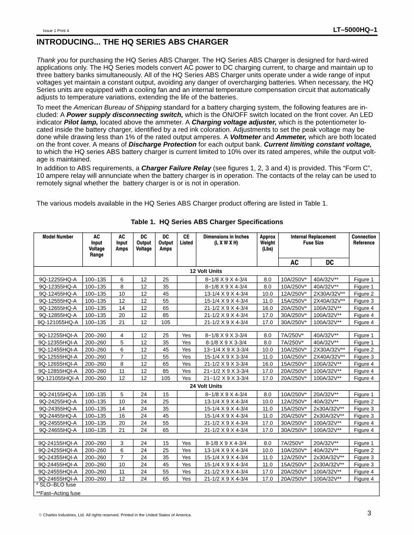
The various models available in the HQ Series ABS Charger product offering are listed in Table 1.
Table 1. HQ Series ABS Charger Specifications
Model Number ACInput
VoltageRange
ACInputAmps
DCOutputVoltage
DCOutputAmps
CEListed
Dimensions in Inches(L X W X H)
ApproxWeight(Lbs)
Internal ReplacementFuse Size
ConnectionReference
AC DC
12 Volt Units
9Q-12255HQ-A 100–135 6 12 25 8−1/8 X 9 X 4-3/4 8.0 10A/250V* 40A/32V** Figure 19Q-12355HQ-A 100–135 8 12 35 8−1/8 X 9 X 4-3/4 8.0 10A/250V* 40A/32V** Figure 19Q-12455HQ-A 100–135 10 12 45 13-1/4 X 9 X 4-3/4 10.0 12A/250V* 2X30A/32V** Figure 29Q-12555HQ-A 100–135 12 12 55 15-1/4 X 9 X 4-3/4 11.0 15A/250V* 2X40A/32V** Figure 39Q-12655HQ-A 100–135 14 12 65 21-1/2 X 9 X 4-3/4 16.0 20A/250V* 100A/32V** Figure 49Q-12855HQ-A 100–135 20 12 85 21-1/2 X 9 X 4-3/4 17.0 30A/250V* 100A/32V** Figure 49Q-121055HQ-A 100–135 21 12 105 21-1/2 X 9 X 4-3/4 17.0 30A/250V* 100A/32V** Figure 4
9Q-12255HQI-A 200–260 4 12 25 Yes 8−1/8 X 9 X 3-3/4 8.0 7A/250V* 40A/32V** Figure 19Q-12355HQI-A 200–260 5 12 35 Yes 8-1/8 X 9 X 3-3/4 8.0 7A/250V* 40A/32V** Figure 19Q-12455HQI-A 200–260 6 12 45 Yes 13−1/4 X 9 X 3-3/4 10.0 10A/250V* 2X30A/32V** Figure 29Q-12555HQI-A 200–260 7 12 55 Yes 15-1/4 X 9 X 3-3/4 11.0 10A/250V* 2X40A/32V** Figure 39Q-12655HQI-A 200–260 8 12 65 Yes 21-1/2 X 9 X 3-3/4 16.0 15A/250V* 100A/32V** Figure 49Q-12855HQI-A 200–260 11 12 85 Yes 21−1/2 X 9 X 3-3/4 17.0 20A/250V* 100A/32V** Figure 49Q-121055HQI-A 200–260 12 12 105 Yes 21−1/2 X 9 X 3-3/4 17.0 20A/250V* 100A/32V** Figure 4
24 Volt Units
9Q-24155HQ-A 100–135 5 24 15 8−1/8 X 9 X 4-3/4 8.0 10A/250V* 20A/32V** Figure 19Q-24255HQ-A 100–135 10 24 25 13-1/4 X 9 X 4-3/4 10.0 12A/250V* 40A/32V** Figure 29Q-24355HQ-A 100–135 14 24 35 15-1/4 X 9 X 4-3/4 11.0 15A/250V* 2x30A/32V** Figure 39Q-24455HQ-A 100–135 16 24 45 15-1/4 X 9 X 4-3/4 11.0 20A/250V* 2x30A/32V** Figure 39Q-24555HQ-A 100–135 20 24 55 21-1/2 X 9 X 4-3/4 17.0 30A/250V* 100A/32V** Figure 49Q-24655HQ-A 100–135 21 24 65 21-1/2 X 9 X 4-3/4 17.0 30A/250V* 100A/32V** Figure 4
9Q-24155HQI-A 200–260 3 24 15 Yes 8-1/8 X 9 X 4-3/4 8.0 7A/250V* 20A/32V** Figure 19Q-24255HQI-A 200–260 6 24 25 Yes 13-1/4 X 9 X 4-3/4 10.0 10A/250V* 40A/32V** Figure 29Q-24355HQI-A 200–260 7 24 35 Yes 15-1/4 X 9 X 4-3/4 11.0 12A/250V* 2x30A/32V** Figure 39Q-24455HQI-A 200–260 10 24 45 Yes 15-1/4 X 9 X 4-3/4 11.0 15A/250V* 2x30A/32V** Figure 39Q-24555HQI-A 200–260 11 24 55 Yes 21-1/2 X 9 X 4-3/4 17.0 20A/250V* 100A/32V** Figure 49Q-24655HQI-A 200–260 12 24 65 Yes 21-1/2 X 9 X 4-3/4 17.0 20A/250V* 100A/32V** Figure 4
* SLO–BLO fuse
**Fast–Acting fuse
LT–5000HQ–1 Issue 1 Print 4
4 � Charles Industries, Ltd. All rights reserved. Printed in the United States of America.
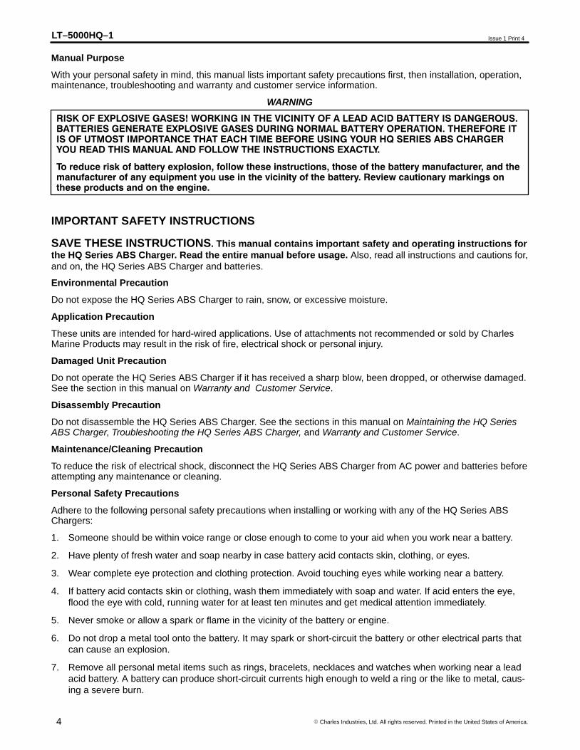
Manual Purpose
With your personal safety in mind, this manual lists important safety precautions first, then installation, operation,maintenance, troubleshooting and warranty and customer service information.
RISK OF EXPLOSIVE GASES! WORKING IN THE VICINITY OF A LEAD ACID BATTERY IS DANGEROUS.BATTERIES GENERATE EXPLOSIVE GASES DURING NORMAL BATTERY OPERATION. THEREFORE ITIS OF UTMOST IMPORTANCE THAT EACH TIME BEFORE USING YOUR HQ SERIES ABS CHARGERYOU READ THIS MANUAL AND FOLLOW THE INSTRUCTIONS EXACTLY.
To reduce risk of battery explosion, follow these instructions, those of the battery manufacturer, and themanufacturer of any equipment you use in the vicinity of the battery. Review cautionary markings onthese products and on the engine.
WARNING
IMPORTANT SAFETY INSTRUCTIONS
SAVE THESE INSTRUCTIONS. This manual contains important safety and operating instructions forthe HQ Series ABS Charger. Read the entire manual before usage. Also, read all instructions and cautions for,and on, the HQ Series ABS Charger and batteries.
Environmental Precaution
Do not expose the HQ Series ABS Charger to rain, snow, or excessive moisture.
Application Precaution
These units are intended for hard-wired applications. Use of attachments not recommended or sold by CharlesMarine Products may result in the risk of fire, electrical shock or personal injury.
Damaged Unit Precaution
Do not operate the HQ Series ABS Charger if it has received a sharp blow, been dropped, or otherwise damaged.See the section in this manual on Warranty and Customer Service.
Disassembly Precaution
Do not disassemble the HQ Series ABS Charger. See the sections in this manual on Maintaining the HQ SeriesABS Charger, Troubleshooting the HQ Series ABS Charger, and Warranty and Customer Service.
Maintenance/Cleaning Precaution
To reduce the risk of electrical shock, disconnect the HQ Series ABS Charger from AC power and batteries beforeattempting any maintenance or cleaning.
Personal Safety Precautions
Adhere to the following personal safety precautions when installing or working with any of the HQ Series ABSChargers:
1. Someone should be within voice range or close enough to come to your aid when you work near a battery.
2. Have plenty of fresh water and soap nearby in case battery acid contacts skin, clothing, or eyes.
3. Wear complete eye protection and clothing protection. Avoid touching eyes while working near a battery.
4. If battery acid contacts skin or clothing, wash them immediately with soap and water. If acid enters the eye,flood the eye with cold, running water for at least ten minutes and get medical attention immediately.
5. Never smoke or allow a spark or flame in the vicinity of the battery or engine.
6. Do not drop a metal tool onto the battery. It may spark or short-circuit the battery or other electrical parts thatcan cause an explosion.
7. Remove all personal metal items such as rings, bracelets, necklaces and watches when working near a leadacid battery. A battery can produce short-circuit currents high enough to weld a ring or the like to metal, caus-ing a severe burn.

LT–5000HQ–1Issue 1 Print 4
5� Charles Industries, Ltd. All rights reserved. Printed in the United States of America.
8. Do not use the HQ Series ABS Charger for charging dry cell batteries that are commonly used with consumerand home appliances. These batteries may burst and cause personal injury and property damage.
9. NEVER charge a frozen battery.
CAUTION
DO NOT attempt to charge multiple or non-recommended cell types. Other types of batteries may burst,causing personal injury and damage.
Preparing to Charge Precautions
Before charging a battery with the HQ Series ABS Charger, read the following precautions:
1. Make sure all accessories in the boat are off.
2. If the battery must be removed from the boat, always remove the grounded terminal from the battery first.
3. Be sure the area around the battery is well ventilated while the battery is being charged. Vapors can be force-fully blown away using a piece of cardboard or other non-metallic material as a “hand fan”.
4. Clean battery terminals. Be careful to keep corrosion from coming in contact with eyes.
5. For “flooded” batteries, add distilled water in each cell until battery acid reaches levels specified by the batterymanufacturer. Do not overfill!
6. For “sealed” batteries, carefully follow the manufacturer’s recharging instructions.
7. Study all battery manufacturer precautions, such as removing or not removing cell caps while charging andrecommended rates of charge.
Connecting to the Battery Outside the Boat Precaution
The HQ Series ABS Chargers have been specifically designed for hard-wired marine use inside a boat. They arenot designed or equipped for charging batteries on shore or outside a boat.
Grounding Precautions
1. The HQ Series ABS Charger should be connected to a grounded, permanent wiring system, at the equipmentgrounding (GRN) terminal on the HQ Series ABS Charger.
2. Connections to the HQ Series ABS Charger should comply with all local codes and ordinances.
External connections to the HQ Series ABS Charger shall comply with the U.S. Coast Guard ElectricalRegulations (33CFR183 subpart I).
WARNING
INSTALLING THE HQ Series ABS Charger
Note: Read this manual and all precautions before installing or making connections!
Verifying Proper Battery/Charger Type
The HQ Series ABS Charger models may be used for charging many battery types. All HQ Series ABS Chargershave been factory preset to a “Bulk” peak voltage of 14.5vdc/29.0vdc and a “Float” peak voltage of13.6vdc/27.2vdc (typical for Lead Acid/Flooded batteries).To adjust for a different DC output voltage or battery celltype, refer to Figures 1 through 4 to locate the “OUTPUT ADJUSTMENT POTENTIOMETER”.� Disconnect all batteries and apply a load of less than 1 ampere.
� Connect a DC voltmeter from the DC NEG output terminal and to any one of the DC POS output terminals
� Apply the proper AC input voltage and adjust the OUTPUT ADJUSTMENT POTENTIOMETER to the desired peak “Bulk” voltage.
Note: The “Float” voltage will adjust simultaneously with the “Bulk” voltage
LT–5000HQ–1 Issue 1 Print 4
6 � Charles Industries, Ltd. All rights reserved. Printed in the United States of America.
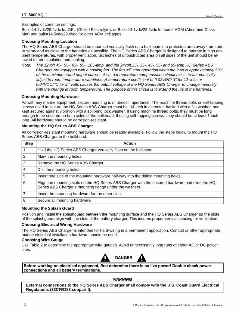
Examples of common settings:Bulk=14.2vdc/28.4vdc for GEL (Gelled Electrolyte), or Bulk=14.1vdc/28.2vdc for some AGM (Absorbed GlassMat) and bulk=14.5vdc/29.0vdc for other AGM cell types.
Choosing Mounting LocationThe HQ Series ABS Charger should be mounted vertically flush on a bulkhead in a protected area away from rainor spray and as close to the batteries as possible. The HQ Series ABS Charger is designed to operate in high am-bient temperatures, with proper ventilation. Six inches of unobstructed area on all sides of the unit should be al-lowed for air circulation and cooling.Note: The 12volt 45-, 55-, 65-, 85-, 105-amp, and the 24volt 25-, 35-, 45-, 55- and 65-amp HQ Series ABS
Chargers are equipped with a cooling fan. The fan will start operation when the load is approximately 50%of the maximum rated output current. Also, a temperature compensation circuit exists to automaticallyadjust to room temperature variations. A temperature coefficient of 0.02VDC/�C for 12 volts or0.04VDC/�C for 24 volts causes the output voltage of the HQ Series ABS Charger to change inverselywith the change in room temperature. The purpose of this circuit is to extend the life of the batteries.
Choosing Mounting HardwareAs with any marine equipment, secure mounting is of utmost importance. The machine thread bolts or self-tappingscrews used to secure the HQ Series ABS Charger must be 1/4-inch in diameter, backed with a flat washer, andkept secured against vibration with a split-ring lock washer. If using machine thread bolts, they must be longenough to be secured on both sides of the bulkhead. If using self-tapping screws, they should be at least 1 inchlong. All hardware should be corrosion-resistant.
Mounting the HQ Series ABS Charger
All corrosion-resistant mounting hardware should be readily available. Follow the steps below to mount the HQSeries ABS Charger to the bulkhead.
Step Action
1. Hold the HQ Series ABS Charger vertically flush on the bulkhead.
2. Mark the mounting holes.
3. Remove the HQ Series ABS Charger.
4. Drill the mounting holes.
5. Insert one side of the mounting hardware half-way into the drilled mounting holes.
6. Align the mounting slots on the HQ Series ABS Charger with the secured hardware and slide the HQSeries ABS Charger’s mounting flange under the washers.
7. Insert the mounting hardware for the other side.
8. Secure all mounting hardware.
Mounting the Splash GuardPosition and install the splashguard between the mounting surface and the HQ Series ABS Charger so the slotsof the splashguard align with the slots of the battery charger. This insures proper vertical spacing for ventilation.
Choosing Electrical Wiring HardwareThe HQ Series ABS Charger is intended for hard-wiring in a permanent application. Conduit or other appropriatemarine electrical installation hardware should be used.Choosing Wire GaugeUse Table 2 to determine the appropriate wire gauges. Avoid unnecessarily long runs of either AC or DC powerlines.
Before working on electrical equipment, first determine there is no live power! Double check powerconnections and all battery terminations.
DANGER
External connections to the HQ Series ABS Charger shall comply with the U.S. Coast Guard ElectricalRegulations (33CFR183 subpart I).
WARNING
LT–5000HQ–1Issue 1 Print 4
7� Charles Industries, Ltd. All rights reserved. Printed in the United States of America.
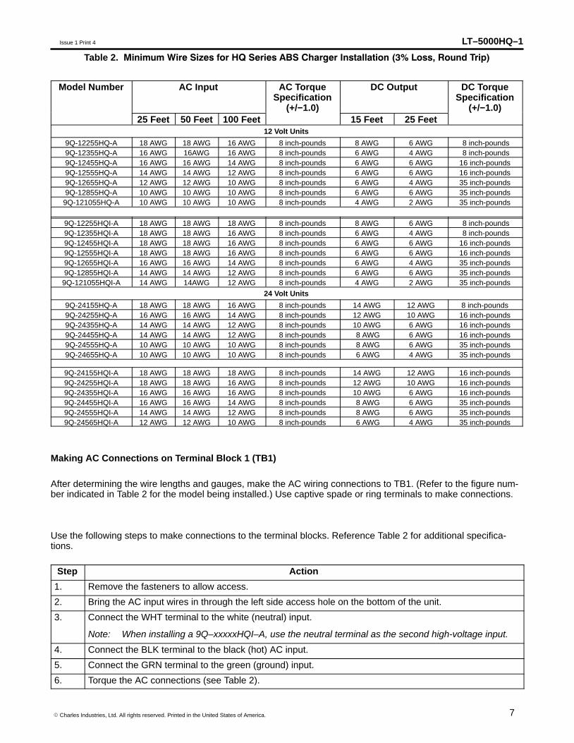
Table 2. Minimum Wire Sizes for HQ Series ABS Charger Installation (3% Loss, Round Trip)
Model Number AC Input AC TorqueSpecification
(+/−1.0)
DC Output DC TorqueSpecification
(+/−1.0)25 Feet 50 Feet 100 Feet 15 Feet 25 Feet
12 Volt Units
9Q-12255HQ-A 18 AWG 18 AWG 16 AWG 8 inch-pounds 8 AWG 6 AWG 8 inch-pounds9Q-12355HQ-A 16 AWG 16AWG 16 AWG 8 inch-pounds 6 AWG 4 AWG 8 inch-pounds9Q-12455HQ-A 16 AWG 16 AWG 14 AWG 8 inch-pounds 6 AWG 6 AWG 16 inch-pounds9Q-12555HQ-A 14 AWG 14 AWG 12 AWG 8 inch-pounds 6 AWG 6 AWG 16 inch-pounds9Q-12655HQ-A 12 AWG 12 AWG 10 AWG 8 inch-pounds 6 AWG 4 AWG 35 inch-pounds9Q-12855HQ-A 10 AWG 10 AWG 10 AWG 8 inch-pounds 6 AWG 6 AWG 35 inch-pounds9Q-121055HQ-A 10 AWG 10 AWG 10 AWG 8 inch-pounds 4 AWG 2 AWG 35 inch-pounds
9Q-12255HQI-A 18 AWG 18 AWG 18 AWG 8 inch-pounds 8 AWG 6 AWG 8 inch-pounds9Q-12355HQI-A 18 AWG 18 AWG 16 AWG 8 inch-pounds 6 AWG 4 AWG 8 inch-pounds9Q-12455HQI-A 18 AWG 18 AWG 16 AWG 8 inch-pounds 6 AWG 6 AWG 16 inch-pounds9Q-12555HQI-A 18 AWG 18 AWG 16 AWG 8 inch-pounds 6 AWG 6 AWG 16 inch-pounds9Q-12655HQI-A 16 AWG 16 AWG 14 AWG 8 inch-pounds 6 AWG 4 AWG 35 inch-pounds9Q-12855HQI-A 14 AWG 14 AWG 12 AWG 8 inch-pounds 6 AWG 6 AWG 35 inch-pounds9Q-121055HQI-A 14 AWG 14AWG 12 AWG 8 inch-pounds 4 AWG 2 AWG 35 inch-pounds
24 Volt Units
9Q-24155HQ-A 18 AWG 18 AWG 16 AWG 8 inch-pounds 14 AWG 12 AWG 8 inch-pounds9Q-24255HQ-A 16 AWG 16 AWG 14 AWG 8 inch-pounds 12 AWG 10 AWG 16 inch-pounds9Q-24355HQ-A 14 AWG 14 AWG 12 AWG 8 inch-pounds 10 AWG 6 AWG 16 inch-pounds9Q-24455HQ-A 14 AWG 14 AWG 12 AWG 8 inch-pounds 8 AWG 6 AWG 16 inch-pounds9Q-24555HQ-A 10 AWG 10 AWG 10 AWG 8 inch-pounds 8 AWG 6 AWG 35 inch-pounds9Q-24655HQ-A 10 AWG 10 AWG 10 AWG 8 inch-pounds 6 AWG 4 AWG 35 inch-pounds
9Q-24155HQI-A 18 AWG 18 AWG 18 AWG 8 inch-pounds 14 AWG 12 AWG 16 inch-pounds9Q-24255HQI-A 18 AWG 18 AWG 16 AWG 8 inch-pounds 12 AWG 10 AWG 16 inch-pounds9Q-24355HQI-A 16 AWG 16 AWG 16 AWG 8 inch-pounds 10 AWG 6 AWG 16 inch-pounds9Q-24455HQI-A 16 AWG 16 AWG 14 AWG 8 inch-pounds 8 AWG 6 AWG 35 inch-pounds9Q-24555HQI-A 14 AWG 14 AWG 12 AWG 8 inch-pounds 8 AWG 6 AWG 35 inch-pounds9Q-24565HQI-A 12 AWG 12 AWG 10 AWG 8 inch-pounds 6 AWG 4 AWG 35 inch-pounds
Making AC Connections on Terminal Block 1 (TB1)
After determining the wire lengths and gauges, make the AC wiring connections to TB1. (Refer to the figure num-ber indicated in Table 2 for the model being installed.) Use captive spade or ring terminals to make connections.
Use the following steps to make connections to the terminal blocks. Reference Table 2 for additional specifica-tions.
Step Action
1. Remove the fasteners to allow access.
2. Bring the AC input wires in through the left side access hole on the bottom of the unit.
3. Connect the WHT terminal to the white (neutral) input.
Note: When installing a 9Q–xxxxxHQI–A, use the neutral terminal as the second high-voltage input.
4. Connect the BLK terminal to the black (hot) AC input.
5. Connect the GRN terminal to the green (ground) input.
6. Torque the AC connections (see Table 2).
LT–5000HQ–1 Issue 1 Print 4
8 � Charles Industries, Ltd. All rights reserved. Printed in the United States of America.
Do not operate this unit without the green wire connected to the HQ Series ABS Charger and to asuitable ground connection.
DANGER
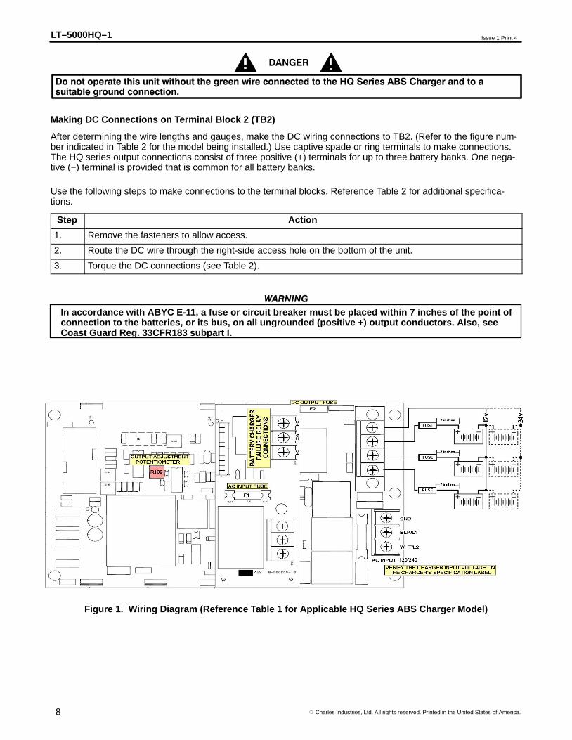
Making DC Connections on Terminal Block 2 (TB2)
After determining the wire lengths and gauges, make the DC wiring connections to TB2. (Refer to the figure num-ber indicated in Table 2 for the model being installed.) Use captive spade or ring terminals to make connections.The HQ series output connections consist of three positive (+) terminals for up to three battery banks. One nega-tive (−) terminal is provided that is common for all battery banks.
Use the following steps to make connections to the terminal blocks. Reference Table 2 for additional specifica-tions.
Step Action
1. Remove the fasteners to allow access.
2. Route the DC wire through the right-side access hole on the bottom of the unit.
3. Torque the DC connections (see Table 2).
In accordance with ABYC E-11, a fuse or circuit breaker must be placed within 7 inches of the point ofconnection to the batteries, or its bus, on all ungrounded (positive +) output conductors. Also, seeCoast Guard Reg. 33CFR183 subpart I.
WARNING
Figure 1. Wiring Diagram (Reference Table 1 for Applicable HQ Series ABS Charger Model)
LT–5000HQ–1Issue 1 Print 4
9� Charles Industries, Ltd. All rights reserved. Printed in the United States of America.
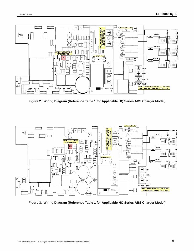
Figure 2. Wiring Diagram (Reference Table 1 for Applicable HQ Series ABS Charger Model)
Figure 3. Wiring Diagram (Reference Table 1 for Applicable HQ Series ABS Charger Model)
LT–5000HQ–1 Issue 1 Print 4
10 � Charles Industries, Ltd. All rights reserved. Printed in the United States of America.
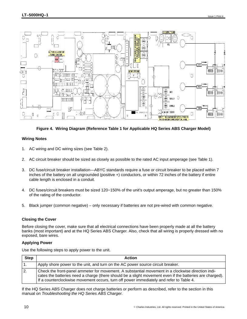
Figure 4. Wiring Diagram (Reference Table 1 for Applicable HQ Series ABS Charger Model)
Wiring Notes
1. AC wiring and DC wiring sizes (see Table 2).
2. AC circuit breaker should be sized as closely as possible to the rated AC input amperage (see Table 1).
3. DC fuse/circuit breaker installation—ABYC standards require a fuse or circuit breaker to be placed within 7inches of the battery on all ungrounded (positive +) conductors, or within 72 inches of the battery if entirecable length is enclosed in a conduit.
4. DC fuses/circuit breakers must be sized 120−150% of the unit’s output amperage, but no greater than 150%of the rating of the conductor.
5. Black jumper (common negative) – only necessary if batteries are not pre-wired with common negative.
Closing the Cover
Before closing the cover, make sure that all electrical connections have been properly made at all the batterybanks (most important) and at the HQ Series ABS Charger. Also, check that all wiring is properly dressed with noexposed, bare wires.
Applying Power
Use the following steps to apply power to the unit.
Step Action
1. Apply shore power to the unit, and turn on the AC power source circuit breaker.
2. Check the front-panel ammeter for movement. A substantial movement in a clockwise direction indi-cates the batteries need a charge (there should be a slight movement even if the batteries are charged).If a counterclockwise movement occurs, turn off power immediately and refer to Table 4.
If the HQ Series ABS Charger does not charge batteries or perform as described, refer to the section in thismanual on Troubleshooting the HQ Series ABS Charger.
LT–5000HQ–1Issue 1 Print 4
11� Charles Industries, Ltd. All rights reserved. Printed in the United States of America.
OPERATING THE HQ SERIES ABS CHARGER
Always follow all precautions in the IMPORTANT SAFETY INSTRUCTIONS section in this manual.
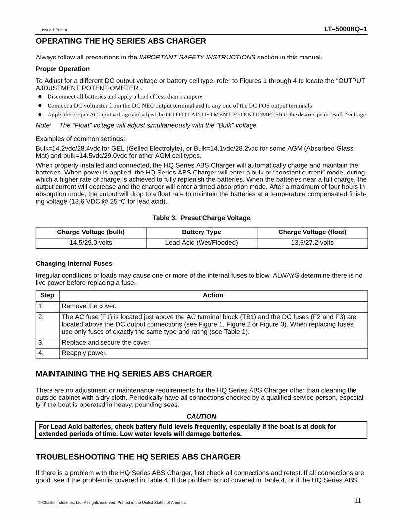
Proper Operation
To Adjust for a different DC output voltage or battery cell type, refer to Figures 1 through 4 to locate the “OUTPUTAJDUSTMENT POTENTIOMETER”.� Disconnect all batteries and apply a load of less than 1 ampere.
� Connect a DC voltmeter from the DC NEG output terminal and to any one of the DC POS output terminals
� Apply the proper AC input voltage and adjust the OUTPUT ADJUSTMENT POTENTIOMETER to the desired peak “Bulk” voltage.
Note: The “Float” voltage will adjust simultaneously with the “Bulk” voltage
Examples of common settings:
Bulk=14.2vdc/28.4vdc for GEL (Gelled Electrolyte), or Bulk=14.1vdc/28.2vdc for some AGM (Absorbed GlassMat) and bulk=14.5vdc/29.0vdc for other AGM cell types.
When properly installed and connected, the HQ Series ABS Charger will automatically charge and maintain thebatteries. When power is applied, the HQ Series ABS Charger will enter a bulk or “constant current” mode, duringwhich a higher rate of charge is achieved to fully replenish the batteries. When the batteries near a full charge, theoutput current will decrease and the charger will enter a timed absorption mode. After a maximum of four hours inabsorption mode, the output will drop to a float rate to maintain the batteries at a temperature compensated finish-ing voltage (13.6 VDC @ 25�C for lead acid).
Table 3. Preset Charge Voltage
Charge Voltage (bulk) Battery Type Charge Voltage (float)
14.5/29.0 volts Lead Acid (Wet/Flooded) 13.6/27.2 volts
Changing Internal Fuses
Irregular conditions or loads may cause one or more of the internal fuses to blow. ALWAYS determine there is nolive power before replacing a fuse.
Step Action
1. Remove the cover.
2. The AC fuse (F1) is located just above the AC terminal block (TB1) and the DC fuses (F2 and F3) arelocated above the DC output connections (see Figure 1, Figure 2 or Figure 3). When replacing fuses,use only fuses of exactly the same type and rating (see Table 1).
3. Replace and secure the cover.
4. Reapply power.
MAINTAINING THE HQ SERIES ABS CHARGER
There are no adjustment or maintenance requirements for the HQ Series ABS Charger other than cleaning theoutside cabinet with a dry cloth. Periodically have all connections checked by a qualified service person, especial-ly if the boat is operated in heavy, pounding seas.
CAUTION
For Lead Acid batteries, check battery fluid levels frequently, especially if the boat is at dock forextended periods of time. Low water levels will damage batteries.
TROUBLESHOOTING THE HQ SERIES ABS CHARGER
If there is a problem with the HQ Series ABS Charger, first check all connections and retest. If all connections aregood, see if the problem is covered in Table 4. If the problem is not covered in Table 4, or if the HQ Series ABS
LT–5000HQ–1 Issue 1 Print 4
12 � Charles Industries, Ltd. All rights reserved. Printed in the United States of America.
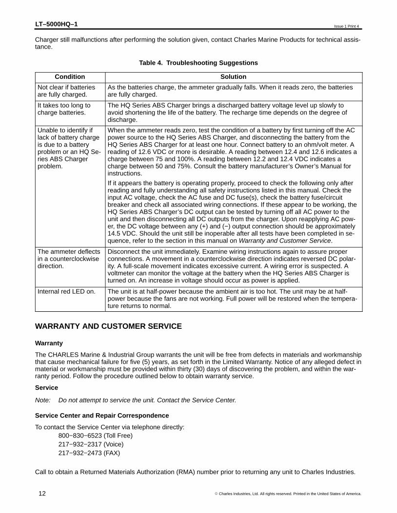
Charger still malfunctions after performing the solution given, contact Charles Marine Products for technical assis-tance.
Table 4. Troubleshooting Suggestions
Condition Solution
Not clear if batteriesare fully charged.
As the batteries charge, the ammeter gradually falls. When it reads zero, the batteriesare fully charged.
It takes too long tocharge batteries.
The HQ Series ABS Charger brings a discharged battery voltage level up slowly toavoid shortening the life of the battery. The recharge time depends on the degree ofdischarge.
Unable to identify iflack of battery chargeis due to a batteryproblem or an HQ Se-ries ABS Chargerproblem.
When the ammeter reads zero, test the condition of a battery by first turning off the ACpower source to the HQ Series ABS Charger, and disconnecting the battery from theHQ Series ABS Charger for at least one hour. Connect battery to an ohm/volt meter. Areading of 12.6 VDC or more is desirable. A reading between 12.4 and 12.6 indicates acharge between 75 and 100%. A reading between 12.2 and 12.4 VDC indicates acharge between 50 and 75%. Consult the battery manufacturer’s Owner’s Manual forinstructions.
If it appears the battery is operating properly, proceed to check the following only afterreading and fully understanding all safety instructions listed in this manual. Check theinput AC voltage, check the AC fuse and DC fuse(s), check the battery fuse/circuitbreaker and check all associated wiring connections. If these appear to be working, theHQ Series ABS Charger’s DC output can be tested by turning off all AC power to theunit and then disconnecting all DC outputs from the charger. Upon reapplying AC pow-er, the DC voltage between any (+) and (−) output connection should be approximately14.5 VDC. Should the unit still be inoperable after all tests have been completed in se-quence, refer to the section in this manual on Warranty and Customer Service.
The ammeter deflectsin a counterclockwisedirection.
Disconnect the unit immediately. Examine wiring instructions again to assure properconnections. A movement in a counterclockwise direction indicates reversed DC polar-ity. A full-scale movement indicates excessive current. A wiring error is suspected. Avoltmeter can monitor the voltage at the battery when the HQ Series ABS Charger isturned on. An increase in voltage should occur as power is applied.
Internal red LED on. The unit is at half-power because the ambient air is too hot. The unit may be at half-power because the fans are not working. Full power will be restored when the tempera-ture returns to normal.
WARRANTY AND CUSTOMER SERVICE
Warranty
The CHARLES Marine & Industrial Group warrants the unit will be free from defects in materials and workmanshipthat cause mechanical failure for five (5) years, as set forth in the Limited Warranty. Notice of any alleged defect inmaterial or workmanship must be provided within thirty (30) days of discovering the problem, and within the war-ranty period. Follow the procedure outlined below to obtain warranty service.
Service
Note: Do not attempt to service the unit. Contact the Service Center.
Service Center and Repair Correspondence
To contact the Service Center via telephone directly:800−830−6523 (Toll Free)217−932−2317 (Voice)217−932−2473 (FAX)
Call to obtain a Returned Materials Authorization (RMA) number prior to returning any unit to Charles Industries.

LT–5000HQ–1Issue 1 Print 4
13� Charles Industries, Ltd. All rights reserved. Printed in the United States of America.
Return the unit for repairs to the Service & Repair Center address below:Charles Industries, Ltd.Marine & Industrial Group503 NE 15th StreetCasey, IL 62420-2054USA
Correspondence can be sent to Corporate Headquarters via the address below:
Note: Do not return the unit to this address.
Charles Industries, Ltd.Marine & Industrial Group5600 Apollo DriveRolling Meadows, IL 60008-4049USA847−806−6300www.charlesindustries.com