isolation switch relays - clrwtr.com switch relays) are designed to be 100% compatible without the...
TRANSCRIPT
TURCKInterface Technology
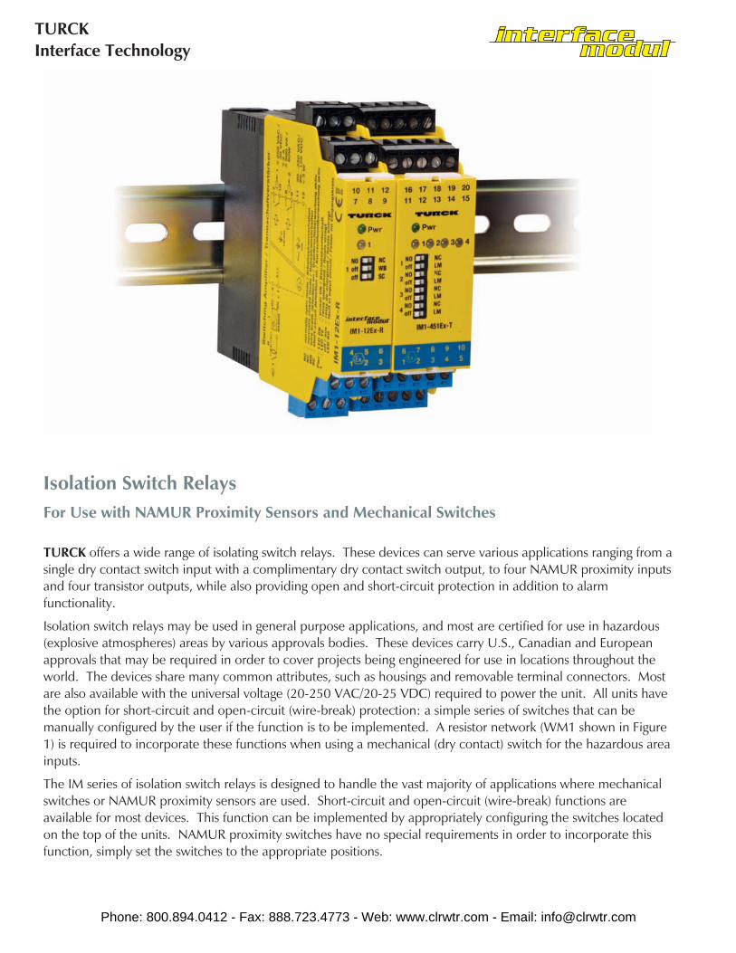
Isolation Switch RelaysFor Use with NAMUR Proximity Sensors and Mechanical Switches
TURCK offers a wide range of isolating switch relays. These devices can serve various applications ranging from asingle dry contact switch input with a complimentary dry contact switch output, to four NAMUR proximity inputsand four transistor outputs, while also providing open and short-circuit protection in addition to alarmfunctionality.
Isolation switch relays may be used in general purpose applications, and most are certified for use in hazardous(explosive atmospheres) areas by various approvals bodies. These devices carry U.S., Canadian and Europeanapprovals that may be required in order to cover projects being engineered for use in locations throughout theworld. The devices share many common attributes, such as housings and removable terminal connectors. Mostare also available with the universal voltage (20-250 VAC/20-25 VDC) required to power the unit. All units havethe option for short-circuit and open-circuit (wire-break) protection: a simple series of switches that can bemanually configured by the user if the function is to be implemented. A resistor network (WM1 shown in Figure1) is required to incorporate these functions when using a mechanical (dry contact) switch for the hazardous areainputs.
The IM series of isolation switch relays is designed to handle the vast majority of applications where mechanicalswitches or NAMUR proximity sensors are used. Short-circuit and open-circuit (wire-break) functions areavailable for most devices. This function can be implemented by appropriately configuring the switches locatedon the top of the units. NAMUR proximity switches have no special requirements in order to incorporate thisfunction, simply set the switches to the appropriate positions.
Phone: 800.894.0412 - Fax: 888.723.4773 - Web: www.clrwtr.com - Email: [email protected]

Interface ModuleApplication Guide
Dry contact (mechanical switches) however, require the use of a resistor network in order for the additionalfunctions to operate properly. The incorporation of a ready made resistor network module (WM1 see Figure 1) isrecommended.
This section highlights the devices and provides a simple approach for installing the various models available.Examples of common applications are provided along with simple connection diagrams that allow any user toeasily and safely install these devices.
Typical and specific functions for each individual device are highlighted in the "Features" portion of thespecification pages. A handy pin-out reference chart is also provided for each device. Input and output commonconfigurations for use with NAMUR proximity sensors and dry contact mechanical switches, are also highlightedin this section.
Common Input Configuration for Proximity SensorsNAMUR 2-wire proximity sensors are specifically designed to work with TURCK isolation switch relays. No entitycalculations are required, as all NAMUR proximity sensors and associated apparatus with NAMUR inputs (TURCKisolation switch relays) are designed to be 100% compatible without the requirement to calculate entityparameters. These calculations are accounted for in the design of both the field devices (proximity sensors) andthe interfaces (barriers). All NAMUR proximity sensors are compatible with NAMUR interface devices in allclassified areas.
The 2-wire configuration is standardized so the blue wire is always negative and the brown wire is always positive.Reversing these connections will not damage the device, however it will not function.
Connection diagrams for individual devices are shown in the product specification description pages.
Common Input Configurations for Dry Contact Mechanical SwitchesSimple switch inputs are easily accommodated by the NAMUR input interface units. Switches are not required tobe approved as intrinsically safe devices. Simple switches are defined as "simple apparatus" by the nationalelectrical code as: (NEC 504-2)A device that will neither generate nor store more than 1.2 V, 0.1 A, 25 mW, or 20 μ.
Using a simple switch does require the use of a resistor network (WM1) if the short-circuit and open-circuit(wire-break) functions are not used. These functions are not required and can be disabled by simply switchingthe function "OFF" using the configuration switches on the top of the units.
Figure 1
Phone: 800.894.0412 - Fax: 888.723.4773 - Web: www.clrwtr.com - Email: [email protected]

TURCKInterface Technology
Part number keys are to assist in IDENTIFICATION ONLY. Consult factory for catalog items not identified.
IM1-121Ex-RIsolation Switch RelayInterface ModuleSingle InputTwo Non-Hazardous Area Relay SwitchesOne Non-Hazardous Area Alarm SwitchIntrinsically Safe Associated ApparatusRelay Switch
IM1-22Ex-MTIsolation Switch RelayInterface ModuleTwo InputsTwo Non-Hazardous Area Relay SwitchesIntrinsically Safe Associated ApparatusMOSFET Switch
IM1-451Ex-TIsolation Switch RelayInterface ModuleFour InputsFive Non-Hazardous Area Relay SwitchesOne Non-Hazardous Area Alarm SwitchIntrinsically Safe Associated ApparatusTransistor Switch
Extension Examples:
Isolation Switch Relays Part Number Key
Interface Module
1 = Isolation Switch Relay
Function Group
Number of Inputs
IM 1 - 1 2 1 Ex - R
Intrinsically Safe Associated Apparatus
R =Relay SwitchT = Transistor SwitchMT= MOSFET Switch
Non-Hazardous Area Switching Circuits
Number of Non-Hazardous Area OutputsReflecting Hazardous Area Input Status
Number of Additional Non-Hazardous Area Alarm Outputs
Phone: 800.894.0412 - Fax: 888.723.4773 - Web: www.clrwtr.com - Email: [email protected]

Interface ModuleApplication Guide
All IM1-xxx Modules are Equipped With:
Intrinsically Safe Field TerminalsThis feature allows the use of any certified NAMUR sensor or dry contact mechanical switch (simple apparatus) tobe used in any area classification without risk of explosion.
Universal Input VoltageThis feature allows any power supply with an output of 20-250 VAC or 20-125 VDC to be used to power theunits. This provides extreme flexibility in the source power required to operate the units.
Removable "Keyed" TerminalsThis feature allows easy wiring. The keyed connectors assure safe and accurate installation. Terminals can beremoved and wired without physically making the connections in tight quarters. Cable harnesses that incorporatethese connectors can actually be wired outside cabinets, and assembly is completed by plugging in the terminalsto the corresponding barrier. A bus power configuration is also available. That allows several barrier's powerconnections to be bussed in a daisy-chain configuration, further reducing installation time and wiring.Replacement of units when necessary is also simplified.
Short-circuit and Open-circuit DetectionThis feature allows monitoring of field circuits for wire faults. The function is selectable and can be disabled if notrequired or desired. NAMUR sensors need no accessory to provide the function. Dry contact mechanicalswitches require a resistor network to properly function. The WM1 resistor network module will provide thisfunction, or a network of discrete resistors can be added by the user. Utilization of a common non-hazardousarea alarm circuit signifies a fault in the hazardous area wiring.
N.O./N.C. ConfigurationThis feature allows the input function to be selected as a normally open or normally closed output. Each channelcan be separately configured depending on module type.
Galvanic IsolationThis feature provides isolation between inputs, outputs and the power supply. In some cases, individual outputsare also isolated from each other.
Switching Status and Power Indication LEDsThis feature provides a visual indication for the switching status of each channel. The green LED indicates thatthe unit is powered. The dual color LEDs indicate switching (yellow) and fault status (red). A fault status on aninput disables the corresponding output relay.
Housing SizesThe size depends on the number of channels. All 4-channel devices utilize the wider 27 mm housing, while the1 and 2-channel devices are housed in the 18 mm style. Both are the same height, and can be mounted on aDIN-rail or flush mounted on a panel.
Phone: 800.894.0412 - Fax: 888.723.4773 - Web: www.clrwtr.com - Email: [email protected]
TURCKInterface Technology
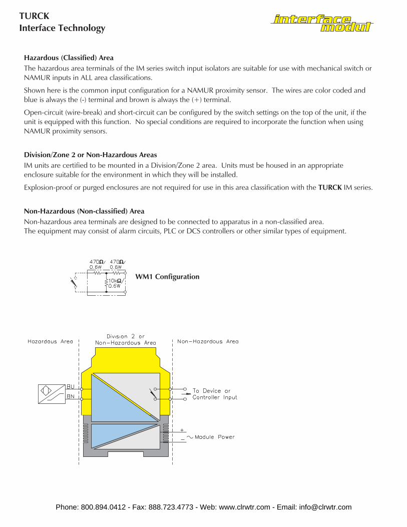
Hazardous (Classified) AreaThe hazardous area terminals of the IM series switch input isolators are suitable for use with mechanical switch orNAMUR inputs in ALL area classifications.
Shown here is the common input configuration for a NAMUR proximity sensor. The wires are color coded andblue is always the (-) terminal and brown is always the (+) terminal.
Open-circuit (wire-break) and short-circuit can be configured by the switch settings on the top of the unit, if theunit is equipped with this function. No special conditions are required to incorporate the function when usingNAMUR proximity sensors.
Division/Zone 2 or Non-Hazardous AreasIM units are certified to be mounted in a Division/Zone 2 area. Units must be housed in an appropriateenclosure suitable for the environment in which they will be installed.
Explosion-proof or purged enclosures are not required for use in this area classification with the TURCK IM series.
Non-Hazardous (Non-classified) AreaNon-hazardous area terminals are designed to be connected to apparatus in a non-classified area.The equipment may consist of alarm circuits, PLC or DCS controllers or other similar types of equipment.
WM1 Configuration
Phone: 800.894.0412 - Fax: 888.723.4773 - Web: www.clrwtr.com - Email: [email protected]

Interface ModuleApplication Guide
Phone: 800.894.0412 - Fax: 888.723.4773 - Web: www.clrwtr.com - Email: [email protected]
TURCKInterface Technology
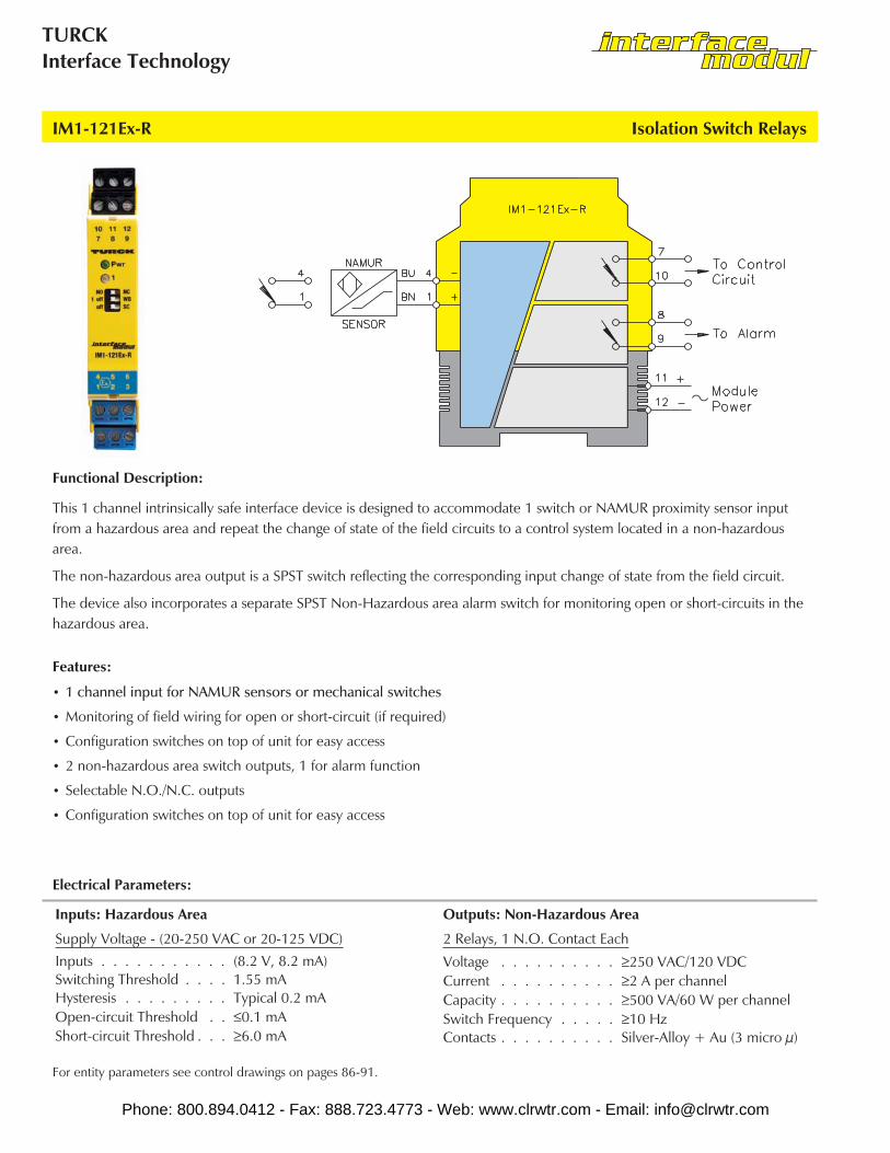
This 1 channel intrinsically safe interface device is designed to accommodate 1 switch or NAMUR proximity sensor inputfrom a hazardous area and repeat the change of state of the field circuits to a control system located in a non-hazardousarea.
The non-hazardous area output is a SPST switch reflecting the corresponding input change of state from the field circuit.
The device also incorporates a separate SPST Non-Hazardous area alarm switch for monitoring open or short-circuits in thehazardous area.
Functional Description:
• 1 channel input for NAMUR sensors or mechanical switches
• Monitoring of field wiring for open or short-circuit (if required)
• Configuration switches on top of unit for easy access
• 2 non-hazardous area switch outputs, 1 for alarm function
• Selectable N.O./N.C. outputs
• Configuration switches on top of unit for easy access
Features:
IM1-121Ex-R Isolation Switch Relays
Inputs: Hazardous Area Outputs: Non-Hazardous Area
Supply Voltage - (20-250 VAC or 20-125 VDC)Inputs . . . . . . . . . . . (8.2 V, 8.2 mA)Switching Threshold . . . . 1.55 mAHysteresis . . . . . . . . . Typical 0.2 mAOpen-circuit Threshold . . ≤0.1 mAShort-circuit Threshold . . . ≥6.0 mA
2 Relays, 1 N.O. Contact Each
Voltage . . . . . . . . . . ≥250 VAC/120 VDCCurrent . . . . . . . . . . ≥2 A per channelCapacity . . . . . . . . . . ≥500 VA/60 W per channelSwitch Frequency . . . . . ≥10 HzContacts . . . . . . . . . . Silver-Alloy + Au (3 micro µ)
Electrical Parameters:
For entity parameters see control drawings on pages 86-91.
Phone: 800.894.0412 - Fax: 888.723.4773 - Web: www.clrwtr.com - Email: [email protected]

Interface ModuleApplication Guide
Isolation Switch Relays IM1-121Ex-R
Pin # Terminal Function
1 (+) to Field Device
2 No Connection
3 No Connection
4 (-) to Field Device
5 No Connection
6 No Connection
7 Non-Hazardous Area Switch #1
8 Non-Hazardous Area Switch #2 Alarm
9 Non-Hazardous Area Switch #2 Alarm
10 Non-Hazardous Area Switch #1
11 Module Power (+) or AC
12 Module Power (-) or AC
Phone: 800.894.0412 - Fax: 888.723.4773 - Web: www.clrwtr.com - Email: [email protected]

TURCKInterface Technology
IM1-121Ex-T Isolation Switch Relays
This 1 channel intrinsically safe interface device is designed to accommodate 1 switch or NAMUR proximity sensor inputfrom a hazardous area and repeat the change of state of the field circuits to a control system located in a non-hazardousarea.
The non-hazardous area output is a NPN Transistor reflecting the corresponding input change of state from the field circuitwhen properly configured.
Functional Description:
• 1 channel input for NAMUR sensors or mechanical switches
• Monitoring of field wiring for open or short-circuit (if required)
• Configuration switches on top of unit for easy access
• 2 isolated short-circuit protected non-hazardous area NPN transistor outputs, 1 for alarm function
• Selectable N.O./N.C. outputs
• Configuration switches on top of unit for easy access
Features:
Inputs: Hazardous Area Outputs: Non-Hazardous Area
Supply Voltage - (20-250 VAC or 20-125 VDC)Inputs . . . . . . . . . . . (8.2 V, 8.2 mA)Switching Threshold . . . . 1.55 mAHysteresis . . . . . . . . . Typical 0.2 mAOpen-circuit Threshold . . ≤0.1 mAShort-circuit Threshold . . . ≥6.0 mA
2 Transistors, Potential Free Short-Circuit Protected
Switching Voltage . . . . . ≤30 VDCSwitch Current . . . . . . . ≤50 mA per channelSwitch Frequency . . . . . ≤5 kHzVoltage Drop. . . . . . . . ≤1.3 V
Electrical Parameters:
For entity parameters see control drawings on pages 86-91.
Phone: 800.894.0412 - Fax: 888.723.4773 - Web: www.clrwtr.com - Email: [email protected]

Interface ModuleApplication Guide
Isolation Switch Relays IM1-121Ex-T
Pin # Terminal Function
1 (+) to Field Device
2 No Connection
3 No Connection
4 (-) to Field Device
5 No Connection
6 No Connection
7 Non-Hazardous Area Transistor (+)
8 Non-Hazardous Area Trans Alarm (+)
9 Non-Hazardous Area Trans Alarm (-)
10 Non-Hazardous Area Transistor (-)
11 Module Power (+) or AC
12 Module Power (-) or AC
Phone: 800.894.0412 - Fax: 888.723.4773 - Web: www.clrwtr.com - Email: [email protected]

TURCKInterface Technology
IM1-22Ex-R Isolation Switch Relays
This 2 channel intrinsically safe interface device is designed to accommodate two switches or NAMUR proximity sensorinputs from a hazardous area and repeat the change of state of the field circuits to a control system located in anon-hazardous area.
The non-hazardous area outputs are two separate SPST switches reflecting the corresponding change of state from eachindividual input of the field circuit.
Functional Description:
• 2 channel input for NAMUR sensors or mechanical switches
• Monitoring of field wiring for open or short-circuit (if required)
• Configuration switches on top of unit for easy access
• 2 SPST non-hazardous area outputs; 1 for each channel
• Selectable N.O./N.C. outputs
• Configuration switches on top of unit for easy access
Features:
Inputs: Hazardous Area Outputs: Non-Hazardous Area
Supply Voltage - (20-250 VAC or 20-125 VDC)Inputs . . . . . . . . . . . (8.2 V, 8.2 mA)Switching Threshold . . . . 1.55 mAHysteresis . . . . . . . . . Typical 0.2 mAOpen-circuit Threshold . . ≤0.1 mAShort-circuit Threshold . . . ≥6.0 mA
2 Relays, 1 N.O. Contact Each
Voltage. . . . . . . . . . . ≥250 VAC/120 VDCCurrent . . . . . . . . . . ≥2 A per channelCapacity . . . . . . . . . . ≥500 VA / 60 W per channelSwitch Frequency . . . . . ≥10 HzContacts . . . . . . . . . . Silver-Alloy + Au (3 micro µ)
Electrical Parameters:
For entity parameters see control drawings on pages 86-91.
Phone: 800.894.0412 - Fax: 888.723.4773 - Web: www.clrwtr.com - Email: [email protected]
Interface ModuleApplication Guide
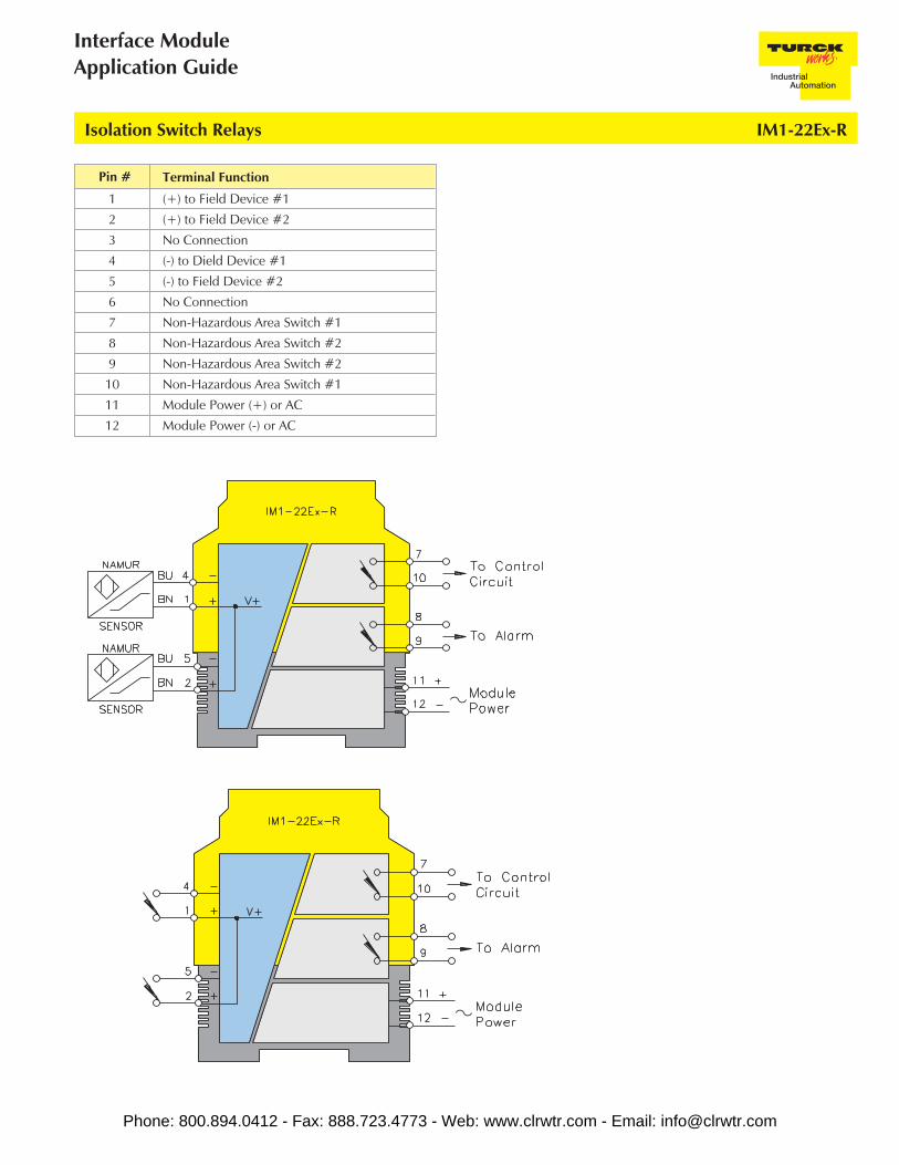
Isolation Switch Relays IM1-22Ex-R
Pin # Terminal Function
1 (+) to Field Device #1
2 (+) to Field Device #2
3 No Connection
4 (-) to Dield Device #1
5 (-) to Field Device #2
6 No Connection
7 Non-Hazardous Area Switch #1
8 Non-Hazardous Area Switch #2
9 Non-Hazardous Area Switch #2
10 Non-Hazardous Area Switch #1
11 Module Power (+) or AC
12 Module Power (-) or AC
Phone: 800.894.0412 - Fax: 888.723.4773 - Web: www.clrwtr.com - Email: [email protected]

TURCKInterface Technology
IM1-22Ex-T Isolation Switch Relays
This 2 channel intrinsically safe interface device is designed to accommodate two switches or NAMUR proximity sensorsinput from a hazardous area and repeat the change of state of the field circuits to a control system located in anon-hazardous area.
The non-hazardous area outputs are two separate NPN transistors reflecting the corresponding change of state from eachindividual input of the field circuit when properly configured.
Functional Description:
• 2 channel input for NAMUR sensors or mechanical switches
• Monitoring of field wiring for open or short-circuit (if required)
• Configuration switches on top of unit for easy access
• 2 isolated short-circuit protected NPN transistor non-hazardous area outputs; 1 for each channel
• Selectable N.O./N.C. outputs
• Configuration switches on top of unit for easy access
Features:
Inputs: Hazardous Area Outputs: Non-Hazardous Area
Supply Voltage - (20-250 VAC or 20-125 VDC)Inputs . . . . . . . . . . . (8.2 V, 8.2 mA)Switching Threshold . . . . 1.55 mAHysteresis . . . . . . . . . Typical 0.2 mAOpen-circuit Threshold . . ≤0.1 mAShort-circuit Threshold . . . ≥6.0 mA
2 Transistors, Potential Free Short-Circuit Protected
Switching Voltage . . . . . ≤30 VDCSwitch Current . . . . . . . ≤50 mA per channelSwitch Frequency . . . . . ≤5 kHzVoltage Drop. . . . . . . . ≤1.3 V
Electrical Parameters:
For entity parameters see control drawings on pages 86-91.
Phone: 800.894.0412 - Fax: 888.723.4773 - Web: www.clrwtr.com - Email: [email protected]

Interface ModuleApplication Guide
Isolation Switch Relays IM1-22Ex-T
Pin # Terminal Function
1 (+) to Field Device #1
2 (+) to Field Device #2
3 No Connection
4 (-) to Field Device #1
5 (-) to Field Device #2
6 No Connection
7 Non-Hazardous Area Transistor #1 (+)
8 Non-Hazardous Area Transistor #2 (+)
9 Non-Hazardous Area Transistor #2 (-)
10 Non-Hazardous Area Transistor #1 (-)
11 Module Power (+) or AC
12 Module Power (-) or AC
Phone: 800.894.0412 - Fax: 888.723.4773 - Web: www.clrwtr.com - Email: [email protected]

TURCKInterface Technology
IM1-22Ex-MT Isolation Switch Relays
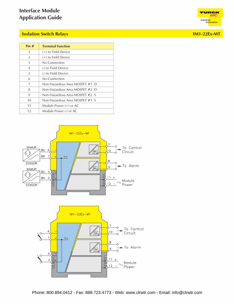
This 2 channel intrinsically safe interface device is designed to accommodate two switches or NAMUR proximity sensorsinput from a hazardous area and repeat the change of state of the field circuits to a control system located in anon-hazardous area.
The non-hazardous area outputs are two separate MOSFET transistors reflecting the corresponding change of state from eachindividual input of the field circuit when properly configured.
Functional Description:
• 2 channel input for NAMUR sensors or mechanical switches
• Monitoring of field wiring for open or short-circuit (if required)
• Configuration switches on top of unit for easy access
• 2 isolated non-hazardous area unipolar MOSFET outputs allow switching voltages up to 250 VAC at a maximum frequencyof 1 kHz, 1 for each channel
• Selectable N.O./N.C. outputs
• Configuration switches on top of unit for easy access
Features:
Inputs: Hazardous Area Outputs: Non-Hazardous Area
Supply Voltage - (20-250 VAC or 20-125 VDC)Inputs . . . . . . . . . . . (8.2 V, 8.2 mA)Switching Threshold . . . . 1.55 mAHysteresis . . . . . . . . . Typical 0.2 mAOpen Circuit Threshold . . ≤0.1 mAShort Circuit Threshold. . . ≥6.0 mA
2 MOSFET, Potential Free
Switching Voltage . . . . . ≥250 VAC/120 VDCSwitch Current . . . . . . . ≤90 mA per channelSwitch Capacity . . . . . . 22.5 VA/10.8 W per channelSwitch Capacity . . . . . . ≤1 kHz
Electrical Parameters:
For entity parameters see control drawings on pages 86-91.
Phone: 800.894.0412 - Fax: 888.723.4773 - Web: www.clrwtr.com - Email: [email protected]
Interface ModuleApplication Guide
Isolation Switch Relays IM1-22Ex-MT
Pin # Terminal Function
1 (+) to Field Device
2 (+) to Field Device
3 No Connection
4 (-) to Field Device
5 (-) to Field Device
6 No Connection
7 Non-Hazardous Area MOSFET #1 D
8 Non-Hazardous Area MOSFET #2 D
9 Non-Hazardous Area MOSFET #2 S
10 Non-Hazardous Area MOSFET #1 S
11 Module Power (+) or AC
12 Module Power (-) or AC
Phone: 800.894.0412 - Fax: 888.723.4773 - Web: www.clrwtr.com - Email: [email protected]
TURCKInterface Technology
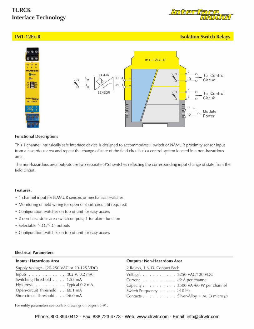
IM1-12Ex-R Isolation Switch Relays
This 1 channel intrinsically safe interface device is designed to accommodate 1 switch or NAMUR proximity sensor inputfrom a hazardous area and repeat the change of state of the field circuits to a control system located in a non-hazardousarea.
The non-hazardous area outputs are two separate SPST switches reflecting the corresponding input change of state from thefield circuit.
Functional Description:
• 1 channel input for NAMUR sensors or mechanical switches
• Monitoring of field wiring for open or short-circuit (if required)
• Configuration switches on top of unit for easy access
• 2 non-hazardous area switch outputs; 1 for alarm function
• Selectable N.O./N.C. outputs
• Configuration switches on top of unit for easy access
Features:
Inputs: Hazardous Area Outputs: Non-Hazardous Area
Supply Voltage - (20-250 VAC or 20-125 VDC)Inputs . . . . . . . . . . . (8.2 V, 8.2 mA)Switching Threshold . . . . 1.55 mAHysteresis . . . . . . . . . Typical 0.2 mAOpen-circuit Threshold . . ≤0.1 mAShor-circuit Threshold . . . ≥6.0 mA
2 Relays, 1 N.O. Contact Each
Voltage. . . . . . . . . . . ≥250 VAC/120 VDCCurrent . . . . . . . . . . ≥2 A per channelCapacity . . . . . . . . . . ≥500 VA /60 W per channelSwitch Frequency . . . . . ≥10 HzContacts . . . . . . . . . . Silver-Alloy + Au (3 micro µ)
Electrical Parameters:
For entity parameters see control drawings on pages 86-91.
Phone: 800.894.0412 - Fax: 888.723.4773 - Web: www.clrwtr.com - Email: [email protected]
Interface ModuleApplication Guide
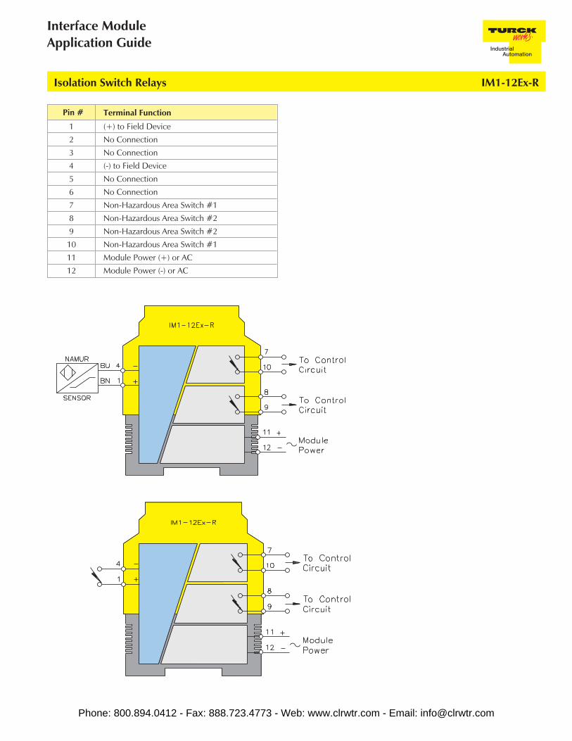
Isolation Switch Relays IM1-12Ex-R
Pin # Terminal Function
1 (+) to Field Device
2 No Connection
3 No Connection
4 (-) to Field Device
5 No Connection
6 No Connection
7 Non-Hazardous Area Switch #1
8 Non-Hazardous Area Switch #2
9 Non-Hazardous Area Switch #2
10 Non-Hazardous Area Switch #1
11 Module Power (+) or AC
12 Module Power (-) or AC
Phone: 800.894.0412 - Fax: 888.723.4773 - Web: www.clrwtr.com - Email: [email protected]
TURCKInterface Technology
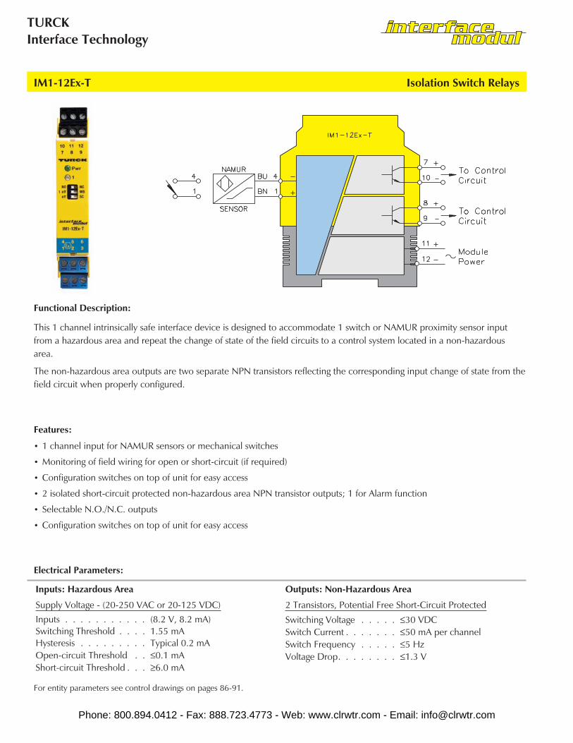
IM1-12Ex-T Isolation Switch Relays
This 1 channel intrinsically safe interface device is designed to accommodate 1 switch or NAMUR proximity sensor inputfrom a hazardous area and repeat the change of state of the field circuits to a control system located in a non-hazardousarea.
The non-hazardous area outputs are two separate NPN transistors reflecting the corresponding input change of state from thefield circuit when properly configured.
Functional Description:
• 1 channel input for NAMUR sensors or mechanical switches
• Monitoring of field wiring for open or short-circuit (if required)
• Configuration switches on top of unit for easy access
• 2 isolated short-circuit protected non-hazardous area NPN transistor outputs; 1 for Alarm function
• Selectable N.O./N.C. outputs
• Configuration switches on top of unit for easy access
Features:
Inputs: Hazardous Area Outputs: Non-Hazardous Area
Supply Voltage - (20-250 VAC or 20-125 VDC)Inputs . . . . . . . . . . . (8.2 V, 8.2 mA)Switching Threshold . . . . 1.55 mAHysteresis . . . . . . . . . Typical 0.2 mAOpen-circuit Threshold . . ≤0.1 mAShort-circuit Threshold . . . ≥6.0 mA
2 Transistors, Potential Free Short-Circuit Protected
Switching Voltage . . . . . ≤30 VDCSwitch Current . . . . . . . ≤50 mA per channelSwitch Frequency . . . . . ≤5 HzVoltage Drop. . . . . . . . ≤1.3 V
Electrical Parameters:
For entity parameters see control drawings on pages 86-91.
Phone: 800.894.0412 - Fax: 888.723.4773 - Web: www.clrwtr.com - Email: [email protected]

Interface ModuleApplication Guide
Isolation Switch Relays IM1-12Ex-T
Pin # Terminal Function
1 (+) to Field Device
2 No Connection
3 No Connection
4 (-) to Field Device
5 No Connection
6 No Connection
7 Non-Hazardous Area Transistor #1
8 Non-Hazardous Area Transistor #2
9 Non-Hazardous Area Transistor #2
10 Non-Hazardous Area Transistor #1
11 Module Power (+) or AC
12 Module Power (-) or AC
Phone: 800.894.0412 - Fax: 888.723.4773 - Web: www.clrwtr.com - Email: [email protected]

TURCKInterface Technology
IM1-12Ex-MT Isolation Switch Relays
This 1 channel intrinsically safe interface device is designed to accommodate 1 switch or NAMUR proximity sensor inputfrom a hazardous area and repeat the change of state of the field circuits to a control system located in a non-hazardousarea.
The non-hazardous area outputs are two separate MOSFET Transistors reflecting the corresponding input change of statefrom the field circuit when properly configured.
Functional Description:
• 1 channel input for NAMUR sensors or mechanical switches
• Monitoring of field wiring for open or short-circuit (if required)
• Configuration switches on top of unit for easy access
• 2 isolated non-hazardous area unipolar MOSFET outputs allow switching voltages up to 250 VACat a maximum frequency of 1 kHz
• Selectable N.O./N.C. outputs
• Configuration switches on top of unit for easy access
Features:
Inputs: Hazardous Area Outputs: Non-Hazardous Area
Supply Voltage - (20-250 VAC or 20-125 VDC)Inputs . . . . . . . . . . . (8.2 V, 8.2 mA)Switching Threshold . . . . 1.55 mAHysteresis . . . . . . . . . Typical 0.2 mAOpen-circuit Threshold . . ≤0.1 mAShort-circuit Threshold . . . ≥6.0 mA
2 MOSFET, Potential Free
Switch Current . . . . . . . ≤90 mA per channelSwitch Capacity . . . . . . 22.5 VA/10.8 W per channelSwitch Capacity . . . . . . ≤1 kHz
Electrical Parameters:
For entity parameters see control drawings on pages 86-91.
Phone: 800.894.0412 - Fax: 888.723.4773 - Web: www.clrwtr.com - Email: [email protected]

Interface ModuleApplication Guide
Isolation Switch Relays IM1-12Ex-MT
Pin # Terminal Function
1 (+) to Field Device
2 No Connection
3 No Connection
4 (-) to Field Device
5 No Connection
6 No Connection
7 Non-Hazardous Area MOSFET #1 D
8 Non-Hazardous Area MOSFET #2 D Alarm
9 Non-Hazardous Area MOSFET #2 S Alarm
10 Non-Hazardous Area MOSFET #1 S
11 Module Power (+) or AC
12 Module Power (-) or AC
Phone: 800.894.0412 - Fax: 888.723.4773 - Web: www.clrwtr.com - Email: [email protected]
TURCKInterface Technology
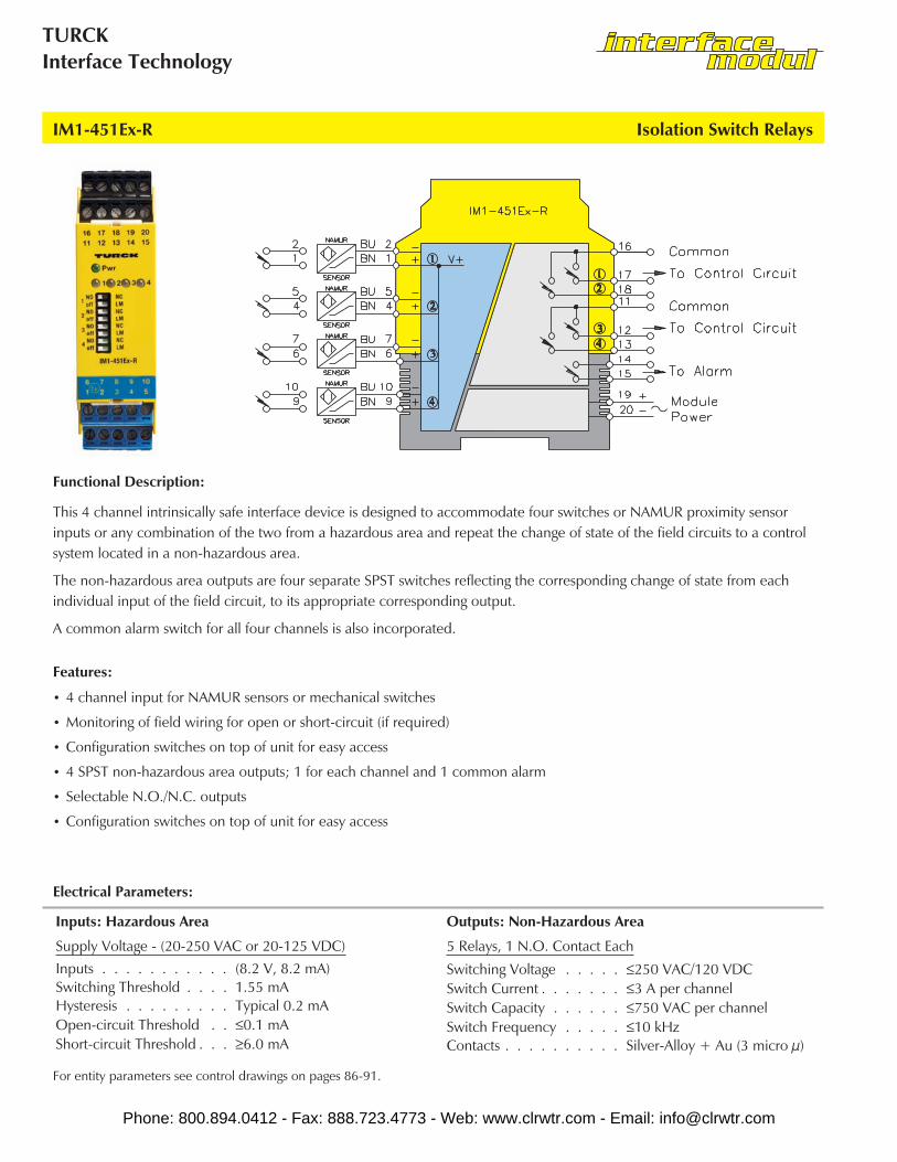
IM1-451Ex-R Isolation Switch Relays
This 4 channel intrinsically safe interface device is designed to accommodate four switches or NAMUR proximity sensorinputs or any combination of the two from a hazardous area and repeat the change of state of the field circuits to a controlsystem located in a non-hazardous area.
The non-hazardous area outputs are four separate SPST switches reflecting the corresponding change of state from eachindividual input of the field circuit, to its appropriate corresponding output.
A common alarm switch for all four channels is also incorporated.
Functional Description:
• 4 channel input for NAMUR sensors or mechanical switches
• Monitoring of field wiring for open or short-circuit (if required)
• Configuration switches on top of unit for easy access
• 4 SPST non-hazardous area outputs; 1 for each channel and 1 common alarm
• Selectable N.O./N.C. outputs
• Configuration switches on top of unit for easy access
Features:
Inputs: Hazardous Area Outputs: Non-Hazardous Area
Supply Voltage - (20-250 VAC or 20-125 VDC)Inputs . . . . . . . . . . . (8.2 V, 8.2 mA)Switching Threshold . . . . 1.55 mAHysteresis . . . . . . . . . Typical 0.2 mAOpen-circuit Threshold . . ≤0.1 mAShort-circuit Threshold . . . ≥6.0 mA
5 Relays, 1 N.O. Contact Each
Switching Voltage . . . . . ≤250 VAC/120 VDCSwitch Current . . . . . . . ≤3 A per channelSwitch Capacity . . . . . . ≤750 VAC per channelSwitch Frequency . . . . . ≤10 kHzContacts . . . . . . . . . . Silver-Alloy + Au (3 micro µ)
Electrical Parameters:
For entity parameters see control drawings on pages 86-91.
Phone: 800.894.0412 - Fax: 888.723.4773 - Web: www.clrwtr.com - Email: [email protected]

Interface ModuleApplication Guide
Isolation Switch Relays IM1-451Ex-R
Pin # Terminal Function
1 (+) to Field Device #1
2 (-) to Field Device #1
3 No Connection
4 (+) to Field Device #2
5 (-) to Field Device #2
6 (+) to Field Device #3
7 (-) to Field Device #3
8 No Connection
9 (+) to Field Device #4
10 (-) to Field Device #4
Pin # Terminal Function
11 Non-Hazardous Area Sw 3 & 4 common
12 Non-Hazardous Area Switch #3 (-)
13 Non-Hazardous Area Switch #4 (-)
14 Non-Hazardous Area Switch Alarm
15 Non-Hazardous Area Switch Alarm
16 Non-Hazardous Area Sw 1 & 2 common
17 Non-Hazardous Area Switch #1 (-)
18 Non-Hazardous Area Switch #2 (-)
19 Module Power (+) or AC
20 Module Power (-) or AC
Phone: 800.894.0412 - Fax: 888.723.4773 - Web: www.clrwtr.com - Email: [email protected]
TURCKInterface Technology
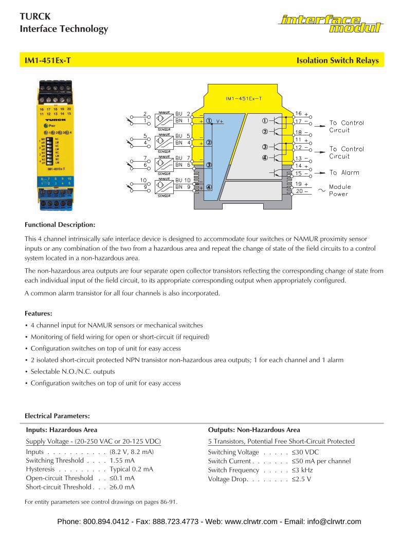
IM1-451Ex-T Isolation Switch Relays
This 4 channel intrinsically safe interface device is designed to accommodate four switches or NAMUR proximity sensorinputs or any combination of the two from a hazardous area and repeat the change of state of the field circuits to a controlsystem located in a non-hazardous area.
The non-hazardous area outputs are four separate open collector transistors reflecting the corresponding change of state fromeach individual input of the field circuit, to its appropriate corresponding output when appropriately configured.
A common alarm transistor for all four channels is also incorporated.
Functional Description:
• 4 channel input for NAMUR sensors or mechanical switches
• Monitoring of field wiring for open or short-circuit (if required)
• Configuration switches on top of unit for easy access
• 2 isolated short-circuit protected NPN transistor non-hazardous area outputs; 1 for each channel and 1 alarm
• Selectable N.O./N.C. outputs
• Configuration switches on top of unit for easy access
Features:
Inputs: Hazardous Area Outputs: Non-Hazardous Area
Supply Voltage - (20-250 VAC or 20-125 VDC)Inputs . . . . . . . . . . . (8.2 V, 8.2 mA)Switching Threshold . . . . 1.55 mAHysteresis . . . . . . . . . Typical 0.2 mAOpen-circuit Threshold . . ≤0.1 mAShort-circuit Threshold . . . ≥6.0 mA
5 Transistors, Potential Free Short-Circuit Protected
Switching Voltage . . . . . ≤30 VDCSwitch Current . . . . . . . ≤50 mA per channelSwitch Frequency . . . . . ≤3 kHzVoltage Drop. . . . . . . . ≤2.5 V
Electrical Parameters:
For entity parameters see control drawings on pages 86-91.
Phone: 800.894.0412 - Fax: 888.723.4773 - Web: www.clrwtr.com - Email: [email protected]

Interface ModuleApplication Guide
Isolation Switch Relays IM1-451Ex-T
Pin # Terminal Function
1 (+) to Field Device #1
2 (-) to Field Device #1
3 No Connection
4 (+) to Field Device #2
5 (-) to Field Device #2
6 (+) to Field Device #3
7 (-) to Field Device #3
8 No Connection
9 (+) to Field Device #4
10 (-) to Field Device #4
Pin # Terminal Function
11 (+) Non-Hazardous Area Trans 3 & 4
12 Non-Hazardous Area Transistor #3 (-)
13 Non-Hazardous Area Transistor #4 (-)
14 Non-Hazardous Area Trans Alarm (+)
15 Non-Hazardous Area Trans Alarm (-)
16 (+) Non-Hazardous Area Trans 1 & 2
17 Non-Hazardous Area Transistor #1 (-)
18 Non-Hazardous Area Transistor #2 (-)
19 Module Power (+) or AC
20 Module Power (-) or AC
Phone: 800.894.0412 - Fax: 888.723.4773 - Web: www.clrwtr.com - Email: [email protected]