iso 9001 : 2000 - novatek electronovatek-electro.com/docs/novatek-catalogue-en.pdf · protection...
TRANSCRIPT

INNOVATIVE CONTROLS, PROTECTION AND AUTOMATION SOLUTIONSN Electro
NOVATEK INDIA ENTERPRISES PVT. LTD.
PRODUCT CATALOGUE 2010
electrical circuit fault protection relaysinduction motor protection devices (SCADA)current overload relay and power limitersmultifunction timerstemperature controllers (SCADA)transformerless voltage stabilizersdata logging systems
Microprocessor based devices and relays

ISO 9001 : 2000

Dear Sirs, Wewouldliketothankyouforyourpatronageandinterestinoursphereofactivityandproducts.Thiscataloguecontainsinformationonnewdevelopmentsaswellasproductsthatyouarealreadyworkingwith. IthasbeenourconstantendeavortoemployhighestgradeprofessionalsinthefieldofResearch,DesignandManufactureofinnovativemicroprocessorbasedprotection,automationandcontroldevices.Ourcustomersarepeoplewhoprefersafetyinelectricaloperation,highlyefficientandreliableprotectionandcontrolsfortheirmachineryandequipment. Novatek-Electro Ltd. was established in one of themajor Ukrainian port city - Odessa in 1991with 100%Ukrainiancapital. Companyconsistsofhighlyexperiencedspecialistsinthefieldofengineeringinmicroprocessorbaseddevicesaswellasengineersofcontrolandsafeoperationofalltypesofelectriccircuitsandpowersystems.InadditionNovatek-ElectroLtd.hasnumberofresearchworkers,scientistswithPh.D.degree,researchengineersandspecialistsinpreciseelectronics,lasertechnology,etc.Thisallowsustodesignandmanufacturenewgenerationproductswithoutstandingreliabilityandfunctionality.SomeoftheproductsbyNovatek-ElectroLtd.havenoanaloguesandcouldbeconsideredatthelevelofscientificdiscoveries. ProductsandserviceswhichourCompanyprovidesthroughtheyearsgotverygoodrecognitionandarewidelyacknowledgedinUkraine,Russia,Belorussia,Kazakhstan,UzbekistanandotherCIScountries,CzechRepublic,Poland,Slovakia, LithuaniaandLatvia in theEuropeanUnion.Atpresentactive saleshas started in India,Pakistan,Kenya,Nigeria,VietnamandSouthAmerica(Argentina,CostaRica),etc. Ourcustomersandclientsrepresentwiderangeofindustrieswithvariedareasofapplicationsfortheinnovativesolutions and products that our company provides. There are big industrial plants, mines and energy generationcompanies, transport systems, refrigerationandair-conditioningcompanies, telecommunicationsandelectricpanelmanufacturersandpartiallyprivateandconsumer sector. Inanut-shellwearehonored tomentioncompanies likeMITTALSTEEL,ZAPOROZHSTAHL,SEVERSTAL–SteelPlant;MARIUPOLMETALLUGRICALPLANT;SEVGOKMINES;Majoroil companiesasLUKOIL,GAZPROM,FERGANAandASTUKREFINERYPLANTS; in telecommunicationssector–MTS,BEELINE,MEGAPHONEandothersasourvaluedcustomers. ProductsbyNovatek-ElectroLtd.areextremelyreliableandeffectivelyworkinalltypeofclimaticconditionsfromverylowtemperatureofdeepRussianNorthtohotandhumidclimateofIndiaandAfricancountries.
Wearecontinuouslyworkinghardonfurtherimprovementofourproductstheirfunctionalityandconsequentlydesignnewproducts intightcooperationwithourpartnersandcustomerstobringinnovativeandverycompetitiveproductsinthemarket.
Principleswhichwededicatedlyfolloware–reliability,functionality,highqualityandreasonable/affordableprice.Highreliabilityandquality isattainedwiththeuseofmostmoderntechniquesandtechnologiesonthebaseofmicroprocessors andmicrocontrollers. The assembly of products is being performedon the newest andmodernequipmentofknownandreputedbrands.Experiencedengineersandprogrammersareusingmostmodernsoftwaretoolsandprogramssetstocreateeasytoinstall,maintenancefreeSCADAcompatibledevices. Ourlongtermaimistorevolutionaliseautomationandcontrolindustrywithreadytouseaffordableequipments,whichcanbeusednotonlybytheGiantsofIndustrybutwouldalsofitthepocketsofSmall&Mediumscalesector.
YoursSincerely,Novatekmanagementteam.

The newest modification of a panel board mounted single phase voltage protection relay. Besides the principal dedication of protecting load against voltage surges in the mains, it provides a number of additional functions:
Multifunctional digital display;Operation mode selection by dip-
switchThe relay incorporates functions of 5
complete devices in one compact case:Combined OVER/UNDER-Voltage
protection relay with separate setting of Minimal and Maximal thresholds;
Minimum voltage protection relay;Maximum voltage protection relay;Protection from the consequences of neutral phase loss;Time delay - autoreclosing after the fault with user
defined time delay (protection from frequent starts or nuisance tripping);
Compact overall dimensions - 2-ways width casing.
Voltage relay for protection of a single-phase load against un-allowable mains voltage variations at currents of up to 32A. Quite often user face with the problem that the load exceeds 16A value admissible for standard voltage relays. To avoid additional costs connected with installation of a contactor into the panel board, the single-phase PH-102 voltage relay was designed for greater currents of up to 32A (7.0 kW), wall mounted immediately in the proximity of the load consuming equipment.
The relay is functionally similar to standard voltage relays for single phase voltage protection.
Single-phase voltage relaysAre used for the protection of single-phase loads, equipment and machiney against un-allowable
mains voltage drops and fluctuations as well as against the consequences of neutral line cut-off. They can be utilized either as independent switching devices, or as relays operating with a magnetic starter (contactor). Advantages of the relays are wide voltage operation range and broad range of adjustable parameters, including autoreclosing time delay settings for the protection of machinery and installations with long-term transient dynamics, like refrigeration and compressor units.
RN-113Voltage protection relay
in enclosure for standard DIN-rail mounting. Provides protection to any wattage loads: up to 7.0 kW – through its own changeover relay output contacts; over 7.0 kW (32A) – via contactor of appropriate rated power. To avoid fault tripping of the power load in case of minor and/or short-term undervoltage a fixed trip delay is envisaged, that is activated when minimal voltage level threshold (Umin) value is reached. The principle of measurement of "running mean" voltage value is being used in present product line and this ensures highest protection level with accuracy and reliability of operation.
RN-111M
Voltage protection "plug-socket" type relay, for regular household electronics and individual protection of single phase equipment and machinery with a standard power cord plug. Protection for single-phase load (240V) from un-allowable voltage fluctuations and drops. Improved ergonomics and modern design. Standard BS type-plug & socket terminal group.
Additional features:Digital multifunctional display; Easy and friendly
adjustment of settings, built-in pulse and high frequency interruptions filter and automatic overload circuit breaker;
The relay can serve as a great supplement to existing surge suppressors and Constant Voltage Transformer units.
RN-101M
PH-102RN-113RN-101MRN-111M
240240240240
230-280230-280230-280230-280
160-220160-220160-220160-220
0.2/10.1/10.1/10.1/1
12121212
5-9005-9005-9005-900
1212
32321616
Relay Type Unom,V Umax,V Umin,V Tavg,sec Tmin,sec Tar ,sec Imax,A Dimensions,
Divided settings Delays Output relay
TECHNICAL BRIEF
Three-phase voltage-sensitive relays
120x80x433 ways
72x121x452 ways
Output contacts
q-ty mm

The relay is a multifunctional programmable controller providing protection in AC 240/415 or 220/380 Volt,50Hz circuits. The relay repeats all RNPP-301 functions including the magnetic starter/contactor full phase terminals monitoring. In each operation mode the user selects the set of parameters to be monitored on the front panel. Besides, the relay is equipped with a digital input that locks the relay in case of a fault. An additional feature: Three-phase digital voltmeter that displays actual phase/line voltage RMS value.
Three-phase voltage-sensitive relaysAre used for protection of three-phase loads against un-allowable mains voltage variations, phase
loss, phase imbalance, phase coincidence and incorrect phase sequence. They are highly effective for the protection of any three phase electrical equipment and circuits, including equipment with long-term transient dynamics and electric motor load as well as installations where continuous monitoring of quality, availability and three phase lines presence of the mains voltage is required, for example in automatic load transfer panels (ATS-panels).
RNPP-301
RNPP-302
The relay is designed for protection of machinery and circuits which are most critical to all of the power supply parameters. It has 6 independent adjustable settings for the basic parameters. The benefit of RNPP-301 is a capability of operation within two types of circuits with isolated (3 wire) and solidly-earthed neutral (4 wire) electrical circuits. The relay provides accurate true RMS voltage monitoring and control over the full phase switching of a magnetic starter/contactor terminal contacts. Separate front panel LED indication pattern for each type of fault. Use of a complex information processing algorithm allows to make different decisions depending the type of a fault and either allow autoreclosing when the power parameters get back to normal or block further operation until the service engineer to come for the problem solution if the fault could not be solved by itself.
RNPP-311 is a simplifiedversion of RNPP-301 stated above and designed for majority of users. It has one combined setting knob for Maximal and Minimal voltage level thresholds and thepossibil-ity to set up different time ranges for autoreclosing. This protection relay provides tripping bas-ing the RMS voltage value for the period and combined in-dication for all detected faults. RNPP-311 has 2basic modifications: frequency control and specialalgorhythm of output contacts operation. Highlyefficient for the protection of refrigeration, compressor, ventillation machinery. This RNPP-311 is a necessary component of different types of ATS switches and power supply control panel boards.
The relay is designed for protection of all the faults that may happen for the majority of customers. It is budgetary version of RNPP-301 and has one combined adjustment for voltage level thresholds, and possibility to modify the tripping time delay and autoreclosing time delay. Front panel DIP-switches allow to select the type of the monitored circuit (400 or 415V), and to arrange and combine different operation modes. Such simplification allowed to decrease the cost of the product significantly and keep all most frequently required protection modes. The product finds broad application in protection of refrigerating units & compressor, ventilation equipments, etc. The relay is necessary element of any automatic load transfer panels as well as power supply control panels. Optionally there is a possibility of 24V DC power supply for continuous monitoring in case of power loss (optional function for client special order).
THE LEvEL OF PROTECTION AND NUMBER OF FUNCTIONS FOR RNPP-311M IS UNRIvALED!
RNPP-311M
RNPP-311
TECHNICAL BRIEF
Proportional Divided Delays
Settings Output relay
Relay Type Unom,V Umax/Umin Umax,%UH Umin,%UH Imbalance Tavg,sec Tmin,sec Tar ,sec Imax,A Dimensions,
RNPP-301RNPP-302RNPP-311RNPP-311M
240-415
230-400/240-415
240-415
230-400/240-415
5-20%
5-35%
60 V
60 V
5-25%Unom
5-50%Unom
4 ways
4 ways
3 ways
2 ways
Output contacts
q-ty
5-25
0-30
5-25
0-60
0-10
0.1-30
1.5(0.1)
0-10
0-20
0.1-30
12
12
0-600
0.5-600
5(0-250)
0-600
2
2
4
4
5
8
3
5
mm

REV-201 timing relays are designed for providing precise and accurate timing in different automatic control and regulation panels and circuits; they can also serve as a key element in controlling complex technological schemes and processes. The relay is designed in different versions with adjustable power-on delays from 0 sec to 36000 sec (10 hours). IT is capable of switching AC circuits of ~240V/50Hz voltage, and DC circuits of 24-100V.
The relay can operate in four modes: Independent channel operation (two relay mode); Parallel channel operation (one relay with two independent delays mode); Serial (summing) channel operation;Switch-back “trigger” (crossed) channel energization schematic (cyclic relay mode). Relays versions are
available with a circuit control relay function that energize channels according to a preset program. The relays can also find application in star-delta electromotor start switching circuits, in cascade connections. One of the relay versions (REV-201-5) is used for pre-start alarm system implementation according to the regulations of the Federal Committee for Industrial and Mining Safety Supervision.
The REV-201M two-channel timing relay combines features of all currently produced REV-201 relays. It provides the following operation modes for each channel:
Time delay relay;Pulse relay;Periodic (cyclic) relay;Switching control relay (including prestart alarm systems).The relay can be powered either by 220-240V AC voltage, or by operational supply
of 24V DC. The package dimensions have been reduced to standard 2 ways width. The relay features high accuracy of the setting stability (error max 1%). Double color LED indicates the status of the output channels. Another feature is low power consumption under load, ≤ 1W. Using DIP-switches on the front panel allows to achieve minimum 4 operation algorithms and a wide range of time settings: from 0 to 36000 sec. Design of the relay allows smooth setting adjustment. At each channel’s output a group of switchover terminals (one NC, one NO) of 7A capacity is installed.
Multifunctional time delay relays
REv-201 two-channel time delay relay
REv-201M multifunctional two-channel time relay
TECHNICAL BRIEF
REV-201REV-201-1REV-201-2REV-201-3REV-201-5REV-201M
0-220 sec0-23 min
0-10 min; 0-10 sec2.5 min – 10hrs10-30-10 sec
Program
~220-240~220-240~220-240~220-240~220-240
~220-240/=24 AC/DC
222222
333337
3 ways3 ways3 ways3 ways3 ways2 ways
Delays Output Relay
Relay Type Unom,V Tavg,sec Q-ty Imax,A Dimensions,mm

Two-channel multifunctional programmable annual timer withphoto sensor and voltage protection
Multi-functional timer REV-302 is a microprocessor-based programmable device designed to energize/de-energize one or two independent loads with user-preset time intervals and preprogrammed schedule of events. It may also take into account the level of illumination and voltage level in the power supply circuits to operate with any time, light or voltage dependent processes and equipment. REV-302 timer has universal input power supply of DС ~ 100-300V, AC ~ 90-420V and alternatively could be powered by reserve supply source of DС ~ 8-30V. You can program this device as a daily, weekly, monthly and yearly timer with possibility of a specific list of exceptional events for days off and holidays.
REv-302 multifunctional two-channel annual timer with external photo sensor and voltage protection function
REV-302 ~220-240 94-420 90-416 1-1200 2 16 3 ways
Relay Type Unom,V Umax,V Umin,V Tar ,sec Q-ty Imax,A Dimensions
Divided settings Delays Output relay
TECHNICAL BRIEF
REV-302 has a possibility to create and save program of the events in the PC and then load them into the timer using a connection cable. Also through the PC connection you can input your exact geographical location – Latitude and Longitude and timer will automatically set the schedule of sunsets and sunrise at your exact installation point. There is a possibility of combination of different functions of timer, photo sensor and voltage monitoring relay to operate with your power load as per requirement. Itself is a complete solution for the street lighting switching.
8 independent control programs (up to 5000 events can be preprogrammed) and possibility of swift transfer between them for output contact group for. Automatic summer/ winter time conversion. PC connection through USB interface. 10 year calendar with internal power supply to keep the program in case of power off or long disuse. Periodic timing relay function (periodic calendar independent contacts close/open) with autoreclosing delay.
L1
N~ 90-420V AC=100-300V DC
photo-sensor
7 8 9 10 11 12 power
1 2 3 4 5 6
Load No1 Load No2
On
K1
K2Cha
nnel
Reset
OkMenuUSB
REV-302
K1 K2
=8-30V DC

RN-16TM weekly timer with voltage protection function and case-integrated photo relay
Basic function and application of this product are as follows:
Energizing/de-energizing industrial and household single-phase loads in
accordance with the user-required time schedule within a week time range;
De-energizing load in case of inadmissible voltage variations in the mains
with subsequent automatic re-energizing after the mains parameters recover
(integrated voltage-sensitive relay);
Load de-energizing according to reaching certain illumination levels
(integrated photo relay).
Relay Type Unom,V Umax,V Umin,V Tavg,sec Tar ,sec Imax,A Dimensions
Divided settings Delays Output relay
TECHNICAL BRIEF
RN-16TM ~220-240 230-320 150-210 0-9.9 0-9.9 2 16 3 ways
Programmable timer with photo-relay and voltage protection
Maximum number of programmable
events in the timer mode – up to 420.
The timer may operate with power loads
up to 16 A directly through its output
relay contacts, and over 16A – via
magnetic contactor. The timer operates
with two independent programmable
command sets, within five operation
modes and four timing modes. It is
equipped with a non-volatile memory
which allows saving programmed
parameters in case of power loss.
Can be effectively used for heating
and water supply systems, climate
and lighting control, in agricultural
equipment as well as "smart home"
systems.
L
N
220V50Hz
1 1 2 2
3 4 4 5
ON F H U
POWER
16A
PROTECTEDPOWER LOAD
UP TO 16A
RN-16TM
Output contacts q-ty
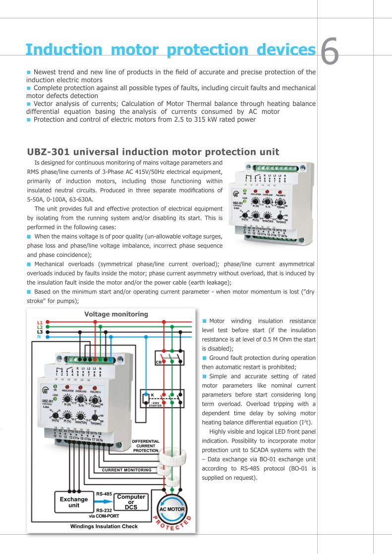
Motor winding insulation resistance
level test before start (if the insulation
resistance is at level of 0.5 М Ohm the start
is disabled);
Ground fault protection during operation
then automatic restart is prohibited;
Simple and accurate setting of rated
motor parameters like nominal current
parameters before start considering long
term overload. Overload tripping with a
dependent time delay by solving motor
heating balance differential equation (I2t).
Highly visible and logical LED front panel
indication. Possibility to incorporate motor
protection unit to SCADA systems with the
– Data exchange via BO-01 exchange unit
according to RS-485 protocol (BO-01 is
supplied on request).
Induction motor protection devicesNewest trend and new line of products in the field of accurate and precise protection of the
induction electric motorsComplete protection against all possible types of faults, including circuit faults and mechanical
motor defects detectionVector analysis of currents; Calculation of Motor Thermal balance through heating balance
differential equation basing the analysis of currents consumed by AC motor Protection and control of electric motors from 2.5 to 315 kW rated power
UBZ-301 universal induction motor protection unitIs designed for continuous monitoring of mains voltage parameters and
RMS phase/line currents of 3-Phase AC 415V/50Hz electrical equipment,
primarily of induction motors, including those functioning within
insulated neutral circuits. Produced in three separate modifications of
5-50А, 0-100А, 63-630А.
The unit provides full and effective protection of electrical equipment
by isolating from the running system and/or disabling its start. This is
performed in the following cases:
When the mains voltage is of poor quality (un-allowable voltage surges,
phase loss and phase/line voltage imbalance, incorrect phase sequence
and phase coincidence);
Mechanical overloads (symmetrical phase/line current overload); phase/line current asymmetrical
overloads induced by faults inside the motor; phase current asymmetry without overload, that is induced by
the insulation fault inside the motor and/or the power cable (earth leakage);
Based on the minimum start and/or operating current parameter - when motor momentum is lost ("dry
stroke" for pumps);
L1L2L3N
voltage monitoring
~240VSTARTER
DIFFERENTIAL CURRENT
PROTECTION
CURRENT MONITORING
AC MOTOR
Computeror
DCS
RS-485
RS-232via COM-PORT
Windings Insulation Check
Exchangeunit
Cb
K

An extended set of integrated protections combining following functions: overload relay, phase monitor relay, over current relay (over current protection with independent and time-dependent delay), leakage current monitor, motor heat protection relay
Monitoring all power parameters and volt-ampere reactiveProtection against long lasting start and rotor jammingPossibility of manual control with use of the device front panelFault history logFree software: Interface panel and SCADA (Novatek Device Manager wizard)
Induction motor protection devicesOperation of UBZ-301 connected to PC or SCADA system allows to control and analyze number of additional parameters:
Data exchange and SCADA integration
UBZ-302 universal electric motor protection deviceDesigned for continuous monitoring of three-phase electrical
equipment parameters (primarily 3-phase asynchronous induction electric motors): mains phase/line voltage, phase/line RMS currents, wattage, positive and negative sequence voltages and currents, insulation resistance to frame, differential ground leakage currents (zero sequence currents), temperature operation modes. The unit has been designed for wide range of applications in the buildings engineering systems (heating, ventilation, water supply, air-conditioning and lifts), Automatic Process Control Systems and Industrial Automation Systems, Control Accounting and Scheduling Systems. The unit allows to reduce the probability of 3-phase electrical equipment failure, reduce the operation cost, optimize the energy consumption and enhance the operational convenience. It is equipped with complete set of protections implemented in UBZ-301. It additionally provides protection against long lasting start and rotor jamming. Besides, the device monitors the motor winding overheating by means of external temperature sensors. Availability of the second output relay allows arranging the following additional operation modes:
Star-delta switching;«Delayed start» power-on (for example, cascade motor connection);Remote signaling system relay
The integrated modem allows for data exchange with relatively positive state systems via RS-232 or RS-485 MOSBUS RTU protocol (selectable).

L1L2L3N
RS-485 INTERFACE TEMPERATURE GND A RS-485 Sensor 1 b RS-485 t R1 100 STANDARD INPUTS Sensor 2 Voltage Current t R1 100
GN
DA
N_U
GN
DA
N_I
MMSP EXCHANGE RS-232 FAULTFunctional relau Power relay UBZ-302 SETUP RES|MEM|SEL TR
TxD_rs232RxD_rs232GND_rs232
27 28 29 30 31 32 33 34 35 39 40 44 45 48 49 50 51 52
R2 R1-1 R1-2
1 2 3 4 5 6 7 8 9 14 15 16 17 18 19 23 24 25 26
CIRCUITbREAKER
M3~
MOTOR ACT1
T2
T3
T4 CONTACTOR
S.No Features
NOvATEKUBZ-302
1 Rated Voltage SupplyPhase voltage
400V – 450V180V – 240V
2 Frequency Operations 45-63Hz
3 External Power Supply Not required (self powered)
4
Required accessoriesPT CT < 63A > 63ACB CT (Earth Leakage)
Not Required (built in)Not required (built in)RequiredProvided
5Output Relay 2
1-Power Relay2-Functional Relay
6 Communication Port- RS-232 RS-485 Modbus RTU
YesYes
7 Operating Temperature -35 to +55°С
8 Measuring Value RMS
9
voltage Protection with Delay Timer1-Under voltage3-Over voltage4-Line Voltage Imbalance5-Wrong Phase Sequence6-Short Circuit7-Phase Loss/ Phase failure8-Single Phasing
YesYesYesYesYesYesYes
10
Current Protection with Delay Timer1-Maximal Current protection 2-Earth Leakage3-Reverse current sequence4-Inverse sequence current5-Minimal current protection6- Current Overload7-Excessive long start
YesYesYesYesYesYesYes
11 Thermal Overload Protection Yes
12Over Heating Protection (external thermal sensors for bearing cage, etc.)
Yes
13 Rotor Jamming Protection Yes
14 Breaker failure Protection Yes
15 Loss of Load Protection Yes
16 Motor Coil Insulation level protection Yes
17 Auto Reclosing/ restarting motor with or without delay
Yes
18 Star Delta Motor Starter Yes
19 Remote tripping of Motor Yes
20
Measurement/ MonitorReal Time Monitoring SoftwareThermal overloadMotor Current Phase & Residual CurrentPhase VoltageLine voltageNegative Sequence Voltage/currentZero sequence voltage/currentFrequencyPower (active, reactive, cos ϕ)Insulation Resistance of MotorExternal temperature measurement
YesYesYesYesYesYesYesYesYesYesYesYes
21 Recording & Analysis of Parameters Yes
22 CB Supervision Yes
23 Fault History log Yes
24 Setting Group Selection Yes
25 Weight 0.56Kg
26 Humidity < 95% non condensing
27Guarantee Guarantee
3-Year Replacement*
Universal AC motor Protection Device – UBZ-302 (SCADA)

Power limiting relay OM-110 is designed for the continuous control over
active and total power capacity of single phase load. Power measurement
range is from 0 - 20 kW or 0 - 20 kVA. Main function of the OM-110 is cutting
off the power load or part of the excessive load basing the user defined
threshold value for maximal power capacity. As soon as the power capacity by
the power load will return to normal operational range after the detected fault
OM-110 will either turn ON the disconnected load with user preset autoreclosing
time or alternatively will block and prevent turning ON the power load back
in this circuit. Thresholds and settings for rated power, tripping time and
autoreclosing time delay are defined by the user by means of DIP switches
and potentiometer knobs on the front panel. Measurement is being performed
with no disconnection of power load my means of current transformer built in to the case of OM-110.
Main applications for the product are – digital wattmeter to measure active or total power, and power
limiting relay to cut off an excessive power load.
Active and reactive power limiters
Single-phase power limiter OM-110
Main functions and basic applications of the Three Phase Power
Limiting Relay OM-310 are as follows:
Total power load cut OFF in case the excessive power consumption
level detected within the user preset time range;
Partial power load cut OFF in case within the user preset
time range the device detects the exceeding of an additional
power threshold setting;
Protection of the equipment and machinery from faults and
consequences of low quality of power supply in electrical circuits;
Measurement and indication of 3 phase power supply parameters: values of acting phase and line voltage;
voltages for positive & negative & neutral sequence; true RMS phase currents; consumed active, reactive
and total load; cos ϕ measurements;
Alarm signalization for the faults;
Remote control over the load – ON/OFF using the interface RS-232/RS485 or alternatively by externally
connected remote switch.
OM-310 provides safe and reliable operation with the power loads from 2.5 kW to 30 kW using it’s
internal built-in current transformers. And in case of connection of standard commercially available current
transformers OM-310 may control and operate with the loads of up to 350 kW including the electrical circuits
with insulated neutral line.
OM-310 provides ultimate protection and control over following faults:
Low quality of power supply voltage (unallowable voltage drops, fluctuations, phase loss, correct phase
sequence control and phase coincidence, imbalance of phase/line voltages);
Over-exceeding of user defined maximal current on any of the phases;
Controls currents of earth leaking to the ground;
Data transmission and operation with the power load, control over main parameters and data exchange
could be realized either through RS-485 MODBUS protocol or using RS-232 interface.
Three-phase power limiter OM-310 (SCADA)

Current control and monitoring relay
RMT-101 Overload relay – Maximal current cut-off relayThe RMT-101 relay is designed to disconnect load with the user preset
time delay when the measured current value exceeds some certain user
defined threshold (independent time delay over current protection). Then with
subsequent autoreclosing time delay it will turn ON the load and start monitoring
the current again. It can also be used for measurement and control over the load
current. Can be used as digital ammeter to monitor actual RMS current. The
measurement process doesn’t interfere the operation of the monitored power
load since it takes place with use of case-integrated current transformer.
RMT-101 allows monitoring the value of current and the load status by means
of digital and LED indicator on the front panel. The RMT-101 relay has two
DIP-switches to select the measurement range: 0-10А with accuracy tolerance
of ± 0А; 0-100А with accuracy tolerance of ± 0.4А and the display mode – actual current/maximum current
indication. The unit keeps the terminals status unchanged if after over current tripping the conductor current
continues to exceed the rated current value. The automatic re-closing/restart relay can be turned off, when
necessary, by switching the tonpot. to ∞ position.
The device can be used as:
Maximal current relay;
Priority load selection relay;
Digital ammeter;
RMT-101 can be used for cutting of part of excessive currents of single phase load in the range from 0 to
24 kVA that is current value of 0 to 100A. This is very useful for various domestic & industrial applications,
especially for load limiting in case of the use of generator back-up or mains.
The rated power values are established in terms of current taking 240 volt as constant. For example,
power of 2 kW will correspond to a current of 8.3A (2000W / 240V).
For ease of calculation please follow the table below: 1 kW = 4.15А
Power, kW Current, А1 4.152 8.33 12.54 16.65 20.8--
10 41.5--
20 8324 100
The device does not require any accessories and has built in CT for sensing load (current). It has one relay
output for switching direct load upto 16A or operating contactor for any load upto 100A (24kW). The digital
display acts as indicator for setting values as well as Ammeter.

Healthy Phase Selector
The PEF-301 universal automatic electronic phase switch (microprocessor-based single phase automatic load transfer device)
The device serves to enhance the power supply reliability for
single-phase consumers, and to protect them from inadmissible voltage
faults and fluctuations. It is designed to supply industrial/ household
single-phase 220-240V/50Hz load from three-phase four-wire mains
3 * 415 + N in order to maintain uninterrupted power supply of essential
single-phase loads and protect them against un-allowable voltage variations
in the mains. Depending on the voltage availability and quality in the main
phase (the priority is set to line 1), the device selects the best healthy
phase and rapidly switches the single-phase load to the phase selected.
When the initial phase voltage parameters are restored, PEF-301 may
switch the load back with the user defined time delay or remain operating
on the line to which it transferred the load. It protects any load up to 3.5 kW – directly by means of the relay
output terminals, over 3.5 kW – via magnetic contactor of appropriate rated power. PEF-301 is widely used
with uninterruptible power systems in such applications as communication and telecommunication, cable TV,
access control systems, countryside and suburban construction, alarm illumination and signalization schemes
and a great variety of other applications.
Scheme Awhen power load is less than 16A
Scheme Bwhen power load is more than 16A - additional contractors should be installed to commutate the corresponding power load
L1L2L3N
K3
L1L2L3N
K2
K1
1 2 3 4 5 6
1 2 3 4 5 6
L1 L2 L3 FAULT
L1 L2 L3 7 8 9 10 11 12
PEF-301Umin(V) Umax(V) Ton(sec) Tr(sec)
100 125 300 50 50 200
175 230 250 300 1 600 5
L1 L2 L3 FAULT
L1 L2 L3 7 8 9 10 11 12
PEF-301Umin(V) Umax(V) Ton(sec) Tr(sec)
100 125 300 50 50 200
175 230 250 300 1 600 5
LOAD AC ~240V
LOAD AC ~240V 16A

Event recorder (Data Logger)
RPM-16-4-3 microprocessor-based USB Flash Drive recorder of electrical and other technological processes parameters
The device is a 16-channel data recorder with possibility to write the information to external media USB-Flash drive. It is manufactured in a plastic casing easily mounted onto a standard DIN-rail in any panel board. The device’s principle of operation is based on collecting readings from all input sensors with subsequent data accumulation in the recorder internal memory (RAM) and saving them to an external media via USB port. RPM-16-4-3 is microprocessor based recorder of electrical process and other parameters/events intended for:
AC voltage RMS value measurement;AC current RMS value measurement;Temperature measurement;Recording data from end devices through standard analog voltage transducer (0-10V) or current output
(4-20mA);Measured values with corresponding time and date marking are stored on an external media (USB-Flash
drive) in form of a simple text file table which could be processed afterwards with any standard PC software.
The device allows to connect and record parameters from up to 16 channels:4 voltage (AC) input channels ranging between 1-500 V directly measured without PT;3 current input channels from 0-1000A through external current transformers, 5A/*** CT;2 channels for temperature measurements from -30 + 79 °С through NТС-type sensors;2 input channels from standard signal transducers with analog output signal (4-20 mА, 0-10V);5 discrete input (digital) channels.
Unlike majority of devices available in the market, the recorder allows not only to present all active information on LCD screen, but also to save it to an external USB Flash Memory of up to 2 Gb capacity with user-specified sampling frequency of 1 – 3600 sec. Saved information can further be presented in form of tables or graphs for analysis with use of free software provided along with device on the USB flash drive.

TR-100 is designed for measurement and control over the temperature of predominantly dry type high voltage transformers by means of four sensors connected to a two- or three-wire diagram, with subsequently displaying the temperature on screen and generating alarms when any parameters come out of the preset range of values.
It can also be used to protect:Motors and generators;Three-phase dry-type transformers with additional
control of cooling of cores and control over the ambient temperature.TR-100 has a flexible power supply and can use any АС/DС voltage from 24 to 260 V, disregarding the polarity. With a little firmware modification the relay functionality can be expanded for monitoring and control other device temperature, including applications within automatic control and management systems, and Automatic Process Control Systems. The unit is equipped with RS-485 MODBUS RTU interface to provide for communication with upper level systems. Free software: interface panel and SCADA Novatek Device Manager wizard.
Multifuntional and programmable temperature controllers (SCADA)
TR-101 is designed for measuring and controlling temperature by means of four sensors connected according to a two- or three-wire diagram, with subsequent temperature display on the front panel. The device has wide application almost in all industrial sectors, in municipal utilities, and agriculture.
The device has the following basic functions and applications:Reading temperature measurements on 4 channels with use
of standard sensors;Controlling temperature according to proportional-integral-
differential (PID) principle;Displaying currently measured temperature value on the integral LED digital display; transferring the measured values for the sensors monitored via RS-485 Modbus RTU standard protocol;detects a break or a short circuit in the connected sensors; Measured temperature digital filtering and correction;Programming using the front panel control buttons or alternatively and via PC connection; settings backup when de-energized;Settings protection from unauthorized change;TR-101 has a flexible power supply and can use any voltage form 24 to 260 V, disregarding polarity.TR-101 can use almost all possibly known standard temperature sensors.
TR-101 Universal and programmable 4 channel temperature relay for monitoring and alarm signalization as well as operation by temperature dependent processes and machinery
TECHNICAL BRIEF
TR-100 Digital temperature relay for the alarm signalization and overheating protection of dry type high voltage transformers
Q-tyof sensors
connectable,pcs
1 – 4
1 – 4
Relay Type
TR-100
TR-101
Supplypower, V
24-255 AC/DC
24-260 AC/DC
Type of temperature measurement
sensors
РТ100, PT1000, KTY83, KTY84, PTC
Pt50, Pt100, Pt500, Pt1000, Cu50, Cu100, Ni100, Ni120, Ni500,
Ni1000, PTC1000
Q-tyof output relays,
pcs
4
4
Measured temperature range, °C
from - 40to +240
from -50 from - 35to +200 to +60
Operation temperature range, °С
from - 35to +60
RS-485 MODBUS
RTU
PID regulation
withkeyword(relay)
Signalization relay outputsK1 - trippingK2 - alarmK3 - ventilationK4 - faultDC
AC~ ~
Cascadeconnection
of PTC sensors (1,3,6 pc.)
22 23 24
22 23 24Connectionof two-wire
sensor
Ground
Channel 1 Channel 2 Channel 3 Channel 4Inputs of temperature sensorsRS-485
Power supply24V DC255V AC
+ -
+ +

MCK-301-8 Control unit for middle and low-temperature refrigerating machines with automatic defrosting
MCK-301-8 is designed to control freezers, refrigerating counters, monobloc units and other refrigerating, retail and industrial equipment that functions according to similar algorithm. The device is an easy substitute for four devices: a three-sensor refrigerator controller with intelligent defrost function, voltage monitor with function of magnetic starter terminals control, electronic module of the compressor heat protection and thermal controller for chamber protection against freezing.
The unit is a highly intelligent programmable device with several access levels. It is intended for controlling both three-phase, and single-phase equipment. Two versions are provided: МСК 301-5 – controller for gas treatment and bananas after ripening chambers, and МСК-301-7 – controller for industrial refrigerating installations with specific operation conditions.
MCK-102-11, MCK-102-20 Control unit for refrigerating machines with an integrated voltage monitor
МСК-102-11, МСК-102-20 is designed to control freezers, refrigerating counters, monobloc units and other refrigerating, retail and industrial equipment. It allows to support specified freezer temperature and perform automatic defrosting. The device performs protective compressor de-energization when un-allowable mains parameters occur (RMS voltage is monitored), and consequent automatic regeneration of voltage parameters after the user-specified time. 24V DC power supply is possible.
To provide for climate control appliances (heaters and air-conditioners) inside satellite communication base stations, two thermal controller versions have been developed on telecommunication base of МСК-301-8: the МСК-301-3 thermal controller (Megafon operator version), and МСК-301-6 (Beeline operator version).
Multifuntional and programmable temperature controllers
TECHNICAL BRIEF
Voltage monitoring
HeatingElement
Alarm
Fan
Compressor
Starter Terminals Monitoring
Door sensor
Chamber sensor
Evaporator 1 sensor
Evaporator 2 sensor
Temperature sensor
Relay Type
MCK-301-8
МСК-102-11
МСК-102-20
Unom,V
240V/415V AC 50Hz
~240V AC 50Hz24V DC
~240V AC 50Hz24V DC
Q-ty of sensors, pcs
4
1
2
Q-tyof output relays, pcs
3
1
2
Type ofsensors
NTC/PTC
NTC
NTC
Monitoring power
supply (U)
+
+
+
Temperature resolution,
°C
0.1
0.1
0.1
Operation temperature range, °С
from - 35to +55
from - 35to +55
from - 35to +55
Dimensions
4 ways
34x77x71(Front panel
IP65 protection,panel board mounting)
34x77x71(Front panel
IP65 protection,panel board mounting)

Transformerless voltage stabilizersLEGAT-15 1.5 kVА
LEGAT-35 3.5 kVА
LEGAT-656.5 kVА
LEGAT-120 12 kVА
Advantages:
Unique transformerless scheme of voltage stabilization and unique unbeatable characteristics (patented)
Input voltage operation mode 90-300 VOutput voltage smooth and stepless regulationLow mass/dimensions parameters
Basic Technical Parameters:
Output voltage regulation accuracy not less than 1.5 %. Feature of output voltage regulation within range of 180-240 V, in 1Volt increments. Start time regulation within range of 3-999 sec. Rate of response to abrupt variation of input voltage less than 0.05 sec. Availability of input and output filters that effectively level the circuit interference. Visual display of input/ output voltage as well as regulator load rate. Protection against current overload, short circuit, overheating, Circuit fault type indication. The regulator allows connecting any types of loads active and reactive.

"Novatek-Electro" LTD.59, Admirala Lazareva StreetOdessa- 65028, UkrainePhone: +38 048 738-00-28Mobile: +38 098 441-92-00Fax: +38 0482 34-36-73E-mail: [email protected]
Global offices
Techmartsupp Solutions Ltd.3B Olaide Benson street,Maryland, Ikeja,Lagos, NigeriaTel: +234 1 8759947, 8971995Cell: +234 (0) 8674-80005E-mail: [email protected] site: www.techmartsupp.com
Global Partners
Lompower Argentina S.A.Belen 315, Lower Floor, Of. ACapital federalArgentina (1407)Tel: +54 (11) 4672-4821Cell: +549 (11) 4993-9996 Web Site: www.lompower.com.ar Contact Person: Ing. Leo Kleiman
INDIAN OFFICE:Novatek India Enterprises Pvt. Ltd.57-A, Pocket-A, Mayur vihar Ph-IIDelhi-110091, IndiaPhone: +91 11 43089550Fax: +91 11 43089581Mobile: +91 9871457676E-mail: [email protected]
RUSSIAN OFFICE:"Novatek-Electro" LTD.Post code 195197; Kondratjievsky avenue 21St-Petersburg, Russian FederationTel:+7 812 740 77 38Fax:+7 812 740 74 55E-mail: [email protected]: technorusMSN: [email protected]

57-A, Pocket-A, Mayur Vihar Ph-IIDelhi – 110091, IndiaTel: +91 11 43089550Fax: +91 11 43089581
Email: [email protected] [email protected]: http://www.novatek-electro.com
NOVATEK INDIA ENTERPRISES PVT. LTD.
Informationprovidedinthiscatalogueissubjecttochangeasperthefuturedevelopmentsmadebythecompanytoenhancethequalityanddurabilityoftheproducts.Novatek-ElectroLtd.retainsallrightsandcopyrightsofthedesignsandproductshighlightedherewith.