isis 3 “qnet” demo - usgs isis: planetary image ... · pdf filethree core windows...
TRANSCRIPT

Isis 3 “qnet” Demo
June 27th, 2012 Tammy Becker / Tracie Sucharski

Create and Edit Control Networks
Objective – Learn about the ISIS control network editor “qnet” – Introduction/Demo of editing functionality
• Creating, modifying, deleting control points • Filtering cubes and control points • Creating ground control points
– Ground source file vs. radius source file

Three core windows Qnet main window similar to qview with most of the same tools

Three core windows Qnet tool window – control point editing

Three core windows Control Network Navigator Window - Filtering
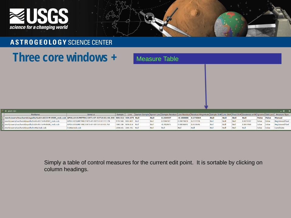
Three core windows + Measure Table
Simply a table of control measures for the current edit point. It is sortable by clicking on column headings.

Three core windows Qnet main window similar to qview with most of the same tools, ie. Zoom, stretch, pan
Cubes displayed through two methods. • Select a Point Id from Control Network Navigator window, then select “View Cube(s)” • Select Cubes from the combo-box at top of Control Network Navigator window, then
double-click on cube filename Control Points drawn on cubes with the following colors: • Green “+” tie point • Magenta “+” ground point • Yellow “+” ignored point • Red “+” point currently being edited (i.e. in Qnet Tool window)
Mouse button functions: • Left: Modify the closest control point • Middle: Delete the closest control point • Right: Create new control point
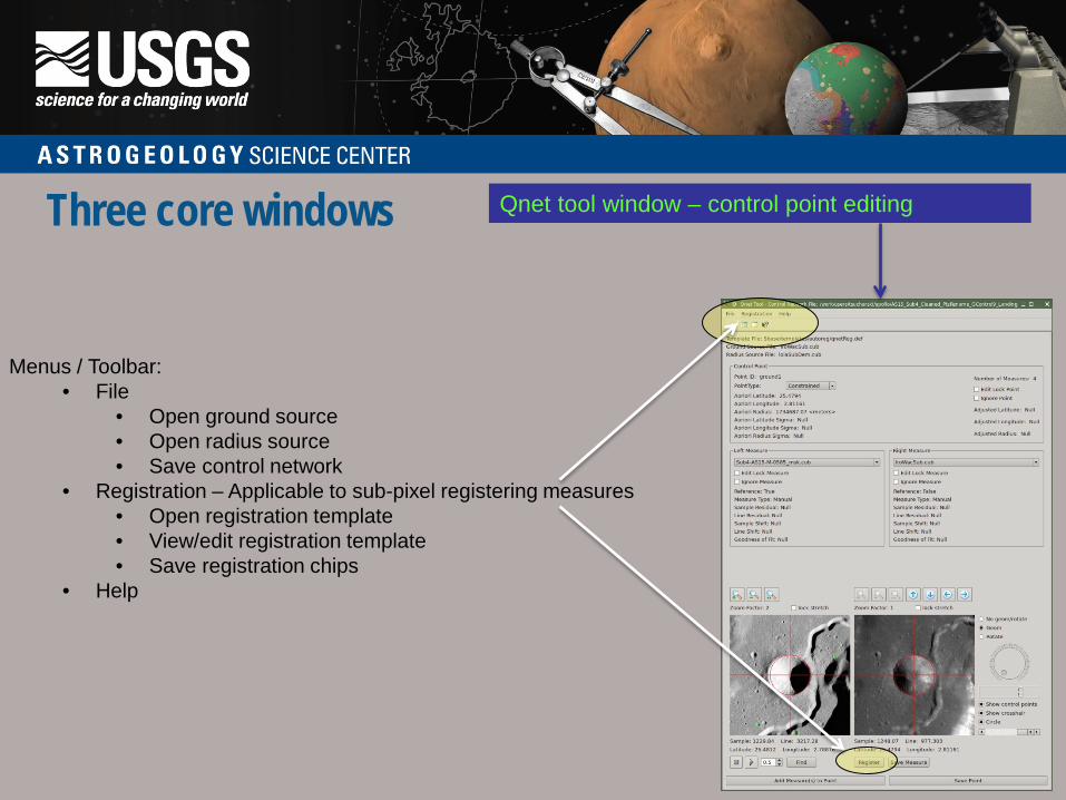
Three core windows Qnet tool window – control point editing
Menus / Toolbar:
• File • Open ground source • Open radius source • Save control network
• Registration – Applicable to sub-pixel registering measures • Open registration template • View/edit registration template • Save registration chips
• Help

Three core windows Qnet tool window – control point editing
Registration Template:
• View and/or edit the registration template The registration template is shown in an editable window. These parameters can be changed and saved for sub-pixel registering the right measure to the left measure.
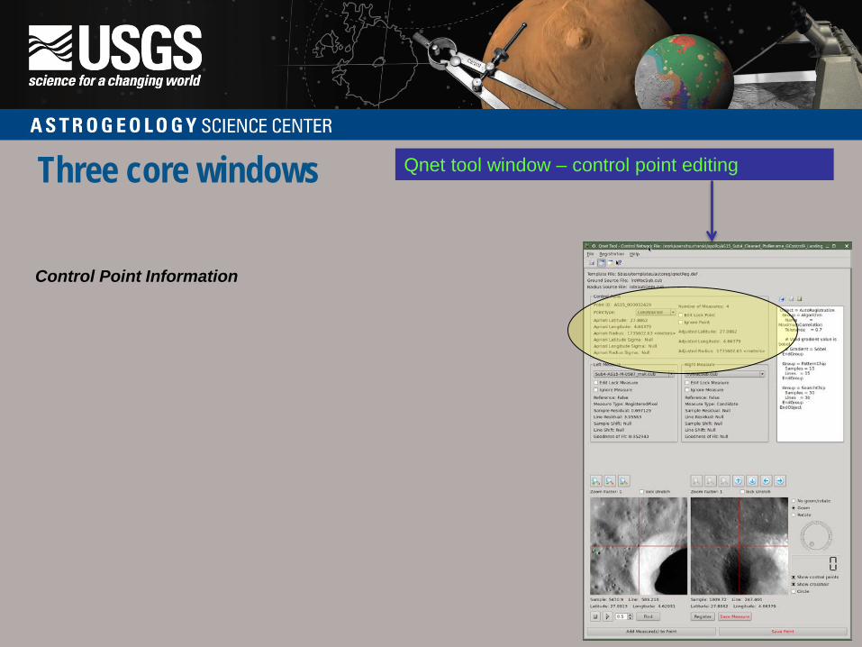
Three core windows Qnet tool window – control point editing
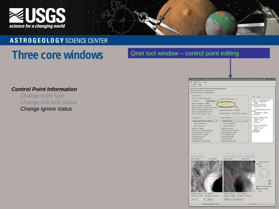
Control Point Information
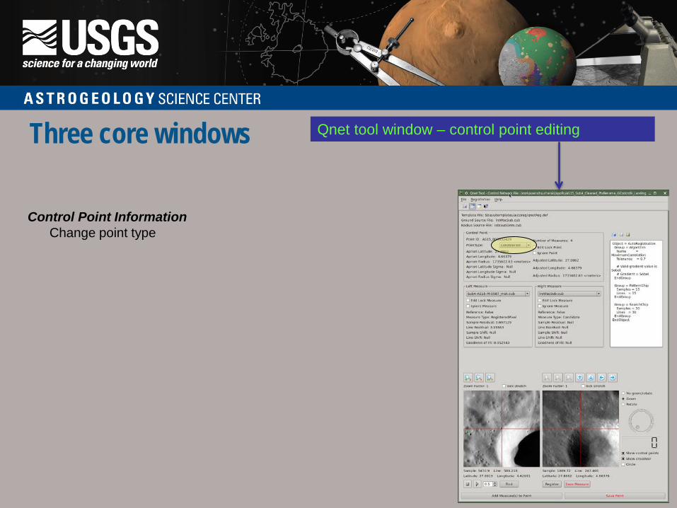
Three core windows Qnet tool window – control point editing
Control Point Information Change point type

Three core windows Qnet tool window – control point editing
Control Point Information Change point type Change edit lock status
Three core windows Qnet tool window – control point editing
Control Point Information Change point type Change edit lock status Change ignore status

Three core windows Qnet tool window – control point editing
Measure Information

Three core windows Qnet tool window – control point editing
Measure Information Change which measures are displayed

Three core windows Qnet tool window – control point editing
Measure Information Change which measures are displayed Change edit lock status

Three core windows Qnet tool window – control point editing
Measure Information Change which measures are displayed Change edit lock status Change ignore status

Three core windows Qnet tool window – control point editing
Zooming Measure Views
The left and right measure views can be zoomed using the zoom buttons above each view. Note: If the Geom button is selected, the right zoom buttons are inactive since the right measure will be scaled to match the left measure.

Three core windows Qnet tool window – control point editing
Changing Measure Locations (right view only) The measure location can be adjusted by: • Move cursor location under the crosshair by clicking left mouse button in the right measure view.

Three core windows Qnet tool window – control point editing
Changing Measure Locations (right view only) The measure location can be adjusted by: • Move cursor location under the crosshair by clicking left mouse button • Move 1 pixel at a time by using arrow keys on the keyboard • Move 1 pixel at a time by using arrow buttons above the right view

Three core windows Qnet tool window – control point editing
Below the left view: • Blink controls: Blink left and right view in left view window using the "Blink Start" button (with play icon) and "Blink Stop" button (with stop icon). Both arrow keys above the right view and the keyboard arrow keys may be used to move the right view while blinking. Note: The left view is the reference measure and cannot be moved.

Three core windows Qnet tool window – control point editing
Below the left view: • Blink controls: Blink left and right view in left view window using the "Blink Start" button (with play icon) and "Blink Stop" button (with stop icon). Both arrow keys above the right view and the keyboard arrow keys may be used to move the right view while blinking. Note: The left view is the reference measure and cannot be moved. • Find: Center right view so that the same latitude / longitude is under crosshair as the left view.

Three core windows Qnet tool window – control point editing
Below the right view: • Register: Sub-pixel register the the right view to the left view.

Three core windows Qnet tool window – control point editing
Below the right view: • Register: Sub-pixel register the the right view to the left view. egisIf sub-pixel registration is successful, statistics are displayed.

Three core windows Qnet tool window – control point editing
Below the right view: • Register: Sub-pixel register the the right view to the left view. If sub-pixel registration is successful, statistics are displayed. RegYou can then choose to “Save Measure” or “Undo Registration”.

Three core windows Qnet tool window – control point editing
Below the right view: • Save Measure: Save the control measure under the right view to the edit control point.

Three core windows Qnet tool window – control point editing
Along the bottom: • Add Measure(s) to Point: Add control measure(s) to the current control point. A dialog will show all cubes in the network with those that fall at this control point's latitude and longitude highlighted. All cubes chosen will be added as control measures to this control point.

Three core windows Qnet tool window – control point editing
Along the bottom: • Add Measure(s) to Point: Add control measure(s) to the current control point. A dialog will show all cubes in the network with those that fall at this control point's latitude and longitude highlighted. All cubes chosen will be added as control measures to this control point. • Save Point: Save the edit control point to the control network.

Three core windows Qnet tool window – control point editing
Other Point Editor Functions Along the right border of the window: • Geom: Geometrically match right view to the left view

Three core windows Qnet tool window – control point editing
Other Point Editor Functions Along the right border of the window: • Geom: Geometrically match right view to the left view • Rotate: Rotate right view using either the dial or entering degrees

Three core windows Qnet tool window – control point editing
Other Point Editor Functions Along the right border of the window: • Geom: Geometrically match right view to the left view • Rotate: Rotate right view using either the dial or entering degrees • Show control points: Draw crosshairs at all control point locations visible within the view • Show crosshair: Show a red crosshair across the entire view • Circle: Draw circle which may help center measure on a crater

Three core windows Control Network Navigator Window - Filtering
Cubes When this is selected, the user may click any of the following buttons: • "View Cube(s)" to open all selected cubes • "Filter" to list all cubes from the currently displayed list that meet the new filtering criteria selected. **Note** If the currently displayed list is already filtered, the new list will only display cubes that meet the criteria of all filters previously chosen until the user resets the list by selecting “Show All”. • "Show All" to reset the list to all images in the network There are 3 filters for the cubes list which display the following: • Cube Name: cubes whose file name contains the user specified string • Number of Points: cubes containing (at least or no more than) the user specified number of points • Distance: cubes that contain at least one pair of points that are within the user specified distance from each other
Three core windows Control Network Navigator Window - Filtering
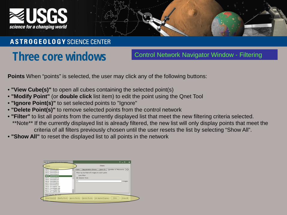
Points When “points” is selected, the user may click any of the following buttons: • "View Cube(s)" to open all cubes containing the selected point(s) • "Modify Point" (or double click list item) to edit the point using the Qnet Tool • "Ignore Point(s)" to set selected points to "Ignore" • "Delete Point(s)" to remove selected points from the control network • "Filter" to list all points from the currently displayed list that meet the new filtering criteria selected. **Note** If the currently displayed list is already filtered, the new list will only display points that meet the criteria of all filters previously chosen until the user resets the list by selecting “Show All”. • "Show All" to reset the displayed list to all points in the network
Three core windows Control Network Navigator Window - Filtering
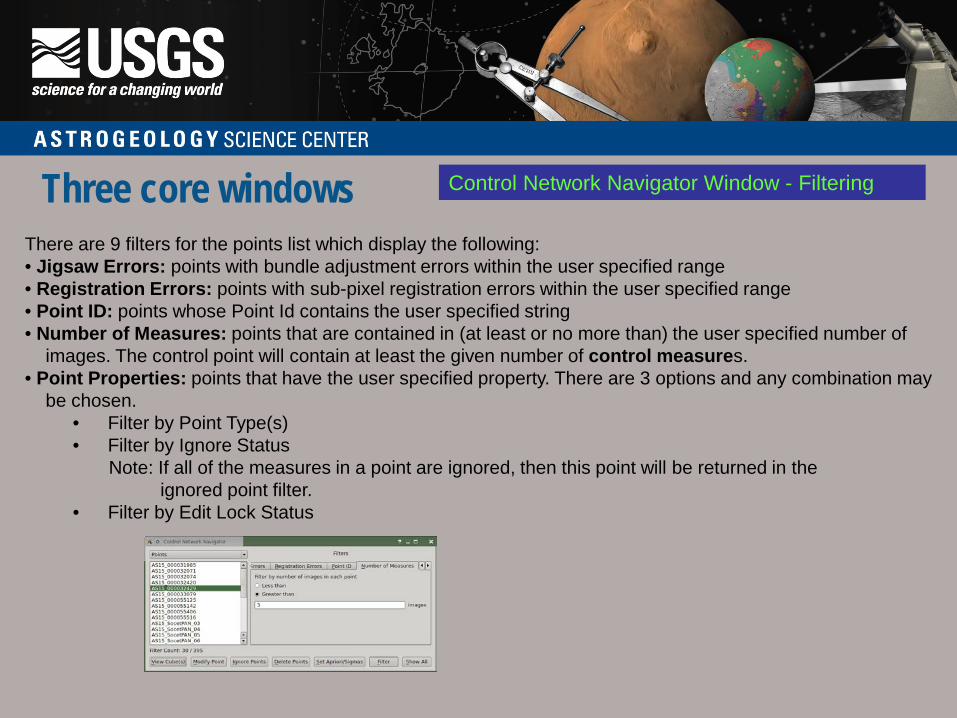
There are 9 filters for the points list which display the following: • Jigsaw Errors: points with bundle adjustment errors within the user specified range • Registration Errors: points with sub-pixel registration errors within the user specified range • Point ID: points whose Point Id contains the user specified string • Number of Measures: points that are contained in (at least or no more than) the user specified number of images. The control point will contain at least the given number of control measures. • Point Properties: points that have the user specified property. There are 3 options and any combination may be chosen.
• Filter by Point Type(s) • Filter by Ignore Status Note: If all of the measures in a point are ignored, then this point will be returned in the ignored point filter. • Filter by Edit Lock Status
Three core windows Control Network Navigator Window - Filtering
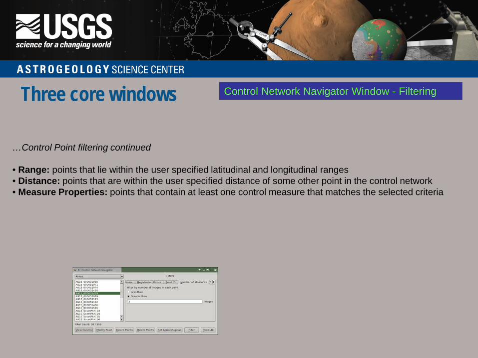
…Control Point filtering continued • Range: points that lie within the user specified latitudinal and longitudinal ranges • Distance: points that are within the user specified distance of some other point in the control network • Measure Properties: points that contain at least one control measure that matches the selected criteria

Tying to Ground
Two ways to open a ground source and a radius source: • File menu of the Qnet main window

Tying to Ground
Two ways to open a ground source and a radius source: • File menu of the Qnet main window • File menu of the Qnet tool window

Tying to Ground Reason for Ground Source vs Radius Source • Easier to visually select points on a basemap or shaded relief of dem than a dem. • Want to use a dem that is not in the Isis data area.
Where does the radius come from if you do not enter a radius source? From the reference measure. If the reference measure was spiceinit ‘ed with a shape model, the radius will come from the shape model, otherwise it will default to the ellipsoid.

Tying to Ground
Methods for creating new ground point: • Right click on ground source viewport • Change current edit point to Fixed or Constrained

Tying to Ground
Methods for creating new ground point: • Right click on ground source viewport click on • Change current edit point to Fixed or Constrained - ground source loaded in right view

Three core windows Control Network Navigator Window – Set Apriori Sigmas
1. Filter points using “Point Properties” tab, selecting “Constrained” and “Fixed”

Three core windows Control Network Navigator Window – Set Apriori Sigmas
1. Filter points using “Point Properties” tab
2. Select points you want to set sigmas on

Three core windows Control Network Navigator Window – Set Apriori Sigmas
1. Filter points using “Point Properties” tab
2. Select points you want to set sigmas on 3. Select “Set Apriori/Sigmas”

Three core windows Control Network Navigator Window – Set Apriori Sigmas
1. Filter points using “Point Properties” tab
2. Select points you want to set sigmas on 3. Select “Set Apriori/Sigmas” 4. Enter Latitude, Longitude and Radius sigmas