is/iec 60947-4-2 (1999): low-voltage switchgear and ...iec 60664 (ali parts), insulation...
TRANSCRIPT

Disclosure to Promote the Right To Information
Whereas the Parliament of India has set out to provide a practical regime of right to information for citizens to secure access to information under the control of public authorities, in order to promote transparency and accountability in the working of every public authority, and whereas the attached publication of the Bureau of Indian Standards is of particular interest to the public, particularly disadvantaged communities and those engaged in the pursuit of education and knowledge, the attached public safety standard is made available to promote the timely dissemination of this information in an accurate manner to the public.
इंटरनेट मानक
“!ान $ एक न' भारत का +नम-ण”Satyanarayan Gangaram Pitroda
“Invent a New India Using Knowledge”
“प0रा1 को छोड न' 5 तरफ”Jawaharlal Nehru
“Step Out From the Old to the New”
“जान1 का अ+धकार, जी1 का अ+धकार”Mazdoor Kisan Shakti Sangathan
“The Right to Information, The Right to Live”
“!ान एक ऐसा खजाना > जो कभी च0राया नहB जा सकता है”Bhartṛhari—Nītiśatakam
“Knowledge is such a treasure which cannot be stolen”
“Invent a New India Using Knowledge”
है”ह”ह
IS/IEC 60947-4-2 (1999): Low-Voltage Switchgear andControlgear : Part 4 - Contractors and Motor-Starters,Section 2: ac Semiconductor Motor Controllers and Starters[ETD 7: Low Voltage Switchgear and Controlgear]


lS/lEC 60947-4-2:1999
W’I’ERT%’=iw
Indian Standard
LOW-VOLTAGE SWITCHGEAR AND CONTROLGEAR
PART 4 CONTRACTORSAND MOTOR-STARTERS
Section 2 ac Semiconductor Motor Controllers and Starters
ICS 29.130.20
October 2007
@ BIS 2007
BUREAU OF INDIAN STANDARDSMANAK BHAVAN, 9 BAHADUR SHAH ZAFAR MARG
NEW DELHI 110002
Price Group 16
lS/lEC 60947-4-2:1999
Low-Voltage Switchgear and Controlgear Sectional Committee, ETD 07
NATIONAL FOREWORD
This Indian Standard (Part 4/See 2) which is identical with IEC 60947+2 : 1999 ‘Low-voltageswitchgear and controlgear — Part 4-2: Contractors and motor-starters — AC semiconductor motorcontrollers and starters’ issued by the International Electrotechnical Commission (l EC) was adoptedby the Bureau of Indian Standards on the recommendation of the Low-Voltage Switchgear andControlgear Sectional Committee and approval of the Electrotechnical Division Council.
The text of IEC Standard has been approved as suitable for publication as an Indian Standard withoutdeviations. Certain conventions are, however, not identical to those used in Indian Standards.Attention is particularly drawn to the following:
a)
b)
Wherever the words ‘International Standard’ appear referring to this standard, they shouldbe read as ‘Indian Standard’.
Comma (,) has been used as a decimal marker, while in Indian Standards, the currentpractice is to use a point (.) as the decimal marker.
In this adopted standard, reference appears to certain International Standards for which IndianStandards also exist. The corresponding Indian Standards, which are to be substituted in theirrespective places, are listed below along with their degree of equivalence for the editions indicated:
International Standard
IEC 60034-1 : 1996 Rotating electricalmachines — Part 1: Rating andperformance
IEC 60050 (161) : 1990 InternationalElectrotechnical Vocabulary (IEV) —Chapter 161: Electromagneticcompatibility
IEC 60269-1 : 1998 Low-voltage fuses— Part 1: General requirements
IEC 60410 : 1973 Sampling plans andprocedures for inspection by attributes
IEC 60439-1 : 1999 Low-voltageswitchgear and controlgear assemblies— Part 1: Type-tested and partially type-tested assemblies
IEC 60664-1 : 19921) Insulationcoordination for equipment within low-voltage systems — Part 1: Principles,requirements and tests
Corresponding Indian Standard
IS 4722 : 2001 Rotating electricalmachines (second revision)
IS 1885 (Part 85) :2003 Electrotechnicalvocabulary: Part 85 Electromagneticcompatibility
IS 13703 (Part 1) : 1993 Low-voltagefuses for voltages not exceeding 1000 Vac or 1500 V dc: Part 1 Generalrequirements
IS 10673 : 1983 Sampling plans andprocedures for inspection by attributesfor electronic items
IS 8623 (Part 1) : 1993 Low-voltageswitchgear and controlgear assemblies:Part 1 Requirements for type-tested andpartially ,type-tested assemblies (first
revision)
IS 15382 (Part 1) : 2003 Insulationcoordination for equipment within low-voltage systems: Part 1 Principles,requirements and tests
Degree ofEquivalence
TechnicallyEquivalent
do
do
do
do
do
‘) Since revised in 2002.
i

WIFC 60947-4-2:1999
International Standard
IEC 60947-1 : 1999’) Low-voltageswitchgezw and controlgear — Part 1:General rules
IEC 64000-3-2 : 1995 Electromagneticcornpatihdity (EMC) — Part 3: Limits —Section 2: Limits for harmonic currentemissions (equipment, inpl,ft:c~~ent .S16 Aper phase)
IEC 61000-4-2 : 1995 Electromagneticcompatibility (EMC) — Part 4: Testingand measurement techniques — Section2: Electrostatic discharge immunity test
EC 61000-4-4 : 1995 Electromagneticcompatibility (EMC) — Part 4: Testingand measurement techniques — Section4: Electrical fast transient/burst immunitytest
CISPR 11:1997 Industrial, scientific andmedical (ISM) radio-frequencyeql!ipment — Eiectro-magneticdisturbance characteristics — Limits andmethods of measurement
Corresponding Indian Standard
lS/lEC 60947-1 : 2004 Low-voltageswitchgear and mntrolgear Part 1General rules
IS 14700 (Part 3/See 2) : 1999Electromagnetic compatibility (EMC):Part 3 Limits, Section 2 Limits forharmonic current emissions (equipmentinput currents 16A per phase)
IS 14700 (Part 4/See 2) : 1999Electromagnetic compatibility (EMC):Part 4 Testing and measurementtechniques, Section 2 Electrostaticdischarge immunity test
1S 14700 “(Part 4/See 4) : 1999Electromagnetic compatibility (EMC):Part 4 Testing and measurementtechniques, Section 4 Electrical fasttransientlburst immunity test
IS 6873 (Part 4) : 1999 Limits andmethods of measurement of radiodisturbance characteristics: Part 4Industrial, scientific and medical (ISM)radio-frequency equipment (first revision)
Degree ofEquivali?nce
Identical
do
do
do
do
The technical committee responsible for the preparation of this standard has reviewed the provisionsof the following International Standard referred in this adopted standard and has decided that they areacceptable for use in conjunction with this standard:
hternatirmal Standard
IIX 60085:1984
IEC 61000-2-1:1990
IEC (’:1090-4-5 :1995
IEC ‘, [~MJ-4-6 :1996
IEC 61000-4-11:1994
Title
Thermal evaluation and classification of electrical insulation
Electromagnetic compatibility (EMC) — Part 2: Environment — Section 1:Description of the environment — Electromagnetic environment for low-frequency conducted disturbances and signaling in public power supplysystems
Electromagnetic compatibility (EMC) — Part 4: Testing and measurementtechniques -- Section 3: Radiated, radio-frequency, electromagnetic fieldimmunity test
Electromagnetic compa@ility (EMC) — Part 4: Testing and measurementtechniques — Section 5: Surge immunity test
Electromagnetic compatibility (EMC) — Part 4: Testing and measurementtechniques — Section 6: Immunity to conducted disturbances, induced byradio-frequency fields
Electromagnetic compatibility (EMC) — Part 4: Testing and measurementtechniques — Section 11: Voltage dips, short interruptions and voltagevariations immunity tests
— -.,..,,....—.—‘; Sirw revised in 2004.
ii
\

ISIIEC 60947-4-2: ~9%?International Standard Title
CISPR 14-1:1993 Electromagnetic compatibility — Requirements for household appliances,electric tools and similar apparatus — Part 1: Emission — Product familystandard
CISPR 14-2:1993 Electromagnetic compatibility — Requirements for “household appliances,electric tools and similar apparatus — Part 2: Immunity — Product ‘fwni!ystandard
Only the English text of the International Standard has been retained while adopting it as an IndianStandard, and as such the page numbers given here are not the same as in the IEC Publication.
For the purpose of deciding whether a particular requirement of this standard is complied with, thefinal value, observed or calculated, expressing the result of a test or analysis, shall be rounded off inaccordance with IS 2 : 1960 ‘Rules for rounding off numerical values (revised’. The number ofsignificant places retained in the rounded off value should be same as that of the specified value inthis standard.
.Ill

lS/lEC 60947-4-2:1999
Indian Standard
LOW-VOLTAGE SWITCHGEAR AND CONTROLGEARPART 4 CONTRACTORSAND MOTOR-STARTERS
Section 2 ac Semiconductor Motor Controllers and Starters
1 Scope and object
This standard applies to controllers and starters, which may include a saries mechanicalswitching device, intended to be connected to circuits, the rated voltaga of which does notexceed 1 000 V a.c.
This standard characterizes controllers and startars with and without bypass maans. I
Controllers and starters dealt with in this standard are not normally designed to interruptshort-circuit currents. Therefore, suitable short-circuit protection (see 8.2.5) should form partof the installation, but not necessarily of the controller or starter.
In this context, this standard gives requirements for controllers and starters associated withseparate short-circuit protective devices.
This standard does not apply to:
continuous operation of a.c. motors at motor speeds other than the normal speed;
semiconductor equipment, including semiconductor contactora (see 2.2.13 of IEC 60947-1)controlling non-motor loads;
electronic a.c. power controllers covered by IEC 60146.
Contractors and control circuit devices used in controllers and starter$ should comply with tharequirements of their relevant product standard. Where mechanical switching devices araused, they should meet the requirements of their own IEC product standard, and theadditional requirements of this standard.
The object of this standard is to state as follows:
the characteristics of controllers and starters and asaodated equipment;
the conditions with which controllers and starters shall comply with reference to:
a) their operation and behaviour;
b) their dielectric properties;
c) the degrees of protection provided by their enclosures where applicable;
d) their construction;
the tests intended for confirming that these conditions have bean met, and the methods tobe adopted for these tests;
the information to be given with the equipment, or in the manufacturer’a literature.
,. 50947-+2 :1999
: f.jii~wlng normative documents contain provisions which, through reference in this text,..,)>?t{lte. provisions of this part of IEC 60947. For dated references, subsequent
I ~,;endrnents to, or revisions of, any of these publications do not apply. However, parties toJg;eements based on this part of IEC 60947 are encouraged to investigate the possibility ofapplying the most recent editions of the normative documents indicated below. For undatedwferences, the latest edition of the normative document referred to applies. Members of IEC:ind 1.S0 maintain registers of currently valid International Standards.
IkG 60034-1:1996, Rotating electrical machines - Part 1: Rating and performance 1)
IEC 60050( 161): 1990, International E/ectrotechnical Vocabulary (IEV) – Chapter 161. Electro-~n:~grretic; compatibility
)‘i C 60085:1984, Thermal evaluation and classification of electrical insulation
i!;C 60269-1:1998, Low-voltage fuses - Part 1: General requirements
[EC 60410:1973, Sampling plans and procedures for inspection by attributes
iEC 60439-1:1992, Low-voltage switchgear and controlgear assemblies - Part 1: Type-tested;,md partial/y type-tested assemblies
iEC 60664 (al I parts), Insulation coordination for equipment within low-voltage systems
i EC 60947-1:1999, Low-voltage switchgear and controlgear - Part 1: General rules
)tmendment 1 (2000) I
i ZCflR3 61000-2-1:1990, Electromagnetic compatibility (EMC) - Part 2: Environment -Section 1.: Description of the environment - Electromagnetic environment for low-frequencyconducted disturbances and signaling in public power supply systems
i ~C 61000-3-2:1995, Electromagnetic compatibility (EMC) - Part 3: Limits - Section 2: Limitsfar harmonic current emissions (equipment input current H 6 A per phase) z)
;K.C 6”! 000-4-2:.1995, Electromagnetic compatibility (EMC) - Part 4: Tasting and measurementft~choiqf~es - Section 2: Electrostatic discharge immunity test - Basic EMC publications)
1, C 61000-4-3:1995, Electromagnetic compatibility (EMC) - Part 4: Testing and measurementi?ch@U6s - Section 3: Radiatad, radio-frequency, electromagnetic field immunity test 4)
......--—--f ) ~here exists a consolidated edition fo.2 (1999) that includes IEC 60034-1 (1996), its amendment 1 (1997) and
amendment 2 (1999).
~; There exists a consolidated edition 1.2 (1996) that includes IEC 61000-3-2 (1995), its amendment 1 (1997) andamendment 2 (1996).
~) ~hele exists a consolidated edition 1.1 (1999) that includes IEC 61000-4-2 (1995) and its amendment 1 (1996).
‘, There exists a consolidated edition 1.1 (1998) that includes IEC 61000-4-3 (1695) and its amandment 1 (1998).
2

ls/lEc 609474-2:1999
IEC 61000-4-4:1995, Electromagnetic compatibility (EMC) - Part 4: Testing and measurementtechniques - Section 4: Electrical fast transient/burst immunity test – Basic EMC publication
IEC 61000-4-5:1995, Electromagnetic compatibility (EMC) – Part 4: Testing and measure ii;anttechniques – Section 5: Surge immunity tast
IEC 61000-4-6:1996, Electromagnetic compatibility (EMC) - Part 4: Testing and maasure[,?enftechniques – Section 6: Immunity to conducted disturbances, induced by radio-frequencyfields
IEC 61000-4-11:1994, Electromagnetic compatibility (EMC) – Part 4: Testing and measuringtechniques - Section 11: Voltage dips, short interruptions and voltage variations immunitytests
Cl SPR 11:1997, Industrial, scientific and medical (ISM) radio-frequency equipment -E/ectromagneti& disturbance characteristics – Limits and methods of measurements)
CISPR 14-1:1993, Electromagnetic compatibility - Requirements for household apj);~f.iic:~~,
e/ectrica/ tooLs and similar apparatus – Part f: Emission – Product family standard
Cl SPR 14-2:1993, Electromagnetic compatibility - Requirements for household appliances,electrical tools and similar apparatus - Part 2: Immunity - Product family standard
3 Definitions
For the purposes of this standard, relevant definitions of clause 2 of IEC 60947-1 and thefollowing additional definitions apply.
3.1 Definitions concerning a.c. semiconductor motor control devices
3.1.1 AC semiconductor motor controllers and starters (see figure 1)
3.1.1.1a.c. semiconductor motor controllersemiconductor switching device (see 2.2.3 of IEC 60947-1) that provides the starting functionfor an a.c. motor and an OFF-state
NOTE Because dangerous Ievela of leakage currents (see 3.1 .13) can exist in a semiconductor motor controller inthe OFF-state, the load terminals should be considered to be live at all times.
5) Thereexlsts a consolidated edi~on 3.1 (1999) that includes CISPR 11 (1997) and its amendment i (! ~ !,
3

lS/lEC 60947-4-2:1999
3.1.1.1.1semiconductor motor controller (form 1)a.c. semiconductor motor controller, in which the starting function may comprise any startingmethod specified by the manufacturer, and that provides control functions which may includeany combination of manoeuvering, controlled acceleration, running or controlled decelerationof an a.c. motor. A FULL-ON state may also be provided
3.1.1.1.2semiconductor soft-start motor controller (form 2)special form of a.c. semiconductor motor controller, in which the starting function. is limited toa voltage and/or current ramp which may include controlled acceleration, and where theadditional control function is limited to providing FULL-ON
3.1.1.1.3semiconductor direct on line (DOL) motor controller (form 3)special form of a.c. semiconductor motor controller, in which the starting function is limited toa full-v~[tage, Unrarnped $tarting method only, and where the additional control fUtICtiOII k
limited to providing FULL-ON
3.1.1.2semiconductor motor starter (form 1, form 2, form 3)a.c, semiconductor motor controller with suitable overload protection, rated, as a unit

lS/lEC 60947-4-2:1999
Device
Semiconductormotor controller
(forms 1, 2, 3)
w
‘otors’aner *
Semiconductor
(forms 1, 2, 3)
Hybrid motorcontroller
HxA”
where x=l,20r3‘=
‘xB*= *
Hybrid motorcontroller
Parellel mechanicalcontact
Bypassed controllerL Semiconductor controller T
(Forms 1,2, 3)
Parallel mechanicalcontact
,
Bypassed hybrid motorHybrid motor controller
controller L r“----””seti””]-””] !--s-iRi&li-GGi-~mechanical ~........~
T,. controller ,i-.,’----contact : !- . .. ...-. _.-_ -_. --.--d L...,.--..---”-- ””.---. . .
(Forms HxA, HxB) (see 8.2.4.2.3)
Hybrid motorForm HIA or HIB Form H2A or H2B Form H3A or H3B
starterwith motor overlosd with motor overload with motor overload
protection protection protection
● Two separate controls for the controller and the series mechanical switching device.
“* One control only for the series mechanical switching device.
Figure 1- Semiconductor motor control devices “1
5

IWEC 60947-4-2:1999
Table 1- Functional possibilities of semiconductor motor control devices
Device Form 1 Form 2 Form 3
semiconductor - OFF—.
- OFF state Not availablenotor controller - Starting function - Starting function
- Menoeuvering - Controlled acceleration- Controlled acceleration - FULL ON
- Running- FULL ON- Controlled deceleration—
semiconductor DOL Not available Not available - OFF statenotor controller - Starting function
- FULL ON
semiconductor Form 1 controller with motor Form 2 controller with Not availablemotor starter overload protection motor overload protectionSemiconductor DOL Not available Not available Form 3 DOL motor con-notw starter troller with motor overload
protection
Hybrid motor HIA: H2A: H3A:controller l-lxA’ - Open - Open - Openwhere x=l,20r3 - OFF state - OFF state - OFF state
- Starthg function - Starting function - Starting function
- Maneuvering - Controlled acceleration - FULL ON
- Controlled acceleration – FULL ON
- Running- Full ON- Controlled deceleration——
Hybrid motor HIB: H2B: H3B:controller HxB’* . - Open - Open - Openwhere x=l,20r3 - Starthg function - Starting function - Starting function
- Maneuvering - Controlled acceleration - FULL ON
- Controlled acceleration - FULL ON
- Running- FULL ON- Controlled deceleration
Hybrid motor starter Form HIA or HIB with motor Form H2A or H2B with Form H3A or H3B withoverload protection motor overload protection motor overload protection
“ Two separate controls for the controller and the series mechanical switching device.
● “ One control only for the series mechanical switching device,
3.1.2 Hybrid motor controllers and starters (see figure 1)
3.1.2.1hybrid motor controllers or starters, form HxA (where x = 1, 2 or 3]form 1, 2 or 3 semiconductor motor controller or starter in series with-a mechanical switchingdevice, all rated as a unit. Separate control commands are provided for the series mechanicalswitching device and the semiconductor motor controller or starter. All the control functionsappropriate to the form of motor controller or starter specified are provided, together with anOPEN position
6

3.1.2.2hybrid motor controllers or starters, form HxBform 1, 2 or 3 semiconductor motor controller or starter in series
lS/lEC 60947-4-2:1999
with a mechanical switchingdevice, all rated as a unit. A single control command is provided for both the seriesmechanical switching device and the semiconductor motor controller or starter. All the controlfunctions appropriate to the form of motor controller specified are provided, with the exceptionof an OFF state
3.1.2.3OPEN positioncondition of a hybrid semiconductor motor controller or starter when the series mechanicalswitching device is in the OPEN position (see 2.4.21 of IEC 60947-1)
3.1.3current-limit functionability of the controller to limit the motor current to a specified value. It does not includethe ability to limit the instantaneous current under conditions of short circuit
3.1.4manceuvreany deliberate operation that causes current changes which must be characterized andcontrolled (for example jogging, braking)
NOTE 1 Starting is a mandatory manoeuvre that is recognized separately.
NOTE 2 Braking operations performed by the a.c. semiconductor motor controller or starter are considered to bea manoeuvre within the scope of this standard.
3.1.5controlled accelerationcontrol of motor performance while
3.1.6controlled decelerationcontrol of motor performance while
3.1.7controlled runnincr
increasing motor speed by acting on the motor supply
decreasing motor speed by acting on the motor supply
control of motor p&formance by acting on the motor supply while the motor is running atnormal speed (for example energy saving)
3.1.8prospective locked rotor current, (/LRP)prospective current (see 2.5.5 of IEC 60947-1) that would flow when the rated voltage isapplied to the motor with a locked rotor
3.1.9ON-statethe condition of a controller when the conduction current can flow through its main circuit
3.1.10FULL-ON (state of controllers)the condition of a controller when the controlling functions are set to provide normal fullvoltage excitation to the load

ISIIEC 60947-4-2:1999
3.1.11minimum load currentminimum operational current in the main circuit which is necessarv for correct action ofa controller in the ON-state
NOTE The minimum load current should be given as the r.m. s value.
3.1.12OFF-statethe condition of a controller when no control signal is applied,the OFF-state leakage current flows through the main circuit
3.1.13OFF-state leakage current (IL)
and no current exceeding
the current which flows through the main circuit of a controller in the OFF-state
3.f.14operation (of a controller)transition from the ON-state to the OFF-state, or the reverse
3.1,15operating cycle (of a controller)succession of operations from one state to the other and back to the first state
NOTE A succession of operationa not forming an operating cycle is referred to as an operating series.
3.1.16operating capabilityunder prescribed conditions, the ability to perform a series of operating cycles without failure
3.1.17overload current profilecurrent-time co-ordinate specifying the requirement to accommodate overload currents for aperiod of time (see 5.3.5.1)
3.1.16rating indexrating information organized in a prescribed format, unifying rated operational current and thecorresponding utilization category, overload current profile, and the duty cycle or OFF-time(see 6.le))
3.1.19tripping operation (of a controller or starter)operation to establish and maintain an OFF-state (or open position in the case of a form HxBcontroller or starter) initiated by a control signal
3.1.20trip-free controller or startercontroller or starter which establishes and sustains an OFF-state condition, which cannot beoverridden in the presence of a trip condition
NOTE In the caae of form HxB, the term “OFF-state condition” is replaced by the term “OPEN position”.

IS/lEC 60947-4-2:1999
3.1.21phase loss sensitive thermal overload relay or releasea multipole thermal overload relay or release which operates in case of overload and also incase of loss of phase in accordance with specified requirements
3.1.22ON-timeperiod of time during which the controller is on-load, for example as in figure F.1 of annex F
3.1.23OFF-timethe period of time during which the controller is off-load, for example as in figure F.1 ofannex F
3.1.24bypassed controllerequipment wherein the main circuit contacts of a mechanical switching device are connectedin parallel with the main circuit terminals of a semiconductor switching device, and whereinthe operating means of the two switching devices are co-ordinated
3.2 EMC definitions
Various EMC definitions are given in IEC 60050, particularly chapter 161. Further explan-ations are given in IEC 61000-2-1. For convenience and to avoid confusion, some of the keydefinitions from IEC 60050(161) are reproduced here
3.2.1electromagnetic compatibility EMC (abbreviation)ability of an equipment or system to function satisfactorily in its electromagnetic environmentwithout introducing intolerable electromagnetic disturbances to anything in that environment[IEV 161-01-07]
3.2.2electromagnetic emissionphenomenon by which electromagnetic energy emanates from a source [IEV 161-01-08]
3.2.3electromagnetic disturbanceany electromagnetic phenomenon which may degrade the performance of a device,equipment or system, or adversely affect living or inert matter [IEV 161-01-05]
NOTE An electromagnetic disturbance may be an electromagnetic noise, an unwanted signal, or a change In th.propagationmediumitself.
3.2.4radio (frequency) disturbanceelectromagnetic disturbance having components in the radio frequency range [IEV 161-01-13]
9

lS/lEC 60947-4-2:1999
3.2.5radio frequency interference, RF I (abbreviation)degradation of the reception of a wanted signal caused by radio frequency disturbance[IEV 161-01-14]
NOTE The English words “interference” end “disturbance” are often used indiscriminately. The expression radio-frequency interference’ is also commonly applied to a radio-frequency disturbance of an unwanted signal.
3.2.6transient (adjective and noun)pertaining to or designating a phenomenon or a quantity which varies between twoconsecutive steady states during a time interval short compared with the time-scale of interest[IEV 161-02-01]
3.2.7burst (of pulses or oscillations)sequence of a limited number of distinct pulses or an oscillation of limited duration [IEV 161-02-07]
3.2.8voltage surgetransient voltage wave propagating along a line or a circuit and characterized by a rapidincrease followed by a slower decrease of the voltage [IEV 161-08-11]
4 Classification
Subclause 5.2 gives all data which could be used as criteria for classification.
5 Characteristics of a.c. semiconductor motor controllers and starters
5.1 Summary of characteristics
The characteristics of controllers and starters shall be stated in the following terms, wheresuch terms are applicable:
- type of equipment (5.2);
- rated and limiting values for main circuits (5.3);
- utilization category (5.4);
– control circuits (5.5);
- auxiliary circuits (5.6);
- types and characteristics of relays and releases (5.7);
- co-ordination with short-circuit protective devices (5.8);
– switching overvoltages (5.9).
5.2 Type of equipment
The following shall be stated:
5.2.1 Form of equipment
Forms of controllers and starters (see 3.1.1 and 3.1.2).
10

lS/lEC 60947-4-2:1999
5.2.2 Number of poles
5.2.2.1 Number of main poles
5.2.2.2 Number of main poles where the operation is controlledby a semiconductor switching element
5.2.3 Kind of current
AC only.
5.2.4 interrupting medium (air, vacuum, etc.)
Applicable only to mechanical switching devices of hybrid controllers and starters.
5.2.5 Operating conditions of the equipment
5.2.5.1 Method of operation
For example:
symmetrically controlled controller (such as a semiconductor with fully controlled phases);
non-symmetrically controlled controller (such as thyristors and diodes).
5.2.5.2 Method of control
For example: ‘
automatic (by pilot switch or sequence control);
non-automatic (that is push-buttons);
semi-automatic (that is partly automatic, partly non-automatic).
5.2.5.3 Method of connecting
For example (see figure 2):
motor in delta, thyristors in series with a winding;
motor in star, thyristors in delta;
motor in delta, thyristors connected between winding and supply.
5.3 Rated and limiting values for main circuits
The rated and limiting values established for controllers and starters shall be stated inaccordance with 5.3.1 to 5.3.6, but it may not be necessary to establish all applicable valuesby tests.
5.3.1 Rated voltages
A controller or starter is defined by the following rated voltages.
5.3.1.1 Rated operational voltage (Ue)
Subclause 4.3.1.1 of IEC 60947-1 applies.
11

IWEC 60947-4-2:1999
5.3.1.2 Rated insulation voltage (L/i)
Subclause 4.3.1.2 ofl EC 60947-1 applies
5.3.1.3 Rated impulse withstand voltage (Uirnp)
Subclause 4.3.1.3 of IEC 60947-1 applies,
12

lS/lEC 60947-4-2:1999
‘Figure 2a - Motor in delta - Thyristors in series with a winding
1
x
(
Figure 2b - Motor in star - Thyristors in delta
1 2 3
x
x
Figure 2C - Motor in delta - Thyristors connected between winding and supply
Figure 2- Connecting methods
13

IWEC 60947-4-2:1999
5.3.2 Currents
A controller or starter is defined by the following currents:
5.3.2.1 Conventional free air thermal current (/~h)
Subclause 4.3.2.1 of IEC 60947-1 applies.
5.3.2.2 Conventional enclosed thermal current (/th~)
Subclause 4.3.2.2 of IEC 60947-1 applies.
5.3.2.3 Rated operational current (/e)
The rated operational current, /e, of controllers and starters is the normal operating currentwhen the device is in the FULL-ON state, and takes into account the rated operational voltage(see 5.3. 1.1), the rated frequency (see 5,3.3), the rated duty (see 5.3.4), the utilizationcategory (see 5.4), the overload characteristics (see 5,3,5), and the type of protectiveenclosure, if any.
5,3,2.4 Rated uninterrupted current (Iu)
Subclause 4.3.2.4 of IEC 60947-1 applies.
5.3.3 Rated frequency
Subclause 4.3.3 of IEC 60947-1 applies.
5.3.4 Rated duty
The rated duties considered as normal are as follows:
5.3.4.1 8 h duty
A duty in which the controller or starter remains in the FULL-ON state while carrying a steadycurrent long enough for the equipment to reach thermal equilibrium, but not for more than 8 h,without interruption.
5.3.4.2 Uninterrupted duty
A duty in which the controller or starter remains in the FULL-ON state while carrying a steadycurrent without interruption for periods of more than 8 h (weeks, months, or even years).
5.3.4.3 Intermittent periodic duty or intermittent duty
Subclause 4.3.4.3 of IEC 60947-1 applies, except that the first paragraph is changed to read:
“A duty with on-load periods in which the controller or starter remains in the FULL-ON state,having a definite relation to off-load periods, both periods being too short to allow theequipment to reach thermal equilibrium.”
14

lS/lEC 60947-4-2:1999
5!3.4.4 Temporary duty
Duty in which the controller or starter remains in the FULL-ON state for periods of timeinsufficient to allow the equipment to reach thermal equilibrium, the current-carrying periodsbeing separated by off-load periods of sufficient duration to restore equality of temperaturewith the cooling madum. Standard values of temporary duty are:
30 s, 1 rein, 3 rein, 10 rein, 30 rein, 60 min and 90 min
5.3.4.5 Periodic duty
Subclause 4.3.4.5 of IEC 60947-1 applies.
5.3.4.6 Duty cycle values and symbols
For the purpose of this standard, the duty cycle is expressed by two symbols, F and S. Thesedescribe the duty, and alao set the time that must be allowed for cooling.
F ia the ratio of the on-load period to the total period expressed as a percentage
The preferred values of F are:
F = 1 0/6,5 “h, 15 “~, 25 %, 40 ~o, 50 ‘%0, 60 ‘A, 70 ‘h, 80 ~0, 90 ‘h, 99 ~0.
S is the number of operating cycles per hour. The preferred values of S are:
S = 1, 2, 3, 4, 5, 6, 10, 20, 30, 40, 50, 60 operating cycles per hour.
NOTE Other values of F andlor S maybe declared by the manufacturer.
5.3.5 Normal load and overload characteristics
Subclause 4.3.5 of IEC 60947-1 applies, with the following additions.
5.3.5.1 Overload current profile
The overload current profile gives the current-time co-ordinates for the controlled overloadcurrent. It is expressed by two symbols, X and TX.
X denotes the overload current as a multiple of /e selected from the array of values in table 4,and represents the maximum value of operating current due to starting, operating, ormaneuvering under overload conditions. X = /LRP//a when no current limit function isprovided.
Deliberate overcurrents not exceeding 10 cycles (for example boost, kickstart, etc.), whichmay exceed the stated value of X x /e, are disregarded for the overload current profile.
Tx denotea the aum of duration times for the controlled overload currents during starting,operating, and maneuvering. See table 4.
For a starter, TXis the minimum operating time allowed by the tolerances of the overload relayfor the current X x /e in the cold state.
15

I ._.L”~ .. . ,., -.,——.
f *
,
I
I~
II,:
1,‘~
lS/lEC 60947-4-2:1999
5.3.5.2 Operating capability
Operating capability represents the combined capabilities of:
- current commutation and current carrying in the ON-state; and
- establishing and sustaining the OFF-state (blocking),
at full voltage under normal load and overload conditions in accordance with utilizationcategory, overload current profile and specified duty cycles.
Operating capability is characterized by:
- rated operational voltage (see 5.3.1.1 );
- rated operational current (see 5.3.2.3);
- rated duty (see 5.3.4);
- overload current profile (see 5.3.5.1);
- utilizawr, ~ategory (eee 5.4).
Requirement are given in 8.2.4.1
5.3.5.3 Starting, stopping and maneuvering characteristics
Typical service conditions for controllers and starters controlling squirrel cage and hermeticrefrigeration motors are as follows:
5.3.5.3.1 Starting characteristics of squirrel cage and hermetic refrigeration motors
a) One direction of rotation with the inclusion of phase-control capability to provide anycombination of controlled acceleration to normal speed, controlled deceleration to standstill,or an occasional manoeuvre without de-energizing the controller (AC-53a, AC-58a).
b) One direction of rotation with the inclusion of phase-control capability to provide controlledacceleration to normal speed. Controllers and starters are rated for intermittent duty only(AC-53b, AC-58 b); for example after starting, the motor may be connected into ‘a circuitthat bypasses the power semiconductors.
Two directions of rotation may be accomplished by reversing the connections to the controlleror motor by means that are beyond the scope of this standard, but are covered by therelevant product standard for the selected means.
Two directions of rotation may also be accomplished by phase reversing within the controlleror starter. The requirements for this operation will vary with each application. Therefore, thisis subject to agreement between manufacturer and user.
Due to the control capability of controllers and starters, the current during starting, stopping,and any manoeuvre will differ from the conventional values of the prospective locked rotorcurrent listed in table 6.
16

lS/lEC 60947-4-2:1999
5.3.5.3.2 Starting characteristics of rheostatic rotor starters with control Iersenergizing the stator (AC-52a, AC-52b)
Starters can be used to provide reduced voltage excitation to the stator windings of a slip ringmotor, and thereby reduce the number of switching steps required in the rotor circuit. Formost applications, one or two starting steps are adequate depending upon load torque andinertia, and the severity of start required.
NOTE Starters and controllers covered by this standard are not intended for use in the rotor circuit and therefore,the rotor circuit must be controlled by traditional means. The relevant product standards for the rotor circuits ofrheostatic rotor starters should apply.
5.3.6 Rated conditional short-circuit current
Subclause 4.3.6.4 of IEC 60947-1 applies.
5.4 Utilization category
Subclause 4.4 of IEC 60947-1 applies, with the following addition.
For controllers and starters, the utilization categories as given in table 2 are consideredstandard. Any other type of utilization shall be based on agreement between manufacturerand user, but information given in the manufacturer’s catalogue or tender may constitute suchan agreement.
Each utilization category (see table 2) is characterized by the values of the currents, voltages,power-factors and other data of tables 3, 4, 5 and 6, and by the test conditions specified inthis standard.
The first digit of the utilization category identification designates a semiconductor motorcontroller or starter. The second digit designates a typical application. The a-suffix designatesthe capability of a controller to perform any of the functional possibilities listed in table 1. Theb-suffix designates the capability of a controller where it is restricted to performing a transitionfrom an OFF-state to a starting function of duration Tx, and immediately returning to the OFF-state to comprise a duty cycle in accordance with the requirements of 8.2.4.1.
5.4.1 Assignment of ratings based on the results of tests
A designated controller or starter with a rating for one utilization category which has beenverified by testing can be assigned other ratings without testing, provided that:
the rated operational current and voltage that are verified by testing shall not be Ieaa thanthe ratings that are to be asaigned without testing;
the utilization category and duty cycle req~rements for the tested rating shall be equal toor more severe than the rating that is to be assigned without testing; the relative Ievela ofseverity are given in table 3;
the overload current profile for the tested rating shall be equal to or more severe than therating that is to be aasigned without testing, in accordance with the. relative levels ofseverity in table 3. Only values of X lower than the tested value of X may be assignedwithout testing.
17

lS/lEC 60947-4-2:1999
Table 2- Utilization categories
I_Utilizationcategory
Typical application
I AC-52a Control of slip ring motor stators: 8 h duty with on-load currents for start, acceleration, runr
AC-52b Control of slip ring motor stators: intermittent duty
AC-53a Control of squirrel caga motors: 8 h duty with on-load currants for start, acceleration, run
\ AC-53b \Control ofsquirrel cage motors: intermittent duty I
iAC-58a Control of hermetic refrigerant compressor motors with automatic resetting of overload releases:
8 h duty with on-load currents for start, acceleration, run I
AC-58b Control of hermetic refrigerant compressor motors with automatic resetting of overload releases:intermittent duty
NOTE 1 The means of bypassing the semiconductor controller may be integral with the controller/starter orinstalled separately.
NOTE2 Ahermetic refrigerant compressor motor isacombination consisting ofacompressor andmotor, bothof which are enclosed in the same housing, with no external shaft or shaft seals, the motor operating in therefrigerant.
Table 3- Relative levels of severity
SeverityOverload current profile
level Utilization categoryTime related
(X-TX) requirement
AC-52aHighest value of
AC-53aHighest value of
AC-58a(Xle)z x TX(note 1) F x S (note 2)
Most severeAC-52b
Highest value ofAC-53b
Lowest value of
AC-58b(Xle)z x TX(nota 1) OFF-tim6 (note 3)
,
I NOTE1 When thehighaet value of (Xle)2x Txoccurs atmorathan one value of Xle, then the highestvalue of X/e shall apply. I
I NOTE2 When thahighest value of FxSoccurs atmorethan onevalue of S,thenthe highest value ofS shall apply. I
I NOTE3 When the highest value of (X/e)2x TX occurs at more than one value of OFF-time, then theIowast value of OFF-time shall apply. I
5.5 Control circuits
Subclause 4.5.1 of IEC 60947-1 applies, with the following additions:
Refer to annex G for examples and illustrations. The characteristic of electronic controlcircuits are:
- kind of current;
- power consumption;
- rated frequency (or d.c.);
- rated control circuit voltage, UC(nature: a.c./d.c.);
- rated control supply voltage, Ua (nature: a.c./d. c.);
~ nature of control circuit devices (contacts, sensors).
NOTE A distinction is made betwean control circuit voltage, L/c, which ia the controlling input signal, and controlsupply voltage, Us, which is the voltage applied to energize the power supply terminals of the control circuitequipment and may be diffarant from L/c, due to built-in transformers, rectifiers, resistors, etc.
18

“ lS/lEC 60947-4-2:1999
5.6 Auxiliary circuits
Subclause 4.6 of IEC 60947-1 applies, with the following additions:
Electronic auxiliary circuits perform useful functions (for example monitoring, data acquisition,etc. ) that are not necessarily relevant to the direct task of governing the intended performancecharacteristics.
Under normal conditions, auxiliary circuits are characterized in the same way as controlcircuits, and are subject to the same kinds of requirements. If the auxiliary functions includeunusual performance features, the manufacturer should be consulted to define the criticalcharacteristics.
5.7 Characteristics of relays and releases (overload relays)
Clause B.1 applies to relays and releases provided for motor protection.
5.8 Co-ordination with short-circuit protective devices (SCPD)
Controllers and starters are characterized by the type, ratinga, and characteristics of theSCPD to be used to provide overcurrent discrimination between starter and SCPD, andadequate protection of controllers and startere against short-circuit currents.
Requirements are given in 8.2.5 of this standard and in 4.8 of IEC 60947-1.
5.9 Switching overvoltages
Under consideration.
6 Product information
6.1 Nature of information
The following information shall
/dentificafion
be given by the manufacturer:
a) the manufacturer’s name or trademark;
b) type designation or serial number;
c) number of this standard.
Characteristics, basic rated values and utilization
d) rated operational voltages (see 5.3,1.1);
e) rated operational currents, corresponding utilization category (5.4), overload currentprofile (5.3.5.1), and duty cycle (5.3.5.2) or OFF-time, comprising the rating index.
The prescribed format for AC-52a, AC-53a, AC-58a is shown by these examples:
fOO A: AC-53a: 6-6: 60-1
This indicates 100 A current rating for general applications with squirrel cage motors. Thedevice can accommodate 600 A for 6 s; 60 “A on-load factor; one standard operating cyclepar hour.
19
lS/lEC 60947-4-2:1999
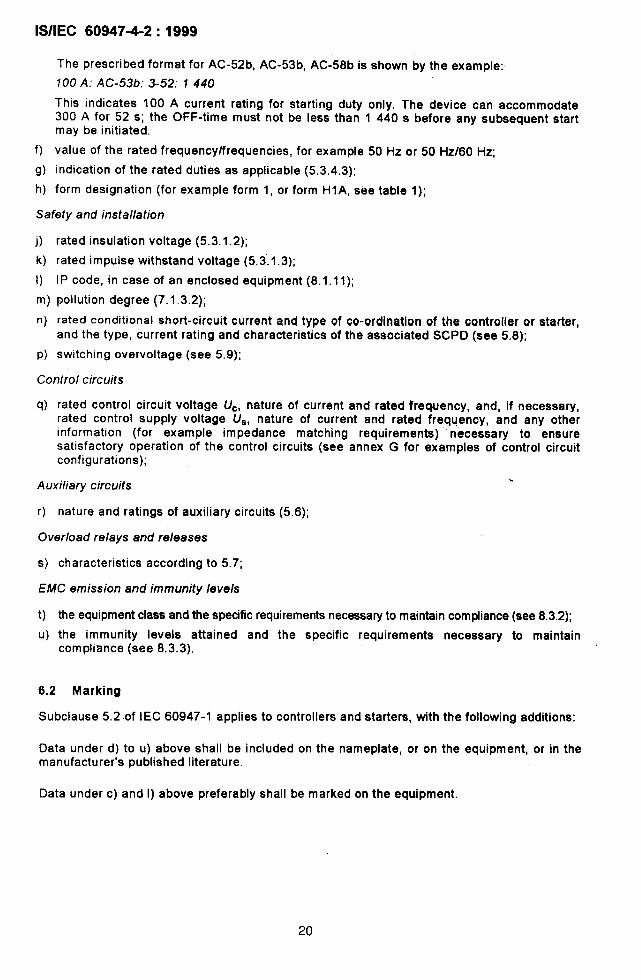
The prescribed format for AC-52b, AC-53b, AC-58b is shown by the example:
fOO A: AC-53b: 3-52:1440
This indicates 100 A current rating for starting duty only. The device can accommodate300 A for 52 s; the OFF-time must not be less than 1 440 s before any subsequent startmay be initiated.
f)
9)
h)
value of the rated frequency/frequencies, for example 50 Hz or 50 Hz/60 Hz;
indication of the rated duties as applicable (5.3.4.3):
form designation (for example form 1, or form HI A, see table 1);
Safety and insta//ation
O
k)
1)
m)
n)
P)
rated insulation voltage (5.3.1.2);
rated impulse withstand voltage (5.3”.1.3);
1Pcode, in case of an enclosed equipment (8.1.11);
pollution degree (7.1,3.2);
rated conditional short-circuit current and type of co-ordination of the controller or starter,and the type, current rating and characteristics of the aaaociated SCPD (ace 5.8);
switching overvoltage (see 5.9);
Contro/ circuits
q) rated control circuit voltage UC, nature of current and rated frequency, and, if necessary,rated control supply voltage Us, nature of current and rated frequency, and any otherinformation (for example impedance matching requirementa) ‘necessary to ensuresatisfactory operation of the control circuits (see annex G for examples of control circuitconfigurations);
Auxiliary circuits%
r) nature and ratings of auxiliary circuits (5.6);
Overload relays and releases
s) characteristics according to 5.7;
EMC emission and immunity levels
t) the equipment class and the specific requirements necessary to maintain compliance (see 8.3.2);
u) the immunity levels attained and the specific requirements necessary to maintaincompliance (see 8.3.3).
6.2 Marking
Subclause 5.2 .of IEC 60947-1 applies to controllers and starters, with the following additions:
Data under d) to u) above shall be included on the nameplate, or on the equipment, or in themanufacturer’s published literature.
Data under c) and 1) above preferably shall be marked on the equipment.
20
lS/lEC 6064742:1999
6.3 Instructions for installation, operation, and maintenance
Subclauae 5.3 of IEC 60947-1 appliea, with the following addition:
Information shall be provided by the manufacturer to advise the ueer on the measures to betaken with regard to the equipment:
in the event of a short circuit;
- in connection with the requirements for EMC (see 8.3.2).
7 Normal service, mounting and transport conditions
Clause 6 of IEC 60947-1 applies, with the following exceptions:
7.1 Normal service conditions
Subclause 6.1 of IEC 60947=1 applies, with the following exceptions:
7.1.1 Ambient air temperature
The ambient air temperature does not exceed +40 “C, and its average over a period of 24 hdoes not exceed +35 “C.
The lower limit of the ambient air temperature is O“C.
Ambient air temperature is that existing in the vicinity of the equipment if supplied withoutenclosure, or in the vicinity of the enclosure if supplied with an enclosure.
NOTE If the equipment Is to be used at ambient air tamperaturea above +40 “C (for examplowithin swltohgearand control gear assemblies and in forges, tiller rooms, tropioal oountrias) or below O “C (for ●xamplo -25 ●C, aarequired by IEC S0439-1 for outdoor inetalled low-voltage switchgear and controlgear aaeemblies) the manufacturershould be consulted. Information given in the manufacturers cstalogue may satisfy this requirement.
7.1.2 Altitude
The altitude of the site of installation doea not exceed 1000 meters.
NOTE For equipment to be used at higher altitudes, it is necaaaary to take into account the reduction of thedielectric strength, and the cooling effect of the air. Electrical equipmant intended to operate in ‘these condtiionashall be desiened or used in accordance with an agreement between manufacturer ●nd user.
7.1.3 Atmospheric conditions
7.1.3.1 Humidity
Subclauae 6.1.3.1 of IEC 60947-1 applies.
7.1.3.2 Degrees of pollution
Unless otherwise stated by the manufacturer, controllers and starters are intended for uae inpollution degree 3 environmental conditions, as defined in 6.1.3.2 of IEC 60947-1. However,other pollution degreea may be considered to apply, depending upon the micro-environment.
21

lS/lEC 60947-4-2:1999
7.4.4 Shock and vibrations
Subclause 6.1.4 of IEC 60947-1 applies
7.2 Conditions during transport and storage
Subclause 6.2 of iEC 60947-1 applies.
7.3 Mounting
Subclause 6.3 of IEC 60947-1 applies, and for EMC considerations, see 8.3 and 9.3.5 below.
7.4 Electrical system disturbances and influences
For EMC considerations, see 8.3 and 9.3.5.
8 Constructional and performance requirements
801 Constructional requirements
NOTE Further requirements concerning meteriels and current-cerrying parts ere under consideration for 7.1.1 and7.1.2 of IEC 60S47-1. Their application to this standard will be subject to further consideration.
8.1.1 Materials
Subclause 7.1.1 of IEC 60947-1 applies (see note to 8.1).
8.1.2 Current-carrying parts and connections
Subclause 7.1.2 of IEC 60947-1 applies (see note to 8.1).
8.1.3 Clearances and creepage distances
Subclause 7.1.3 of IEC 60947-1 applies with the following additional requirement. Specifiedminimum creepage distances only apply to those dimensions that are external to thesemiconductor. I8.1.4 Vacant
8.1.5 Vacant
8.1.6 Vacant
8.1.7 Terminals
Subclause 7.1.7 of IEC 60947-1 applies, with the following additional requirement:
Subclauae 7.1.7.4 of IEC 60947-1 applies, with additional requirements as given in annex A.
8.1.8 Vacant
8.1.9 Provisions for earthing
Subclause 7.1.9 of IEC 60947-1 applies.
22 b

lS/lEC 60947-4-2:1999
8.1.10 Enclosures for equipment
Subclause 7.1.10 of IEC 60947-1 applies.
8.1.11 Degrees of protection of enclosed controllers and starters
Subclause 7.1.11 of IEC 60947-1 applies.
8.2 Performance requirements
8.2.1 Operating conditions
8.2.1.1 General
Auxiliary devices used in controllers and starters shall be operated in accordance with themanufacturer’s instructions and their relevant product stqndard.
8,2.1.1,1 Centrollems and starters shall be so constructed that they:
a) are trip free (sac 3.1.20);
b) can be caused to return to the OPEN or OFF-state by the means provided when runningand at any time during the starting sequence or when performing any manoeuvre.
Compliance is verified in accordance with 9.3.3.6.3.
8.2.1.1.2 Controllers and starters shall not malfunction due to mechanical shock orelectromagnetic interference caused by operation of its internal devices.
Compliance is verified in accordance with 9.3.3.6.3,
8.2.1.1.3 The moving contacts of the series mechanical switching devica in hybridcontrollers and starters shall be so mechanically coupled that all poles make and breaksubstantially together, whether operated manually or automatically.
8.2.1.2 Limits of operation of controllers and starters
Controllers or starters shall function satisfactorily at any voltage between 85 % and 110 % oftheir rated operational voltage, (Je, and rated control supply voltage, U*, when testedaccording to 9.3.3.6.3. Where a range is declared, 85 ‘A shall apply to the lower value, and110 % to the higher.
8.2.1.3 Limits of operation of undervoltage relays and releases
Vacant
8.2.1.4 Limits of operation of shunt coil operated releases (shunt trip)
Vacant
23

I‘
lS/IEC 60947-4-2:1999
8.2.1.5 Limits of operation of current operated overload relays and releases
Relays and releases may be either thermal, magnetic or solid-state time-delay. The charac-teristics given in 8.2.1 .5.1 and 8.2.1.5,2 for starters and controllers, respectively, shall apply.
8.2.1.5.1 Relays ahdreleases in starters
Relays and releaees incorporated in starters to provide protection for the motor shall fulfil therequirements of B.2.
8.2.1.5.2 Relays and releases associated with controllers
Relays and releases to be associated with a controller to provide protection for the motorshall operate within a time TX at a current X-x /e, where X and TX are the values given by thedeclared rating index. In the case of more than one declared rating index, X and TX arethe values corresponding to the rating index giving the highest product X/S)z x TX,
8.2.1.6 Type tested components in bypassed controllers
8.2.1.6.1 Switching devices which meet the requirements of their own relevant productstandard shall be considered as partially type tested devices subject to the followingadditional requirements:
a) the temperature rises of mechanical switching devices shall comply with 8.2.2;
b) the making and breaking capacity of mechanical switching devices shall comply with8.2.4.2;
c) semiconductor switching devices shall comply with 8.2.4.1 for utilization category AC-53b.
8.2.1.6.2 For the purpoee of eetilng requirements for bypassed controllers, switching deviceswhich meet all of the requirements of 8.2.1.6.1, before they are installed, shall be identified astype tested components suitable for unrestricted use in a bypassed controller (ace annex J).
8.2.1.7 Dependent components in bypassed controllers
For the purpose of setting requirements for bypasaed controller, switching devices which donot meet all of the requirements of 8.2.1.6.1, before they are installed, shall be identified asdependent components suitable only for restricted use in a bypaesed controller (see annex J).
8.2.1.8 Unrestricted use of switching devices in bypassed controllers
When both the mechanical switching device and the semiconductor switching device areidentified ae type tested components, these devices shall be arranged and connected tocomply with the assigned rating, duty and the end use intended by the manufacturer. Thereshall be no further restrictions.
24
I+lih
.ilS/lEC 60947-4-2:1999
8.2.1,9 Restricted use of switching devices in bypassed controllers IWhen either one or both switching devices are identified as dependent comporients, theswitching devices shall comply with the following:
a) the switching devices shall be combined, rated and tested as a unit
b) the switching devices shall be interlocked, by any combination of electrical, electronic andmechanical means, such that the mechanical switching contacts shall not be required tomake or break overload currents without direct intervention by the semiconductorswitching device;
c) the semiconductor switching device shall be enabled to take over the control of the currentflowing in the main circuit whenever it is necessary to make or break overload currents.
8.2.2 Temperature rise
Subclause 7,2,2 of IEC 60947-1 applies.
I8.2.2.1 Terminal
Subclause 7.2.2,1 of IEC 60947-1 applies. I8.2.2.2 Accessible parts
Subclauae 7.2.2.2 of IEC 60947-1 applies. I8.2.2.3 Ambient air temperature ISubclause 7.2.2.3 of IEC 60947-1 applies. I
8.2.2.4 Main circuit I8.2.2.4.1 General
I
The main circuit of a controller or starter, which carries current in the full-on state, includingthe over-current releases which may be associated with it, shall be capable of carrying thecurrent /e without the temperature rises exceeding the limits specified in 7.2.2.1 of IEC 60947-1when tested in accordance with 9.3,3.3.4:
- for a controller or starter intended for 8 h duty: its conventional thermal current (see5.3.2.1 andlor 5.3.2.2);
- for a controller or starter intended for uninterrupted duty, intermittent or temporary duty:the relevant rated operational current (5.3.2.3).
8.2.2.4.2 Series mechanical switching devices for hybrid controllersI
For hybrid controllers, the temperature rise of the components in series with the main circuit Ishall be verified by the procedures given in 9.3.3.3.4 and 9.3.3.6.1 (see table 11).
25

lS/lEC 60947-4-2:1999
&2.2.4.3 Parallel mechanical switching devices for bypassed controllers
a) Devices identified as type tested components (see 8.2.1.6) shall be capable of carryingthe current /e without the temperature rises exceeding the limits specified in 7.2.2.1 ofIEC 60947-1.
b) For devices identified as dependent components (see 8.2.1.7), the temperature rise shallbe verified by the procedures given in 9.3.3.3.4 and 9.3.3.6.1 (including table 5 andtable 11). The device shall be tested as an integral part of a unit where the prescribed on-ioad periods for the two switching devices (table 5) shall be determined by a sequence ofoperations which is the same as intended in normal service.
8.2.2.4.4 Semiconductor devices connected in the main circuitI
The temperature rise of the semiconductor devices connected in the main circuit shall beverified by the procedures given in 9.3.3.3.4 and 9.3.3.6.1 ‘(thermal stability test).
8,2.2.5 Controi circuits
Subclause 7.2.2.5 of IEC 60947-1 applies.
8.2.2.6 Windings of coils and electromagnets
8.2.2.6.1 Uninterrupted and 8 h duty windings
With the maximum value of current flowing through the bypass circuit, the windings of thecoils, including those of electrically operated valves of electropneumatic contractors orstarters, shall withstand under continuous load and at rated frequency, if applicable, theirmaximum rated control supply voltage without the temperature rise exceeding the limitsspecified in table 17 of this standard and 7.2.2.2 of IEC 60947-1.
8.2.2.6.2 Intermittent duty windings
With no current flowing through the bypass circuit, the windings of the coils shall withstand, atthe rated frequency if applicable, their maximum rated control supply voltage applied asdetailed in table 18 according to their intermittent duty class, without the temperature riseexceeding the limits specified in table 17 of this standard and 7.2.2.2 of IEC 60947-1.
8.2.2.6.3 Specially rated (temporary or periodic duty) windings
Specially rated windings shall be tested under operating conditions corresponding to the mostsevere duty for which they are intended and their ratings shall be stated by the manufacturer.
NOTE Specially rated windings may include coils of startera which are energized during the atmting period only,trip coils of Iatchad contactora and certain magnetic valve coils for inter-locking pneumatic contactora or startera.
26

lS/IEC 60947-4-2:1999
Table 17- Temperature rise limits for insulated coils in air and in oil
1Thermal class ofinsulating material
(IEC 60065)
Temperature rise limit(measured by resistance variation) I
K ICoils In air I Coils in oil I
A 85 60
E 100 60
B 110 60
F 135
H 160
Table 18- Intermittent duty test cycle data
I Intermittent duty clasa
Contactora Starters
1 1
3 3
12 12
30 30
120
300
1200
One close-openInterval of time during which
operating cycle every the supply to the control coil ismaintained
3600 S
1200 s
300 s
120s
30 s
12s
3s
8.2.2.7 Auxiliary circuits
Subclause 7.212.7 of IEC 60947-1 applies.
8.2.2.8 Other parts
Subclause 7.2.2.8 of IEC 60947-1 applies.
8.2.3 Dielectric properties
On tima ,should correspond to theon-load factor specified by themanufacturer
II
I
The following requirements are based on the principles of the IEC 60664 series and providethe means of achieving coordination of insulation of equipment with the condition within theinstallation.
The equipment shall be capable of withstanding
- the rated impulse withstand voltage (see 5.3. 1.3) in accordance with the overvoltagecategory given in annex H of IEC 60947-1;
- the impulse withstand voltage across the contact gaps of devices suitable for isolation asgiven in table 14 of IEC 60947-1;
- the power-frequency withstand voltage.
NOTE 1 A direct voltage may be used instead, provided its value is not less than the projected afternathtg testvoltage crest value.
NOTE 2 The correlation between the nominal voltage of the supply system and the rated impulse withstandvoltage of the equipment is given in annex H of IEC 60947-1.
27,
I

m
‘1
lS/lEC 60947-4-2:1999
The rated impulee withstand voltage for a given rated operational voltage (see notes 1 and 2of 4.3.1.1 of IEC 60947-1) shall be not Iesa than that corresponding in annex H ofIEC 60947-1 to the nominal voltage of the supply system of the circuit at the point where theequipment is to be used, and the appropriate overvoltage category.
The requirements of this subclause shall be verified by the tests of 9.3.3.4.
8.2.3.1 Impulse withstand voltage
1) Main circuit
Subclauee 7.2.3.1 1) of IEC 60947-1 applies.
2) Auxiliary and control circuits
Subclauee 7.2.3.1 2) of IEC 60947-1 applies with the subclause 2) a) modified as follows:
a) For auxiliary and control circuits which operate directly from the main circuit at therated operational voltage, clearances from live perts to parts intended to be earthedand between poles shall withstand the teat voltage given in table 12 of IEC 60947-1appropriate to the rated impulse withstand voltage.
NOTE Solid insulation of equipment associated with clearances should ba subjected to the impulsevoltage.
8.2.3.2 Power-frequency withstand voltage of the main, auxiliary and control circuits
Subclause 7.2.3.2 of IEC 60947-1 applies.
8.2.3.3 Clearances
Subclause 7.2.3.3 of IEC 60947-1 applies.
8.2,3.4 Creepage distances
Subclauae 7.2.3.4 of IEC 60947-1 applies.
8.2.3.5 Soiid insulation
Subclause 7.2.3.5 of IEC 60947-1 applies.
8.2.3.6 Spacing between separate circuits
Subclause 7.2.3.6 of IEC 60947-1 applies.
8.2.4 Normal ioad and overioad performance requirements
Requirements concerning normal load and overload characteristics according to 5.3.5 aregiven in 8.2.4.1 and 8.2.4.2.
8.2.4.1 Operating capability requirements
Controllers and starters shall be required to establish an ON-state, to commutate, to carrydesignated levels of overload currents, and to establish and sustain an OFF-etate conditionwithout failure or any type of damage when tested according to 9.3.3.6.
28

lS/lEC 60947-4-2:1999
For controllers that are designated for utilization categories AC-52a, AC-53a, AC-58a, valuesof TX corresponding to X values shall not be less than those given in table 4. For cor-responding starters, TXshall be the maximum tripping time of its overload relay.
Controllers and starters that are designated for utilization categories AC-52b, AC-53b andAC-58b may be designated for those applications where long accelerating times are required.It must be understood that the maximum thermal capacity of the controller may be depletedfully during the on-load period. Therefore, a suitable off-load period (for example by bypassmeans) shall be provided for the controller immediately after the starting time has expired.The values of TX corresponding to X values shall not be less than those given in table 4.For corresponding starters, TXshall be the maximum tripping time of its appropriate overloadrelay.
Where no current-limit function exists, or does not exist in the FULL-ON state, then X x /e = /LRp.In a locked rotor situation arising while tkte motor has been running at normal speed, the controlleror starter shall be permitted to establish an OFF-state condition in shorter times than those given,provided it is equipped with a suitable overload protection.
Ratings shall be verified under the conditions stated in tables 5 and 6 of this standard, and inthe relevant parts of 8.3.3.5.2, 8.3.3.5.3, and 8.3.3.5.4 of IEC 60947-1.
Where X x /e is. greater than 1 000 A, verification of the overload capability shall be subject toagreement between manufacturer and user (for example by computer modeling).
In tables 5 and 6, the duty cycle for utilization categories AC-52a, AC-53a, AC-58a(F-S = 60-1), and the off-time for utilization categories AC-52b, AC-53b, AC-58b(off-time = 1440 s), are the least severe requirements for one start per hour. The manu-facturer may claim compliance with a more severe duty, in which case he shall conduct a testfor the most severe duty in accordance with table 3. If a controller has already been testedand rated for a duty that is more severe than the standard duty, the manufacturer may assignthe same rating for standard duty without further testing.
For utilization categories AC-52a, AC-53a, AC-58a, more severe test values for ON-time andOFF-time may be calculated by:
ON-time (seconds) = 36 F/S
OFF-time (seconds) = 36 (1 Oil-F)/S
For utilization categories AC-52b, AC-53b, AC-58b, the manufacturer may claim compliance withthe capability to perform starting duty operations with OFF-times that are less than the I 440sthat are allowed as standard. However, this shall be verified by testing with the OFF-time d{!claredby the manufacturer.
For controllers or starters intended for intermittent, temporary,manufacturer shall select from the arrays for F and S given in 5.3.4.6.
or periodic duty the
29

lS/lEC 60947-4-2:1999
Table 4- M Inlmum overload current withstand time (TX) in reiationto overload current ratio (X) and corresponding
to overioad relay trip class (see table B.1 )
I Minimum overload current withstand time, TX
s I! X=8 I X=7 ] X=6 I X=5 ] x=4 I x=3 I x=2 I
20*1511319112119 1351781
30” 7 9 13 19 29 52 112
● This deaigrmtion is included as a guida only, and irrdicatas the trip class whoseminimum tripping time aligns with the corresponding values of X and TX.
Table 5- Minimum rectulrements for thermai stability test conditional)
Test current (/~)
Operating cycle ON-time Operating
Utilization Form of cycles
category controllers) OFF-time
Test level 11) Test level 21) s
/T ON-timeZ} IT ON-time21
AC-52a l,H1 Xle
AC-53a ‘2, H2 0,75 /~RP Tx Ie 2160-TX <1440
Ac-5aa 3, H3 f~R~
AC-52b l,H1 Xle
AC-53b 2, H2 0,75 /L~p TX Zeros) Zeros) <1440
AC-58b 3, H3 /~R~
Parameters of the tast circuit:
/e = rated operational current
IT = test current
UT = test voltage (may be any value)
Cos q = tast circuit power factor (may be any value)
Number of oparating cyclesq)
1) Changeover time from Ieval 1 to level 2 shall not be greater than three full periods of tha pOWerfrequency.
Z) For a statier or a controller intendad to be used only together with a specified overload relay, TX is replacedby the maximum operating time allowed by the tolerances of its overload relay in the hot state.
3 Level 2 is not applicable for AC.52b, AC-53b and AC-56b because this is anoff-loadperiod.
q) The number of operating cyclas will depend upon the length of time required for the controller to reachthermal equilibrium.
5) For bypassed controllers refar to 8.2.2.4.3 and 8.2.2.4.4.
I
I
I
30
. .
lS/lEC 60947-4-2:1999
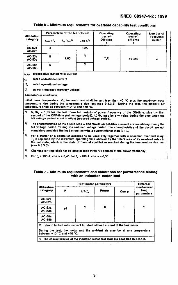
Table 6- Minimum requirements for overload capability test conditions—
Parameters of the test circuit—.
Operating OperatingUtilization
Number ofcycleg) cycleg)
categoryoperatinrj
/LRp/ /e (/,/ Uel) Cos q)a ON-time off time cycless s
AC-52S—
4 0,65AC-52b
AC-53a 8 5)
AC-53b 1,05 TX3) <1440 3
AC-56a 6 5)
AC-56b
LRP Prospective locked rotor currant
a ratad operational currant
Ye mted operational voltage
Lrr power fraquancy racovery voltage
Temperatuns conditions:
nitial case temperature, Cl, for aach tast shall be not lass than 40 “C plus the maximum casa:empemture rise during the temperature rlsa test (see 9.3.3.3). During the test, the am biant airtemperature shall be between +10 “C and +40 “C.
1) Ur /Ue = 1,05 for the last three full periods of power frequency of the ON-time, plus the, firstsqcond of the OFF-tima (full voltage period). L/r/Ue may be any valua during the time when thefuh voltaga period is not in effect (reduced voltage period).
?) The characteristics of the circuit (COSITIand maximum poaaible currant) are mandatory during thefull voltage period. During the reduced voltage period, the characteristics of the circuit are notmandatory providad the load circuit permitsa currenthigherthan X x le.
j) For a starter or a controller intanded to be used only together with a specified overload relay,Tx is replaced by tha maximum operating time allowad by the tolerances of its overload relay intha hot state, which is tha state of thermal equilibrium raachad during the tamperatura rise test(saa 9.3.3.3).
~) Changeover time shall not be graatar than threa full periods of tha powar frequanoy.
5) For /e s 100 A: coa v = 0,45, for /e >100 A: COSq = 0,35.
Table 7- Minimum requirements and conditions for performance testingwith an induction motor load
Test motor parameters ExternalUtilization mechanicalcategory K Ullle Power Coa ~ load
parameters, ,AC-52aAC-52b
F1AC-53a 24 1) 1) 1) 1)AC-53b
AC-58aAC-56b
IK ratio of Iockad rotorcurrantto ratadfullloadcurrentof thetest motor. I
During tha test, tha motor and the ambient air may be at any tempemturebetwaen +10 “C and +40 “C. I1) The characteristics of the induction motor test load are specmd in 8.2.4.3.
31

lS/lEC 60947-4-2:1999
8.2.4.2 Making and breaking capacities for devices in the main circuit I8.2.4.2.1 General IThe controller or starter, including the over-current releases and the mechanical switchingdevices associated with it, shsll be capsble of operating without failure in the presence oflocked rotor motor current (starting current snd overload current).
The capability of making and breaking currents without failure, shall be verified under theconditions stated in both tsble 8 and table 9, for the required utilization categories, and thenumber of operations indicated.
8.2.4.2.2 Series mechanical switching devices o? hybrid controllers IThe series mechanical switching devices in the main circuit of controllers and starters shallmeet the requirements of their own product standards, and the additional requirementsof 8.2.4,2 when tested aa a stand-alone device.
For bypassed hybrid controllers and starters (see figure 1), the series mechanical switchingdevice may be designated with a duty rating that IS aligned with the intermittent duty rating(e.g. AC-53b) of the semiconductor controller.
The making and brealdng capacity shall be verified by the procedures of 9.3.3,5 and 9.3.3.5.1. I8.2.4.2.3 Type tested, parallel mechanical switching devices of bypassed controllers IThe making and breaking capacity shall be verified when tested as a stand-alone device inaccordance with the procedures of 9.3.3.5 and 9.3.3.5.2.
6.2.4.2.4 Dependent, parallel mechanical switching devices of bypassed controllersI
The making and breaking capacity shall be verified when tested as a combined unit inaccordance with the procedures of 9.3.3.5 and 9.3.3.5.3.
8.2.4.2.5 Semiconductor switching devices
The capability to control overload currents shall be verified by the procedures of 9.3.3.6.2and 9.3.3.6.3.
8.2.4.3 Requirements for an induction motor test load
The induction motor test load shall feature a four-pole squirrel cage motor with the followingcharacteristic=
a) the rated voltage of the motor shall be equal to or greater than U. for the device to betested;
b) when the motor is running, the test current through the motor and the controller may beany value greater than 1 A;
c) the power factor of the motor may be of any value;
d) the inner connections of the motor windings may be of any configuration (e.g. star, delta);
e) the parameters of the mechanical load connected to the motor shaft shall be adjuated toproduce a decelerating time from base speed to zero speed within the range of 2s to 4 a.
32

y“
1lS/lEC 60947-4-2:1999
Table 8- Making and breaking capacity test; making and breaking conditionsaccording to utilization categories for the mechanical switching device
of hybrid motor controllers HI, H2, H3 and for certain formsof bypassed controllers
I Make and break conditions
UtilizationlJlm UJU* ON-time OFF-time
Numbercategory Cos q of operating
s s cycles
AC-52a, b 4,0 0,65
~ ’05m 0’05 2) “/c = currentmade and broken,
expressed in a.c. r.m.ssymmetrical valuaa
/. m ratad operational current
U, = rated operational voitage
U, = powerfrequencyrecoveryvoltege
1) f=or IeS 100A: COS q = 0.45
For /e> 100 A: Cos q = 0,35Z) OFF.Ume shall not be greater than
the values given in the chart.
Current /c
A
Jc< 100Iooclcszoo
200 ~ It s 300
300< Ic$400
400< ic<600
600 c /c< 600
600< IC< 1000
1000< ICS 1300
1300< ICS 1600
1600< /.
OFF-time
s
1020
30
40
60
60
100
140
160
240
Table 9- Conventional operational performance making and breaking conditionsaccording to utilization categories for the mechanical switching device
of hybrid motor controllers HI B, H2B, H3B and for certain formsof bypassed controllers
I Make and break conditions I
UtilizationLJ1. ON-time OFF-time
Number
category LIJU* Cos q of operatings s cycles
AC-52a, b 2,0 1,05 0,650,05
2)
AC-53a, b 2,0 1,05 1) 6000
AC-56a, b 6,0 1,05 0,35 56001: 9: 100
/c = current made and broken, axpressed in a.c. r.m.s. symmetrical valuas
/e = rated operational current
U@= rated operational voltage
Ur = power frequency recovery voltage
1) For \eS 100 A: COS q = 0,45
For /e> 100 A: Cos p = 0,35
2) oFF.tlrnaa shall not be greater than the Valuea gtien in tabla 6.
33

!W!EC 60947-4-2:1999
t~.ii 5 Go-ordination with short-circuit protective devices
::.;. 3.1 Performance under short-circuit conditions..
-?Ifi rated conditional short-circuit current of controllers and starters backed Up by short-circuit~{ti,,ice(s) (SCPDS) shall be verified by short-circuit tests as specified in 9.3.4. These teStS are
mandatory,
“The rating of the SCPD shall be adequate for any given rated operational current, ratedoperational voltage and the corresponding utilization category.
Two types of co-ordination are permissible, type 1 or type 2. Test conditions for both aregiven in 9.3.4.3.
Type 1 co-ordination requires that, under short-circuit conditions, the device shall cause nodanger to persons or installation and may not be suitable for further service without repair andreplacement of parts.
Type 2 co-ordination requires that, under short-circuit conditions, the device shall cause nodanger to persons or installation and shall be suitable for further use. For hybrid controllersar!d starters, the risk of contact welding is recognized, in which caae the manufacturer shallIndicate the measures to be taken as regards the maintenance of the equipment.
NOTE Use of a SCPD not h compliance with the manufacturer’s recommendation may hwalidete the Co-ordination,
8.2.5.2 Discrimination between overload relays and SCPDS
‘rt?is may be verified by a special test (see 9.1.5).
8.2.6 Switching overvoltages
Under consideration.
8.3 EMC requirements
8.3.1 General
it is widely accepted that the achievement of electromagnetic compatibility between differentitems of electrical and electronic apparatus is a desirable objective. Indeed, in manycountries, mandatory requirements for EMC exist. The test levels and requirements to achievean acceptable level of EMC are given in clauses 8 and 9.
The requirements specified in the following subclauses are included to permit theachievement of electromagnetic compatibility for controllers and starters. All relevantimmunity and emission requirements are covered, and additional tests are not required ornecessary. EMC performance is not guaranteed in the event that the controller or starter issubject to electronic component failure. These conditions are not considered, and do not formpart of the test requirements.
All phenomena, whether emission or immunity, are considered individually: the limits givenare for conditions which are not considered to have cumulative effects.
34
lS/lEC 6094742:1999
Controllers and starters are complex devices which must be interconnected with otherequipment (such as motors, cables, etc. ) to form a system. Because the other equipment orthe interconnections may not be under the control of the manufacturer of the controller orstarter, controllers and starters shall be characterized as stand-alone devices by the testsdescribed herein, conducted either at the manufacturer’s premises, or at a test laboratory atthe manufacturers choosing. It shall be the responsibility of the system integrator (who mayalso be the manufacturer of controllers and starters) to ensure that systems containingcontrollers or starters comply with the requirements of any rules and regulations applicable.
These clauses do not describe or affect the safety requirements for a controller or startersuch as protection against electric shocks, insulation co-ordination, and related dielectrictests, unsafe operation, or unsafe consequence of a failure.
The emission limits specified may not provide full protection against interference to radio andtelevision reception when the controller or starter is used closer than 10 m to the receivingantenna(e).
8.3.2 Emission
According to CISPR 11, there are two equipment classes
Class A equipment is the usual class, and is intanded for use in industrial environments.
Equipment installed in a location covered by this classification is not directly connected to apublic low-voltage distribution network but is considered to be connected to an industrialpower distribution network with a dedicated distribution transformer.
Where class A equipment standards are insufficient for a particular industrial environment, as,for example, when sensitive measurement channels may be affected, then the user shallspecify class B equipment.
A suitable label shall be attached to any class A controller or starter advising that its usewithin a domestic environment could give rise to radio interference, for example:
ATTENTION
This product has been designed for class A equipment. Use of the product in domesticenvironments may cause radio interference, in which case the user may be required toemploy additional mitigation methods.
If it is not possible to attach the label to the product, the manufacturer may have the option topresent this’ information in the user information, with the provision that the information shall bedisplayed in a manner that is conspicuous.
Class B equipment is to be specified, when it is to be installed in commercial or light industrialpremises, connected directly to the public low-voltage distribution network.
The equipment class shall be stated by the manufacturer in the user information.
35

i
..,.1.* ——
lS/lEC
8.3.2.1
60947-4-2:1999
Low-frequency emission with reference to main power frequency
8.3.2.1.1 Harmonics
Controllers or starters rated less than 16 A and connected ‘to the public low-voltagedistribution network, shall comply with the requirements of IEC 61000-3-2, Controllers orstarters not within the scope of IEC 61000-3-2 are under consideration, Tests are not requiredon controllers or starters which run in the FULL-ON state, for example forms 2 and 3 andcertain form 1 controllers or starters, because the harmonic emissions are of short durationduring starting, and there are no significant harmonic emissions in the FULL-ON state,
8.3.2.1.2 Voltage fluctuation
This phenomenon does not arise from the action of a controller or starter, therefore no testsare required.
8.3.2.2 High-frequency emission
8.3.2.2.1 Conducted radio-frequency (RF) emission
The limits given in table 14 shall be verified in accordance with the procedures of 9.3.5.1.1.
8.3.2.2.2 Radiated emission
The limits given in table 15 shall be verified in accordance with the procedures of 9.3.5.1.2.
8.3.3 Immunity
8.3,3.1 General
Electrical system influences may be destructive or non-destructive, depending on the intensityof the influence, Destructive influences (voltage or current) cause irreversible damage to acontroller or starter. Non-destructive influences may cause temporary malfunction orabnormal operation, but the controller or starter returns to normal operation after the influenceis minimized or removed; in some cases, this may require manual intervention,
The manufacturer should be consulted in those instances where severe external influencesmay occur, which are greater than the levels for which the controller or starter has beentested, for example installations in remote locations with long power transmission lines; closeproximity to ISM equipment as defined in CISPR 11.
NOTE The careful application of decoupling practices during installation halps to minimize the external transientinfluences. For example, control circuit wiring should be separated from power circuit wiring. Where closelycoupled wiring cannot be avoided, twisted pairs or shielded wiring should be used for control circuit connections.
?
A number of requirements are listed. The test results are specified using the performancecriteria of the IEC 61000-4 series. For convenience, the performance criteria are quoted here,and described in more specific detail in table 10.
36

‘1,’
lS/lEC 60947-4-2:1999
These are:
1) Normal performance within the specification limits.
2) Temporary degradation, or loss of function or performance, which is self-recoverable.
3) Temporary degradation, or loss of function or performance which requires operatorintervention or system reset. Normal functions must be restorable by simple intervention,such as by manual reset or restart. There must not be any damaged components.
In table 10, the acceptance criteria are described for overall performance (A), which are usedwhen a complete controller or starter is tested. When it is not possible to test the completecontroller or starter, the functional element performances (B, C,D) are to be used.
Table 10 – Specific acceptance or performance criteriawhen EM disturbances are present
Acceptance criteria
Item (performance during test)
1 2 3
A Overall performance No noticeable changes of Noticeable changes Changes in operatingthe operating characteristic (visual or audible) of the characteristicOperating as intended operating characteristic Triggering of protectivedevices
Self-recoverable Not self-recoverable
B Operation of power No maloperation Temperary maloperation Shut downand drivingcircuits which cannot cause tripping, Triggering of protactkredevices
or erratic and audible Not self-recoverablechenges in motortorque
C Operation of displays No changes to visible display Temporary visible changes Shut downand control panels information or loss of information Permanent lossor displey
Only slight light intensity Undesired LED illumination of wrong informationfluctuationof LEDs, or slight Unpermitted opareting modemovement of characters not self-recoverable
D Informationprocessing Undisturbed communication Temporarily disturbed com- Erroneous processingand sensing functions and data interchangeto munication,with possible of information
external devices error reports of the internal Loss of data and/or informationand external devices Errors in communication
Not self-recoverable
8.3.3.2 Electrostatic discharge
The test values and procedures are given in 9,3.5.2.1.
8.3.3.3 Radio-frequency electromagnetic field
The test values and procedures are given in 9.3.5.2.2.
8.3.3.4 Fast transients (common mode) (5/50 ns)
The test values and procedures are given in 9.3.5.2.3.
8.3.3.5 Surges (1,2/50/IJs-8/20/ps)
The test values and procedures are given in 9.3.5.2.4.
37

lS/lEC 60S4742:1999
8.3.3.6 Harmonics and commutation notches
The test values and procedures are given in 9.3.5.2.5.
8.3.3.7 Voltage dips and short time interruptions
The test valuea and procedures are given in 9.3.5.2.6,
8.3.3.8 Power frequency magnetic field
Tests are not required. Immunity is demonstrated by the successful completion of thaoperating capability test (see 9.3.3.6).
9 Tests
9.1 Kinds of tests
%1.1 General
Subclause 8.1.1 of IEC 60947-1 applies.
9.1.2 Type tests
Type tests are intended to verify compliance of the design of controllers and starters of allforms with this standard. They comprise the verification of:
a) temperature-rise limits (9.3.3.3);
b) dielectric properties (9.3.3.4);
c) operating capability (9.3.3.6);
d) operation and operating limits (9.3.3.6.3);
e) rated making and breaking capacity and conventional operational performance of seriasmechanical switching devices of hybrid equipment (9.3.3.5);
f) performance under short-circuit conditions (9.3.4);
g) mechanical properties of terminals (8.2.4 of IEC 60947-1 applies);
h) degrees of protection of enclosed controllers and starters (annex C of IEC 60947-1applies);
i) ElktC tests (9.3.5).
9.1.3 Routine tests (9.3.6)
Subclause 6.1.2 of IEC 60947-1 applies where sampling tests (9.1.4) are not made instead.
Routine tests for controllers and starters comprise:
- operation and operating limits (9.3.6.2);
- dielectric tests (9.3.6.3).
38

lS/lEC 60947-4-2:1999
9.1.4 Sampling tests (9.3.6)
Sampling tests for controllers and starters comprise:
- operation and operating limits (9,3.6.2);
- dielectric tests {9.3.6.3).
Subclause 8.1.3 of IEC 60947-1 applies, with the following amplification:
A manufacturer may use sampling tests instead of routine tests at his own discretion.Sampling shall meet or exceed the following requirements, as specified in IEC 60410(see table II-A of IEC 60410).
Sampling is based on AQL <1:
- acceptance number Ac = O (no defect accepted);
– rejection number Re = 1 (if 1 defect, the entire lot shall be tested).
Sampling shall be made at regular intervals for each specific lot.
Alternative statistical methods that ensure compliance with the above IEC 60410 require-ments can be used, for example statistical methods controlling continuous manufacturing orprocess control with capability index.
Sampling tests for clearance verification according to 8.3.3,4.3 of IEC 60947-1 are underconsideration.
9.1.5 Special tests (9.4)
Special tests for controllers and starters comprise:
- discrimination between overload relays and SCPDS (see annex C).
9.2 Compliance with constructional requirements
Subclause 8,2 of IEC 60947-1 applies (however, see
9.3 Compliance with performance requirements
9.3.1 Test sequences
Each test sequence is made on a new sample.
note to 8.1).
NOTE 1 With the agreement of the manufacturer, more than one teat sequence, or all sequences, may beconducted on one sample. However, the tests are to be conducted in the sequence given for each sample.
NOTE 2 Some tests are included in the sequences solely to reduce the number of samples required; tha resultshave no significance for the preceding or following teats in the sequence. Therefora, for convenience of testing andby agreement with the manufacturer, these tests may be conducted on separate new samples and omitted from therelevant sequence. This only applies to the following tests when called for:
&3.3.4. 1 item 5) of IEC 60947-1: Verification of craapage distance;
6.2.4 of IEC 60947-1: Mechanical properties of terminals;
annex C of IEC 60947-7: Oagraes of protection of enclosed equipment.
39

.
I
I
1
lS/lEC 60947-4-2:1999
The test sequence shall be as follows:
a) Test sequence /
i) Verification of temperature rise (9.3.3.3)
ii) Verification of dielectric properties (9.3 3.4)
b) Test sequence 11: Operating capability verification (9.3.3.6)
i) Thermal stability test (9.3,3.6.1)
ii) Overload capability test (9.3.3.6.2)
iii) Blocking and commutating capability test (9.3.3.6,3), including verification of operationand operating limits
c) Test sequence Ill
i) Performance under short-circuit conditions (9.3.4)
d) Test sequence IV
i) Verification of mechanical properties of terminals (8.2,4 of IEC 60947-1)
ii) Verification of degrees of protection of enclosed equipment (annex C of IEC 60947-1)
e) Test sequence V
EMC tests (9.3.5)
9.3.2 General test conditions
Subclause 8,3,2 of IEC 60947-1 applies, with the following addition:
Unless otherwise specified in the relevant test clause, the clamping torque for connectionsshall be that specified by the manufacturer or, if not specified, the torque given in table 4 ofIEC 60947-1,
In the case where several heat sinks are specified, the one which has the higher thermalresistance shall be used.
True r.m, s, voltage and current measuring means shall be used.
9.3.3 Performance under no load, normal load, and overload conditions
9.3.3.1 Vacant
9.3.3.2 Vacant
9.3.3.3 Temperature rise
9.3.3.3.1 Ambient air temperature
Subclause 8.3.3.3.1 of IEC 60947-1 applies.
9.3.3.3.2 Measurement of the temperature of parts
Subclause 8.3.3.3,2 of IEC 60947-1 applies.
9.3.3.3.3 Temperature rise of a part
Subclause 8.3,3,3.3 of IEC 60947-1 applies.
40

lS/lEC 60947+2:1999
9.3.3.3.4 Temperature rise of the main circuit
For semiconductor switching devices connected in the main circuit (see 8.2.2.4), temperaturesensing means shall be attached to the outer surface of the case of the semiconductorswitching device that is most likely to produce the highest temperature rise during this test.The final case temperature, Cf, and the final ambient temperature, Af, shall be recorded foruse in the test of 9.3.3,6.2.
For mechanical switching devices (see 8.2,2.4.2 and 8.2.2.4.4), temperature sensing meansshall be attached in accordance with the requirements of 8,3,3.3 of IEC 60947-1,
The main circuit shall be loaded as stated in 8.2.2.4.
All auxiliary circuits which normally carry current shall be loaded at their maximum ratedoperational current (see “5.6), and the control circuits shall be energized at their ratedvoltages.
Starters shall be fitted with an overload relay, complying with 5.7, and selected as follows:
non-adjustable relay:
the current setting shall be equal to the maximum operational current of the starter, andthe test shall be at this current;
— adjustable relay:
the maximum current setting shall be that which is nearest to, but not greater than, themaximum operational current of the starter.
For starters, the test shall be made with that overload relay for which the current setting isnearest to the maximum of its scale.
NOTE The selection method described above is designed to ensure that the temperature rise of these field wiringterminals of the overload relay, and the power dissipated by the atarter, are not leaa than those that will occurunder any combination of relay and controller. In casea where the effect of the overload relay on these valuea iainsignificant (as in solid-state overload relays), the teat current shall always be the maximum operational current ofthe starter.
9.3.3.3.5 Temperature rise of control circuits
Subclause 8.3.3.3.5 of IEC 60947-1 applies, with the following addition:
The temperature rise shall be measured during the test of 9.3.3.3.4.
9.3.3.3.6 Temperature rise of coils and electromagnets
Subclause 8.3.3.3.6 of IEC 60947-1 applies with the following addition:
Electromagnets of contractors or etarters intended for duty within semiconductor controllers orfor mechanical bypass switching means shall comply with 8.2.2.6 with rated current flowingthrough the main circuit for the duration of the test. The temperature rise shall be meaauredduring the test of 8.3.3.3.4.
9.3.3.3.7 Tern perature rise of auxiliary circuits
Subclause 8.3.3.3.7 of [EC 60947-1 applies, with the following addition:
The temperature rise shall be measured during the test of 9.3.3.3.4.
I
41

lS/lEC 60947-4-2:1999
9.3.3.4 Dielectric properties
9.3.3.4.1 Type tests
1) General conditions for withstand voltage tests
Subclause 8.3,3.4,1 1) of IEC 60947-1 applies except the last note. See also 8,2,3.
2) Verification of impulse withstand voltage
a) General
Subclause 8.3.3.4.1 2) a) of IEC 60947-1 applies
b) Test voltage
Subclause 8,3.3.4,1 2) b) of IEC 60947-1 applies with the following sentence added.
For any part for which the dielectric properties are not sensitive to altitude (e.g. opto-coupler, potted parts, etc. ) the correction factor for altitude is not applicable.
c) Application of test voltage
With the equipment mounted and prepared as specified in item 1) above, the testvoltage is applied as follows:
i) between all the terminals of the main circuit connected together (including thecontrol and auxiliary circuits connected to the main circuit) and the enclosure ormounting plate, with the contacts, if any, in all normal positions of operation;
ii) for poles of the main circuit declared galvanically separated from the other poles:between each pole and the other poles connected together and to the enclosure ormounting plate, with the contacts, if any, in all normal positions of operation;
iii) between each control and auxiliary circuit not normally connected to the maincircuitand
– the main circuit;
– the other circuits;
– the exposed conductive parts;
– the enclosure or mounting plate, which, wherever appropriate, may beconnected together;
iv) for equipment suitable for isolation, across the poles of the main circuit, the lineterminals being connected together and the load terminals connected together.The test voltage shall be applied between the line and load terminals of theequipment with the contacts in the isolated open position and its value shall be asspecified in item 1) b) of 7.2.3.1 of IEC 60947-1.
d) Acceptance criteria
Subclause 8.3.3.4.1 2) d) of IEC 60947-1 applies.
3) Power-frequency withstand verification of solid insulation
a) General
Subclause 8.3,3.4.1 3) a) of IEC 60947-1 applies.
b) Test voltage
Subclause 8.3.3.4.1 3) b) of IEC 60947-1 applies with the following sentence added atthe end of the first paragraph.
If an alternating test voltage cannot be applied due to the EMC filter components,which cannot easily be disconnected, a direct test voltage may be used having thesame value as the crest value of the projected alternating test voltage.
42

lS/lEC 6094742:1999
I
c)
d)
Application of test voltage
Subclause 8.3.3.4.1 3) c) of IEC 60947-1 applies with the two last sentences modifiedas follows:
The test voltage shall be applied for 5s, with the following conditions:
- in accordance with items i), ii) and iii) of 2) c) above;
- for hybrid semiconductor controller or starters, across the poles of the main circuit,the line terminals being connected together and the load terminals connectedtogether.
Acceptance criteria
Subclause 8.3.3.4.1 3) d) of IEC 60947-1 applies.
4) Power-frequency withstand verification after switching and short-circuit tests
a)
b)
c)
d)
General
Subclause 8.3.3.4.1 4) a) of IEC 60947-1 applies.
Test voltage
Subclause 8.3.3.4.1 4) b) of IEC 60947-1 applies.
Application of test voltage
Subclause 8.3.3.4.1 4) c) of IEC 60947-1 applies with the following sentence added atthe end of the paragraph.
The use of a metal foil, as mentioned in 8.3.3.4.1 1) of IEC, 60947-1, is not required.
Acceptance criteria
Subclause 8.3.3.4.1 4) d) of IEC 60947-1 applies.
5) Power-frequency withstand verification after humidity treatment
Subclause 8.3.3.4.1 5) of IEC 60947-1 applies.
6) Verification of d.c. withstand voltage
Subclause 8.3.3.4.1 6) of IEC 60947-1 applies.
7) Verification of creepage distances
Subclause 8.3.3.4.1 7) of IEC 60947-1 applies.
8) Verification of leakage current of equipment suitable for isolation
The maximum leakage current shall not exceed the values of 7.2.7 of IEC 60947-1.
9.3.3.4.2 Vacant
9.3.3.4.3 Sampling tests for verification of clearances
1)
2)
3)
4)
General
Subclause 8.3.3.4.3 1) of IEC 60947-1 applies.
Test voltage
The test voltage shall be that corresponding to the rated impulse withstand voltage.
Sampling plans and procedure are under consideration.
Application of test voltage
Subclause 8.3.3.4.3 3) of IEC 60947-1 applies.
Acceptance criteria
Subclause 8.3.3.4.3 4) of IEC 60947-4 applies.
43
lS/lEC 60947-4-2:1999
9.3.3.5 Making and breaking capacity of mechanical switching devices
It shall be verified that mechanical switching devices meet the requirements of 8.2,4.2.
If the mechanical switching device has not passed previous tests, compliance with thefollowing subclauses of 8.2.4.2 is required, The making and breaking capacity shall beverified in accordance with 8.3.3.5 of IEC 60947-1.
9.3.3.5.1 Series mechanical switching devices of hybrid controllers
a) The subject device may be tested as a separate component, or
b) the complete hybrid controller may be tested with the subject devices installed as innormal service and with the semiconductor components of each pole shorted out.
9.3.3.5.2 Type tested, parallel mechanical switching devices of bypassed controllers
The subject device shall be tested as a separate device.
9,3.3.5.3 Dependent, parallel mechanical switching devices of bypassed controllers I
The complete unit with bypass installed shall be tested as in normal service, The operationalsequence, to simulate starting and stopping, shall be the same as in normal service. I9.3.3.6 Operating capability
Compliance with the operating capability requirements of 8.2.4.1 shall be verified by thefollowing three tests:
– thermal stability test;
- overload capability test;
– blocking and commutation capability test
The tests simulate 8 h duty.
Connections to the main circuit shall be similar to those intended to be used when theequipment is in service. The control voltage shall be fixed at 110 ‘A of the rated control supplyvoltage, US..
If the controller within a starter has satisfied the requirements of a previous operatingcapability test, and meets the requirements for assigning ratings based on the results of testas given in 5.4.1, the starter need not be tested.
44
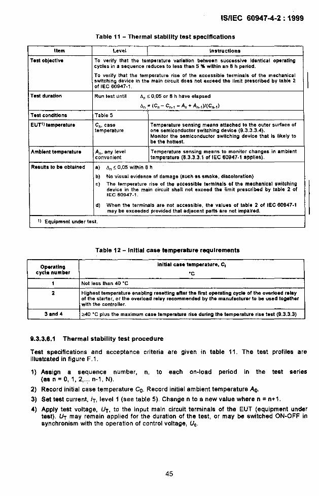
il
b
lS/IEC 60947-4-2:1999
Table 11- Thermal stability test specifications
Item I Level I Instructions I
objective
duration
condtions
1)temperature
To verify that tha temperature variation between succeaaive identical operatingcycles in a sequence reduces to leas than 5 % within an 8 h period.
To verify that the temperature rise of the accessible terminals of the mechanicalswitching device in the main circuit doas not exceed the limit prescribed by table 2of IEC 60947-1.
Run test until Ans 0,05 or 8 h have elapsed
An = (C. - C.., -A. + An.I) KCn-J
Table 5
Cn, casetemperature
Temperature sensing means attached to the outer surfaca ofone semiconductor switching device (9.3.3.3.4).Monitor the semiconductor switching device that is likely tobe the hottest.
ient temperature An, any level Temperature sansing means to monitor changes in ambientconvenient temperature (8.3.3.3.1 of IEC 60947-1 applies). I
ults to be obtained la) An<0,05within8h
I b) No visual evidence of damage (such aa smoke, discoloration)
c) The temperature rise of the accessible terminals of the mechanical switchingdevice in the main circuit shall not exceed the limit prescribed by tabla 2 ofIEC 60947-~.
d) When the terminals ara not accessible, the values of table 2 of IEC 80947-1may be exceeded provided that adjacant parts are not impaired.
Equipmant under tast.
I Operatingcycle number
11
Table 12- Initial case temperature requirements
initiai caae temperature, Cl
“c
Not less than 40 “C
Highest temperature enabling resetting after the first operating cycle of the overload relayof tha starter, or the overload relay recommended by the manufacturer to be used togetherwith the controller.
240 “C Plus the maximum case temperature rise during the temperature rise test (9.3.3.3)
9.3.3.6.1 Thermal stability test procedure
Teat specifications and acceptance criteria are given in table 11. The test profiles areillustrated in figure F. 1.
1)
2)
3)
4)
Aeaign a sequence number, n, to each on-load period in the test series(as n=O, 1, 2,..,. n-1, N).
Record initial case temperature Co. Record initial ambient temperature ACI.
Set te$t current, /T, level 1 (see table 5). Change n to a new value where n = n+l.
Apply test voltage, UT, to the input main circuit terminals of the EUT (equipment undertest). UT may remain applied for the duration of the test, or may be switched ON-OFF insynchronism with the operation of control voltage, Uc.
45

1,I
lS/lEC 60947+2:1999
Switch EUTto ON-state (EUT control voltage, Uc, is ON).
NOTE Thetime span of Txcommances at the instant when the test current reaches the value Xx /e. Therefore,the time for the test current ramp to reach X x /e increases the total test time. I
5a) This step applies to AC-52a, AC-53a, AC-58a only.After time interval Tx (table 5), change test current, /t, to level 2.After time interval for level 2, switch EUT to OFF-state.
5b) This step applies to AC-52b, AC-53b, AC-58b only.After time interval Tx (table 5), switch EUT to OFF-state.
6) Record case temperature Cn. Record ambient temperature An.
7) Decision to terminate (or continue) test:
a) Calculate case temperature rise change factor:
An = (Cn - Cn.l -An + An-t)/(Cn.1)
b) Check compliance with results to be obtained (table 11)
If & >0,05, tOM hSt time is less than 8 h, and results to be obtained (a) and b) oftable 11) are not violated, repeat steps 3 to 7.
If An >0,05, and total test time is greater than 8 h, or results to be obtained areviolated, end test. This is a failure.
[f An s0,05, and total test time is less than 8 h, and results a), b), c) and d) of table 11are not violated, end test. This is successful compliance. I
9.3.3.6.2 Overload capability test procedure
1) Teat conditions:
a) Refer to table 6. The test profile is represented in figure F.2,
b) Controllers and starters, utilizing a current controlled cut-out device in addition to anoverload relay to provide protection against overload conditions during running in theFULL-ON state, shall be tested with the cut-out device in place. In this test, it isacceptable for the cut-out device to switch the EUT to the OFF-state in a time shorterthan the specified ON-time.
2) .EUT adjustments
a) EUT shall be adjusted to minimize the time to establish the test current level, /LRp.
b) EUT fitted with a current-limit function shall be set to the highest value of X specifiedfor le.
cl Where the EUT is a starter, its overload relay shall be disabled, and Tx shall be set inaccordance with note 3 of table 6.
3) Test
a) Establish initial conditions.
b) Apply test voltage to the input main circuit terminals of the EUT.
(With form HxA, the series mechanical switching device contact is closed. With formHxB, the series mechanical switching device is open.)The test voltage shall be applied for the duration of the test.
c) Switch the EUT to ON-state.
d) After the ON-time (table 6), switch the EUT to the OFF-state.
NOTE In the case of form HxB, the OFF-state will be replaced by the OPEN-state.
46

I
e) Repeat steps
In the case(and possibly
lS/lEC 60947-4-2:1999
c) and d) twice. End test.
of the EUT having a current limit function during motor startingstopping), but not in the FULL-ON state, the overload capability test
procedure for verification of compliance of the EUT with the requirements of 8.2.4.1 isthe following:
i) After two operating c fcles as described above, the EUT is switched to the ON-state, and loaded with an initial test current /., not higher than /e.
ii) With the EUT in the FULL-ON state, the test circuit specified in table 6 isconnected to the load by means of an external switch. There shall be no currentinterruption during transition from current /0 to /LRP.
iii) In accordance with table 4, the test current /LRP is maintained for TX secondsbefore an OFF-state is established by the EUT. The EUT is, however, permitted toestablish -an OFF-state conditian at shorter times than Tx, provided it is equippedwith a suitable overload protection.
iiii) This operating cycle is performed twice.
The initial case temperature conditions for the required four operating cycles shall be asstated in table 12.
4) Verify the criteria (see 9.3.3.6.4)
a) No loss of commutating capability.
b) No loss of blocking capability.
c) No loss of functionality.
d) No visual evidence of damage.
Table 13- Blocking and commutating capability test specifications
Item Level instruction
Uumber of operating Test 1: 100 operating cycles with 85 % L/eand 85 % Us.:ycles Test 2: 1000 operating cycles with 110 % L/eand 110 % (/W
rest load The parameters of the induction motor and the mechanical load are given in table 7.
Tast instrument True r.m.s. current measuring means shall be connacted between the motor terminalsand the load side terminals on each pole of the EUT. The means shall be capable ofmeasuring currents in the range of milliamperes.
EUT temperature Room temperature (10 “C to 40 “C)
EUT settings EUT settings are limited to only those external adjusting maans provided by themanufacturer in the normal product offerings.
a) Controllers fitted with a current-limit function will be set at the lowest value of X thatwill allow the motor (as defined in table 7) to start.
b) Controllers fitted with ramp-start functions will be sat at the maximum ramping timeor 10 s, whichever is less.
initial values of starting current and/or starting voltage will be set at the minimum valuethat will allow the motor to start immediately.
Test cycle OB-time >time to achieve full voltaga and full speed + 1 s
OFF-time = 1/3 of the time for coasting to rest.
Results a) / A/ I <0,10 for each pole, where Al = ((F - 10)/ 10to be obtained
b) No visual evidence of damage (such as smoke, discoloration).
c) No loss of functionality as specified by the manufacturer.
I

lS/lEC 60947-4-2:1999
9.3.3.6.3 Blocking and commutating capability test
Test specifications are given in table 7 and table 13. The test profiles are shown in figure F.3
For form HxA, the contacts of the series mechanical switching device shall be maintained inthe closed position for the duration of the test.
For form HxB, the contacts of the series mechanical switching device may be operated toperform the testing cycles. However, the measurements of voltage across the poles shall beperformed with the series contacts closed, and with the semiconductor switching devices inthe OFF-state. The manufacturer shall provide instructions for fitting the EUT with specialfeatures that will permit compliance with the voltage measurement requirements.
1) The EUT shall be mounted and connected as in normal use with cable length between theEUT and test load not greater than 10 m.
2) The current measuring means shall be installed in a manner that is appropriate forrecording the values of the leakage current through the controller in steps 3) and 7).
if other auxiliary circuits or devices are connected in parallel with the semiconductorelements, care shall be taken in order to avoid measuring the parallel currents; only theleakage current of the semiconductor elements shall be measured and the means forobtaining those measures shall be installed accordingly.
3) With the voltages U. and Us applied to the EUT, and with the control voltage UC OFF,measure the current through each pole of the EUT and record these measurements as aset of initial data points, /0.
The test circuit shall remain closed from the start of step 4) through the completion ofstep 7). The current measuring means may be shorted by remote control means duringsteps 5) and 6), but it may not be removed by opening the circuit.
4) To start the test, the voltages Ue and Us (as specified in table 13) are applied to the EUTand maintained for the duration of the test through the completion of step 7).
5) By means of the control voltage, UC, cycle the EUT between the ON-state and OFF-stateas specified in table 13. If the controller does not perform as intended, or if evidence ofdamage develops, the test is discontinued, and considered a failure.
6) After the required number of operating cycles, turn UC to OFF with Ue and Us remainingON. Allow the EUT to return to the initial ambient temperature.
7) Repeat the current measurement procedure of step 3) and record as a set of final datapOintS, /F, corresponding tO the Set Of initial data pOintS, /0.
8) Calculate the variation of leakage current through each pole by means of the formula:
A/ = (/F – /()) / /0
9.3.3.6.4 Behaviour of the controller or starter during, and condition after,the operating capability tests
a) Commutating capabMty
If semiconductor devices do not commutate properly, the early stage of the failure mode isevidenced by degraded performance. Continued operation in this mode will cause thermalrunaway. The ultimate result will be excessive heating and loss of blocking capability.
48
I
b)
c)
d)
e)
lS/lEC 60947-4-2:1999
Thermal stability
Semiconductor devices subject to rapid operating cycles may not cool properly. The earlyeffects may initiate a thermal runaway condition leading to loss of blocking capability.
Blocking capability
Blocking capability is the ability to turn OFF and remain OFF whenever required.Excessive thermal stress will degrade blocking capability. The failure mode is evidencedby a partial or total loss of control.
Functionality
Some failure modes may not be catastrophic in the early stages. These failures areevident from gradual loss of funttion. Early detection and correction may preventpermanent damage.
Visual inspection
In the end, excessive thermal stresses due to elevated temperatures may cause per-manent damage. Visual evidence (smoke or discoloration) provides early warning ofultimate failure.
9.3.4 Performance under short-circuit conditions
This subclause specifies test conditions for verification of compliance with the requirements of8.2.5.1. Specific requirements regarding test procedure, teat sequence, condition of equip-ment after the test and types of co-ordination are given in 9.3.4.1 and 9.3.4.3.
9.3.4.1 General conditions for short-circuit tests
General conditions for short-circuit testa are aa follows:
“O operation: as a pre~test condition, the controller/etarter shall be sustained in the ON-stateby a dummy motor load. The pre-test current may be held at any arbitrary low level of currentthat is greater than the minimum load current (ace 3.1.11) of the controller/starter. The short-circuit current is applied to the controller/starter. by closing the shorting switch. The SCPD’shall interrupt the short-circuit current and the controller/starter shall withstand the let-throughcurrent;
“CO” operation for direct on-line equipment.
Initial case temperature shall not be less than 40 “C. In some caaes, it may be impossible topre-heat the EUT and maintain the initial case temperature at a teat site that ia fitted for short-circuit testing only. In these cases, tha manufacturer and user may agree to test the EUT atambient temperature. If used, the lower temperature shall be recorded in the test report.
9.3.4.1.1 General requirements for short-circuit tests
Subclause 8.3.4.1.1 of IEC 60947-1 applies.
49

lS/lEC 60947-4-2:1999
9.3.4.1.2 Test circuit fortheverification ofshort-circuit ratings
The test circuit of 8,3.4.1.2 of IEC 60947-1 shall be modified and wired as shown in figure 1.1of annex 1, The dummy motor load and the shorting switch shall have the followingcharacteristics:
a) the dummy load shall be a squirrel cage tnotor with the characteristics that are given in8.2,4.3;
b) the shorting switch (not a part of the EUT) shall be capable of making and carrying theshort-circuit current with no tendency to interfere with the process of applying the short-circuit current (e.g. bounce or other intermittent openings of the contacts). I
9.3.4.1.3 Power factor of the test circuit
Subclause 8,3,4.1.3 of IEC 60947-1 applies,
9.3.4.1.4 Vacant
9.3.4.1.5 Calibration of the test circuit
Subclause 8.3,4.1.5 of IEC 60947-1 applies.
9.3.4.1.6 Test procedure
Subclause 8.3.4.1.6 of IEC 60947-1 applies with the following additions:
The controller or the starter and its associated .SCPD shall be mounted and connected as innormal use, They shall be connected in the circuit using a maximum of 2,4 m of cable(corresponding to the operational current of the controller or starter) for each main circuit.
If the SCPD is separate from the controller or starter, it shall be connected to the starter usingthe cable specified above (the total length of cable shall not exceed 2,4 m).
Three phase tests are considered to cover single-phase applications.
The time-line for the test sequence is shown in figure 1.2. Ia) The test is started with the shorting switch in the open position (time TO).
Ib) The test voltage is then applied and the dummy motor load shall limit the current to a level
that is, at least, sufficient to maintain the controller in the ON-state (time Tl).
c) At any arbitrary time after the current through the controller has stabilized, the shortingswitch may then be closed at random and thereby establish a short-circuit current paththrough the EUT (time T2) which shall be cleared by the SCPD (time T3).
9.3.4.1.7 Vacant
9.3.4.1.8 Interpretation of records
Subclause 8.3,4,1.8 of IEC 60947-1 applies.
50

,’
‘1
I
,!
lS/lEC 60947-4-2:1999
9.3.4.2 Discrimination between overload relays and SCPDS
Special test. See annex C for details.
9.3.4.3 Conditional short-circuit current of controllers and starters
The controller or starter and the associated SCPD shall be subjected to the tests givenin 9.3.4.3.1.
No further testing is required for bypassed controllers with independent components. IBypassed controllers having dependent components shall be submitted to two separate short-circuit tests in accordance with 9.3.4.
a) Test 1: The test is conducted with the semiconductors in the conducting mode and withthe bypass contacts open. This is intended to simulate short-circuit conditions occurringwhile starting in a mode that is controlled by the semiconductors.
b) Test 2: The test is conducted with the semiconductors bypassed with the bypass contactsclosed. This is intended to simulate short-circuit conditions occurring while thesemiconductors of the EUT are bypassed,
The tests are to be conducted under conditions corresponding to the maximum /e and themaximum Ue for utilization category AC-53a.
When the same semiconductor component is used for several ratings, the test shall beperformed under the conditions corresponding to the highest rated current /e.
The controls shall, be energized by a separate electrical supply at the specified controlvoltage. The SCPD used shall be as stated in 8.2.5.1.
If the SCPD is a circuit-breaker with an adjustable current setting, the test shall be carried outwith the circuit-breaker adjusted to the maximum setting for type 1 co-ordination and to themaximum declared setting for type 2 co-ordination.
During the test, all openinga of the enclosure shall be closed aa in normal service and thedoor or cover secured by the means provided.
A starter covering a range of motor ratings and equipped with interchangeable overload relayashall be teated with the overload relay with the highest impedance and the overload relay withthe lowest impedance together with the corresponding SCPDa.
The O operation shall be performed with the sample at /q. I
9.3.4.3.1 Test at the rated conditional short-circuit current/q
The circuit shall be adjusted to the prospective short-circuit current /q equal to the ratedconditional short-circuit current.
If the SCPD ia a fuse and the test current is within the current-limiting range of the fuse then,if possible, the fuse shall be selected to allow the maximum value of cut-off current (/C)(according to figure 3 of IEC 60269-1 ) and the maximum let-through P( values.
51

lS/lEC 60947-4-2:1999
Except for direct on-line controllers or starters, one breaking operation of the SCPD shall beperformed with the controller or starter in the fuli-ON state and the SCPD closed; the short-circuit current shall be switched on by a separate switching device.
For direct on-line controllers or starters, one breaking operation of the SCPD shall beperformed by closing the controller or starter on to the short circuit.
9.3.4.3.2 Results to be obtained
The controller or starter shall be considered to have passed the tests at the prospectivecurrent /q if the following conditions are met for the claimed type of co-ordination.
Both types of co-ordination:
a) The fault current has been successfully interrupted by the SCPD or the starter. In addition,the fuse or fusible element or solid connection between the enclosure and supply shall nothave melted.
b) The door or cover of the enclosure has not been blown open, and it is possible to open thedoor or cover. Deformation of enclosure is considered acceptable provided the degree ofprotection by the enclosure is not less than IP2X.
c) There is no damage to the conductors or terminals and the conductors have not beenseparated from the terminals.
d) There is no cracking or breaking of ,an insulating base to the extent that the integrity ofmounting of a live part is impaired.
Type 1 co-ordination
e) There has been no discharge of parts beyond the enclosure. Damage to the controller andoverload relay is acceptable. The starter or the controller may be inoperative after the test.
Type 2 co-ordination
f) No damage to the overload relay or other parts has occurred and no replacement of partsis permitted during the test. For hybrid controllers and starters welding of contacta ispermitted, if they are easily separated (e.g. by a screwdriver) without significantdeformation. In the case of welded contacts as described above, the functionality of thedevice shall be verified under the conditions of table 6 for the declared utilization categoryby carrying out 10 operating cycles (instead of 3).
g) The tripping of the overload relay shall be verified at a multiple of the current settihg andshall conform to the published tripping characteristics, according to 5.7, both bef&e andafter the short-circuit test.
h) The adequacy of the insulation shall be verified by a dielectric test on the controller orstarter. The test voltage shall be applied as specified in 9.3.3.4.1 4).
9.3.5 EMC tests
All emission and immunity tests are type tests, and shall be carried out under representativeconditions, both operational and environmental, using the manufacturer’s recommendedwiring practices, and including any enclosures specified by the manufacturer.
52

lS/lEC 60947-4-2:1999
All tests shall be made under steady-state conditions. A motor is required for the purpose oftesting. The motor and its connections are auxiliary equipment necessary for the execution ofthe tests, but do not form part of the equipment under test. Except for the purposes of theharmonic emission test, it is not necessary to load the motor. If the motor used in any test isof lower power than the intended power range of the controller or starter, it shall be so statedin the test report. Tests are not required on the power output port. Unless otherwise specifiedby the manufacturer, the length of the connections to the motor shall be 3 m.
Test reports are to give all the relevant information relating to the tests (for example loadconditions, cable dispositions, etc.). A functional description and a definition of specificationlimits for the acceptance criteria shall be provided by the manufacturer, and noted in the testreport. The test report shall include any special measures that have been taken to achievecompliance, for example the use of shielded or special cables. A list of auxiliary equipment,which, together with the controller or starter, comprises the equipment necessary to complywith the immunity or emission requirements, shall also be included in the report. The testsshall be carried out at the rated supply voltage Us and in a reproducible manner.
Form 1 controllers and starters, in which the power switching elements, for exemplethyristors, are not fully conducting during some or sII steady-state modes of operation, shallbe tested under conditions of minimum conduction chosen by the manufacturer to representthe operation of the controller or starter at the points of sustained maximum emission orsusceptibility (see 9.3.5.1).
9.3.5.1 EMC emission tests
9.3.5.1.1 Conducted radio frequency emission test
Descriptions of the test, the test method and the test set-up are given in CISPR 11.
It shall be sufficient to test two samples from a range of controllers of different power ratingswhich represent the highest and lowest power ratings of the range.
The emission shall not exceed the levels given in table 14.
The addition of high-frequency common mode filtering in the main power connections maycause unacceptable reductions in motor starting torque, or render invalid the concept ofunearthed or high impedance earthed distribution systems, as employed within processindustries, with implications for system safety.
If, in order to fulfil the emission levels given in table 14, filters are necessary but are not usedfor the above reasons, other precautions shall be taken in order not to exceed the emissionIevela given in this table.
53

lS/lEC 60947-4-2:1999
Table 14- Terminal disturbance voltage limits for conducted radio-frequency emission
Equipment class(network type) (indu~trial) (pu~lic)
Frequency dB (wV) dB (pV)MHz
dB (jAr) dO (pV)quasi-peak sverage quasi-pesk average
0,15 to 0,5 100 so 66 to 56 56 to 46(decrease with log (decrease with log
of frequency) of frequency)-,
0,5 to 5 86 76 56 46
5t030 90 to 70 80 to 60 60 50(decreasewith log (decreasewith log
of frequency) of frequency)
● Limits in accordancewith CISPR11,Group2.
9.3.5.1.2 Radiated radio frequency emission test
Descriptions of the test, the test method, and the test set-up are given in CISPR 11. Specifictest conditions are given in clause 2 of annex D.
NOTE in the USA, digital devices with power consumption less than 6 nW are exempt from RF emission tests.
It shall be suticient to test a single representative sample from a range of controllers orstarters of different power ratings.
The emission shall not exceed the levels given in tabie 15.
Tabie 15- Radiated emissions test limits
Field strengthFrequency band
Equipment claaa A* Equipment class B.
30 MHz to 230 MHz30 dB (pV/m) 30 dB (pV/m)
quasi-peak at 30 m quasi-paak at 10 m
230 MHz to 1000 MHz37 dB (pV/m) 37 dB (yV/m)
quasi-peak at 30 m quasi-peak at 10 m
● Equipment class A tests may be carried out at 10 m distance, with the limits raisedby 10 dB.
9.3,5.2 EMC immunity tests
Where a range of controllers or starters comprise similarly configured control electronics,within similar frame sizes, it is only necessary to test a singie representative sample of thecontroller or starter as specified by the manufacturer.
54

lS/lEC 60947-4-2:1999
9.3.5.2.1 Electrostatic discharges
Controllers or starters shall be tested using the methods of IEC 61000-4-2. Test levels of 4 kVcontact discharge or 8 kV air discharge shall be used with 10 positive and 10 negative pulsesapplied to each selected point, the time interval between each successive single dischargebeing 1 S. Tes-ts ,ar~ not required on power terminals. Discharges shall be applied only topoints which are accessible during normal usage.
The controller or starter shall comply with performance criterion 2
Tests are not possible if the controller or starter is an open frameof protection IPOO. In that case, the manufacturer shall attach athe possibility of damage due to static discharge.
9.3.5.2.2 Radio-frequency electromagnetic field
I
of table 10.
or chassis unit, or of degreelabel to the unit advising of
Radio-frequency electromagnetic field tests are divided into two frequency ranges: 0,15 MHzto 80 MHz and 80 MHz to 1 000 MHz. For the range 0,15 MHz to 80 MHz, the test methodsare given in IEC 61000-4-6. The test level shall be 140 dBpV (level 3).
The frequencies shall be selected by the manufacturer and stated in the test report. Thecontroller or starter shall comply with performance criterion 1 of table 10.
For the range 80 MHz to 1000 MHz, the test methods are given in IEC 61000-4-3, The testlevel shall be 10 V/m swept over the frequency range 80 MHz to 1000 MHz. The controllerand starter shall comply with performance criterion 1 of table 10.
Tests are not required where the controller is to be supplied as a component to be installed ina specific-purpose EMC metallic enclosure. In that case, the manufacturer shall provide awritten notice or instruction specifying the precautions to be taken whenever the enclosure isto be opened.
9.3.5.2.3 Fast transients (5/50 ns)
The controller or starter shall be tested using the methods of IEC 61000-4-4.
The ~est level for a.c. power lines shall be 2,0 kV/5,0 kHz via the coupling/decouplingnetwork. The test voltage shall be applied for 1 min.
Terminals for control and auxiliary circuits intended for the connection of conductors whichextend more than 3 m shall be tested at 2,0 kV/5,0 kHz by means of the coupling clamp. IThe controller or starter shall comply with performance criterion 2 of table 10.
9.3.5.2.4 Surges (1,2/50 ps-8/20 PS)
The controller or starter shall be tested using the methods of IEC 61000-4-5.
The test level for power terminals shall be 2 kV line-to-earth and 1 kV line-to-line.
55
I
I

lS/lEC 60947-4-2:1999
Terminals for control and auxiliary circuits intended for the connection of conductors whichextend more than 3 m shall be tested at 2,0 kV line-to-earth and 1,0 kV line-to-line. Tests arenot applicable to protected circuits.
The repetition rate shall be 1 per minute, with the number of pulses being five positive andfive negative.
The controller or starter shall comply with performance criterion 2 of table 10,
If the controller is required to operate in an installation which is less protected for exampleinstallation class 4 or 5 according to IEC 61000-4-5, this shall be specified by the user. In thiscase the test levels shall be 4 kV line-to-earth and 2 kV line-to-line.
9.3.5.2.5 Harmonics and commutation notches
Under consideration.
9.3.5.2.6 Voltage dips and short-time interruptions
The test methods of IEC 61000-4-11 shall be used to verify the requirements of test A.The method of verification of tests B and C is under consideration.
The criteria of table 16 shall be satisfied.
Table 16- Voltage dips and short-time interruption test
Test level PerformanceTest Duration
% U*”criterion
!Alol 5000 ms 13
B 40 100 ms Undar consideration
c 70 Half period Under consideration
I ● where UTrepresents L/eand/or tJ~as appropriate.
9.3.6 Routine and sampling tests
Routine tests are tests to which each individual controller or starter ia subjected, during orafter manufacture, to verify that it complies with the stated requirements.
9.3.6.1 General
Routine or sampling tests shall be carried out under the same, or equivalent conditions tothose specified for type tests in the relevant parts of 9.1.2. However, the limits of operationin 9.3.3.2 may be verified at the prevailing ambient air temperature and on the overload relayalone, but a correction may be necessary to allow for the normal ambient conditions.
56

ISIIEC 60947-4-2:1999
9.3.6.2 Operation and operating limits
It shall reverified that the equipment operates according tothe requirements of 8.2.1.2 and8.2.1.5.
The functionality specified in 8.2.1.2 shall be verified by a blocking and commutatingcapability test according to table 7 and 9.3.3.6.3. Two operating cycles are required, one at85 ?40 (Je with 85 %’. Us, and one at 110 % Ue with 110 Y. Us.
Tests corresponding to the requirements of 8.2.1.5 may be made at only one chosenrepresentative current (which may be “different from those given in this standard), at anyconvenient voltage. This test may be a single test’ with all poles equally energized at thiscurrent to check that the tripping time conforms (within tolerances) to the curves supplied bythe manufacturer.
9.3.6.3 Dielectric tests
The metal foil need not be applied, The tests shall be conducted on dry and clean controllersand starters.
Verification of dielectric withstand may be performed before final asaembly of the device(that is, before connecting sensitive devices such as filter capacitors).
1)
2)
3)
Irepulse withstand voltage
Subclause 8.3.3.4.2 1) of IEC 60947-1 applies.
Power-frequency withstand voltage
Subclause 8.3.3.4.2 2) of IEC 60947-1 applies.
Combined impulse voltage and power-frequency withstand voltage
The tests of items 1) and 2) above may be replaced by a single power-frequencywithstand test where the peak value of the sinusoidal wave corresponds to tha valuestated in items 1) or 2), whichever is the higher.
9.4 Special tests
9.4.1 Discrimination between overload relays and SCPDS
Details are given in annex C.
57

lS/lEC 60947-4-2:1999
Annex A(normative)
Marking and identification of terminals
A,l General
The purpose of identifying terminals is to provide information regarding the function of eachterminal, or its location with respect to other terminals, or for other use.
A.2 Marking and identification of terminals of semiconductor controllersand starters
A.2. I Marking and identification of terminals of main CirCUitS
The terminals of the main circuits shall be marked by single figure numbers and analphanumeric system.
Table A.1 - Main circuit terminal markings
I Terminals I Markings I
I 1 lIL1-21TI 1
Main circuit31L2-41T25/L3-6/T371L4-81T4
For particular types of controllers or starters (see 5.2.5.3), the manufacturer shall provide thewiring diagram.
A.2.2 Marking and identification of terminals of controi circuits
A.2.2.1 Control circuit power supply terminals
Under consideration.
A.2.Z2 Control circuit input/output signal terminais
Under consideration.
A.2.3 Marking and identification of auxiliary circuits
The terminals of auxiliary circuits shall be marked or identified on the diagrams by two figurenumbers:
- the unit is a function number;
- the figure of the tens is a sequence number,
-58:

lS/lEC 60947-4-2:1999
The following examples illustrate such a marking system:
Sequencenumber
y’”’:’
A.2.3.I Functiomnumber
Function numbers 1, 2 are allocated to circuits with break contacts and function numbers 3, 4to circuits with make contacts.
NOTE The definitionsfor make contactsand break contactsare given in 2.3.12 and 2.3.13 of IEC 60947-1.
Examplas:
NOTE The dots in the above examples take tha place of the sequence numbers, which should be addedappropriately to the application.
The terminals of circuits with change-over contact elements shall be marked by the functionnumbers 1, 2 and 4.
II
●1
●>—●2
Function numbers 5 and 6 (for break contacts) and 7 and 8 (for make contacts) are allocatedto terminals of auxiliary circuits containing auxiliary contacts with special functions.
Examples: .
I I
9+86 I
●7 ●8
&-
—
Break contactdelayed on closing
Make contactdelayed on closing
The terminals of circuits with change-over contact elements with specialmarked by function numbers 5, 6 and 8..
59
functions shall be

lS/lEC 60947-4-2:1999
Example:
Change-overcontactdelayed in bothdiretilons
A.2.3.2 Sequence number
Terminals belonging to the same contact element shall be marked by the same sequencenumber.
All contact elements having the same function shall have different sequence numbers,
The sequence number may be omitted from the terminals only if additional informationprovided by the manufacturer clearly gives such a number.
Examples:
Four contactelements Threacontactelements
A.3 Marking and identification of terminals of overload relays
The terminals of the main circuits of overload relays shall be marked in the same manner asthe terminals of the main circuits of controllers and starters (see A.2.1).
The terminals of the auxiliary circuits of overload relays shall be marked in the same manneras the terminals of the auxiliary circuits of controllers and starters with specified functions(see A.2.3).
The sequence number shall be 9; if a second sequence number is required, it shall be O.
Examples:
II
*
21T1 l/Ll4/T2 3/L2
6/T3 5A-3
r-+
4
Alternatively, terminals may be identified on the wiring diagram supplied with the device.
60

lS/lEC 60947-4-2:1999
Annex B(normative)
Overload relays or releases
B.1 Characteristics of overload relays and releases
NOTE In the remainder of this standard, the words “overload relay” should be taken to apply equally to anoverload relay or an overload releasa, as appropriate.
B.1.l Summary of characteristics
The characteristics of relays and releases shall be stated in the following terms, wheneverapplicable:
- types of relay or release (see B.1 .2);
- characteristic values (see B.1 .3);
- designation and current settings of overload relays (see B.1.4);
B. ‘
time-current characteristics of overload relays (see B.1 .5);
influence of ambient air temperature (see B. I.6).
.2 Types of overload relay or release
They are time-delay relay types, the time-lag of which is:
a) dependent on previous load (such as thermal overload relay);
b) dependent on previous load (such as thermal overload relay), and alao sensitive to phaseloss (see 3.1.21).
NOTE The overload relay may also provide other protective functions; in such casas the manufacturer shallspecify the corresponding characteristics.
B.I.3 Characteristic values
designation and current settings (see B. 1.4);
rated frequency, when necessary (for example in the case of a current transformeroperated overload relay);
time-current characteristics (or range of characteristics), when necessary;
trip class according to classification in table B.1, or the value of the maximum trippingtime, in seconds, under the conditions specified in B.2. I.1, when this time exceeds 30s;
number of poles;
nature of the relay: for example, thermal or solid state.
61
I
I
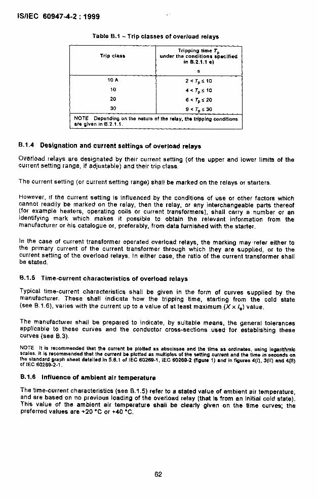
60947-4-2:1999
Table B.1 - Trip classes of overload relays
Tripping time TPTrip class under the conditions specified
in B.2.1.1 e)
s
10 A 2< TPS10
10 I 4< TPS10
20 I 6< TPS20
30 9< TP<30
NOTE Depending on the nature of the relay, the tripping conditionsare given in 6.2.1.1.
B. 1.4 Designation and current settings of overload relays
0ver16ad relays are designated by their current setting (of the upper and lower limits of thecurrent setting range, if adjustable) and their trip class.
The current setting (or current setting range) shall be marked on the relays or starters.
However, if the current setting is influenced by the conditions of use or other factors whichcannot readily be marked on the relay, then the relay, or any interchangeable parts thereof(for example heaters, operating coils or current transformers), shall carry a number or anidentifying mark which makes it possible to obtain the relevant information from themanufacturer or his catalogue or, preferably, from data furnished with the starter.
In the case of current transformer operated overload relays, the marking may refer either tothe primary current of the current transformer through which they are supplied, or to thecurrent setting of the overload relays. In either case, the ratio of the current transformer shallbe stated.
B.I.5 Time-current characteristics of overload relays
Typical time-current characteristics shall be given in the form of curves supplied by themanufacturer. These shall indicate how the tripping time, starting from the cold state(see 6.1.6), varies with the current up to a value of at least maximum (Xx /e) value.
The manufacturer shall be prepared to indicate, by suitable means, the general tolerancesapplicable to these curves and the conductor cross-sections used for establishing thesecurves (see B.3).
NOTE It is recommended that the current be plotted as abscissae snd the time as ordinates, using logarithmicscales. [t is recommended that the current be plotted as multiples of the setting current and the time in seconds onthe standard graph sheet detailed in 5.6.1 of IEC 6026$)-1, IEC 60269-2 (figure 1) and in figures 4(l), 3([[) and 4(11)of IEC 60269-2-1.
B.1.6 Influence of ambient air temperature
The time-current characteristics (see B.1 .5) refer to a stated value of ambient air temperature,and are based on no previous loading of the overload relay (that is from an initial cold state).This value of the ambient air temperature shall be clearly given on the time curves; thepreferred values are +20 “C or +40 “C.
62

lS/lEC 60947-4-2:1999
The overload relays shall be able to operate within the ambient air temperature range of O “Cto +40 “C, and the manufacturer shall be prepared to state the effect of variation in ambientair temperature on the characteristics of overload relays.
B.2 Performance requirements
B.2.I Limits of operation of overload relays
B.2. 1.1 Limits of operation of time-delay overload relays when all poles are energized
The relays shall comply with the requirements of table B.2 when tested as follows:
a)
b)
c)
d)
e)
In
With the overload relay or starter in its enclosure, if normally fitted, and at A times thecurrent settin-g, tripping shall not occur in less than 2 h, starting from the cold state,at the value of reference ambient air temperature as stated in table B.2. However, whenthe overload relay terminals have reached thermal equilibrium at the test current in lessthan 2 h, the test duration can be the time needed to reach such thermal equilibrium.
When the current is subsequently raised to B times the current setting, tripping shall occurin less than 2 h.
For class IOA overload relays energized ‘at C times the current setting, tripping shall occurin less than 2 min starting from thermal equilibrium at the current setting, in accordancewith IEC 60034-1.
For class 10, 20 and 30 overload relays energized at C times the current setting, trippingshall occur in less than 4 rein, 8 min or 12 min respectively, starting from thermalequilibrium at the current setting.
The trip class classification corresponds to a test made at 7,2 times the current setting,starting from the cold state. This test current value may be replaced by a current valueequal to Xx /e, in such case the tripping time shall be:
- higher than or equal to the corresponding value given table 4; and
- lower than or equal to (7,2/X)z times the maximum tripping time, TP, of table B 1.
case of more than one declared rating index, X and TXare the values corresponding to therating index giving the highest product (Xle)z x Tx. ‘-
In the case of overload relays having a current setting range, the limits of operation shallapply when the relay is carrying the current associated with the maximum setting, and alsowhen the relay is carrying the current associated with the minimum setting.
For non-compensated overload relays the current multiple/ambient temperature characteristicshall not be greater than 1,2 ‘?40/K.
NOTE 1,2 %/K is the derating characteristic of PVC insulatad conductors.
An overload relay is regarded as compensated if it complies with the relevant requirements oftables B.2 and B.3 at +20 “C, and is within the limits shown in figure B.1 at othertemperatures.
63

——. ——.—— ———
,,
1!
I
I
I
lS/lEC 60947-4-2:1999
B.2.I.2 Limits of operation of three-pole overload relays energized on two poles
With reference to table B.3:
The overload relay or starter shall be tested in its enclosure if normally fitted. With the relayenergized on three poles, at A times the current setting, tripping shall not occur in less than2 h, starting from the cold state, at the value of the ambient air temperature stated intable B.3.
Moreover, when the value of the current flowing in two poles (in phase loss sensitive relaysthose carrying the higher current) is increased to B times the current setting, and the thirdpole de-energized, tripping shall occur in less than 2 h.
The values shall apply to all combinations of poles.
In the case of overload relays having an adjustable current setting, the characteristics shallapply both when the relay is carrying the current associated with the maximum setting, andalso when the relay is carrying the current associated with the minimum setting,
Table B,2 - Limits of operation of timedelay overload relayswhen energized on all poles
Type ofoverload relay
W ai~~~Hure
Not compensated for ambientair temperature variations 1,0 1,2 1,5 +40 “c
Compensated for ambientair temperature variations I 1,05 I 1,2
I1,5
I+20 “c I
Table B.3 - Llmlts of operation of three-pole overload relayswhen energized on two poles only
Multiples ofType of current setting Reference ambient
overload relayA I B
●ir tam perature
Compensated for ambient air 3-poles 2-poles +20 “ctemperature variations 1,0 1,32
I Not phasa loss sensitiva
=
Not compensated for ambient air
F3-poles
1,0
2-poles1,0
1-pole0,9
1-poleo
2-poles1,25
l-poleo
2-poles1,15
1-polao
+40 “c
+20 “c
64

lS/lEC 60947-4-2:1999
6.3 Operating limits test conditions
Overload relays and starters shall be connected using conductors in accordance withtables 9, 10 and 11 of IEC 60947-1 for test currents corresponding to:
- 100 ?4. of the current setting of the overload relay for overload relays of trip class 10A;
125 ‘Mo of the current setting of the overload relay for overload relays of trip classes 10, 20,and 30, and for overload relays for which a maximum tripping time greater than 30 s isspecified (see B. 1.3).
Overload relays with all poles energized shall be tested as stated in B.2. I.1.
Moreover, the characteristics defined in B.2. 1.1 shall be verified by tests at O ‘C, +20 ‘C,+40“c.
Three-oole overload relays energized on two poles only shall be tested as stated in B.2.1.2 on
I
all combinations ofadjustable setilngs.
poles and a~ the maximum and m-inimum
Standardrange
current setilngs for relays with
. 1 I I ., I I w 1
-lo 0 10 20 30 40 50 Oc
Ambientsirtemperature
Figure B.1 - Multiple of current setting Ilmlts for ambient air temperaturecompensated tlmedelay overload relays
65
IWEC 60947-4-2:1999
Annex C(normative)
Discrimination between overload protective devices and SCPDS
C.1 Discrimination between protective devices and SCPDS
C.1.l General
This annex states the method of verifying the performance of overload ,protective devices ofstarters and the associated SCP13S at currents above and below the cross-over point /c Of themean curves of their respective time-current characteristics and the correspmtilng typeS ofco-ordination described in 8.2.5.1.
when it is not possible to determine the overload protective time-current characteristics(for instance for some devices provided with a current limitation) the manufacturer shallnominate a test current value for /c (whether prospective or not).
C.1.2 Condition for the test
The starter and its associated SCPD shall be mounted and connected as in normal We.
AlI the tests shall be performed starting from cold state.
C. 1.3 Test currents and test circuits
The test circuit shall be according to 8.3.3.5.2 of IEC 60947-1 except that the Oscillatorytransient voitage need not be adjusted. The currents for the tests shall be:
a) 0,75 IC + O ‘k -5 ‘k and
b) I,251C +5%,0%.
The power-factor of the test circuit shall be in accordance with table 6. In the case of smallrelays having a high resistance, inductors should be mainly used in order to have a ValUr3 Of
power-factor as iow as possible. The recovery voltage shall be 1,05 times the ratedoperational voltage (Je.
The SCPD shall be as stated in 8,2.5.1 and of the same rating and characteristic aS used in‘the test of 9.3.4.3.
Un!ess otherwise specified by the manufacturer the control circuit shall be supplied frOm a‘separate source at the rated control aupp[y voltage. The starter shall be connected SO that itreverts to the OFF state (open state for a hybrid starter) when the overload prOtt3Cth/e deviceIoperates.
66
!S/lEC 60947-4-2:1999
C.2 Test procedure and results to be obtained
C.2. 1 Test procedure
With the starter and the SCPD closed, the test currents stated in C.I.3 shall be applied by aseparate closing- deviee.
In each case the device tested shall be at room temperature.
The SCPD shall be inspected and any overload protective devices or circuit-breaker releaseshall be reset. Fuses shall be replaced if any one of them has melted.
C.2.2 Results to be obtained
After the test at the lower current a) in C. I.3, the SCPD shall not have operated and theoverload protective device shall have operated to break the current. There shall be nodamage to the starter.
After the test at the higher current b) in C.I.3, the SCPD shall have operated before theoverload protective device. The starter shall meet the conditions of 9.3.4.3.2 for the type ofco-ordination stated by the manufacturer.
67

lS/IEC 60947-4-2:1999
Annex D(normative)
Requirements for radiated emission testing
D.1 Characteristics of controllers and starters
The main circuits of controllers and starters include semiconductors within, or in series with,the windings of an induction motor. The action of the semiconductors allows either a fixed orvariable amount of energy to pass from the supply to the motor by regulating the conductionperiods during one or more half periods of the supply. The fundamental frequency of thesupply fed to the motor is the same as that of the supply to the main terminals ofthe controller. The controller does not convert electrical energy from one form to another aspart of its process.
For the purposes of this annex, a controller or starter is considered as comprising thefollowing constituent assemblies:
the main circuits, which include the semiconductor switching elements through ‘whichenergy is imparted to the motor;
the control circuits, which incl,ude all the necessary components in which control functionsare generated;
the auxiliary circuits, which perform functions such as digital communication links andpower line carrier systems.
D.2 Radiated emissions
D.2.f Main power circuits
D.2.I.1 FULL-ON mode
In the FULL-ON mode, the voltage and current waveforms to the motor are virtuallysinusoidal, and are at the supply frequency. Since higher order harmonics cannot exist wherethe waveform is sinusoidal, RF emission testing of the power circuits is not required duringoperation in the FULL-ON mode.
D.2.1.2 Phase control mode
The only source of RF energy within the power circuits of a controller is the energy required toswitch the power semiconductor from a conducting state to a non-conducting state and viceversa. The nature of the switching is to ensure that the current will always be at or near zerowhenever switching occurs (that is naturally commutated); the switching energy is very smalland the capability to generate RF emissions is also very small. Therefore:
the ability to generate RF emissions is not related to the amount of current present in thepower circuits in the FULL-ON state, and is independent of the value of rated current, /e;
no radiation testing of the main circuits is required.
68

lS/lEC 60947-4-2:1999
D.2.2 Control and auxiliary circuits
For control and auxiliary circuits the following rules apply:
They may be considered separately from the power circuits.
As stated in CISPR 14 for similar devices, experience has shown that in semiconductorcontrollers, the disturbing energy is mostly radiated by the external leads connected to thecontroller. Therefore, for the purposes of this standard, the disturbing capability of a controllershall be defined as the high-frequency power it can supply to those leads.
Circuits that generate or operate with sinusoidal waveforms shall be tested if the highestfundamental frequency involved is 30 MHz or greater.
If none of the wires connected to a control or auxiliary circuit terminal contain a component ofpower which is greater than 18 nW (equipment class A) or 2,0 nW (equipment class B) at anyfrequency of 30 MHz or greater, no testing is required (see annex E).
69

ISIIEC 60947-4-2:1999
Annex E(informative)
Method of converting CISPR 11 radiated emission limitsto transmitted power equivalents
From well known and established principles including the Lorentz Theory of Reciprocity, thetransmitted power, PT, necessary to achieve the field strength specified by CISPR 11 can becalculated from:
PT = E2 dz130 G
where
PT is the transmitted power in watts;
E is the electromagnetic field strength in V/m;
G is the gain of the antenna (for an ideal half-wave dipole, G = 1,64);
d is the distance between the transmitting and receiving antennae in metres.
For d = 30 m and & = 31,6 pV/m (3O dBpV/m), PT = 18 nW
For d = 10 m and E = 31,6 ~V/m (30 dBpV/m), PT = 2 nW
From this it can be concluded that when an ideal half-wave dipole is properly connected toany source transmitter that can generate 18 nW or 2 nW, the radiated emission field strength
would equal the limits specified by CISPR 11 for class A and class B equipment respectively.
70
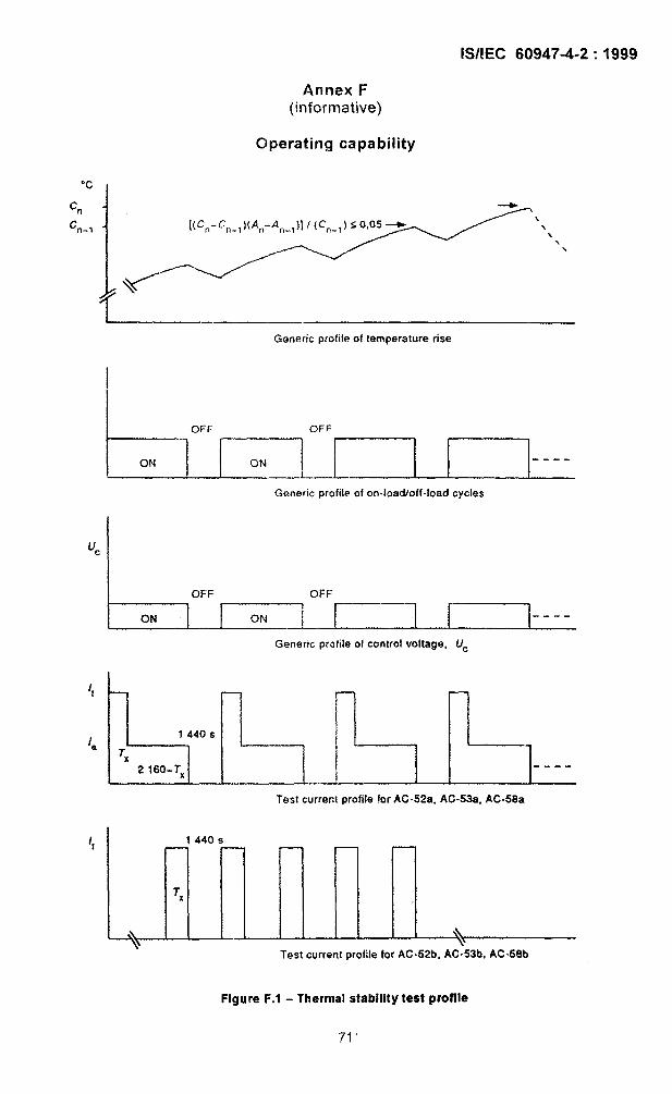
lS/lEC 60947-4-2:1999
Annex F
(informative)
Clperating capability
Generic profile of temperature rise
I
t-1OFF OFF
ON ON----
Generic profile of on-load/off40ad cycles
u=
OFF OFF
ON I ON 1 I [----
Generic profile of control voltage, Uc
7
1440 sL
Tx
2 160-TX----
Tesi current profile for AC-52a, AC-53a, AC-58a
1440 s
Tx
-+
\\
Test current profile for AC-52b, AC-53b, AC-58b
Figure F.1 - Thermal stability test profile
71 ‘
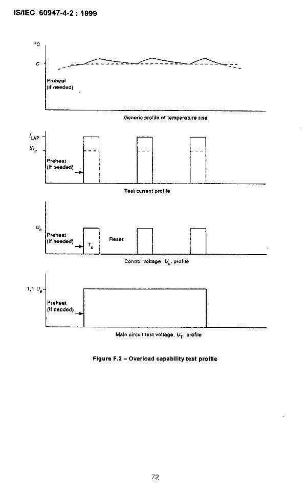
lS/lEC 60947-4-2:1999
“c
c L-————----------------L_L==~.
Preheat(if needed)
/LAP
Xle
Uc
Generic profile of temperature rise
-- --
- r--Preheat(if needed)
Test current profile
Preheat
Control voltage, Uc, profile
Main circuit test voltage. UT, profile
Ffgure F.2 - Overfoad capability test proffie
72

lS/lEC 60947-4-2:1999
113 of the timeto zero speed
Base +; ;tspeed
-/
Motor speed profile
Ue -
-----
Control voltage, UC.profile
Ue
/
L --l!L ‘---~Motor voltage prOfile
J!!_—
-----
Motor current profiie
Figure F.3 - Blocking and commutating capability test profile
73

lS/lEC 60947-4-2:1999
Annex G(informative)
Examples of control circuit configurations
G.1 External control device (ECD)
G.1.l Definition of an ECD
Any external element which serves to effect the control of the controller.
G.1.2 Diagrammatic representation of an ECD
❑ECD
–Y’-
Ri QR, z,
or
G.1.3 Parameters of an ECD
– Ri: internal resistance
– Zi: internal leakage impedance
NOTE In the case where ECD is a mechanical push button, Ri is often neglected and Z, is often taken as 00.
G.2 Control circuit configurations
G.2.I Controllers with external control supply
G.2.1.I Single supply and control input
A A
ECD
–/
Detice 1
H
* —
o,
74
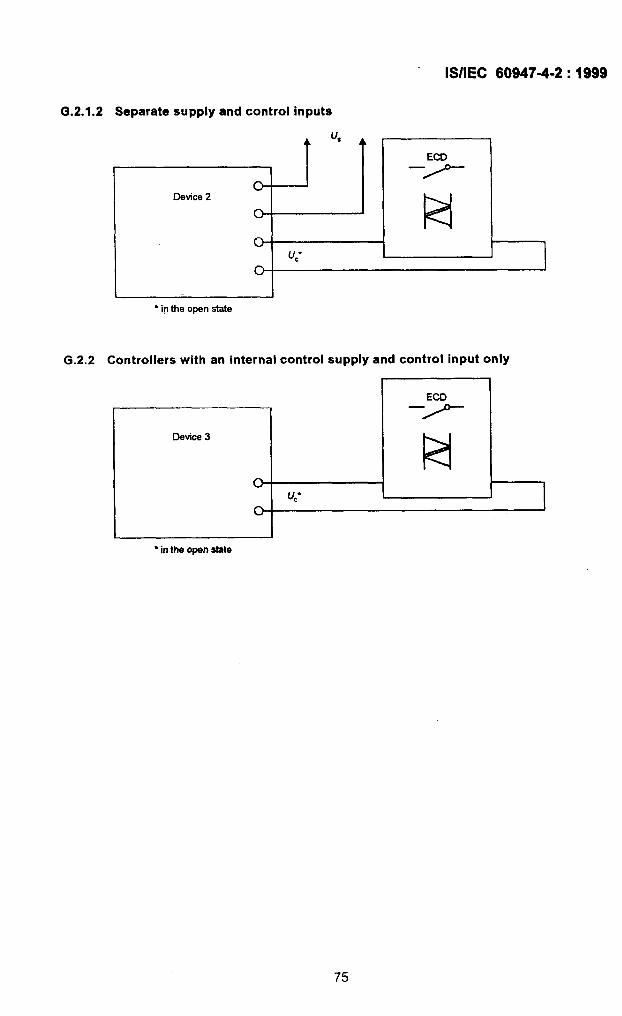
lS/IEC 60947-4-2:1999
G.2.1.2 Separate supply and control inputs
!--G
o-
0-
● ip the open state
u,
u,”
‘7’--
1=4
G.2.2 Controllers with an internal control supply and control input only
Device 3
u,”
● in the openstete
75

lS/lEC 60947-4-2:1999
Annex H(informative)
Items subject to agreement between manufacturer and user
NOTE For the purpose of this annex:
agraement is used in a very wide sense;
user includes testing stations.
Annex J of IEC 60947-1 applies, as far as it is covered by clauses and subclauses of thisstandard, with the following additions:
Clause or 1subclauae number Item
of this standard
i.3.4.6, note Other values of S and/or F (which may be declared by the manufacturer)
5,3.5.3.1 b) Requirements concerning two directions of rotation
5.4 Types of utilization othar than the utilization categories defined in table 2
$,6 Unusual performance features of auxiliary functions or auxiliary circuits
7,1,1, note Equipment to be used at ambient air temperature above 40 “C
7.1,2, note Equipment to be used at altitude higher than 1000 m
3.2.4.1 Verification of the overload capability for controllers with an Xle graatar than 1 000A
5.3.1 EMC requirements:
a) responsibility of the system integrator (user) that systems comply with rulas andregulations applicable at the systems level
b) EMC requirements for very large items of aquipment
8,3.3.1 Immunity: Locations with severa external influences(the manufacturer should be consulted)
S.3,3.3 Verification of immunity in the range of 80 MHz to 1000 MHz
9.3.1, notes 1 and 2 Number of samples for the test sequences (agreemant of tha manufacturer)
Table 13 Results for the verification of blocking and commutating capability:loss of functionality as specified by the manufacturer
9.3.3.6.3 Instructions for fitting the EUT with special featuras to comply with the voltagemeasurement
9.3.5 EMC tests:
a) functional description and definition of specification limits for the acceptancecriteria (to be provided by the manufacturer)
b) condition of minimum conduction (to be choaan by the manufacturer)
9.3.5.2 EMC immunity test: tast of a singla representative sampla (as spacified by themanufacturer)
9.3.5.2.2 Instructions specifying the precautions to ba taken when a specific purposeEMC metallic enclosure is to be opened (to be provided by the manufacturer)
76

lS/lEC 60947-4-2:1999
Annex I(normative)
Modified test circuit for short-circuit testingof semiconductor motor controllers and starters
D
r--. —.—. —-—. —.—. —- —.—. —.—. —.— .—. —.— .
1
II sCPD !
~i I
~ I
! I
! I
I Semkonddu Ij j
!c@dlaf/startw
L .-. —.—.- .—. -.-. —. —.-. —.- .—.-.--— -—-J
KeyD Equipment under test (including connecting cables)
NOTE Outline includes metallic screen or enclosure.
Figure 1.1- Modified circuit for short-circuit testing of semiconductor devices
The standard circuits for short-circuit tests are illustrated in figures 9 to 12 of IEC 60947-1.
This diagram illustrates the modifications to only one phase of the standard test circuit forconducting short-circuit tests of semiconductor controllers. The modifications to each phaseof the test circuit are identical for testing polyphase devices. The only modifications to bemade are those shown in this figure.
77
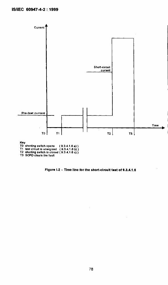
lS/lEC 609474-2:1999
Current
Short-circuitcurrent
Pretest current
TO 11 L T2 T3
KeyTO shorting switch opens (9.3.4.1.6 a))T1 testcircuit is energized (9.3.4 .l.6b))T2 shorting switch isclosed (9.3.4 .l.6c))T3 SCPDclears the fault
Figure i.2 - Time line for the short<ircuit test of 9.3.4.1.6
78

lS/lEC 60947-4-2:1999
Annex J(informative)
Flowchart for constructing bypassed semiconductor controllers tests
Semiconductor switchingdevice
No
.
No
1
Yes
E Unrestricted configurations(8.2.1,8)
Type tests not required (8.2. 1.8)
—
No
No
[
I Market place I
79

.
Bureau of Indian Standards
BIS is a statutory institution established under the Bureau of h?diarr Standards Act, 1986 to promoteharmonious development of the activities of standardization, marking and quality certification of goodsand attending to connected matters in the country.
Copyright
BIS has the copyright of all its publications, No part of these publications may be reproduced in anyform without the prior permission in writing of BIS. This does not preclude the free use, in course ofimplementing the standard, of necessary details, such as symbols and sizes, type or gradedesignations. Enquiries relating to copyright be addressed to the Director (Publications), BIS.
Review of Indian Standards
Amendments are issued to standards as the need arises on the basis of comments. Standards arealso reviewed periodically; a standard along with amendments is reaffirmed when such reviewindicates that no changes are needed; if the review indicates that changes are needed, it is taken upfor revision. Users of Indian Standards should ascertain that they are in possession of the latestamendments or edition by referring to the latest issue of ‘BIS Catalogue’ and ‘Standards: MonthlyAdditions’.
This Indian Standard has been developed from Dot: No. ETD 07 (5634).
Amendments Issued Since Publication
Amendment No. Date of Issue Text Affected
BUREAU OF INDIAN STANDARDSHeadquarters:
Manak Bhavan, 9 Bahadur Shah Zafar Marg, New Delhi 110002Telephones 23230131,23233375, 23239402 Website Www.bis.org. in
Regional Offices: Telephones
Central :
Eastern :
Northern :
Southern :
Western :
Manak Bhavan, 9 Bahadur Shah Zafar Marg
{23237617
NEW DELHI 110002 23233841
1/14, C.I.T. Scheme Vll M, V.I.P. Road, Kankurgachi
{
23378499,23378561KOLKATA 700054 23378626,23379120
SCO 335-336, Sector 34-A, CHANDIGARH 160022
{26038432609285
C.I.T. Campus, IV Cross Road, CHENNAI 600113
{22541216, 2254144222542519,22542315
Manakalaya, E9 MlDC, Marol, Andheri (East) ( 28329295,28327858MUMBAI 400093
. .~ 28327891,28327892
Branches: AHMEDABAD. BANGALORE. BHOPAL. BHUBANESHWAR. COIMBATORE. FARIDABAD.GHAZIABAD. GUWAHATI. HYDERABAD. JAIPUR. KANPUR. LUCKNOW. NAGPUR.PARWANOO. PATNA. PUNE. RAJKOT. TI-IIRUVANANTHAPURAM. VISAKHAPATNAM.
Printed at: AkashdeepPrinters,NewDelhi-2.