is206x - introduction to dsp configuration tool and aec...
TRANSCRIPT

AN2432 IS206X - Introduction to DSP Configuration tool and AEC
Features• Supports Acoustic Echo Cancellation (AEC) to
cancel the acoustic echo coupled into the micro-phone from the loud speaker output.
• Supports Noise Reduction (NR) to suppress the stationary ambient noise to enhance the voice sig-nal quality.
• Supports Equalizer (EQ) to provide the 5-band EQs for both voice and audio applications to com-pensate the imperfect frequency response of the adopted microphone or speaker. Defaulted audio effects are also provided to enhance the user experience.
• Supports High Pass Filter (HPF) to provide a low-latency IIR-structured low-pass filter to filter the unwanted low-frequency band for both MIC and SPK paths.
IntroductionThis application note provides the general information of the IS206X SoC. It also covers noise reduction with high performance and acoustic echo cancellation with advanced signal processing techniques, sophisticated voice and audio enhancement functions, filtering, equalizations and audio effect processing. Additionally for fine tuning the AEC and NR in different applications,during product development. Also, to get guidance on parameters for fine tuning provided in the Digital Signal Processor (DSP) configuration tool in step-by-step format, which allows the system designers to set the DSP features with desired requirements.
The IS206X SoC is designed for high-performance signal processing, which provides excellent voice or audio user experience. The fundamental modules ofthe IS206X SoC are Filter, Stationary NR, SpkGain, MIC Gain, AEC and I2S, and optional modules are AES and Sound effect. These two modules are adjusted based on customers requirement. The AEC function is provided at the microphone (uplink) path in the Synchronous Connection-Oriented (SCO) link connection.
In addition to NR/AEC function, the audio effect functions, multi-band dynamic-range-compression (MB-DRC), virtual bass (VB) enhancement and (A2DP) audio streaming are used in various applications.
For mono speaker/speakerphone and stereo headset applications, the MB-DRC and VB are enabled to have better audio clarity performance. The AW is enabled for better live audio effect for the users.
Tuning Guide
© 2018 Microchip Technology Inc. DS00002432A-Page 1

AN2432
1.0 SIGNAL PROCESSING FLOWBefore introducing the signal processing flow, some abbreviations and terminologies are defined in advance to avoid further confusion. In this document, the path that the Bluetooth® device receives bitstream
and pass to DSP for decoding process, is called as “downlink/downstream/far-end/speaker” path. The path that the Bluetooth device transmits the bitstream, encoded by the DSP processor, is called as “uplink/upstream/near-end/MIC” path.
FIGURE 1: SPEECH SIGNAL PROCESSING
FIGURE 2: AUDIO SIGNAL PROCESSING
Figure 1 and Figure 2 illustrate the block diagram of the DSP processing flow for speaker-phone and headset applications for speech and audio signal processing. The DSP part is focused on speech encoders/decoders and audio decoders along with their corresponding signal processing functions. The embedded analog-to-digital codec (ADC) provides high signal-to-noise ratio (SNR) data conversion with 88 dB and digital-to-analog codec (DAC) provides high SNR data conversion with 98 dB. The Bluetooth and RF/modem processors deal with the medium access control (MAC) and the wireless data transmission. For the speaker and speaker-phone applications, the external audio amplifiers are used to amplify the audio signal.
The speech codecs, Continuous Variable Slope Delta (CVSD) with supported bandwidth of 8 kHz and Modified Subband Coding (mSBC) with supported bandwidth of 16 kHz are available for Bluetooth speech applications, as illustrated in Figure 1. mSBC is the mandatory speech codec defined in Bluetooth Hands-free profile (HFP) 1.6 to provide HD voice quality. As long as the host device establishes the Bluetooth link through HFP 1.6 profile, mSBC is the speech codec regardless of the cellular network conditions, i.e. 3G network or VoLTE.
In Figure 2, DSP includes MB-DRC, VB and AW functions followed by the 5-band EQ for the audio effect. The digital Line-in Loop-back mode allows to pick up the signal from external audio source and feedback into the DSP for audio processing, which
DS00002432A-Page 2 © 2018 Microchip Technology Inc.

AN2432
goes through the audio effect and 5-band EQ functions, as the Bluetooth A2DP audio streaming. The Flash variants of IS206x family support both SBC and AAC-LC decoder. The ROM variants do not support AAC-LC. For specific details, refer to “IS2062/64 Bluetooth 4.2 Stereo Audio SoC Datasheet (DS60001409)”. However, for legal use of AAC-LC decoder, the license from “Via Licensing” is necessary before the product is launched to the market.© 2018 Microchip Technology Inc. DS00002432A-Page 3

AN2432
2.0 DSP CONFIGURATION TOOLFigure 3 shows the DSP configuration tool window with various tabs: Main Function, Voice Function, Audio Function, and I2S/PCM.
This section of the Application Note provides thefunctionalities of the Main Function tab. It also covers two configurable modes, “Speakerphone” mode and “Speaker” mode, which are used for overall DSP settings.
The “Speakerphone” mode allows the user to configure the NR/EC/EQ/FIR functions, while “Speaker” mode is not permitted to configure. The user need to select either of these modes, clicking DSP Default button initializes the parameters back to their default settings.
• Load button — It can be used to load and pass the information of the DSP-related parameters in the EEPROM file and display its corresponding values automatically in other tabs.
• Save button — It can be used to save the current settings in the Graphic User Interface (GUI) tool and transform them to the EEPROM format. For information on EEPROM format, refer to 7.0“EEPROM File Format”.
• DSP Parameter — Used to export the NR/AEC/Sound effect/DSP system control parameters, but not the DSP patch code, I2S coefficients, and EQ coefficients.
In the Main Function tab, the user need to select the required IC number and then configure its corresponding DSP behavior.
Note: In the DSP configuration tool, the product portfolio for mono-headset (MHS), stereo-headset (SHS), mono speakerphone (1SPK), stereo speakephone (2SPK) and I2S interface applications are supported.
FIGURE 3: DSP CONFIGURATION TOOL
DS00002432A-Page 4 © 2018 Microchip Technology Inc.

AN2432
3.0 VOICE PROCESSING FUNCTIONS
The Voice processing functions are used to suppress ambient noise, echo and other call interferences during voice calls using the following features to increase the quality of voice.
• High-pass filter for SPK/ MIC paths (HPF) — Remove low-frequency board/background noise
• Noise Reduction (NR)• Echo Cancellation (EC)/ Suppression (ES) — Lin-
ear/ non-linear echo cancellations• Comfort noise insertion for MIC paths — Insert
comfort noise to maintain stable noise level• 5-band EQs for SPK/MIC paths — Compensate
frequency imperfection• MIC and Speaker Gain Controller
3.1 High-Pass Filter The high-pass filter (HRF) provides an option for a low latency and infinite impulse response (IIR) filtering.
The main function of the HPF contains seven selectable cutoff frequencies used to filter the unwanted low-frequency signals, such as PCB noise, coupled current noise, and wind noise etc. It is a trade-off between the speech signal quality and the noise reduction level. The default cutoff frequencies for the speaker is 300 Hz and MIC is 210 Hz.
Figure 4 illustrates the interface of HPF parameters for both speaker and microphone paths in the DSP tool.
FIGURE 4: CONFIGURATION OF HIGH-PASS FILTER PARAMETER IN DSP TOOL
© 2018 Microchip Technology Inc. DS00002432A-Page 5

AN2432
3.1.1 EEPROM SETTINGSTo enable the far-end HPF module, see Table 3-1. TABLE 3-1: EEPROM ADDRESSES FORENABLING HPF AT THE SCO SPEAKER PATH
Address Value
Bit 5 at 0x0300 0x1
To enable the near-end HPF module, see Table 3-2TABLE 3-2: EEPROM ADDRESSES FOR
ENABLING HPF AT THE SCO MIC PATH
Address Value
Bit 4 at 0x0300 0x1
.
The EEPROM addresses and settings for HPF are provided in Table 3-3.
TABLE 3-3: EEPROM ADDRESSES FOR CONFIGURING HPF FUNCTIONFunctionality EEPROM address Default Settings
Near-end HPF 0x0316 0x02 0x00: 50 Hz0x01: 80 Hz
0x02: 120 Hz0x03: 180 Hz0x04: 210 Hz0x05: 300 Hz0x06: 400 Hz
Far-end HPF 0x0317 0x02
3.2 Noise ReductionThe noise reduction (NR) function suppresses the stationary noises present in the far-end/downstream and near-end/upstream signals. The NR module can also effectively suppress the unwanted noise with the proprietary intelligent voice activity detection (VAD), while maintaining satisfactory quality for the voice communications. This function allows both near-end and far-end users to experience the benefits.
Figure 5 illustrates the interface of the NR and Dual Mic NR parameters in the DSP tool.
DS00002432A-Page 6 © 2018 Microchip Technology Inc.
AN2432
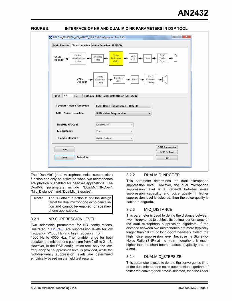
FIGURE 5: INTERFACE OF NR AND DUAL MIC NR PARAMETERS IN DSP TOOLThe “DualMic” (dual microphone noise suppression) function can only be activated when two microphones are physically enabled for headset applications. The DualMic parameters include “DualMic_NRCoef”, “Mic_Distance”, and “DualMic_Stepsize”.
Note: The “DualMic” function is not the design target for dual microphone echo cancella-tion and cannot be enabled for speaker-phone applications.
3.2.1 NR SUPPRESSION LEVELTwo selectable parameters for NR configurations, illustrated in Figure 5, are suppression levels for low frequency (<1000 Hz) and high frequency (from 1000 Hz to 4000 Hz). The tunable range for both speaker and microphone paths are from 0 dB to 21 dB. However, in the DSP configuration tool, only the low-frequency NR suppression level is provided, while the high-frequency suppression levels are determined empirically based on the field test results.
3.2.2 DUALMIC_NRCOEF:This parameter determines the dual microphone suppression level. However, the dual microphone suppression level is a trade-off between noise suppression capability and voice quality. If higher suppression level is selected, then the voice quality is easier to degrade.
3.2.3 MIC_DISTANCE:This parameter is used to define the distance between two microphones to achieve its optimal performance of the dual microphone suppression algorithm. If the distance between two microphones are more (typically longer than 10 cm or long-boom headset). Select the high noise suppression level, because its Signal-to-Noise Ratio (SNR) at the main microphone is much higher than the short-boom headsets (typically around 4 cm).
3.2.4 DUALMIC_STEPSIZE:This parameter is used to denote the convergence time of the dual microphone noise suppression algorithm. If faster the convergence time is selected, then the linear
© 2018 Microchip Technology Inc. DS00002432A-Page 7

AN2432
noise suppression capability is not better than the slowest convergence time. This is a trade-off between faster convergence time and better noise suppression.3.2.5 EEPROM SETTINGSTo enable the far-end NR module, refer Table 3-4.
TABLE 3-4: EEPROM ADDRESSES FOR ENABLING NR AT THE SCO SPEAKER PATH
Address Value
Bit 2 at 0x01df 1Bit 0 at 0x01ec 1
Bit 0-3 at 0x01E1 0x1
To enable the near-end NR module, refer Table 3-5.TABLE 3-5: EEPROM ADDRESSES FOR
ENABLING NR AT THE SCO MIC PATH
Address Value
Bit 1 at 0x01df 1Bit 0 at 0x01ec 1
Bit 4-7 at 0x01E1 0x1
Table 3-6 provides the EEPROM addresses to modify the NR noise suppression levels.
TABLE 3-6: EEPROM ADDRESSES FOR CONFIGURING NR FUNCTIONFunctionality EEPROM address Default Settings
Far-end NR 0x0325 0x16 0x7F: 0 dB suppression0x40: 6 dB suppression0x2D: 9 dB suppression0x20: 12 dB suppression0x16: 15 dB suppression0x10: 18 dB suppression0x0B: 21 dB suppression0x08: 24 dB suppression0x06: 27 dB suppression0x04: 30 dB suppression
Near-end NR 0x0327 0x10
3.3 Echo CancellationTo linearly cancel and suppress, the returned echo, both acoustic echo canceller (AEC) and acoustic echo suppression (AES) functions are required. The difference between AEC and AES is AEC can cancel the linearly coupled echo by maintaining the desired near-end speech. With the better AEC performance, the full-duplex speech communication is achieved easily. But nonlinear echo generated by speakerphone housing, imperfect speaker/microphone devices and undesired echo environment are not canceled by AEC. Hence, the function of AES is to suppress input signal mixed with desired signal and unwanted echo signal in the frequency domain based on the information of voice activity detection. Therefore, select the
parameters for AES and Double-Talk Threshold carefully to prevent from the degradation of desired speech quality in the case of strong nonlinear echo, or close placement between the microphone and speakers. Figure 6 illustrates the AEC tuning interface in the DSP configuration tool.
DS00002432A-Page 8 © 2018 Microchip Technology Inc.

AN2432
FIGURE 6: AEC TUNING INTERFACE IN THE DSP CONFIGURATION TOOLThe adjustable parameters to fine tune the performance of echo cancellation are provided as follows:
3.3.1 AEC_STEPSIZEThe AEC convergence speed. If fast convergence rate is selected, then lower echo cancels out linearly. On the other side, better linear echo cancellation is achieved.
3.3.2 AEC TAP LENGTH The tap length must be selected in which the tap length must be longer than the echo tail and also it is the trade-off between echo cancellation (EC) performance and mega-instructions per second (MIPS). If longer the tap length, then higher the MIPS and DSP power consumption.
3.3.3 DOUBLE-TALK THRESHOLDThe full-duplexity of the AEC means the level of how much is the far-end user can listen to the near-end user voice, while both users speak simultaneously.Basically, this parameter maps to a threshold that controls the AES to suppress the echo nonlinearly. If
this parameter is configured to be more favorable for half-duplexity, the double-talk capability gets degrade more, but removes more residual echo.
If we assume that x[n] is near-end signal and y[n] is far-end signal, then the cross-correlation equation between these signals are indicated as follows:
Echo_corr = EMA (corr_coef), where EMA is exponentially moving average.
corr_coef =
Σx n[ ]y n[ ] Σx n[ ]2 Σy n[ ]2( )÷
© 2018 Microchip Technology Inc. DS00002432A-Page 9

AN2432
FIGURE 7: DOUBLE-TALK THRESHOLD PARAMETERIf the Double-Talk Threshold is selected as 0x50, the threshold to determine the presence of echo is also high. As a result, the AES function is less likely to get enabled to suppress residual echo, see Figure 7.
On the other hand, if the Double-Talk Threshold is selected as 0x2D, this setting is more active to enable AES function for echo suppression.
3.3.4 AES_SUPPRESSIONThis parameter determines the maximum nonlinear echo suppression capability.
3.3.5 LINEAR AEC THRESHOLDThis parameter determines the linearity threshold of the returned echo. If “Worst linearity” option is selected, then the AES function is configured to easily enableand suppress the residual echo. The “Higher linearity”
option allows having better Full-duplex echo cancellation performance with more echo in the returned signal.
3.3.6 EEPROM SETTINGSTo enable the AEC, users need to set the addresses as given in Table 3-7.TABLE 3-7: EEPROM ADDRESSES FOR
ENABLING AEC FUNCTIONAddress Value
Bit 0 at 0x01df 1Bit 4 at 0x01ec 1
Bit 0 to 2 at 0x01E2 0x1
The AEC parameters and their corresponding address are provided in Table 3-8.
TABLE 3-8: CONFIGURING THE AEC PARAMETERSParameters Address Description Default Value
AEC_Stepsize 0x032DBit 4 to 7
0x01: Fastest AECconvergence to
0x06: Slowest AECconvergence
0x03
AECTapLength 0x0311 0x01: 8 msec Echo Tail to 0x0A: 80 msec Echo Tail
0x06
Double-TalkThreshold
0x0322/0x0339 (mSBC) 0x7F: More Full Duplex to0x1C: Least Full Duplex
0x50
AES_Suppression 0x0313/0x0336 (mSBC) 0x01: Less Echo Suppressionto 0x10: Most Echo Suppres-
sion
0x04
Linear AEC Threshold 0x032E/0x0338 (mSBC)Bit 0 to 3
0x7F: Worst Linearityto 0x03: Best Linearity
0x07F
DS00002432A-Page 10 © 2018 Microchip Technology Inc.

AN2432
3.4 Digital MIC GainThe digital MIC gain provides different digital control functions at the microphone path and allows the user to boost the volume digitally. If the analog amplifier of ADC is unable to provide enough gain, then the digital boost part of the dynamic MIC control is placed at the end of all digital signal processing modules, as illustrated in Figure 8.The suppressed echo can be amplified by adjusting the digital MIC gain.
Note: The available selections of the dynamic range gets automatically updated accord-ing to the MIC gain (codec) by the DSP configuration tool.
Figure 8 illustrates the parameters to adjust the configuration of the digital MIC gain and comfort noise.
3.4.1 EEPROM SETTINGS:To enable the Digital MIC gain, configure the following addresses as given in Table 3-9.
TABLE 3-9: EEPROM ADDRESSES FOR ENABLING DIGITAL BOOST GAIN AT SCO MIC PATH
EEPROM address MIC Gain (Digital)
MIC Gain (Digital) 0x00: -19 dB Digital Boost0x03: -16 dB Digital Boost0x05: -14 dB Digital Boost0x07: -12 dB Digital Boost
.
.
.0x13: 0 dB Digital Boost0x15: 2 dB Digital Boost
.
.
.0x27: 20 dB Digital Boost
FIGURE 8: PARAMETERS FOR MIC GAIN AND COMFORT NOISE
© 2018 Microchip Technology Inc. DS00002432A-Page 11

AN2432
3.5 Comfort NoiseThe comfort noise is generated by a random number generator, and its frequency response is constant across all frequencies. The main purpose is to provide a constant noise level to prevent the speech codec algorithm of host cellphones from injecting unwanted noise, which degrades speech clarity at the far-end listener side.Background Noise: This adjusts the level of the comfort noise.
3.5.1 EEPROM SETTINGSTo enable the comfort noise at SCO MIC path, configure the EEPROM addresses as given in Table 3-10.TABLE 3-10: EEPROM ADDRESSES FOR
ENABLING THE COMFORT NOISE AT THE SCO MIC PATH
EEPROM address MIC Gain (Digital) values
0x306(MSB)/0x307(LSB)
0x7FFF: 0 dBc Highest Comfort Noise level0x4000: 6 dBc Comfort Noise level0x2000: 12 dBc Comfort Noise level0x1000: 18 dBc Comfort Noise level0x0800: 24 dBc Comfort Noise level0x0400: 30 dBc Comfort Noise level0x0200: 36 dBc Comfort Noise level0x0100: 42 dBc Comfort Noise level0x0080: 48 dBc Comfort Noise level0x0040: 54 dBc Comfort Noise level0x0020: 60 dBc Comfort Noise level0x0010: 66 dBc Comfort Noise level0x0008: 72 dBc Comfort Noise level0x0004: 78 dBc Comfort Noise level(Recommended)0x00002: 84 dBc Comfort Noise level0x00001: No Comfort Noise level
To support HFP 1.6, configure the EQ coefficients separately for 8 kHz and 16 kHz, the user need to click the Custom EQ – MIC or Custom EQ – SPK button to display EQ configuration window, as illustrated in Figure 9.
3.6 EqualizerThe Equalizer (EQ) provides the flexibility for compensating the imperfect frequency responses of the selected microphone and speaker. This function provides a 5-band customized filter for both MIC and speaker paths.
Figure 9 illustrates the interface to configure equalizers for both speaker and microphone paths using buttons.
• Custom EQ – MIC (for Microphone path) • Custom EQ – SPK (for Speaker path)
Note: The Custom EQs with mSBC is config-ured for the Hands-free profile (HFP) 1.6 supporting the wideband (16 kHz sam-pling rate) speech features.
DS00002432A-Page 12 © 2018 Microchip Technology Inc.

AN2432
FIGURE 9: EQ CONFIGURATION INTERFACE FOR SPEAKER AND MIC PATHS IN SCO ORSPEECH MODE
Figure 10 illustrates how to configure the Equalizer functions.
FIGURE 10: CONFIGURING THE EQUALIZER FUNCTIONS
© 2018 Microchip Technology Inc. DS00002432A-Page 13

AN2432
The required frequencies and gain/attenuations to be entered in the columns. The columns of Quality factor (Q) are to configure the cutoff frequencies of each equalizer band. Consider the value of “Q” is smaller, then wider the bandpass cutoff frequency, as illustrated in Figure 10. The “M+” and “MR” buttons function as the calculator's “M+” and “MR”. The purpose of these two buttons are to record the frequency responses for easy analysis comparison.The user need to click the Save button to save the frequency response that is designed and the system automatically stores the current EQ's configuration into
a file. The user need to click the Load Response button to restore the frequency response and EQ configurations that was designed previously.
The section “Stage” configures the number of bands of 1-order IIR filter used. The fewer the “Stages”, then lower the MIPS and power consumption.
3.6.1 EEPROM SETTINGS:To enable the EQ for voice applications, configure the bits given in Table 3-11.
TABLE 3-11: EEPROM ADDRESSES FOR ENABLING THE EQ FUNCTIONSBit Address MIC path Speaker path
Bit 3 of 0x1EC 1 1Bit 6 of 0x1DF 1 Not requiredBit 5 of 0x1DF Not required 1
0x356/0x358 (mSBC) 0x0B/0x0D Not required0x357/0x359 (mSBC) Not required 0x0C/0x0E
Bit 2 of 0x1E1 1 Not requiredBit 6 of 0x1E1 Not required 1
Figure 11 illustrates the functions of the Q factor.
FIGURE 11: Q FACTOR FUNCTION
DS00002432A-Page 14 © 2018 Microchip Technology Inc.

AN2432
3.7 Speaker/MIC Gain SettingsThe speaker gain levels and MIC gain levels are configured in the DSP configuration tool. There are three different number of speaker gain levels, which are selectable based on particular requirements. Once the number of the speaker gain level is determined, ensure to choose the corresponding gain for each level.The gain difference between each MIC gain level for “MIC Gain (codec)” is ranging between 2.7 dB to 3.4 dB per step, as illustrated in Figure 12.
3.7.1 EEPROM SETTINGS:To enable the microphone and speaker gains, configure the bits given in Table 3-12.TABLE 3-12: EEPROM ADDRESSES FOR
MIC AND SPEAKER GAINSFeature EEPROM Address
MIC path 0x00C5Speaker path 0x018D to 0x019C
FIGURE 12: INTERFACE FOR THE SPEAKER GAIN CONFIGURATION IN THE SCO MODE
© 2018 Microchip Technology Inc. DS00002432A-Page 15

AN2432
Figure 13 illustrates the MIC gain configuration in the SCO mode.FIGURE 13: MIC GAIN CONFIGURATION IN THE SCO MODE
DS00002432A-Page 16 © 2018 Microchip Technology Inc.

AN2432
4.0 AUDIO PROCESSING FUNCTIONS
The Audio processing is used to enhance the audio listening experience for the following functionalities:
• 5-band EQ for SPK• Multi-band dynamic range compression (MB-
DRC)• Virtual bass (VB) enhancement — Enhance the
bass using psychoacoustic algorithm• Audio widening (AW) process — Make speakers
placed close apart sound like being placed far apart from each other
Figure 2 illustrates the system diagram of the audio signal processing. In addition to the SBC decoder, only one EQ is allowed to process the audio signal. Figure 14 illustrates the configuration of the EQ for the audio function. In the column “EQ Mask Selection”, select the adjustable special audio sound effect. Except the option “Custom EQ”, use an external button
to select different sound effects. The procedure to configure “Custom EQ 2” is identical to the EQ, refer to 3.6“Equalizer” section for details.
4.0.1 EEPROM SETTINGS:To enable the EQ for audio applications, configure the bits given in Table 4-1.TABLE 4-1: EEPROM ADDRESSES FOR
ENABLING THE EQ IN THE AUDIO (OR SBC) MODE
Address Values
Bit 3 of 0x1EC 1Bit 5 of 0x1E0 1
0x1E7 0x0A0x1E8 0x070x1E9 0xFF
FIGURE 14: EQ CONFIGURATION INTERFACE FOR AUDIO MODE
© 2018 Microchip Technology Inc. DS00002432A-Page 17

AN2432
4.1 Speaker Gain Setting / Line-inGainSimilar to the speaker setting for voice applications, the number of speaker gain level is also selectable. For selection procedure, refer to 3.7“Speaker/MIC Gain Settings”.
FIGURE 15: CONFIGURATION INTERFACE FOR SPEAKER GAINS IN THE AUDIO MODE
4.2 Auto Power-off mode for Line-in Silence detection
The DSP function enables the system to detect power level of the Line-in signal.The power level of the Line-in signal is calculated digitally and the silence status is reported to the Bluetooth MAC controller. The “Initial Line-In SPK Gain” is to configure the Line-in gain to amplify the external signal source and playback to the speakers.
The “Silence Detection Threshold” determines the silence power threshold level of Line-in signal for auto power-off mechanism.
DS00002432A-Page 18 © 2018 Microchip Technology Inc.

AN2432
FIGURE 16: LINE-IN (AUX-IN) CONFIGURATION INTERFACE4.2.1 PARAMETERS OF LINE-IN SILENCE DETECTION:
Figure 16 illustrates the parameters of Line-in silence detection.
4.2.2 SILENCE DETECTION THRESHOLDThis parameter determines the silence power threshold level of Line-in signal for auto power-off mechanism.
4.2.3 INITIAL LINE-IN SPEAKER GAINFirmware initializes with this DAC gain, while playing Line-in mode with selected index “0x0A”. The Gain (DB) values for the indexes are mapped to a table extracted from Figure 17. This will increase/decrease the speaker volume.
4.2.4 LINE-IN MAX LEVELFirmware uses this level index to constrain maximum DAC gain in Line-in mode with selected index “F”. The Gain (DB) values for the indexes are mapped to a table extracted from Figure 17.
4.2.5 LINE-IN MIN LEVELFirmware uses this level index to constrain minimum DAC gain in Line-in mode with selected index “0”. The Gain (DB) values for the indexes are mapped to a table extracted from Figure 17.
Note: The Parameters “Line-in max and Line-in min levels” hold the speaker gain value with in the minimum and maximum ranges.
4.2.6 LINE-IN ADC GAINFirmware configures the ADC gain, while playing Line-in mode with selected index “3dB, 0x09”. This controls the volume in Microphone.
When the Line-in mode is connected and there is no audio (the RMS power of noise) below the threshold set in the DSP tool, the DSP sends a signal to 8051. Then 8051 sends power down signal for the system. If there is an audio after the power-off, it cannot play as the system is off and it requires a power-on.
For details, refer to the “BM64S-114 Evaluation Board User's Guide (DS00000000)”.
© 2018 Microchip Technology Inc. DS00002432A-Page 19

AN2432
FIGURE 17: CONFIGURATION INTERFACE FOR SPEAKER GAINThe time settings for the system power-off occurs in the MCU firmware UI tool, as illustrated in Figure 18.
FIGURE 18: AUTO POWER-OFF
FIGURE 19: AUTO POWER-OFF HELP
DS00002432A-Page 20 © 2018 Microchip Technology Inc.

AN2432
4.3 Sound effect – Audio Wideningand Multiband Dynamic Range Compression
The Audio Widening (AW) and Multiband Dynamic Range Compression (MB-DRC) are the two functionalities with embedded audio signal processing, which provides better audio quality and user experience without using the external digital signal processor in the IS20XX SoC family.
The AW function processes the audio signal by manipulating the signal played by the closely placed speakers, which sounds like the speakers placed far. In such way, the sound quality can be increased with better surrounding effects.
The MB-DRC function is an automatic volume control and uses the following compression mechanisms. Downward compression reduces the louder sounds over a certain threshold, while quiet sounds remain
unaffected. Upward compression increases the loudness of sounds below a certain threshold by leaving the louder sounds unaffected.
Both downward and upward compression reduces the range of an audio signal. This is done for aesthetic reasons to deal with the technical limitations of audio equipment, or to improve audibility of audio in noisy environments. In this way, it reduces the dynamic range of an audio signal. This may be done for aesthetic reasons to deal with technical limitations of audio equipment, or to improve audibility of audio in noisy environments.
4.3.1 PARAMETERS OF AW AND MB-DRC:
Figure 20 illustrates the adjustable parameters for AW and MB-DRC. The check boxes for MB-DRC and AW must be checked to enable these functions.
FIGURE 20: USER INTERFACE FOR SOUND EFFECT CONFIGURATIONS
© 2018 Microchip Technology Inc. DS00002432A-Page 21

AN2432
4.3.2 AUDIO EFFECT – MASKSELECTIONThe “Audio Effect - Mask Selection” is to select the combinations of audio effects, that can be selected by either of the external buttons, as highlighted in Figure 20. Also, select All off, MB-DRC On and All On. When the “Next” button is selected, the audio effect switches from one to its next. The order of selected audio effect is All off, MB-DRC On, All On and All Off.
4.3.3 DEFAULT AUDIO EFFECTThis parameter is to select the initial Audio Effect mode, after the device is power-on.
4.3.4 MB-DRC PARAMETERSThe general concept of MB-DRC is to transform the input signal nonlinearly to its output. The parameters to control the behavior of MB-DRC are “Knee Th”, “Compression Ratio”, “Make-Up Gain”, “Attack Time”, “Release Time” and “Bass Enhancement”. The MB-DRC provides adjustable parameters in three different bands (0 kHz to 1 kHz, 1 kHz to 6 kHz and >6 kHz) to process the input signal in a better way. The description of these parameters are listed as follows:
4.3.5 KNEE THThis parameter corresponds to the compression threshold, as illustrated in Figure 20. This parameter constrains the sound level to which the make-up gain is applied.
4.3.6 COMPRESSION RATIOThe term Compression Ratio (CR) compresses the input sound level, exceeding the “Knee Th” of audio signal. However, if CR is closer to 0, the distortion due to the compression will be generated more easily.
4.3.7 MAKE-UP GAINMake-up gain is the maximum gain applying to audio signal, in which the average power is between silence threshold and the compression knee. This parameter boosts, the soft music signal to an audible level,especially in a noisy environment.
4.3.8 ATTACK TIME AND RELEASE TIMEThe Attack time and Release time parameters are the period of time, which reaches 1-1/e = 63% of its final value. The difference between attack and release time constants, are illustrated in Figure 21. The attack time is the time period to decrease the signal amplitude exceeding the level of “Knee Th”, while the release time is the time period to increase the signal amplitude below the level of “Knee Th” to its desired “Make-Up Gain” level.
FIGURE 21: ATTACK AND RELEASE TIME PARAMETERS
4.3.9 BASS ENHANCEMENT:This parameter controls the level of bass enhancement, which is enabled along with the MB-DRC function.
Figure 22 illustrates the mapping function of MB-DRC.
DS00002432A-Page 22 © 2018 Microchip Technology Inc.

AN2432
FIGURE 22: MAPPING FUNCTION OF MB-DRC4.3.10 AUDIO WIDENING PARAMETERS:The Audio Widening (AW) sound effect is to process the music signal played by the speakers, which are placed close, apart, or inside one housing to make it sound like being placed far apart from each other, as illustrated in Figure 23. The virtually generated widening signals are mixed with original signals with various levels of weighting pairs, as illustrated in Figure 24.
FIGURE 23: AUDIO WIDENING EFFECT
© 2018 Microchip Technology Inc. DS00002432A-Page 23

AN2432
4.3.11 AUDIO WIDENING LEVEL:This parameter controls the extent of AW effect. Basically, it is a mixing ratio of original sound and AW-processed sound signal. Figure 24 illustrates the block diagram of AW generator.FIGURE 24: BLOCK DIAGRAM OF AW GENERATOR
Table 4-2 provides the parameters of AW effect.
TABLE 4-2: PARAMETERS OF AW EFFECTEEPROM address Values
0x353 Bit 7 to 4: Side CoefBit 3 to 0: Main Coef
0x00: Side Coef = 0; Main Coef = 10x01: Side Coef = 1/16; Main Coef = 10x02: Side Coef = 2/16; Main Coef = 10x03: Side Coef = 3/16; Main Coef = 14/160x04: Side Coef = 4/16; Main Coef = 14/160x05: Side Coef = 5/16; Main Coef = 14/160x06: Side Coef = 6/16; Main Coef = 13/160x07: Side Coef = 7/16; Main Coef = 13/160x08: Side Coef = 8/16; Main Coef = 13/160x09: Side Coef = 9/16; Main Coef = 12/160x0A: Side Coef = 10/16; Main Coef = 12/160x0B: Side Coef = 11/16; Main Coef = 12/160x0C: Side Coef = 12/16; Main Coef = 11/160x0D: Side Coef = 13/16; Main Coef = 11/160x0E: Side Coef = 14/16; Main Coef = 10/160x0F: Side Coef = 15/16; Main Coef = 9/16
DS00002432A-Page 24 © 2018 Microchip Technology Inc.

AN2432
5.0 I2S DIGITAL OUTPUT/INPUT INTERFACE
FIGURE 25: I2S PARAMETER TUNING INTERFACE FOR IS2023 SOC
The IS2063/64 SoC or BM63/64 Bluetooth module supports the I2S interface for digital input/output. In this document, the hardware wiring issue is discussed, but only the FW configuration is introduced. The selectable parameters are “I2S Mode”, “Data Bitwidth”, “MIC ADC Selection” and “RFS Setting”, as illustrated in Figure 25.
The details of these parameters are discussed in the subsequent sections.
5.1 I2S ModeThis parameter contains two modes:
• Master mode - The IS2063/64 SoC serves as a master to provide clock and frame synchronous signals for the master/slave data synchroniza-tions, as illustrated in Figure 27.
• Slave mode - The IS2063/64 SoC serves as a slave to receive clock and frame synchronous sig-nals from the external codec or DSP devices, as illustrated in Figure 28.
5.2 Data Bitwidth:The numbers of bits for DR/DT are expected to receive from external codec or DSPs, or transmit to external codec or DSPs, as illustrated in Figure 26.
• 16 bits: The Bluetooth supported codec can only have 16-bit resolution.
• 24 bits: The trailing zeros in LSBs is the only way to meet the external DSP, that supports 24-bit I2S port requirement. In this way, the 16 bits are filled in 16 MSBs and 8 zeros in LSBs.
© 2018 Microchip Technology Inc. DS00002432A-Page 25

AN2432
FIGURE 26: I2S CONFIGURATIONS FOR 16-BIT/24-BIT5.3 MIC ADC Selection:If the hands-free function is supported, select the following ADC configuration:
• Internal ADC: On-chip ADC is used• External ADC: External ADC/DSP is selected
FIGURE 27: I2S HARDWARE CONFIGURATIONS FOR MASTER MODE
DS00002432A-Page 26 © 2018 Microchip Technology Inc.

AN2432
FIGURE 28: I2S HARDWARE CONFIGURATIONS FOR SLAVE MODES WITH EXTERNAL ADC5.4 RFS Setting:This setting determines either the high or low level of RFS signal that represents L channel data for both left channel and right channel.
• RFS low-level (Left channel): Refer to timing dia-gram, as illustrated in Figure 29
• RFS high-level (Right channel): Refer to timing diagram, as illustrated in Figure 30
FIGURE 29: LOW AND HIGH LEVELS OF RFS DENOTE IN LEFT CHANNEL
FIGURE 30: LOW AND HIGH LEVELS OF RFS DENOTE IN RIGHT CHANNEL
© 2018 Microchip Technology Inc. DS00002432A-Page 27

AN2432
6.0 GUIDELINES FOR TUNING ECHO CANCELLATION PERFORMANCE
This section introduces a guideline to fine tune the echo cancellation performance. There are usually three requirements for the EC tuning. They are high MIC volume, echo-free and double-talk (DT)
performance. These three requirements are different with each other. For example, if the high volume at MIC path is required, the echo will also gets amplified. Therefore, tuning of the parameters is required to make echo inaudible, which results in poor DT performance. Figure 31 illustrates the first five steps basically handling the whole speaker phone/car kit echo issues.
FIGURE 31: ILLUSTRATION OF THE AEC TUNING FLOW
6.1 Step 1Download all the merged patch code, which consists of the settings for user interface (UI) 8051 and DSP, and merged patch code for 8051 and DSP parts. Some DSP functions are implemented in the patch code to download the latest patch code that gets synchronize with this document.
6.2 Step 2Before tuning the AEC performance, the maximum desired speaker output level must be determined, that is, the recommended speaker output volume must be atleast 95 dB sound pressure level (SPL) for indoor speakerphones and 100 dB SPL for car-kit applications.
Note: The target speaker output volume must be determined at the beginning based on the required specification.
6.3 Step 3This is the principle step to adjust the MIC gain to a suitable value. It is not necessary to set the MIC to its maximum level because of the slope over load effect, as illustrated in Figure 32, which is caused by the CVSD codec that naturally suppress the high frequency parts and make it works as a low-pass filter. This effect distorts the near-end speech and make it not as clear as the softer MIC gain levels.
For more information on the CVSD slope over load effect, refer to the “Continuously Variable Slope Delta Modulation: A Tutorial” document available for download at http://www.datasheetcatalog.org/datasheet/CML/mXxyzvw.pdf.
DS00002432A-Page 28 © 2018 Microchip Technology Inc.

AN2432
FIGURE 32: CVSD SLOPE OVERLOAD EFFECT6.4 Step 4This is an optional step. The purpose of this step is to shape the frequency response of the speaker output by lowering the low frequency (<1 kHz) and enhancing the high frequency parts (1 kHz to 3 kHz).
The echo reverberation within the speaker phone/car kit housing is reduced in this way, so that the linearity of the echo coupled to the MIC input can be better. The echo linearity is highly associated with the AEC performance. Figure 33 illustrates an example of these settings which are obtained empirically. However, the required frequency gets changed in terms of which speaker and housing are selected.
FIGURE 33: EXAMPLE OF THE FREQUENCY SHAPING FOR SIGNAL AT SPEAKER PATH
© 2018 Microchip Technology Inc. DS00002432A-Page 29

AN2432
6.5 Step 5The purpose of this step is to fine tune the AEC performance. Basically it is divided into two parts: Single-Talk echo tuning and Double-Talk echo tuning.6.5.1 SINGLE-TALK ECHO TUNINGThe parameters “Double-Talk Threshold” and “AES Suppression” (refer to 3.3“Echo Cancellation”) are responsible for tuning the Single-Talk echo performance. As per thumb rule, first adjust the parameter of “Double-Talk Threshold” from “0x7F” to “0x1C”. If the value of the “AES Suppression” is “0x04” and still not able to suppress the echo (audible single-talk echo) effectively, then start to fine tune the “AES Suppression” from “0x01” to “0x0F”.
Note: Although the selectable value of “Double-Talk Threshold” is up to 0x1C, these two values are not recommended to suppress the echo, since it would distort the MIC speech severely.
6.5.2 DOUBLE-TALK ECHOIf the Single-Talk echo is able to get suppressed effectively by the default settings of “Double-Talk Threshold” and “AES Suppression”, then the double-talk performance can be increased further and fine tuned. The first recommended parameter for the double-talk performance is “AES Suppression”, which is suggested to tune from “0x0F” to “0x01” (No half-duplex). If the single-talk echo is still not present for “Double-Talk Threshold” at “0x01”, the parameter “AES Suppression” is then considered to be adjusted from “0x0C” to “0x01”.
The possible measures to improve the double-talk performance are as follows:
1. Increase the AEC MIC gain: To increase the MIC gain, refer to 6.3“Step 3”, as both AES and AEC suppresses echo as the double-talk near-end speech. The double-talk performance can be improved, if the near-end speech energy is raised up, so that the near-end speech can become audible, while no single-talk echo is present.
2. Adjust the frequency shaping, as illustrated in Figure 33: If the speaker output level is very loud and echo-to-speech ratio at the microphone input is too high, then the way to improve this is to further suppress the low-frequency part of the speaker output. As a result, the echo-to-speech ration at the low frequency parts of the micro-phone input is further reduced and can have the better double-talk performance.
3. Use the handsets to support the full-duplex AEC: Some handsets, such as “Samsung Gal-axy II” and “HTC Incredible” etc, don’t support the full-duplex speech communication, while
connecting with the Bluetooth hand free devices. In this way, satisfactory full-duplex per-formance is not obtained, while using these handsets.
4. Allow only one channel output (assuming for the stereo speakerphone case): If the distance between the microphone and one of the speaker channels are very close (< 4 cm), the AEC tun-ing for the full-duplexity becomes very difficult. One simple way is to turn-off the closer speaker channel output and only allow the other speaker to output, so that the full-duplexity can be much easier to achieve. The User Interface (UI) con-figures the number of the desired speaker chan-nel outputs.
DS00002432A-Page 30 © 2018 Microchip Technology Inc.

AN2432
7.0 EEPROM FILE FORMATThe DSP configuration tool is to generate the EEPROM formatted file, as illustrated in Figure 34, which is based on the configurable parameters on the GUI.
FIGURE 34: EEPROM FORMAT AND ITS DEFINITIONS
The header information defines the IC version, DSP configuration tool version, date and checksum of the content. Figure 3 illustrates the DSP Parameter button that produces the EEPROM content of address, which is below “0x400”. The full EEPROM table can be generated by pressing the Save button.
Note: The content stored beyond “0x800”, as illustrated in Figure 35, includes the DSP patch code, I2S coefficients and partial EQ coefficients.
© 2018 Microchip Technology Inc. DS00002432A-Page 31

AN2432
FIGURE 35: EEPROM CONTENT BEYOND 0X800DS00002432A-Page 32 © 2018 Microchip Technology Inc.

AN2432
APPENDIX A: REVISION HISTORYRevision A (January 2018)This is the initial released version of this document.
© 2018 Microchip Technology Inc. DS00002432A-Page 33

AN2432
NOTES:DS00002432A-Page 34 © 2018 Microchip Technology Inc.

Note the following details of the code protection feature on Microchip devices:• Microchip products meet the specification contained in their particular Microchip Data Sheet.
• Microchip believes that its family of products is one of the most secure families of its kind on the market today, when used in the intended manner and under normal conditions.
• There are dishonest and possibly illegal methods used to breach the code protection feature. All of these methods, to our knowledge, require using the Microchip products in a manner outside the operating specifications contained in Microchip’s Data Sheets. Most likely, the person doing so is engaged in theft of intellectual property.
• Microchip is willing to work with the customer who is concerned about the integrity of their code.
• Neither Microchip nor any other semiconductor manufacturer can guarantee the security of their code. Code protection does not mean that we are guaranteeing the product as “unbreakable.”
Code protection is constantly evolving. We at Microchip are committed to continuously improving the code protection features of our products. Attempts to break Microchip’s code protection feature may be a violation of the Digital Millennium Copyright Act. If such acts allow unauthorized access to your software or other copyrighted work, you may have a right to sue for relief under that Act.
Information contained in this publication regarding device applications and the like is provided only for your convenience and may be superseded by updates. It is your responsibility to ensure that your application meets with your specifications. MICROCHIP MAKES NO REPRESENTATIONS OR WARRANTIES OF ANY KIND WHETHER EXPRESS OR IMPLIED, WRITTEN OR ORAL, STATUTORY OR OTHERWISE, RELATED TO THE INFORMATION, INCLUDING BUT NOT LIMITED TO ITS CONDITION, QUALITY, PERFORMANCE, MERCHANTABILITY OR FITNESS FOR PURPOSE. Microchip disclaims all liability arising from this information and its use. Use of Microchip devices in life support and/or safety applications is entirely at the buyer’s risk, and the buyer agrees to defend, indemnify and hold harmless Microchip from any and all damages, claims, suits, or expenses resulting from such use. No licenses are conveyed, implicitly or otherwise, under any Microchip intellectual property rights unless otherwise stated.
© 2018 Microchip Technology Inc.
Microchip received ISO/TS-16949:2009 certification for its worldwide headquarters, design and wafer fabrication facilities in Chandler and Tempe, Arizona; Gresham, Oregon and design centers in California and India. The Company’s quality system processes and procedures are for its PIC® MCUs and dsPIC® DSCs, KEELOQ® code hopping devices, Serial EEPROMs, microperipherals, nonvolatile memory and analog products. In addition, Microchip’s quality system for the design and manufacture of development systems is ISO 9001:2000 certified.
QUALITY MANAGEMENT SYSTEM CERTIFIED BY DNV
== ISO/TS 16949 ==
TrademarksThe Microchip name and logo, the Microchip logo, AnyRate, AVR, AVR logo, AVR Freaks, BeaconThings, BitCloud, CryptoMemory, CryptoRF, dsPIC, FlashFlex, flexPWR, Heldo, JukeBlox, KEELOQ, KEELOQ logo, Kleer, LANCheck, LINK MD, maXStylus, maXTouch, MediaLB, megaAVR, MOST, MOST logo, MPLAB, OptoLyzer, PIC, picoPower, PICSTART, PIC32 logo, Prochip Designer, QTouch, RightTouch, SAM-BA, SpyNIC, SST, SST Logo, SuperFlash, tinyAVR, UNI/O, and XMEGA are registered trademarks of Microchip Technology Incorporated in the U.S.A. and other countries.
ClockWorks, The Embedded Control Solutions Company, EtherSynch, Hyper Speed Control, HyperLight Load, IntelliMOS, mTouch, Precision Edge, and Quiet-Wire are registered trademarks of Microchip Technology Incorporated in the U.S.A.
Adjacent Key Suppression, AKS, Analog-for-the-Digital Age, Any Capacitor, AnyIn, AnyOut, BodyCom, chipKIT, chipKIT logo, CodeGuard, CryptoAuthentication, CryptoCompanion, CryptoController, dsPICDEM, dsPICDEM.net, Dynamic Average Matching, DAM, ECAN, EtherGREEN, In-Circuit Serial Programming, ICSP, Inter-Chip Connectivity, JitterBlocker, KleerNet, KleerNet logo, Mindi, MiWi, motorBench, MPASM, MPF, MPLAB Certified logo, MPLIB, MPLINK, MultiTRAK, NetDetach, Omniscient Code Generation, PICDEM, PICDEM.net, PICkit, PICtail, PureSilicon, QMatrix, RightTouch logo, REAL ICE, Ripple Blocker, SAM-ICE, Serial Quad I/O, SMART-I.S., SQI, SuperSwitcher, SuperSwitcher II, Total Endurance, TSHARC, USBCheck, VariSense, ViewSpan, WiperLock, Wireless DNA, and ZENA are trademarks of Microchip Technology Incorporated in the U.S.A. and other countries.
SQTP is a service mark of Microchip Technology Incorporated in the U.S.A.
Silicon Storage Technology is a registered trademark of Microchip Technology Inc. in other countries.
GestIC is a registered trademark of Microchip Technology Germany II GmbH & Co. KG, a subsidiary of Microchip Technology Inc., in other countries.
All other trademarks mentioned herein are property of their respective companies.
© 2018, Microchip Technology Incorporated, All Rights Reserved.
ISBN: 978-1-5224-2490-1
DS00002432A-Page 35

DS00002432A-Page 36 © 2018 Microchip Technology Inc.
AMERICASCorporate Office2355 West Chandler Blvd.Chandler, AZ 85224-6199Tel: 480-792-7200 Fax: 480-792-7277Technical Support: http://www.microchip.com/supportWeb Address: www.microchip.comAtlantaDuluth, GA Tel: 678-957-9614 Fax: 678-957-1455Austin, TXTel: 512-257-3370 BostonWestborough, MA Tel: 774-760-0087 Fax: 774-760-0088ChicagoItasca, IL Tel: 630-285-0071 Fax: 630-285-0075DallasAddison, TX Tel: 972-818-7423 Fax: 972-818-2924DetroitNovi, MI Tel: 248-848-4000Houston, TX Tel: 281-894-5983IndianapolisNoblesville, IN Tel: 317-773-8323Fax: 317-773-5453Tel: 317-536-2380Los AngelesMission Viejo, CA Tel: 949-462-9523Fax: 949-462-9608Tel: 951-273-7800 Raleigh, NC Tel: 919-844-7510New York, NY Tel: 631-435-6000San Jose, CA Tel: 408-735-9110Tel: 408-436-4270Canada - TorontoTel: 905-695-1980 Fax: 905-695-2078
ASIA/PACIFICAustralia - SydneyTel: 61-2-9868-6733China - BeijingTel: 86-10-8569-7000 China - ChengduTel: 86-28-8665-5511China - ChongqingTel: 86-23-8980-9588China - DongguanTel: 86-769-8702-9880 China - GuangzhouTel: 86-20-8755-8029 China - HangzhouTel: 86-571-8792-8115 China - Hong Kong SARTel: 852-2943-5100 China - NanjingTel: 86-25-8473-2460China - QingdaoTel: 86-532-8502-7355China - ShanghaiTel: 86-21-3326-8000 China - ShenyangTel: 86-24-2334-2829China - ShenzhenTel: 86-755-8864-2200 China - SuzhouTel: 86-186-6233-1526 China - WuhanTel: 86-27-5980-5300China - XianTel: 86-29-8833-7252China - XiamenTel: 86-592-2388138 China - ZhuhaiTel: 86-756-3210040
ASIA/PACIFICIndia - BangaloreTel: 91-80-3090-4444 India - New DelhiTel: 91-11-4160-8631India - PuneTel: 91-20-4121-0141Japan - OsakaTel: 81-6-6152-7160 Japan - TokyoTel: 81-3-6880- 3770 Korea - DaeguTel: 82-53-744-4301Korea - SeoulTel: 82-2-554-7200Malaysia - Kuala LumpurTel: 60-3-7651-7906Malaysia - PenangTel: 60-4-227-8870Philippines - ManilaTel: 63-2-634-9065SingaporeTel: 65-6334-8870Taiwan - Hsin ChuTel: 886-3-577-8366Taiwan - KaohsiungTel: 886-7-213-7830Taiwan - TaipeiTel: 886-2-2508-8600 Thailand - BangkokTel: 66-2-694-1351Vietnam - Ho Chi MinhTel: 84-28-5448-2100
EUROPEAustria - WelsTel: 43-7242-2244-39Fax: 43-7242-2244-393Denmark - CopenhagenTel: 45-4450-2828 Fax: 45-4485-2829Finland - EspooTel: 358-9-4520-820France - ParisTel: 33-1-69-53-63-20 Fax: 33-1-69-30-90-79 Germany - GarchingTel: 49-8931-9700Germany - HaanTel: 49-2129-3766400Germany - HeilbronnTel: 49-7131-67-3636Germany - KarlsruheTel: 49-721-625370Germany - MunichTel: 49-89-627-144-0 Fax: 49-89-627-144-44Germany - RosenheimTel: 49-8031-354-560Israel - Ra’anana Tel: 972-9-744-7705Italy - Milan Tel: 39-0331-742611 Fax: 39-0331-466781Italy - PadovaTel: 39-049-7625286 Netherlands - DrunenTel: 31-416-690399 Fax: 31-416-690340Norway - TrondheimTel: 47-7289-7561Poland - WarsawTel: 48-22-3325737 Romania - BucharestTel: 40-21-407-87-50Spain - MadridTel: 34-91-708-08-90Fax: 34-91-708-08-91Sweden - GothenbergTel: 46-31-704-60-40Sweden - StockholmTel: 46-8-5090-4654UK - WokinghamTel: 44-118-921-5800Fax: 44-118-921-5820
Worldwide Sales and Service
10/25/17