is anybody out is anybody - gear technology · 2014-07-17 · cal, including photocopying,...
TRANSCRIPT

THE GEAR INDUSTRY’S INFORMATION SOURCE
IS ANYBODY
OUT THERE?
www.geartechnology.com The Journal of Gear Manufacturing
January/February 2007
TECHNOLOGYGEAR
IS ANYBODY OUT THERE?• Labor Pains in the Gear Industry
• AGMA’s Training Programs
• Manufacturing Education
Technical Articles• Rolling Contact Fatigue: Part I
• Face Gears: Geometry and Strength

Star SU Total Tool Life Cycle Management (TLCM)
Save on your tool costs while eliminating tool management headaches.
Member AGMA
Star SU LLC 5200 Prairie Stone Parkway, Suite 100 : Hoffman Estates, IL 60192Tel: 847 649 1450 Fax: 847 649 0112 www.star-su.com
We get through our day... helping you get through yours.
10 11 12 13 14
5 6 7 8 9
21
3 4
We innovate. You implement.
1 Star SU Gear Hobs & Milling Cutters2 Star SU Gear Shaper Cutters3 Star SU – Balzers Applied Coating Technology enhances your cutting processes and reduces your overall tool cost-per-part.4 Star PTG 1 CNC 5 Axis Hob & Shaper Cutter Tool Resharpening Machine – gives you the additional capability to sharpen form relief cutters, end mills, drills and step drills. Includes NUMROTO software and quick change tooling.
5 PTG 4 5 Axis Tool and Cutter Grinding Machine - gives you the capability to grind or sharpen tools and cutters as well as grinding orthopedic surgical tools. NUMROTOplus software running on Windows. Many optional features.6 Bourn & Koch’s Fellows MS450-125 CNC Gearless Gear Shaper with CNC controlled guide7 H.B Carbides for fl uted preforms, fl at blanks, cold-head dies and bushings, round rod, gundrill blanks, special extruded shapes, wear parts and punches
8 Star SU Gundrills & Reamers9 Star SU Padded Reamers and Fine Boring Tools10 Bourn & Koch’s 100H CNC Horizontal Hobbing Machine - ideal for hobbing multiple splines and gears on shafts with tandam mounted hobs and milling cutters.11 Star SU Gear Shaving Cutters12 Star SU Bevel Stick Blades13 Star SU PCD Rotary Cutting Tools14 Samputensili S250CDA-CF CNC Chamfer Deburr Machine

Star SU Total Tool Life Cycle Management (TLCM)
:
We get through our day... helping you get through yours.
10 11 12 13 14
5 6 7 8 9
21
3 4
We innovate. You implement.
1 Star SU Gear Hobs & Milling Cutters2 Star SU Gear Shaper Cutters3 Star SU – Balzers Applied Coating Technology enhances your cutting processes and reduces your overall tool cost-per-part.4 Star PTG 1 CNC 5 Axis Hob & Shaper Cutter Tool Resharpening Machine – gives you the additional capability to sharpen form relief cutters, end mills, drills and step drills. Includes NUMROTO software and quick change tooling.
5 PTG 4 5 Axis Tool and Cutter Grinding Machine - gives you the capability to grind or sharpen tools and cutters as well as grinding orthopedic surgical tools. NUMROTOplus software running on Windows. Many optional features.6 Bourn & Koch’s Fellows MS450-125 CNC Gearless Gear Shaper with CNC controlled guide7 H.B Carbides for fl uted preforms, fl at blanks, cold-head dies and bushings, round rod, gundrill blanks, special extruded shapes, wear parts and punches
8 Star SU Gundrills & Reamers9 Star SU Padded Reamers and Fine Boring Tools10 Bourn & Koch’s 100H CNC Horizontal Hobbing Machine - ideal for hobbing multiple splines and gears on shafts with tandam mounted hobs and milling cutters.11 Star SU Gear Shaving Cutters12 Star SU Bevel Stick Blades13 Star SU PCD Rotary Cutting Tools14 Samputensili S250CDA-CF CNC Chamfer Deburr Machine

C O N T E N T SJanuary/February 2007
Is AnybodyOut There?
28
Labor Pains in theGear Industry—Any Relief in Sight?
AGMA’s Resources for Gear Education and Training
Where Manufacturing and Education Mesh
FEATURES
42 Effects on Rolling Contact Fatigue Performance: Part I A faster test-rig method to help improve load-carrying capacity of gears
Face Gears: Geometry and Strength Modern software and calculation methods allow better design and optimization
54
TECHNICAL ARTICLES
2 GEARTECHNOLOGY January/February 2007 www.geartechnology.com
32
34The empty seats in this gear manufacturer’s training room bear mute testimony to the fact that the potential for a next-generation pool of skilled workers is very much in doubt. For more on how things came to this sorry state—and what’s being done about it at companies in the gear industry—see stories on pages 28, 32 and 34.

www.kapp-usa.com www.kapp-coburg.de www.niles.de
KAPP TechnologiesTechnologiesT
2870 Wilderness Place 303-447-1130
Boulder, CO 80301 303-447-1131
to Productivity, Efficiency, Efficiencyto Productivity, Efficiencyto Productivity , Reliability, Efficiency, Reliability, Efficiency
Geared to make things move.
Open the DoorOpen the Door
Reduced cost-per-part
Quick set-ups
Maximum up time
The KAPP Group
is a leading supplier
of innovative technology
for hard-finishing gears
dedicated to the
automotive, aerospace,
windmill, construction
and mining industries.
KAPPADJan-Mar.qxp 1/5/2007 4:30 PM Page 1

DEPARTMENTS
Publisher’s PageWhat do you think?
VoicesInsight from your peers on finding skilled labor in the gear industry
Product NewsNew software for transmission design, a new fine-pitch hobber and more products for the gear industry
EventsCoverage of PTC Shanghai, plus our Technical Calendar
NewsFalk Corp. recovers from fatal explosion, and other gear industry news
Advertiser IndexContact information for companies in this issue
ClassifiedsOur product and service marketplace
AddendumBeachfront gear manufacturing
9
p40
17
62
67
77
78
80
11
• Power Transmission Engineering Sign up for a free subscription to our new magazine
• FORUMS (new January 2007) Voice your opinion, ask an expert, and talk with the worldwide power trans- mission industry
• BUYERS GUIDE Search for power transmission pro- ducts and services and communicate with the industry's leading suppliers
powertransmission.com
4 GEARTECHNOLOGY January/February 2007 www.geartechnology.com
ON L I N E
www.geartechnology.com
www.powertransmission.com
• BUYERS GUIDE Search for gear industry products and services and communicate with the industry’s leading suppliers
• SUBSCRIPTIONS Sign up for subscriptions to Gear Technology and the geartechnology.com e-mail newsletter
• E-GT Subscribers get access to back issues of Gear Technology
• POLLS What's the best way to find skilled labor? Cast your vote, and see what your peers think.
C O N T E N T SJanuary/February 2007
NEW

We are stubborn …when it comes to flexibility.Klingelnberg gear technology.
To realize technical visions, we offer many possibilities.Bevel gear dry cutting, grinding, lapping or testing, barblade technology or Twin-Blade. All encompassing solu-tions for the most demanding tasks in drive technology.
We will work side by side with you to bring your ideasto realization. Because our achievement is measuredon your success.For more information: www.sigma-pool.com
For the US-market please contact: Liebherr Gear Technology Inc. . 1465 Woodland Drive . Saline, MI 48176Phone: 001-734-429-7225 . [email protected]
SIGMA POOL
AZ_Klingelnbg_E_203x273mm+ 21.06.2006 13:18 Uhr Seite 1

EDITORIALPublisher & Editor-in-Chief Michael Goldstein [email protected] Editor William R. Stott [email protected] Editor Jack McGuinn [email protected] Editor Robin Wright [email protected] Consultant Paul R. Goldstein
Technical Editors Robert Errichello, Don McVittie, Robert E. Smith, Dan ThurmanARTArt Director Kathleen O'Hara [email protected] Sales Manager Ryan King [email protected] Manager Carol Tratar [email protected] Developer Dan MacKenzie [email protected]
RANDALL PUBLISHING STAFFPresident Michael GoldsteinVice President Richard GoldsteinAccounting Luann Harrold
GEAR TECHNOLOGY, The Journal of Gear Manufacturing (ISSN 0743-6858) is published 8 times per year by Randall Publishing, Inc., 1425 Lunt Avenue, P.O. Box 1426, Elk Grove Village, IL 60007, (847) 437-6604. Cover price $7.00 U.S. Periodical post-age paid at Arlington Heights, IL, and at additional mailing office (USPS No. 749-290). Randall Publishing makes every effort to ensure that the processes described in GEAR TECHNOLOGY conform to sound engineering practice. Neither the authors nor the publisher can be held responsible for injuries sustained while following the procedures described. Postmaster: Send address changes to GEAR TECHNOLOGY, The Journal of Gear Manufacturing, 1425 Lunt Avenue, P.O. Box 1426, Elk Grove Village, IL, 60007. ©Contents copyrighted by RANDALL PUBLISHING, INC., 2007. No part of this publica-tion may be reproduced or transmitted in any form or by any means, electronic or mechani-cal, including photocopying, recording, or by any information storage and retrieval system, without permission in writing from the publisher. Contents of ads are subject to Publisher’s approval.
VOL. 24, NO. 1
Randall Publishing, Inc.1425 Lunt AvenueP.O. Box 1426Elk Grove Village, IL 60007Phone: 847-437-6604Fax: 847-437-6618
6 GEAR January/February 2007 www.geartechnology.com
THE GEAR INDUSTRY’S INFORMATION SOURCE
IS ANYBODY
OUT THERE?
www.geartechnology.com The Journal of Gear Manufacturing
January/February 2007
TECHNOLOGYGEARGEARTECHNOLOGYGEARTECHNOLOGYTECHNOLOGYGEARTECHNOLOGY
IS ANYBODY OUT THERE?• Labor Pains in the Gear Industry
• AGMA’s Training Programs
• Manufacturing Education
Technical Articles• Rolling Contact Fatigue: Part I
• Face Gears: Geometry and Strength


ETC Engineered Tools CorporationETC
● BALINIT® ALCRONA (AlCrN)
● BALINIT® FUTURA NANO (TiAlN)
● BALINIT® HELICA (AlCrN)
● BALINIT® A (TiN)
● BALINIT® X-TREME (TiAlN)
● HSS Grades Available REX 76, M4, ASP30
● Rough Form Wire Service
● Cutter Bodies Repaired
● TRI-AC®, RSR®, RIDG-AC®, HARDAC®, SPIRON II® Style Blades and Others
PH: (989) 673-8733FAX: (989) 673-5886
Engineered Tools Corporation 2710 West Caro Rd. Caro, MI 48723
Manufacturer of Precision Spiral Bevel Gear ToolingAnd Reconditioning of Bevel Cutter Bodies
To View Our Complete Product Linewww.engineeredtools.com
TRI-AC®, RIDG-AC®, HARDAC® and RSR® are registered trademarks of The Gleason Works, Rochester, New York
SPIRON® II is a registered trademark of Klingelnberg AG, Zurich (Switzerland)
We offer the following PVD coatings from Oerlikon Balzers Coating:
ETC-805 & ETC-807and GCS “Gear Cutting Systems” Division
Introducing 2 New Bevel Gear Grades ETC-805 & ETC-807
and GCS “Gear Cutting Systems” DivisionNEW MANUFACTURING FACILITY IN TROY, MI.
Call Ross Deneau Today!to get a quote on Reconditioning your cutter bodies
atOur new manufacturing facility in Troy, MI.
PH: (248) 619-1616 • FAX: (248) [email protected]
ETC-805 and ETC-807 are two Specially Formulated carbide Grades developed exclusively for High performance Bevel gear manufacturing, as is our highly successful ETC-809. All 3 Grades teamed
with BALINIT PVD coatings enable us to approach each and every specific application in the bevel
gear industry for OPTIMUM PERFORMANCE.

PUBLISHER’S PAGE
What Do You Think?
www.geartechnology.com January/February 2007 GEARTECHNOLOGY 9
Last issue, we promised you a redesigned Gear Technology—bigger, better and delivered more often than before. Well, here it is, the first of the eight completely rede-signed issues we’ll be sending you in 2007.
Aside from the cosmetic changes—the new logo, type-faces, redesigned table of contents, and so forth—we had specific goals in mind. One of them was to expand on the educational focus that has made us the industry’s publication since 1984.
We’ve always published the highest quality technical articles, and we’ll continue to do so. But we also want to provide you with insight into the business, management and non-technical aspects of gear manufacturing. That’s why we’ve expanded our feature coverage and added a new department: Voices.
Voices helps us tap into the gear industry’s knowledge base, experience and insight. In Voices, you can read the opinions of your peers and even contribute opinions yourself. Your letters to the editor will appear in Voices, as will guest editorials and a new column called Q&A.
So when I say, “What do you think?” I’m not just asking for your opinions about our redesign. In fact, I’m more inter-ested in your participation. For example, after you read this issue’s articles about finding skilled labor, tell us if you have a different opinion or if your company has implemented dif-ferent solutions. Voices is your forum to share your thoughts and insights with the gear industry community. It’s your chance to interact with and learn from your peers.
Another goal of the redesign was to provide more integra-tion between our printed magazine and websites. For example, the Voices department will have an online component at www.geartechnology.com where every month, we’ll post questions for our Q&A column and an online poll or survey. You can go online anytime to see the results and read the opinions of others in the gear industry. Of course, every issue, we’ll print some of the most interesting results in Voices as well.
The integration between print and online doesn’t stop with the Voices department, either. Throughout the magazine, we’ll give you additional information and resources online whenever appropriate.
Also, those of you who have given us permission to send you e-mails will soon begin receiving the geartechnology.com newsletter, which will provide you with updates about the latest content and features online.
Underneath all these new features, we are still dedicated to bringing you the very best gear-related technical articles
available from experts around the world. We’re not changing anything there. After all, the technical articles are the reason many of you read—and save—this magazine.
We hope you’ll notice that this issue, at 80 pages, is a little bit heftier than has become typical for us. Part of this results from bringing you more high-quality articles, but part of it is also because increasing numbers of our advertisers are recognizing the importance of Gear Technology’s role in your success. They understand that you want practical, useful information, not advertorials.
We’re going to bring you Gear Technology—bigger, bet-ter and more often—throughout 2007. But in order to main-tain this effort, we want and need your help. Our advertisers count on us to deliver the magazine to people who are inter-ested in gears. That’s why we need you to continually update your information and renew your subscriptions by filling out the form attached to the cover or bound in each issue. So if you haven’t done it in awhile, or if you’re not sure, go online and renew today (www.geartechnology.com/subscribe.htm).Be sure to check “yes” to give us permission to send you e-mails.
When I asked “What do you think?” I had one other thing in mind. Perhaps most importantly, I want to know how we can help make you more successful with our information and products. Tell us what you want and need to meet your chal-lenges more effectively. Tell us how we can better help you.
We are excited and enthusiastic about the changes we’ve made, and we hope you are, too. No matter what, though, what we’d like most of all is your participation in making Gear Technology as useful and practical to the industry as it can possibly be. We need your feedback, we need your input, we need your experience and expertise. So tell me, what do you think?
Michael Goldstein,Publisher & Editor-in-Chief
P.S. We’d like to extend a special welcome to all of our Chinese friends who are reading this issue of the magazine, which was mailed to more than 1,000 individuals in China who work at gear manufacturing locations. We hope you enjoy Gear Technology. We’ll be mailing a similar bonus distribution to India in May.

Each of our E series machines have been designed for a specifi c application. Using the tools of Finite Element Each of our E series machines have been designed for a specifi c application. Using the tools of Finite Element Analysis and three dimensional CAD, we have been able to optimize our machine designs to effi ciently and Analysis and three dimensional CAD, we have been able to optimize our machine designs to effi ciently and economically produce gears. Each unique design is capable of handling all of the varied loads, stresses, heat economically produce gears. Each unique design is capable of handling all of the varied loads, stresses, heat and process byproducts generated by the cutting or grinding conditions.
Mitsubishi Heavy Industries America, Inc.Machine Tool Division
HOBBING HOBBING HOBBING HOBBING HOBBING HOBBING HOBBING HOBBING HOBBING == SHAPING SHAPING== SHAPINGSHAPING SHAPING == GRINDING GRINDING== GRINDING
GRINDING GRINDING == HOBBING HOBBING== HOBBING
46992 Liberty Drive • Wixom, Michigan 48393 • ph: 248-669-6136 • fax: 248-669-0614www.mitsubishigearcenter.com
333333333333333333DIFFERENT MACHINES3333DIFFERENT DESIGNS

V O I C E S
Help Wanted: Gear Company Seeks Perfect Machinist
Joseph Arvin, President, Arrow Gear Company
ArvinPhoto
Sales are up and it’s time to hire some additional gear manufacturing personnel. Let’s see—what qualities are we looking
for in the ideal candidates?First of all, the ideal candidates
should be very knowledgeable in every aspect of gear geometry and have a well-rounded understanding of all the involved metalworking disciplines. They should be able to read operation drawings and blueprints. And, in addition to good communication skills, they will need to
have a solid command of shop math.That’s not all! They must be able to
utilize a full range of gaging equipment and be experienced in setting up a wide variety of the machine tools on our shop fl oor. Of course, they’ll need to have machine tool programming experience. And once they get the job running, they must be able to monitor their quality through the use of SPC methods. Finally, let’s not forget their demonstrated ability to consistently maintain our targeted production rates. Yes,
that’s the person we’re looking for!Unfortunately, I wouldn’t really expect
a person who meets these qualifi cations to come to our personnel offi ce looking for
a job.Finding skilled people is a genuine
challenge facing the gear manufacturing industry. Based on the degree of advanced technology, rigid quality standards and global competition, we in the industry have a desperate need for fi nding new personnel that possess advanced skills and qualifi cations. But as we’ve learned at my company, these people are simply
not available.
Why is this? Working in today’s gear manufacturing environment certainly pays well and involves some very impressive technology. Perhaps the reason can best be illustrated by a high school career night that
my company attended a couple of years ago.Out of hundreds of students at the event,
only two showed up to our presentation on career opportunities in manufacturing. Notably, just down the hall, there was standing room only in the presentation on
computer-related careers.I would bet that if tomorrow we ran a
job ad for a highly experienced IT person, capable of advanced database programming, administrating all aspects of our network, e-mail system and website, we’d be fl ooded
with resumes.So, it would appear that in preparation
for a career, young people are defi nitely not looking at the manufacturing industry as a
desirable option.Several years ago, while on a technical
tour of Singapore, I visited a manufacturing training institute that was quite impressive. The government-funded facility was training young people in all aspects of machining, including programming. Upon completion of the program, these young people entered the job market with all the skills of the perfect machinist that I described earlier. I remember at the time thinking, “How on earth are we
going to compete with that?”As someone who is looking for qualifi ed
recruits, it would be a dream come true if this type of comprehensive program existed in the United States. I would certainly be on hand at the program’s graduation ceremony recruiting graduates to come and work for
my company.Now, this is not to say that there are
not high-quality vocational programs here in the United States. In fact, the American Gear Manufacturers Association (AGMA) sponsors a number of gear manufacturing training initiatives that are providing positive results. One of these efforts is located here in Chicago at Daley College—a program that we have used in the past. Also, the AGMA-affi liated Gear Consulting Group runs an on-site gear school operated by Geoff Ashcroft and Ron Greene. In addition to these programs, a number of machine tool companies, educational institutes and other organizations in our industry offer seminars and classes to provide a valuable training supplement to our collective workforce. However, the comprehensive gear-related training that would develop a Top “A”
machinist is simply not available.Logically, one would ask, “Why isn’t
there a program in the U.S. like the one in Singapore?” The answer is MONEY! AGMA simply does not have the resources to provide comprehensive training on the scale that our industry requires. In Singapore, the training was funded by the government, while here the AGMA’s efforts are supported by volunteers and the fi nancial contributions of its membership. In view of the fi erce competition in today’s global gear market, and narrow profi t margins, obtaining suffi cient funding from AGMA’s
membership is simply not feasible.If I were to suggest to the AGMA a course
of action for meeting the comprehensive training needs of the gear industry, it would be to make every attempt to lobby the
www.geartechnology.com January/February 2007 GEARTECHNOLOGY 11
continued

government for the type of training program I witnessed in Singapore. Government spending on the skills of this necessary workforce would be a very wise investment in our country and have far-reaching returns. In addition to the economic benefi t of skilled workers, strengthening of a domestic defense-critical industry,
12 GEARTECHNOLOGY January/February 2007 www.geartechnology.com
V O I C E S V O I C E S
like gearing, reduces U.S. dependence on foreign suppliers. Not to mention that this would help slow the continued deterioration of our manufacturing industrial base, while
strengthening our defense preparedness.So where does this leave us? The answer
lies within our individual companies. Based on current conditions, if we are going to
have highly skilled manufacturing people, we must provide that training and develop
these people on the job.At Arrow Gear, where I have worked
for over 30 years, we have always realized the necessity for highly trained personnel. One of our strategies to meet this need was the production of an extensive video-based training program. In the early ’80s, just as industrial video production equipment was becoming available, our CEO, James J. Cervinka, saw the value of using video as a tool for internal training. Our video training library has now been in use for more than 20 years and includes programs covering a wide range of subjects—from safety and gearing concepts to machine setup and operation. And while this program has been instrumental in retaining our collective expertise and providing orientation, there still remains a need for traditional classroom training, coupled strongly with hands-on
experiential learning.A number of years ago, Arrow
implemented a training program of this type. First we selected 24 recruits from 70–80 candidates. These trainees went through a fairly comprehensive curriculum of subjects including general machining, gearing concepts, blueprint reading and shop math. The results of this on-site training initiative
were disheartening, yet very interesting.Four students left the program before
completing the training—citing that they really didn’t feel that manufacturing was what they wanted to be doing. Another four did not pass—leaving sixteen who graduated. However, within 90 days of graduation, eight of the trainees left the company—some to other companies and some to pursue college
educations.In retrospect, our decision to provide
the training was not at fault, but rather the selection criteria for the trainees. We wanted to fi nd the A+ students, so we used conventional I.Q. testing to screen the applicants. However, based on our experience, I.Q. testing and grades alone were not necessarily a good indicator of who could develop into a qualifi ed
A good set of teeth should last a lifetime.
good set of teeth should last a lifetime.
good set of teeth
Poor quality gears can take a real bite out of productivity. At Schafer Gear, we know our reputation depends on the quality of our products. So our investment in the latest turning, gear cutting, gear grinding andother state-of-the-art equipment is designed to produce the highest qualitygears for our customers. And the quality of our equipment is matched onlyby the commitment of our staff and alliance partners to provide you withthe exceptional service you deserve. Call us. We’ll give you something tosmile about.
SOUTH BEND, IN • ROCKFORD, ILwww.schafergear.com
574-234-4116
Call us about our NEW Reishauer RZ400 Gear Grinding Machine in our Rockford plant.
A good set of teeth 4.5x7.375 1/8/07 1:41 PM Page 1

industry managers will have to ensure that training is available, and it must be a top priority. Training is an essential component to remain competitive in the global market that exists today. And that’s not going to be
changing anytime in the near future.
machinist. Additional variables such as mechanical aptitude and special interests of the individual should have been taken into account. For example, an interest in auto mechanics or woodworking would have been a good indication of the recruit’s
potential as a machinist. More recently, we worked with Northern
Illinois University, who conducted training for nearly all of our production personnel. It was interesting that pre-evaluation determined that 50% of those employees assessed were in need of various types of skill improvement. As a result, training was conducted on English (as a second language),
blueprint reading and shop math. As far as its impact on productivity,
there has been a 15% increase in shop output. Obviously, this improvement is tied to the combination of many other factors, but I’m confi dent that training had a signifi cant
impact on this increase.We feel that the training was very
successful and has led to further plans for
this type of formal training program.“Currently at Arrow, our Human
Resources Manager—Mary Ann Cervinka —is developing another training program in which trainees will split their work day between the classroom and the shop fl oor. In addition, the trainees will be cycled through numerous departments in the shop. It is anticipated that this broad exposure will provide insight into which machining
discipline the trainees are best suited for.”In today’s gear manufacturing en-
vironment, the responsibility to provide training rests squarely on the shoulders of the employer. But this is not to say that fi nancial assistance is not available. For companies looking to provide training to their workers, a number of state programs through local universities are in place. State government has heard our pleas for assistance over the years, and they are fully in agreement that ongoing training is essential to the success of the manufacturing sector and our local
economy.In conclusion, until perfectly experienced
cadidates start showing up at your door, gear
www.geartechnology.com January/February 2007 GEARTECHNOLOGY 13
V O I C E S V O I C E S
How is your company finding and training skilled
employees? Log on to
www.geartechnology.comto post your answers and
see what others think.
ON L I N E

V O I C E S
14 GEARTECHNOLOGY January/February 2007 www.geartechnology.com
Q: What should gear manufacturers do about the skilled labor shortage?A: Finding really talented help continues to be a problem. We (Forest City Gear Co.) have teamed with a local junior college, Rock Valley College, to work with some of their programs and students. We still fi nd that training and mentoring our own is the best method. Sending our trainees to every gear school we can has helped with the fundamentals, plus we have been using the AGMA Certifi cation training as much as possible. The employees appreciate the certifi cate they receive upon completion of the course work and test. FCG has been using more aptitude screening and psychological profi ling and has utilized local temporary agencies to test drive our worker candidates. FCG continues to send promising setup folks to Europe, where our gear equipment is birthed, to gain expertise from the manufacturers with good success.
Q: Is OEM outsourcing good or bad for the gear industry?A: Outsourcing by OEMs who are currently manufacturing their gears in-house will probably continue to expand, since many people are unwilling to expend funds to update often woefully outdated equipment. Plus, as their seasoned veterans retire, it is harder to fi nd and train new talent. We have heard from a number of people who tried to go to China or other spots that they’ve not always met with success, receiving inferior quality gears and late deliveries. We feel this will continue to
Challenges and Opportunities in the Gear Industry
One of the regular features of the Voices department will be our Q & A column. Here, we’ll ask smart ques-tions and get the opinions of smart people in the gear industry. In the future, we’d like to feature the opinions of as many people as possible in this space. But since this is the first issue for this feature, we asked Fred Young, president of Forest City Gear Co., to help us by answering some of the gear industry’s burning questions.
provide opportunities for those willing to buy newer, more productive gear equipment.
As an aside, I recently toured Gear Motions and was delighted to view the super-productive gear cell for grinding, using robotics for moderately high- production jobs. More of that sort of acquisition could go a long way toward retaining business in the U.S.
FCG seems to be picking up lots of new customers who are coming out of the woodwork. Apparently, we get a lot of favorable recommendations from our peers and customers. It seems good service and attention to quality, as always, continues to work. We feel our membership in the AGMA has been a tremendous benefi t by keeping us abreast of the most current standards, in tune with the latest developments of our competitors, up to date on training and sharp on internal business practices. Being one of three companies featured in the 2006 IMTS advertising campaign probably did not hurt either.
Q: Business is booming. Why should we worry about a changing gear industry?A: Those who do not keep a watchful eye on potential future developments awaken one day to fi nd they are sitting on a hollow shell that has not been modernized, and is no longer competitive in what is becoming an increasingly more global market. Rest assured there are lots of companies out there who are fi ghting to be top dogs. At the same time we must encourage our legislators
A& smart
questions
realinsights
to help keep favorable tax climates, access to training for our aspiring engineers, and investment tax credit for replacement of older equipment. We can help ourselves by participating with organizations like AGMA to keep updating standards which are familiar to us and not skewed to foreign interests. Many of us pay lip service to these things which are not directly affecting the bottom line, but cumulative neglect catches up with everyone in the end. Inspired management with a long-term outlook on the order of ten years will pay continuing dividends for those who lay out a strategy to be competitive well into the future.
I am optimistic that this generation has the guts and tools to succeed, and am unwilling to relinquish the hope we can continue to be a manufacturing power well into the future.
—Fred Young, President, Forest City Gear Co.
Add your insight and see more responses by visiting
Voices online atwww.geartechnology.com
ON L I N E

www.sunnen.com • 800-325-3670 • St. Louis, MO I06-1
ML-5000 AUTOMATIC HONING MACHINE
Gear bores demand critical tolerances. Sunnen’s ML-5000 automatic honing machinesGear bores demand critical tolerances. Sunnen’s ML-5000 automatic honing machineshold bore size tolerances to within 5 microns with virtually any surface finish hold bore size tolerances to within 5 microns with virtually any surface finish to meet stringent gear specifications.
Plus, it is up to 60% faster than previous honing techniques or I.D. grinding – perfect for mid-to-high volume production requirements. I.D. grinding – perfect for mid-to-high volume production requirements. Greater honing speed, consistency and precision all add up to cost savings that can mean payback in just months.
To get your free cost analysis for your gear or other bore sizing application, call 1-800-325-3670 or visit www.sunnen.com/ML-5000.
5 10 20 30 40 50 60 70 80 90 95 100

P R O D U C T N E W S
www.geartechnology.com January/February 2007 GEARTECHNOLOGY 17
Smart Manufacturing Technology (SMT) has announced the launch of MASTA 4.5.1. The software, which enables users to conduct fully inte-grated system analysis of mechanical transmissions, is undergoing inten-sive evaluation by the Design Unit at Newcastle University, U.K.
The Design Unit is widely recog-nized as an authority in gear design and manufacturing technology. The Design Unit has produced the DU-Gates program, which includes a 3-D analysis of a gear pair, enabling accurate prediction of root stresses and transmission error.
Steve Brown, SMT’s sales manager. The release of this latest version of
MASTA software now means that engi-neers can design mechanical transmis-sions while taking account of the gear manufacturing processes to be used. They can now also conduct full 3-D, finite element-based analysis of the gear teeth. According to SMT, these features will significantly reduce the design and manufacturing development times and cost.
The gear manufacturing simulation modules allow manufacturing engi-neers to predict the requirements for gear manufacturing processes such as
Design Unit Evaluating New Software from SMTM A S T A 4 . 5 . 1 M O D E L S C O M P L E T E T R A N S M I S S I O N S A N D I N C L U D E S 3 - D S T R E S S A N A L Y S I S
“The new MASTA software pro-vides a 3-D gear stress analysis mod-ule whilst taking into account system deformations, and should therefore bring us closer to predicting the oper-ating conditions on gears,” says Dr. Brian Shaw, director of Newcastle University Design Unit. “The MASTA software appears very powerful, and we are enjoying working with SMT to validate the gear stressing routines.”
MASTA can be used to model the full transmission system including bearings, shafts, gears and housings. “This integrated approach has made the software extremely popular,” says Dr.

18 GEARTECHNOLOGY January/February 2007 www.geartechnology.com
P R O D U C T N E W S P R O D U C T N E W S
GROUND GEAR SPECIALISTS
Ground Gear Quality
At Shaved Quality t Shaved Quality
At Shaved AGear Prices
New Gleason® 245 TWG GearGrinder offers fast, accurate and economical solutions.
Complementing Niagara‘s full range of CNC and electronic gear grinders is the Gleason 245 TWG, High Speed Threaded Wheel Grinder. This latest technology in high speed production grinding will meet your most demanding needs on PRICE,on QUALITY and on TIME.• Eliminate process related deviations
and heat treat distortion• Maintain critical size consistently• Eliminate undesirable excitations via
direct drives • Affordable hard finishing using
unthinkable metal removal rates• Optimize contact and load carrying
characteristics via algorithmic software
Contact Niagara Gear and put our world class, precision gear grinding
team to work for you today.
1-800-447-2392Fax: 716-874-9003
e-mail: [email protected]
941 Military Rd, Buffalo, NY 14217
hobbing, shaving, shaping and grind-ing. “Much of the time during gearbox development is spent solving gear man-ufacturing issues,” says SMT direc-tor Dr. Changxiu Zhou. “Our software now allows most of these problems to be solved before metal is cut, saving our customers large amounts of time and money. This technology has been driven by demands from our custom-ers to reduce the process development phase so they can get their products into the marketplace faster and more economically.”
The Design Unit’s evaluation of the MASTA 3-D gear analysis module goes beyond the commonly used gear stand-ards such as ISO 6336 and AGMA 2001 to give a full 3-D stress analysis. “Accurate prediction of root and con-tact stresses for gears with high helix angles and contacts ratios is becoming evermore necessary,” explains Shaw.
Advanced contact modeling of roll-ing element bearings ensures that the
calculated bearing deformations and contact stresses are accurate. This leads to a more reliable prediction of gear mesh misalignment, which is essential in determining in-service gear contact conditions.
For more information:Smart Manufacturing Technology Ltd.14 Regent StreetNottingham, Nottinghamshire NG1 5BQ EnglandPhone: +(44) 115-941-9839Fax: +(44) 115-950-9278Email: [email protected]: www.smartmt.com
Product News is updated daily online. For the latest product information, go towww.geartechnology.com
ON L I N E

www.geartechnology.com January/February 2007 GEARTECHNOLOGY 19
P R O D U C T N E W S P R O D U C T N E W S
The MZ130 hobbing and worm milling CNC machine from Monnier + Zahner was designed with versa-tility and ease of use in mind. First rolled out at EMO 2005, and in 2006 at IMTS, the seven-axis machine’s mul-tiple capabilities include gear hobbing and worm milling for external spur, helical, face and straight bevel gears, as well as for worms, worm wheels, splines and threads. The MZ130 also features automatic, two-hob gear tooth deburring. The machine offers CNC-controlled conversion from gear hob-bing to worm milling.
“The software has conversation-al programming that allows for fast switching from gear-hobbing mode to worm milling mode,” says Troy Kutz, service engineer with Koepfer America, the U.S. distributor for Monnier + Zahner. “The Model MZ130 takes it one step further through its special-ized tooling that allows you to hob and worm mill in the same setup.”
Other machine capabilities and fea-tures include: hob head with CNC-con-trolled shifting; CNC-controlled, multi-ple-cut cycles; multiple-cut feed rates,
selectable via CNC; CNC-controlled dwell for worm wheels, blind splines, etc.; CNC-controlled electronic dif-ferential for hobbing of helical gears; machine-mounted hydraulic unit for workpiece clamping cylinder, etc.; and automatic lubrication system with shot tube for machine ways and re-circula-tion for the hob head and work spindle.
Monnier + Zahner’s Versatile MZ 130
P R O V I D E S S A M E -S E T U P G E A R H O B B I N G A N D W O R M M I L L I N G
QUALITY
TECHNOLOGY
PRECISION MANUFACTURING
OPERATIONAL EXPERTISE
The quality and precision of our broaches and gears have won customers worldwide (and beyond!) – from the smallest gear-
shop to NASA and the Mars Rover.
Precision manufacturing, modern equipment, advanced technology, and quality control, balanced with talented crafts-
manship, means you get nothing but the very best.
Guaranteed the most rigid shank cutters and the highest quality level disk cutters made.Products that perform. Why use Broach
Masters/Universal Gear? Because your parts matter!
As a complete source for all your tooling and production needs. Broach Masters/Universal Gear will supply you with the highest
quality products and services that you and your customers expect. Experience the difference!
P E R F O R M A N C EManufacturers of:BroachesSpline BroachesFine Pitch Gear BroachesFine Pitch Gear BroachesForm BroachesSerrationBearingsShaper CuttersDisk ShapersShank ShapersHex and Square CuttersHex and Square CuttersSpecial Form CuttersInspectionMaster GearsGo–No Go GagesPosiloc Arbors“Quick Spline” Software“Quick Spline” Software
Made in USA
1605 Industrial DriveAuburn, CA 95603Phone (530) 885-1939Fax (530) 885-8157 Web: www.broachmasters.com
Call 530 885-1939 or visitwww.broachmasters.com
Out of ThisWorldOut of ThisWorldGearGearGearGearOut of ThisWorldGearOut of ThisWorldOut of ThisWorldGearOut of ThisWorld
Tooling
The MZ 130 accommodates large and small batches and includes a uni-versal loader with workpiece magazine.
Available options include an eight-axis CNC synchronized tailstock, flex-ible automation system and automatic skiving.
Koepfer says the applications/markets best-suited for the MZ130

20 GEARTECHNOLOGY January/February 2007 www.geartechnology.com
P R O D U C T N E W S
include power tools, aerospace, frac-tional horsepower gear boxes and gear motors, as well automotive and con-tract manufacturing shops.
Maximum workpiece length for the MZ 130 is 250 mm (automatic loading) and 330 mm (manual loading); gear teeth length is 230 mm. The milling cutter diameter for hobbing is 16–40 mm, and 53–100 mm for worm mill-ing.
CNC-controlled milling cycles include: straight, helical and crowned gearing; radial, radial-axial, climb and conventional milling, roughing and finishing; worm wheels, straight toothed bevel wheels, worms, front-end toothing; and tailstock (W-axis) follow-ing the milling cutter synchronously (Z-axis).
For more information:Koepfer America, LLC635 Schneider DriveSouth Elgin, IL 60177Phone: (847) 931-4121Fax: (847) 931-4192E-mail: [email protected]: www.koepferamerica.com
In Europe:Koepfer Verzahnungsmaschinen GmbH & Co. KGD-78120 FurtwangenPhone: +49 (0)7723 655 - 0Fax: +49 (0)7723 655 -133 E-mail: [email protected] or [email protected]: www.koepfer.com

P R O D U C T N E W S
www.geartechnology.com January/February 2007 GEARTECHNOLOGY 21
Mahr Federal U N V E I L S L A R G E R A N D M O R E F L E X I B L E M E A S U R E M E N T S Y S T E M
The new MarForm MMQ 400 Formtester from Mahr Federal is a ground-up redesign which is more robust, less sensitive to environmental infl uences, faster, more fl exible and more accurate than earlier versions of the company’s measurement systems. In addition, the MMQ 400 offers features, including solid construction with a generously dimensioned, reinforced steel base. All mechanical components have been optimized in CAD with fi nite element methods, and all motors and electronic components have been thermally isolated. Wherever possible, homogeneous materials were used in construction to minimize the effects of thermal expansion.
The MMQ 400 is also larger and more fl exible than its predecessor and can measure parts up to 60 kg (132 lbs.) in weight. The Z-axis has also been redesigned, making it more stable and improving both accuracy and repeatability of measurements. Despite its size increase, the overall footprint of the unit is smaller than comparable instruments, as the controller and other electronics have been completely integrated into the design.
The MMQ 400 eliminates the need for an air supply by using a high-precision mechanical bearing for the rotary table. According to the company’s press release, the mechanical bearing used in the MMQ 400 is up to 70 times stiffer than most bearings, making the system less susceptible to external forces, such as vibration.
Two versions of the MMQ 400 Formtester are available, one with a 350 mm Z-axis and 180 mm X-axis, and the other with a 500 mm Z-axis and 280
mm X-axis. All measuring axes are fully motorized, and they can be equipped with a selection of available probes, including the T7W 360˚ motorized by-directional probe, and the manual T20W probe, which further enhances measuring fl exibility.
Fully controlled by Mahr MarWin
software, the MMQ 400 can evaluate all standard form parameters, including roundness, sector roundness, run-out, sector run-out, concentricity and coaxiality, total run-out, cylindricity,straightness, section-by-section straightness, parallelism, perpendicularity, angularity, fl atness, conicity, and taper. The system
P R O D U C T N E W S P R O D U C T N E W S
22 GEARTECHNOLOGY January/February 2007 www.geartechnology.com
New Industrial Gear OilE N H A N C E S G E A R B O X D U R A B I L I T Y
The new Mobilgear 600 XP Series of premium industrial gear oils was introduced by ExxonMobil.
According to the company’s press release, the gear oil is formulated to minimize wear and enhance the performance of all critical gearbox components, including gears, bearings and seals. ExxonMobil says the gear oils surpass the industry’s most demanding specifi cations, such as Flender BA Table 7300 A, DIN 5157 Part 3 and AGMA 9005 E02.
Mobilgear helps control micro-pitting and other forms of gear wear. Its balanced formulation improves bearing and corrosion protection while remaining compatible with many commonly used gearbox sealing materials. The oil is also designed to reduce the formation of oil degradation byproducts that require frequent oil changes.
For more information:ExxonMobil Corporate Headquarters5959 Las Colinas Boulevard Irving, TX 75039-2298 Phone: (972) 444-1000Internet: www.exxonmobil.com
has been especially designed to measure a wide variety of workpieces, including injection components, ABS components, valves, pistons and piston rods, crankshafts and camshafts, brake disks, gear shafts, ball-bearings, and more.
For more information:Mahr Federal Inc.1144 Eddy St.Providence, RI 02905Phone: (401) 884-4090Internet: www.mahrfederal.com
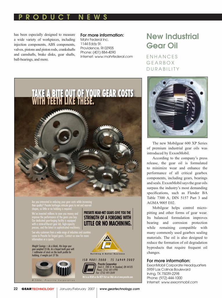
© 2 0 0 6 , P r e s r i t e C o r p o r a t i o n
PRESRITE NEAR-NET GEARS GIVE YOU THE STRENGTH OF A FORGING WITH LITTLE OR NO MACHINING.
We’re as NEAR as the NET! Visit our Web site at www.presrite.com.
I S O 9 0 0 1 : 2 0 0 0 T S 1 6 9 4 9 : 2 0 0 2Presrite Corporation3665 E. 78th St. • Cleveland, OH 44105Presrite Corporation3665 E. 78th St. • Cleveland, OH 44105Presrite Corporation
Phone: (216) 441-5990 Fax: (216) 441-2644
Are you interested in reducing your gear costs while increasing their quality? Presrite hot-forges intricate gears to net and near-net shapes, so little or no hobbing is required.We’ve invested millions to save you money and improve the performance of the gears you buy. Our dedicated gear-forging facility is equipped with a state-of-the-art gear lab, high-capacity presses, and the latest in sophisticated machinery.See why customers from a wide range of industries and countries come to Presrite for forged gears. Contact us now for more information or a quote.
Weight Savings – As a blank, this large spur gear weighed 55 lbs. As a forged tooth gear with 1 millimeter of stock on the tooth profile for hobbing, it weighs just 37 lbs.
TAKE A BITE OUT OF YOUR GEAR COSTSTAKE A BIA BIA TE OUE OUT OF Y OF YT OF YT OOUR GEAR CUR GEAR CWITH TEETH LIKE THESE.

P R O D U C T N E W S P R O D U C T N E W S
www.geartechnology.com January/February 2007 GEARTECHNOLOGY 23
mcin_ad_3/06 3/27/06 2:54 PM Page 1
as intended by the American Gear Manufacturers Association Information Sheet AGMA 925-A03, “AGMA Information Sheet, Effect of Lubrication on Gear Surface Distress.”
AGMA 925 performs a complete analysis of the tribology of spur and helical gears. It calculates the EHL fi lm thickness using the Dowson and Toyoda equation and the fl ash temperature using Blok’s critical temperature theory.
AGMA 925 features include:• Calculation of EHL-specifi c fi lm
thickness and probability of wear.• Calculation of total contact
temperature and probability of scuffi ng.• Calculation of rolling, sliding, and
entraining velocities, and specifi c sliding (slide/roll) ratios.
• Calculation of Hertzian contact stress.
• Screen and hard-copy plots of specifi c sliding, Hertzian stress, fi lm thickness, specifi c fi lm thickness, and contact temperature.
• Programs GEARCALC, AGMA 2001, and AGMA 925 work together in a seamless integrated system that has been optimized using state-of-the-art technology to simplify gear design and analysis.
The software is available as a stand-alone package, or integrated into the CAD programs Inventor, Solid Edge, SolidWorks and Pro/E.
For more information:KISSsoft USA LLC3719 N. Spring Grove Rd.Johnsburg, IL 60050Phone: (815) 363-8823Internet: www.kisssoft.com
Updated Software
I N T R O D U C E D B Y K I S S S O F T A N D G E A R T E C H
KISSsoft AG and GEARTECH Software introduced a new and updated version of GEARCALC, a gear design program originally released in 1986.
GEARCALC requires minimal input data and prompts the user to enter the application, load, material, and heat treatment data for a gearset.
GEARCALC designs maximum-capacity gearsets that have minimum volume and weight. Profi le shift coeffi cients can be selected to maximize pitting and wear resistance, and scuffi ng resistance or bending strength.
AGMA 2001, which replaces AGMA218, rates gears exactly as intended by the American Gear Manufacturers Association Standards “ANSI/AGMA 2001-D04 and ANSI/AGMA 2101-D04, “AMERICAN NATIONAL STAN-DARD, Fundamental Rating Factors and Calculation Methods for Involute Spur and Helical Gear Teeth.”
AGMA 2001 performs the following analyses:
• Life Rating—Given the transmitted power and speed, the pitting life and bending fatigue lives are calculated for a single load and speed, or for an entire spectrum of loads and speeds with the resultant lives determined from Miner’s Rule.
• Power Rating—Given the pinion speed and required design life, the allowable transmitted power based on gear tooth pitting and bending fatigue is calculated for both the pinion and gear. The allowable power rating of the gearset is the minimum of the four power capacities.
AGMA 925, which replaces SCORING+, rates gears exactly

Midwest Motion’s New ControlF E A T U R E S B U I L T - I N R E V E R S I N G S W I T C H A N D S P E E D A D J U S T P O T E N T I O M E T E R
P R O D U C T N E W S P R O D U C T N E W S
24 GEARTECHNOLOGY January/February 2007 www.geartechnology.com
Midwest Motion Products Co. released the MMP20A-24V-RSP motor speed control module. The modular design includes a solid-state PWM switch device that provides bi-directional, open loop, DC motor speed control.
According to the company’s press release, the control delivers 20 amps continuous current at 24 VDC with
a 20–36V range. Measuring 4.5" x 3.1" x 1", the control can achieve the current required to power most brushed DC motors by delivering 240 watts of continuous output power. The latest design enhancement ensures up to 40 A of peak (momentary) current for a peak output power capacity of 480 watts.
The design is enabled to meet the IP-65 standard rating for resistance to harsh environments. The outer casing is brushed aluminum, and two 1/4" diameter thru-holes are provided for easy mounting to any fl at (heat sinking) surface. Sets of four “quick connect” terminals are provided for connecting to power.
The control is designed for operation in applications including pumps, gearmotors, automotive and transportation industries, conveyors, food processing and others.
For more information:Midwest Motion Products 10761 Ahern Ave. S.E.Watertown, MN 55388Phone: (952) 955-2626E-mail: [email protected]: www.midwestmotion.com
Adcole’s New Gage
F E A T U R E S S P I N D L E R E F I N E M E N T S
A new, high accuracy version of the Model 1200 Gage for measuring crank-

M62 OBD Gear GaugeOBD, PD and root diameter inspection �
Re-toolable �
Multiple standard capabilities �Ball or pin contacts �
Shaft and ring-type parts �Manual gear rollers �
Manual or automatic operation �Statistical packages available �
M62 Double Flank Gear RollerManual loading of gear wheels and gear shafts
Measures:� Radial composite deviation� Radial runout� Tooth-to-tooth radial
composite deviation� Tangential composite deviation� Nicks� Optional measurements include
center distance, bore diameter and perpendicularity of bore to gear face
� Optional noise detection
All functional checks can be displayed on the rugged E9066 industrial PC system which offers a linear graphic display with full SPC functions.
Looking for an easy, cost-effective way to check gears?Marposs has the solution – the M62 bench gauge system.It’s accurate, flexible and right at home on the shop floor.
No more dedicated gauges The modular M62 system is quickly re-toolable usingordinary hand tools. You’ll save time and the cost of dedicated gauges.
A single-source for all of your gear inspection needs No one has a more complete line of gear checking equipment than Marposs, so every component is guaranteed compatible. Forget mixing and matching.
If you are looking for easier, more accurate gear checkingplus optional noise detection, take a look at the MarpossM62 bench gauge system. It’s geared just for you.
Check Marposs For All The Gear You Need
Check Marposs For All The Gear You Need
Check Marposs For All
Gear Masters/Gauges� Go-no go gauges� Thread gauges� Spline gauges� Plain masters and master gears
NEED TO CHECK
GEARS?
NEED NEED NEED NEED TO CHECKTO CHECKTO CHECKTO CHECK
GEARS?GEARS?GEARS?GEARS?
3300 Cross Creek ParkwayAuburn Hills, MI 48326-27581-888-627-7677Fax: 248-370-0621E-mail: [email protected]
P R O D U C T N E W S P R O D U C T N E W S
www.geartechnology.com January/February 2007 GEARTECHNOLOGY 25
shafts and camshafts is introduced by Adcole Corp.
The Adcole Model 1200 crankshaft-camshaft gage features proprietary refi nements to the spindle, including signifi cant components and subsystems to achieve accuracies for roundness of better than a quarter micron (0.25µm) for measuring pin journals. This exceeds the 10% rule of the new 2.5 micron roundness tolerance now being introduced by engine manufacturers, according to the company’s press release.
Capable of measuring pin journal roundness, cylindricity, straightness, parallelism, diameter, taper, radial runout, concentricity, and other critical parameters, the Adcole Model 1200 crankshaft-camshaft gage incorporates a laser interferometer measurement system and is built on a base of structural steel. Applications include machine tool performance verifi cation, manufacturing process control, and fi nal parts inspection.
For more information:Adcole Corp.669 Forest St.Marlborough, MA 01752Phone: (508) 485-9100E-mail: [email protected]: www.adcole.com
New Makino G R I N D S , D R I L L S , B O R E S A N D M I L L S
Makino introduced the G5 Grinder horizontal machining center, capable of grinding, drilling, boring and milling
all on the same machine. “The biggest advantage of a
machine like the G5 is the ability to eliminate non value-added time in the manufacturing process,” says Tim Jones, product manager of horizontal machining centers at Makino. “Because you can go from milling to grinding in

www.comtorgage.com
®
Rugged,Reliable,Repeatable
...For 75 Years!
COMTOR SPLINE GAGESInternal or External Spline MeasurementMade Easy!Still using micrometers and pins method?
Comtor Spline Gages make pitch diametermeasurement quick, easy and accurate!
Comtorgage Corporation (since 1928)
Phone: (401) 765-0900 • Fax (401) 765-2846
PitchDiameter
MajorDiameter
MinorDiameter
Rugged, Reliable, Repeatable...For 75 Years!
• Applicable to Spur and Helical Gears!• Gage the Part at the Machine!
PitchDiameter
MajorDiameter
Minor Diameter
COMTOR SPLINE
GAGESInternal orExternal SplineMeasurementMade Easy!
Still using micrometers and pins method?
Comtor Spline Gagesmake pitch diametermeasurement quick,easy and accurate!
®®®®
For all yourgaging needs,Comtorgage it!
Analog Dial or
Digital Readout
P R O D U C T N E W S
26 GEARTECHNOLOGY January/February 2007 www.geartechnology.com
one machine, you’re not only saving on capital equipment but you’re also able to keep the part in the machine, eliminating all the out-of-cut time that does nothing but add to your costs and lead time.”
According to the company’s press release, the G5 is a full fi ve-axis machine, with a B-axis of 0.5/1.5 sec
(90/180), a C-axis at 100 rpm and a 60-tool automatic tool changer that will hold up to a 8.7" (220 mm) diameter grinding wheel.
A two-axis coolant nozzle allows the G5 to accommodate variations in wheel diameter and changes in cutting direction while maintaining specifi c cutting conditions. It also allows for
intermittent rotary dressing, an NC- controlled, hydraulically powered feature that redresses the wheel to reestablish profi le geometry on the cutting wheel.
The G5 features one-piece X-, Y- and Z-covers, proven 1-Series tool changing systems, and a 10-micron cyclonic secondary fi ltration.
Features that assist with thermal stability include an integral spindle with the cooling jacket linked to the bed temperature for part consistency, a coolant chiller to maintain high- precision machining, core-cooled ball screws in all axes, and the use of high- volume, high-pressure coolant.
For more information:Makino North America7680 Innovation WayMason, OH 45040Phone; (800) 552-3288E-mail: [email protected]: www.makino.com
Product News is updated daily online. For the latest product information, go towww.geartechnology.com
ON L I N E
��������������������������
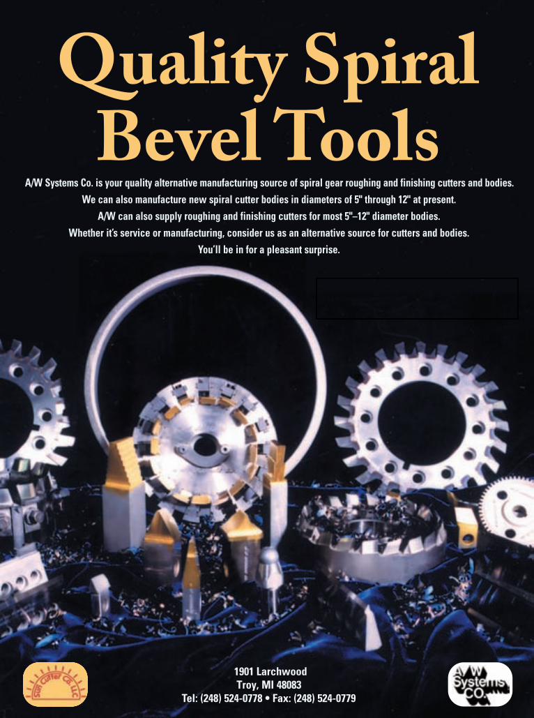
A/W Systems Co. is your quality alternative manufacturing source of spiral gear roughing and finishing cutters and bodies.We can also manufacture new spiral cutter bodies in diameters of 5" through 12" at present.
A/W can also supply roughing and finishing cutters for most 5"–12" diameter bodies.Whether it’s service or manufacturing, consider us as an alternative source for cutters and bodies.
You’ll be in for a pleasant surprise.
1901 Larchwood Troy, MI 48083
Tel: (248) 524-0778 • Fax: (248) 524-0779

28 GEARTECHNOLOGY January/February 2007 www.geartechnology.com
Where to begin? First, know this: no serious discus-sion of the continued scarcity of skilled, up-and-coming engineers and machinists in the gear industry makes sense without acknowledging the bigger picture. That would be the ongoing loss of manufacturing industries and jobs in general that has literally changed the very fabric of the country. And if we are looking where to assign blame, there is no lack of bogeymen at which to point the collective finger. The usual suspects include recalcitrant labor unions; greedy manage-ment; NAFTA and CAFTA; a tilted playing field abroad of low wages and unfair environmental and labor regulations; and an under-performing public education system that does little to encourage young minds that a life in manufacturing is a life well worth living. One more thing to keep in mind: There is as yet no definitive, national consensus on how best to reverse these trends.
As for the gear industry, it must acknowledge and accept its symbiotic relationship with The Big Picture—that its own travails are simply another symptom of a much greater
LABOR PAINS IN THE AMERICAN GEAR INDUSTRY—ANY RELIEF IN SIGHT?LACK OF SKILLED WORKERS MIRRORS U.S. MANUFACTURING’S DECLINE
paralysis—or an infusion of much-needed new blood will never happen.
And yet, gear makers—from job shops to captive shops to OEMs—can take heart in the fact that there are people of influence in the gear industry and other sectors all across this country who have long-recognized the disease and its symptoms, and who are passionately committed to doing something about it. Whether it be grassroots organiza-tions, industry associations, government-sponsored founda-tions or enlightened educational entities, all are dedicated to being agents of change regarding the No. 1 challenge: Restoring the image of manufacturing in the eyes of young people—and educators—as a respectable, financially reward-ing means to make a living and a life. For the many who are involved in the fight, that perception change begins with the schools and our country’s understanding of the influ-ential role they play in preparing our students to compete in today’s global economy. In a sense, it’s the semantics of when a “job” becomes a “career.”
When does a job become a career? “There has been an enormous change in society’s perception of education, particularly at the middle class and blue collar levels, says Geoffrey Ashcroft, director of the Richland, MI-based Gear Consulting Group. “Today, a college education is considered a must for anyone having aspirations of a career, rather than a job. This is strongly encouraged by academia at the high school level, where the prevailing attitude is that, without a college education, there is no respectable opportu-nity for advancement. Blue collar opportunities are rarely dis-cussed, and ‘shop’ classes are regarded as being for the least-bright of the student body—those who are not destined for a ‘good’ college.
“I honestly believe that a large percentage of high school faculty are not aware of what rewarding opportunities there may be in manufacturing, and that the opportunities for advancement in those environments may be considerably better than in other careers. It’s industry’s job to educate our educators in this respect.”
Jack McGuinn, Senior Editor
Schafer Gear’s Jim Shinall (left) providing Brent Cronk some on-the-job training on gear nomenclature.

www.geartechnology.com January/February 2007 GEARTECHNOLOGY 29
Ashcroft, whose company conducts most of AGMA’s on-site training programs, believes the gear industry is having some success in recruiting skilled workers, but inher-ent problems persist.
“There is not, and never will be, a mandatory system of education and certification of machinists and related trades,” he says. “The fact that the gear industry utilizes unique machining processes reduces the supply base of qualified people.”
But those “unique machining processes” are just one reason for the labor shortage. Concurrent with the lack of young workers, an increasingly graying workforce is also at play. According to AGMA industry figures, in 1997, nearly 25% of the gear industry workforce was between 18 and 29 years old. That share dropped to just over 10%; and the organization’s most recent figures reveal that 55% of work-ers are beyond age 44.
Joe T. Franklin, Jr., president of the American Gear Manufacturers Association (AGMA), in Alexandria, VA, shudders to think what the next report will bring.
“The data from 2005 and 1997 paints a striking picture. Our employees are getting older, and fewer younger employ-ees are being hired to replace them,” he says.
Which comes of course as no surprise to him. And as president of AGMA, his concerns are both long- and short-term. The problem he hears most about right now concerns a shortage of workers of any age, which he attributes in part
to manufacturing’s relatively good health, and, like Ashcroft, to the concern younger employees have about the ability of manufacturing to provide them with a longer career.
“Today, most manufacturing industries are booming, and the pressure to find people grew, as the ramp-up from the bottom of the 2000 recession was very quick,” he states. “Greater demand for manufactured products emphasizes the drop in available workers.”
Training requires management commitment. In address-ing that shortfall, Franklin firmly believes AGMA is doing some good things in that regard. He notes there is no short-age of programs, grants and other funding available for training in the gear industry. And it’s those companies that consistently avail themselves of those resources that, not sur-prisingly, are most successful.
“The impact of the (workforce) shortage, and what com-panies are doing to address it, varies greatly,” says Franklin. “Some of our (AGMA) members are very well-positioned with their local high schools, community and technical col-leges, and some universities. These companies are successful and do not appear to have much of a systemic problem. But identifying and hiring good people is an ongoing process for them, not something they do sporadically.”
Beyond that, Franklin believes it’s all about commitment. “Again, like those companies that work with the community colleges and technical schools, it takes a commitment from the company to be successful.”
continued
Schafer’s David Brooke (left) instructs Shane Carpenter at a CNC hobber on the finer points of gear cutting.

30 GEARTECHNOLOGY January/February 2007 www.geartechnology.com
Actions often speak louder than words, and Franklin takes great pride in AGMA’s dedication to real-time, on-site training for gear companies (AGMA membership not required). And the results demonstrate that the need—and desire—are out there.
“We have added the option for individual companies to have an (AGMA) instructor come to their plant for 2–3 days to provide individualized instruction. Most recently, we extended these courses by adding three online components—Fundamentals of Gearing; Inspection; and Hobbing. We have had over 2,000 individuals register to use these courses over the last three years. Interestingly, over 40% of the reg-istrants have over two years of engineering.” (Editor’s note: Please see article on pg. 32 for more on AGMA’s education and training programs.)
But along with AGMA’s efforts, more is needed. According to Stan Blenke, executive vice president for South Bend, IN-based Schafer Gear Works, Inc., and 2006 AGMA chairman, on-the-job training remains a staple for gear makers.
“Today, most gear companies have no choice but to train on the job. AGMA is offering several avenues to assist companies to train their workforce.” In addition, Blenke points out, the association sponsors a gear training school at Daley Community College in Chicago, including the recent addition of advanced-level courses online, as well as stand-alone seminars. But he believes companies—as well as the communities in which they operate—can and should demand more. And be willing to pay for it.
“I believe that every company should invest at least 3% of their annual payroll in employee training,” he says. “All of us need to get involved with Workforce Investment Boards, government-sponsored training programs, and local
educational institutions such as community colleges that offer training in manufacturing skills.
“We must create an atmosphere that nurtures the aspira-tions of today’s workers. Constantly look for opportunities to empower employees at all levels, and to create the corporate culture for a high-performance, exciting place to work.”
Get ‘em when they’re young—and impressionable. “I believe (interest in gear making) starts at an earlier age,” Blenke says. “Whether students plan to go to college or work, they equally need a more rigorous K-12 education, both in academics and in career technical preparation. Much of the support depends in part on the output of the K-12 system.” As for manufacturing’s tarnished image, “Negative images remain, and some people still consider manufactur-ing jobs to be low-paying and dirty,” he says. “The challenge before all of us is how to broadly communicate information about modern manufacturing, and the satisfying careers it has to offer.
“All of us can do more. We must continue to strive to develop a corporate culture that nurtures the aspirations of today’s workers. The best qualified workers are looking for more than a paycheck. They are looking for independence, involvement in decision making, and transferable skills and experiences that will make them valuable to the market, as well as to their current employers.”
Daniel W. Carleton is the manager of the Global Gear Program for Detroit-based American Axle & Manufacturing, Inc. He has another take on the situation—somewhat along the lines of “this not your father’s gear industry.”
“The gear industry has an image problem. College kids, and recent grads, including my own son and daughter, aren’t interested,” he believes. “We have to sex it up a bit—stress the cool stuff, like the Army did with those ads some years ago. It isn’t good to represent ourselves as a bunch of oil-stained, grizzled old farts who talk about the good old days. We need to stress the power aspects of the job. Car and motorcycle racing, the LCAC (Landing Craft, Air Cushion weapons system), sexy stuff that grabs someone’s attention.”
Boiled down, what Carleton refers to is a need that is rec-ognized by any number of associations, institutes, councils and other entities that have taken up the cause of promoting manufacturing’s traditional contributions to our society’s quality of life. What is it? Marketing and awareness cam-paigns. And the more, the better. Getting the word out, as the saying goes, regarding cutting-edge, “clean” manufac-turing technologies and processes, and the role they play in positioning high-tech, high-value-added manufacturing as a destination for young people with a desire to perform mean-ingful work and to be fairly compensated for it.
A need to get our priorities in order. Carleton’s views are doubtless shared by many. And, wittingly or not, they refer in some respects to the point made at the outset—the United States must first get its groove back if anything is to change. It is a need to get back to making things again, and making them here. Cam Drecoll, president of Brad Foote
Geoff Ashcroft conducting an AGMA gear class at Mitchell Community College, Statesville, North Carolina. Attendees at the session were from a variety of gear manufacturers, including some from as far away as Australia.

www.geartechnology.com January/February 2007 GEARTECHNOLOGY 31
Gear Works in Cicero, IL, minces no words in support of that concept. And he has no illusions over who shares a good deal of the blame on how we got to this point.
“There is a general lack of pride in the U.S. for jobs that produce real products. It is somehow looked down upon if an individual works with their hands,” he says. “I think it begins with the expectation that every child is expected to go to college. That viewpoint is expanded in our schools, with little thought to the outcome for those students that will not achieve that goal. It is shocking that, in large cities with a high percentage of students that do not go on to college, there is little thought of their future,” he states. “The educa-tion system has little interest, and even less knowledge, of the needs of the manufacturing community.” And yet, he adds, “A machinist makes more use of trigonometry in a day than most college students do in their entire career.”
As evidenced by his comments, Drecoll believes the school system, as well as government, have something of a learning curve of their own to deal with, particularly as it concerns the legitimacy of manufacturing’s role in a produc-tive society; a role that continues to be well-respected in Europe, where the priorities are different.
“(The dynamic) is much different in Europe,” he says. “A job as a skilled machinist is seen as an honorable career. They take pride in their workmanship and develop their skills. The burden should fall on (our) government to sup-port the manufacturing base in general. This of course has not been a priority for some years, with the illusion that our country can be a service economy. Unless we change our course, the future of our country can be seen easily enough by the decline of Great Britain. The large challenge lies with educating our representatives in the government. This is a steep battle because they are a product of our education sys-tem—the same system that does not respect the need to make real products.”
Geoff Ashcroft also looks with envy at Germany’s regard for manufacturing skills.
“In Germany, the apprenticeship part of an engineer’s resume is considered as important as the academic part, and an engineering degree from a part-time institute can only be undertaken in conjunction with an apprenticeship or internship,” he says. “A graduate engineer with a related apprenticeship/internship is considered every bit as valuable as a bachelor engineer with a pure college degree, maybe more so. German companies employing skilled workers are expected to maintain a quota of apprentices in their com-pany; there is a financial penalty for not doing so.”
So where does that leave things, specific to the gear industry’s image and attendant labor challenge? How in fact do we ingrain in our young people—and the teachers and politicians—that skilled positions in today’s high-tech, high-reward industries are well within the reach of those who can-not afford college, or who simply decide that college is not for them? For the answers, look to the network of commu-nity- and regional-based educational outreach programs and
other initiatives that are springing up all around the country. If manufacturing is to again flourish in America, that is where the seeds are and will continue to be planted.
But what of today’s lack of skilled workers? From where will relief come for that dilemma? Drecoll and the oth-ers quoted here feel that it will have to be more of the same—on-the-job training. But, hopefully, more of it and more effectively. There may even be a silver lining to be found—i.e., a competitive edge for those companies who, as AGMA’s Franklin mentioned earlier, excel at it.
“There is little choice but to conduct on-the-job training,” agrees Drecoll. “There is not another source for (existing) workers. This leaves training as another competitive tool. The companies that can effectively train new (and remedi-ally train existing) workers will be the ones that survive and prosper.”
For more information:Joe T. Franklin, Jr.President, AGMA500 Montgomery Street / Ste. 350Alexandria, VA 22314-1560Phone: (703) 838-0050 Fax: (703) 684-0242E-mail: [email protected]: www.agma.org
Gear Consulting Group, LLCP.O. Box 647Richmond, MI 49083Phone: (269) 623-4993Fax: (269) 623-2055E-mail: [email protected]: www.gearconsultinggroup.com
For a list of upcoming seminars and other training opportunities, visit
www.geartechnology.com/events.htm
ON L I N E

Jack McGuinn, Senior Editor
Despite the many things being done to promote manu-facturing nationwide, there still remains an acute need for gear-specific training, remedial or otherwise. Now in its 90th year, the American Gear Manufacturers Association (AGMA), in conjunction with its AGMA Foundation and Education Council, provides that training via a number of multi-level, computer-based and hands-on teaching modules, and in a variety of settings and locations. All courses are intended to produce a better educated and trained workforce, and to improve a company’s bottom line. In-plant instruction is readily available, and can be designed to suit large and small companies; coursework can be customized to address employees’ particular learn-ing needs. Participants must have a minimum of six months’ experience and be familiar with basic shop safety procedures and rules. Classes are kept to a maximum of 20 students. The curriculum is tailored to benefit just about anyone involved in gearing, including new hires, sales representatives, engi-neers, technicians, management and quality personnel. The programs are available to members and non-members alike. Here is a brief overview of the course offerings, all of which are made possible by a grant from the foundation. The learning begins with the online Fundamentals of Gearing ($25), designed to provide students with a solid foundation for advanced learning. Successful participants of this pre-requisite course earn a certificate of achievement and the opportunity to enroll in upper-level offerings. Next up is Gear Inspection ($150), which teaches the demands of quality assurance as it applies to gearing—why, when, and how. Students and employees learn online sev-eral inspection methods, as well as how and when they are applied. A third online course—Hobbing ($150)—has just been added, and leads the student through the basic princi-ples of hobbing. Fees are the same for AGMA members and non-members alike.
Beyond the online program, AGMA’s In-Plant Basic Course provides classroom and plant-site hands-on training
On-site or Online,AGMATEACHES GEAR BASICS AND BEYOND
and education. The classes are taught at Daley Community College in Chicago, but AGMA also conducts them on-site.
Savvy industry professionals present courses in Gearing and Nomenclature; Principles of Inspection; Gear Manufacturing Methods; and Hobbing and Shaping.
Lastly, it should be added that AGMA’s Education Council welcomes suggestions in the ongoing development of its curriculum, as well as qualified volunteers to teach it. There are many other gear learning resources out there, too many in fact to list here. Following is the contact informa-tion for the AGMA education programs, as well the URL for an article on other schools offering a variety of gear manu-facturing classes:
For more information:Susan FentressAGMA 2007 Gear Education ProgramsPhone: (703) 684-0211E-mail: [email protected]: www.agma.org.
Geoff AshcroftGear Consulting Group, LLCP.O. Box 647Richmond, MI 49083Phone: (269) 623-4993Fax: (269) 623-2055E-mail: [email protected]: www.gearconsultinggroup.com
32 GEARTECHNOLOGY January/February 2007 www.geartechnology.com
Instructors and students take time for a group photo at AGMA’s Gear School at Chicago’s Daley Community College.
To learn about other gear educa-tion resources, see our online-only
article on gear schools at www.geartechnology.com/schools.htm
ON L I N E

34 GEARTECHNOLOGY January/February 2007 www.geartechnology.com
BUT ASSOCIATIONS AND GRASSROOTS ORGANIZATIONS LACK PUBLIC AWARENESS
Where Manufacturing and Education Mesh
Jack McGuinn, Senior Editor
Pick up a newspaper or magazine, tune in the nightly news, or just talk to a neighbor, and what you often hear is that, when it comes to manufacturing, we can’t—or won’t—make it here anymore. Already for too many Americans, that is an unquestioned reality. The good news is that an array of manufacturing associations, partnered with grassroots outreach programs and other like-minded councils and orga-nizations nationwide, are refusing to accept that reality. Fact is, many of these groups have been fighting the good fight for more than 20 years. The problem—one that continues to exist—is that much of their efforts go unnoticed by the gen-eral public.
Following are just two examples of ongoing, collective efforts that should instill hope in Americans and manufac-turers alike that much is being done to recruit, educate and train our young people to compete and excel in today’s—and tomorrow’s—global economy, and in a life in manufacturing as skilled workers, managers, even owners. Their work is
dedicated in part to returning the United States to its once-held position of worldwide dominance in the art of not just selling and marketing things, but in making them as well.
Here is a snapshot of two organizations doing yeoman’s work with their efforts to recruit, educate and train tomor-row’s manufacturing workforce—the Chicago Manufacturing Renaissance Council (CMRC) and Project Lead the Way (PLTW).
Leading the race to the top. The CMRC, founded in 2005, is a consortium of Chicago-based groups includ-ing the Illinois Manufacturing Association, the Tooling Manufacturing Association (local chapter), Winzeler Gear, the Chicago Federation of Labor, the Mayor’s Office of Workforce Development, the Chicago Public Schools and Chicago City Colleges. Their mission: piloting the Chicago region’s need to attract global high-performance, high-value added manufacturing.
In support of that mission, they work to: educate the public regarding the image and societal appreciation of mod-ern, high-tech manufacturing; reform the public education and workforce development systems; enhance government programs for manufacturers and their workers; develop and coordinate policies in support of these initiatives, both state-wide and nationally; and seek to attract “A-list” companies to the Chicago area. The CMRC is in fact an initiative of its larger counterpart—the Center for Labor and Community Research (CLCR), founded in 1982 to respond to the great decline of U.S. manufacturing that began with that decade. But it’s all part of what the CMRC envisions as “leading the race to the top.”
Which brings us to what the CMRC hopes will some-day serve as a crown jewel among its many activities, and as an incubator for a rust-belted community’s commer-cial redevelopment as well as for future undertakings. The Austin Polytechnical Academy, located in the economically depressed Chicago neighborhood of Austin, is scheduled
“None of my peers or my own com-
pany have the caliber of workforce
we need today. We just don’t have the
talent in manufacturing that we need
to compete globally. (The CMRC is)
trying to create an environment that
supports complex, high-end, value-
added manufacturing.”
—John Winzeler, Winzeler Gear

www.geartechnology.com January/February 2007 GEARTECHNOLOGY 35
Where Manufacturing and Education Mesh
continued
to open its doors in 2007. The school will be a part of the Chicago Public Schools system’s Renaissance 2010 initia-tive, instituted to replace under-performing schools through-out Chicago.
Some might reasonably wonder why, given the many hurdles manufacturing already faces domestically regarding the global economy, would the CMRC set up shop in an area like Austin. A central reason is that the Austin community in may ways can be looked at as a microcosm of the sorry state of manufacturing in America. Austin used to be home to manufacturers of all shapes and sizes, accounting for 20,000 industrial jobs. In a scenario all too familiar across the coun-try that began in the early 1980s, most of those companies closed or relocated, taking their well-paying manufactur-ing jobs with them. Neighboring Chicago—“the city that works”—lost 3,000 factories in that decade alone.
Around that same time, in nearby Cicero, IL, more than 50% of the working population found themselves out of work. One of them was Daniel Swinney, a machinist for 13 years, but out of work all the same. Determined to do more than stew about it, Swinney involved himself in a number of community-based, pro-worker and pro-manufacturing endeavors, leading first to the creation of the Center for Labor & Community Research, and in 2005 to forming CMRC, where he serves as executive director and is making, as one former city planner once put it, “no small plans.”
As usual, education is key. “It’s the whole thing of leading the race to the top,” Swinney says. “We do see (the
academy) as a way to transform society.” He adds that with the Austin community’s high school drop out rate of 50%, “Kids turn to crime not because they are criminally minded, but because they really do have limited options, and we need to address that directly. So we see the school as part of a solution that ripples through the community in a way that’s profound and different.”
Transforming society is a tall order, but make no mis-take—Swinney does not see himself tilting at windmills. Rather, he believes that CMRC’s goals for Austin are both realistic and attainable, but a buy-in on the part of the edu-cation community will be crucial. Swinney cites a 2001 CLCR study commissioned to evaluate what remained of the Chicago area’s manufacturing base, that identified a deficient education system as a major problem relative to manufacturing’s depleted workforce. The report, funded by the U.S. Department of Labor, was an alarm bell for the CLCR that led to the formation of the CMRC in 2005 and, ultimately, Austin Polytechnical.
“The study was conducted with the Chicago Federation of Labor, and it said that there was a huge problem in educa-tion, that it was a non-system which serves neither compa-nies nor the broad population because of its poor function-ing. And we proposed a series of reforms, including the need for small schools and academies for manufacturing.”
Those reforms can come none too soon for Winzeler Gear’s John Winzeler, whose concerns for the future as an owner of a gear company are widely shared by others in the
CMRC executive director Daniel Swinney (left) and Winzeler Gear’s John Winzeler.

36 GEARTECHNOLOGY January/February 2007 www.geartechnology.com
industry.“We’re not just doing this because of the schools,” he
says. “It’s something that has been sorely lacking. None of my peers or my own company have the caliber of workforce we need today. We just don’t have the talent in manufactur-ing that we need to compete globally. We (CMRC) are trying to create an environment that supports complex high-end, high-value added manufacturing.”
Both men believe schools like Austin Polytechnical can serve as incubators where students from all backgrounds can receive an education and the hands-on experience that will help them develop career goals beyond simply learning a trade.
“The career paths we’re encouraging are more than just the traditional vocational school,” says Swinney. “We’re encouraging kids to understand the skills needed to go into management, as well as into ownership. Because in small companies there’s a huge problem of succession ownership, where an owner doesn’t have an heir to go into the company and everybody loses. Kids who go to Austin Polytechnical will have an exposure, in terms of their career, to be thinking of not only the most highly skilled technical positions, but also in management and ownership. Which means it is real community development, where they can play an active role in the next generation of manufacturing in Chicago.”
And one of the resources the CMRC relies on to help make that happen is the national pre-engineering curriculum developed by our other spotlighted organization for change—Project Lead The Way. The courses have earned high praise from organizations like the Tooling Manufacturing Association and other sectors, and are intended to provide high school students with an early understanding and appre-ciation of high-tech manufacturing and the opportunities it affords them.
Bart Aslin, SME Education Foundation director, collaborates with Project Lead The Way to introduce junior high students to engineering and manufacturing.

“It’s a universal curriculum that is lab-based, a new approach to industrial arts classes that requires students to work in a problem solving lab environment on a variety of subjects,” says Winzeler. “The beauty of this program is that students who may not be destined for college can go into this program as well. And because they work side by side with pre-engineering students, it brings them along to a much higher level of learning and understanding.”
Put another way, Swinney looks at Austin Polytechnical as not just a springboard to a better life for its underprivi-leged students, but also as an important contributor to manu-facturing’s vital role in a global economy. And now, the kids will have something else they’ve lacked—choices.
“Each kid that graduates will have a high school diplo-ma; they’ll be college-ready if that’s the course they want to go,” says Swinney. “Because we believe modern manu-facturing needs to introduce kids at an early age to a career in manufacturing. And we hope that some kids will take a job after high school, some will seek a higher place in their career path by going to a community or four-year college. The whole idea is that we want them to come back to manu-facturing at some level after they complete their education that’s consistent with their aspirations. Because leading a race to the top requires that we start recruiting the best and the brightest kids from all society to come into manufactur-ing.”
Local outreach goes national. Much like the CLCR, PLTW was started in the 1980s, which marked the begin-ning of manufacturing’s long descent of lost industries, jobs, and the skilled workers to fill them. Today, according to its website, “PLTW is a national program forming partner-ships among public schools, higher education institutions and the private sector to increase the quantity and quality of engineers and engineering technologists graduating from our education system.” PLTW’s pre-engineering curriculum is now taught in 45 states and the District of Columbia.
The program was begun by Richard Blais, at that time chairman of the technology department for an upstate New York school district. Already aware that his students’ prepa-ration for advanced math and science was lacking, Blais had initially formed an advisory board culled from industry local leaders in order to solicit their suggestions on how best to improve his district’s technical-based course offerings. After early success in attracting students to the upgraded course-work, the advisory board received a substantial gift from one of its own members. Richard Liebich, a local business-man and now PLTW’s CEO, made funds available from his family’s Charitable Leadership Foundation. That seed money eventually led to the expanded reach PLTW commands today, with a presence in 1,700 schools nationwide.
As an example, Niel Tebbano, PLTW vice president for operations, cites a partnership with several other like-minded groups that is helping South Carolina in its aggressive efforts to recruit and train its labor pool to meet the challenge of high-tech manufacturing’s worker needs.
www.geartechnology.com January/February 2007 GEARTECHNOLOGY 37 continued
North America
Global Solutions from a Truly Global Company
The only company of its kind with a truly globalmanufacturing presence in all three areas of itscustomer's production: Europe, United States, FarEast. miniGears is the first name worldwide in providingsmall and mid-size precision transmissioncomponents in high volumes produced withconsistently exceptional quality, both by traditionalsteel machining and highly innovative powdermetallurgical PM processes. A team of highly motivated and qualifiedindividuals, recognized for their competence,accountability, innovation capability andresponsiveness to customers' needs, haveestablished miniGears as the reliable partner ingear calculation, engineering design anddevelopment, testing and production of gears andcomplete kinematic mechanisms.
ISO/TS 16949:2002 certified
mG miniGears North America
2505 International ParkwayVirginia Beach, VA 23452 U.S.A.
ph.: (757) 233-7000fax: (757) 627-0944
e-mail:[email protected]: www.minigears.com
Pag C 86x251 20-09-2005 12:02 Pagina 1
“There is a need to attract and retain skilled technologists and engineers across the country,” he says. “The defense industry is especially at risk with its future workforce needs. The South is not immune to this need, but the challenge there I believe is to grow its own workforce, as attracting from a diminishing pool will be a challenge. South Carolina is a great example of a state proactively seeking to improve its education programming to do just that.”
Asked why the public secondary schools have gotten away from schooling students in the industrial arts, Tebbano says compartmentalized thinking—some might call it tunnel vision—results in limited vision and communication.
“Traditional high school courses are taught in silos,” he explains. “There is a silo for math, one for science, etc.; there is very little communication between them. And they are taught by well-intentioned instructors who have never had much work experience outside of teaching, and their understanding of manufacturing and engineering is limited as a result. That’s why courses taught in context, that are rigorous and relevant where the students can apply the math and science in meaningful problem solving, like PLTW, pro-duce significant results.”
The Society of Manufacturing Engineers (SME) part-ners frequently with PLTW in its endeavors. Bart Aslin, the society’s education foundation director, seconds Tebbano’s observations.
“There is now a greater need to attract and train skilled workers to the South as well as nationwide,” he says. “Since many school districts moved away from career technical training, qualified machinists, welders, gear designers, etc., are harder to find.”
To help meet that need, the SME’s educational arm is working with PLTW to combine teaching with week-long day camps to recruit young people for tomorrow’s world of manufacturing. It’s just another example in support of those in the gear industry who stress that the benefits of manufac-turing need to be presented to students at an early age.
Partnering to achieve common goals. “In 2006, the SME Education Foundation partnered with PLTW to estab-lish STEPS (Science, Technology and Engineering Preview Summer) academies for 6th and 7th grade students,” Aslin says. “The purpose of these one-week camp experiences is to introduce young people into the wonders of math, sci-ence, technology and engineering. Each camp will have manufacturing modules as part of the curriculum. Students who attend the camp are encouraged to continue their ‘steps’ through the pipeline by entering the PLTW Gateway to Technology program at their local school. Mentoring will be provided so that students will continue this pathway into high school and beyond. (The foundation) will provide scholarships to students who enter technology careers.”
Despite the very real and justified concern that exists in the nation today over manufacturing’s future role in a shrink-ing world with an ever-growing global economy, there are many “small-world” success stories unfolding across the
38 GEARTECHNOLOGY January/February 2007 www.geartechnology.com
INDUSTRY NEWS
6 0 Y E A R S O F T O P T E C H N O L O G Y
GEAR CUTTING TOOLS
ph: 011-41-32-344-0400 • fax: 011-41-32-344-0404 • www.schnyder.com • [email protected]
w w w . h a n i k c o r p . c o memail: [email protected]
HANIKCORPORATIONPHONE 630-595-7333FAX 630-595-7343
U S D i s t r i b u t o r
7606 Freedom Way • Fort Wayne, IN 46818Tel: (260) 490-3238 • Fax: (260) 490-4093
www.first-gear.com
“YOUR FIRST CHOICE”
Visit our website for more infowww.fi rst-gear.com
ISO 9001 : 2000 CERTIFIED
E N G I N E E R I N G & T E C H N O L O G Y
For Outsourcing Your Gear
Manufacturing
From Prototypes to High Volume
Production

country from which we can learn and be encouraged; too many, happily, to spotlight here. Hearts and minds of young people—and educators—are being influenced in a number of ways that is prompting them to give serious consideration to a career in manufacturing.
“We have a number of people we need to sell on this project—students, the community and parents,” says John Winzeler. “And there’s going to be a broad-based commu-nication project to not only promote (Austin Polytechnical), but to promote the fact that there are meaningful and good-paying jobs in manufacturing, and that (manufacturing) isn’t a dinosaur. That’s a big paradigm shift.”
For more information:Daniel SwinneyChicago Manufacturing Renaissance Council3411 West Diversey / Ste. 10Chicago, IL 60647Phone: (773) 278-5418Fax: (773) 278-5918E-mail: [email protected]: www.chicagomanufacturing.net
Project Lead The Way747 Pierce RoadClifton Park, NY 12065Phone: (518) 877-6491E-mail: [email protected]: www.pltw.org
Bart A. AslinSME Education FoundationOne SME DriveP.O. Box 930Dearborn, MI 48130Phone: (313) 425-3300Fax: (313) 425-3411E-mail: [email protected]: www.sme.org/foundation
www.geartechnology.com January/February 2007 GEARTECHNOLOGY 39
���������������
���������������������������������������������������������������������������������
��������������������������������������������������������������������������������������
��� ����� ���� ���������
630-543-9570 PHONE630-543-7440 FAX 530 Westgate DriveAddison, IL 60101
Overton Gear and Tool Corporation
www.overtongear.com
�������������������������������������������������������������������������������������������������
�����������������������������������������������������������������
�������������������������������������������������������������������� � � � �
� � � � � � � � � � � � � � � ���������������������������������������������������
��������������������������
�
How is your company finding and training skilled workers? Send a
letter to the editor [email protected]
ON L I N E

P.O Box 80 · 11715 Main Street · Roscoe, IL 61073-0080 815-623-2168 · Fax: 815-623-6620 · www.forestcitygear.com
Presenting ...As Forest City Gear heads into 2007, we have some new additions - not only in our family, but in gear equipment and personnel.
New in 2007:A Bourn & Koch/Fellows 450mm CNC Shaper with crowning via servo control and guideless helical special accuracy keeps us in a class of our own.
A Koepfer 200 with high helix capability for worms and gears fully automated takes our productivity to a higher level.
For FCG inspections, we announce our new Wenzel analytical gear checker 600mm with a meter long center support and large bore table to swallow extra long shafts.
Our secondary support team acquires a SUNNEN SV 1005 vertical, automated hone.
In personnel, new staff members Appy Young Mikel and Rustin Mikel have presented Joseph Arnold Mikel as our next generation leader in the making. Watch out Gear World!
•
•
•
•
•
Fred Young holding his grandson Joseph Arnold Mikel.
the next generationof world class gear makers.
Forest City Gear...the most modern fine and medium pitch gear
shop in the world.

42 GEARTECHNOLOGY January/February 2007 www.geartechnology.com
IntroductionThis is Part I of a two-part article.
Part II will be published in the March/April 2007 issue of Gear Techology and presents the results of test pro-grams on the RCF strength of PM steels and discusses the effects on indi-vidual material/process parameters on RCF strength.
The desire to improve gear loading capacity is driven by the automotive industry in order to stay competitive in the global market and environment. Therefore, the gear manufacturing industry is encouraged to develop new, cost-effective manufacturing processes that match or improve current gear life without compromising product reliabil-ity. However, before advanced mate-rials and/or manufacturing processes are introduced into industrial practice, capabilities and risks must be well-documented in order to:
1. Supply the end-user with reliable property data, comparable to well-known and well-documented tradi-
EFFECTSON ROLLING CONTACTFATIGUE PERFORMANCEDr.-Ing. Gottfried Hoffmann and William Jandeska, PhD.
tional materials and/or manufacturing processes.2. Determine the effects of material and/or process parameters on impor-tant design criteria, such as strength under operational conditions, for long-term quality assurance.3. Support research and development for further improvements or for spe-cial applications.
In most cases, these requirements lead to specific product bench testing that provides the confidence and perfor-mance data, but often does not translate well to vastly different applications.
This paper summarizes the results of research and development programs on RCF strength of materials for auto-motive transmission gears. The actual gear contact is very complex and can-not be simulated exactly in any labora-tory test equipment (Ref. 1). Therefore, model testing under specific and well-defined test conditions becomes more important because it allows for sep-arating the effects of contact param-
eters, and for determining the effects of material/process parameters under those specific conditions.
Compared with actual gear testing, model testing reduces test time and costs drastically, but is still too time consuming to study the effect of material/process parameters systematically. Using the eddy current technology to detect failure of the test specimen in very early stages provides additional information about failure mechanisms and crack growth under RCF conditions. Based upon the results of a systematic research program, a procedure was developed that can be used to reduce the number of test samples and allow studying the relative effect of material/process parameters in a very short period of time (Refs. 2–4). The procedure uses the additional information gained by the eddy current technology and can determine changes in RCF strength due to variations of a single parameter.
After describing the most important failure modes under RCF conditions
Management SummaryReducing weight, increasing fuel effi ciency, and reducing costs are the most important forces driving
the dessire to increase power density of highly loaded transmissions for automobiles, helicopters and other applications. The major failure modes of gears are surface damage due to rolling contact fatigue (RCF), and tooth root bending fatigue.
Despite many years of testing of coupons and gears, the mechanism of surface damage by RCF is still not fully understood. Systematic studies of the material/process parameters on RCF strength are costly and time consuming. That is most often a barrier difficult to overcome.
This article summarizes results of research programs on RCF strength of wrought steels commonly used for gear applications and PM steels, including surface-densified PM preforms. Using eddy current technology in connection with a special RCF test rig allows—for the first time—an in situ study of crack initiation and growth before the actual pitting occurs. This technology will not only lead to a better understanding of failure mech-anisms and material behavior, but can also be used to perform systematic tests with a drastically reduced number of test specimens, as well as significantly reduced test time and cost. Hopefully, the application of this procedure will eventually result in material/process RCF-strength relationships that optimize and/or maximize the load carrying capacity of gears and increase transmission efficiency.

www.geartechnology.com January/February 2007 GEARTECHNOLOGY 43
William Jandeska is a consultant with Midwest Metallurgical Ltd. in the field of automotive material, applications and processes. He retired after 34 years at General Motors—20 at the GM Research Lab and 14 as a staff engineer in the advanced materials and processing group at GM Powertrain. Jandeska is a fellow of the ASM Metallurgical Society and APMI—The Powder Metallurgical Institute.
Gottfried Hoffmann is president of V-Tech International, a testing service provid-er and consulting company in general fatigue design and durability studies, located in Milwaukee. In addition, he teaches part-time at several universities in Milwaukee and is a member of MPIF and APMI. Hoffmann was the winner of the 2002 PM World Conference’s Outstanding Technical Paper Award.
Figure 1—Subsurface stress field due to Hertzian contact pressure.
Figure 1a—σxx
Figure 1b—τxy
and summarizing the requirements from the designer’s point of view, the paper will introduce the ZF-RCF test rig and the eddy current technology used in connection with the test rig. It will also present test results obtained with wrought steel and PM steels, and will introduce the newly developed procedure for future test programs.
Characterizing RCF FailureThe three-dimensional sub-surface
stress field. In order to understand the failure of material under RCF condi-tions, it is important to understand the complex three-dimensional stress field caused by elastic deformation of the contact zone. The stress field (in terms of maximum contact pressure) is calcu-lated in real arithmetic using a software package (Refs. 5, 6). Figure 1 shows as an example the three dimensional stress field under line contact in the x-direction (σxx is shown in Fig. 1a) and the shear stress (τxy is shown in Fig. 1b) calculated in the contact zone of the ZF-RCF test rig using the following parameters:
1. Contact pressure = 1,800 MPa 2. Radius of test specimen = 15 mm3. Radius of load roll = 35 mm4. Young’s moduli = 206 GPa5. Poisson’s ratio = 0.36. Coefficient of friction f = 0
The contact force produces a com-plex three-axial stress field within the material (σyy and σzz show similar sub-surface stress distributions as σxx). Only at the line of contact at which τxy = 0 are the stress components iden-tical to the principal stresses σ1, σ2, σ3. Otherwise, magnitude and direc-tion of the principal stresses change at every point. It must be emphasized that all components of the stress tensor
are negative (compressive), with the exception of the shear stress, τxy, which is positive before the line of contact and negative thereafter.
From the viewpoint of fatigue, there are several ways to convert the multi-axial stress field into appropriate fail-ure criteria:
1. Calculating yield criteria such as von Mises (distortion-energy) or Tresca (maximum shear stress), and using the maximum and minimum stress (= 0 in RCF) to calculate stress amplitude and mean stress (Refs. 6, 7).
2. Finding the maximum and min-imum shear stress at every sub-sur-face point and calculating shear stress amplitude and mean stress (= 0 for f=0 due to symmetric shear stress).

face cracks form. Micropitting most frequently occurs in surface-hardened steels in the regime of mixed lubrica-tion. If lubrication is restored, micro-pitting may arrest; otherwise micropits may grow and damage the material.
2. Sub-surface cracks are usually formed in the region of the highest von Mises stress. They first grow parallel to the surface and turn toward the surface, forming the pitting.
3. Core crushing or sub-case fatigue (which should not be confused with sub-surface cracking) occurs deep with-in the material and is usually caused by insufficient heat treatment.
In order to compare the effect of materials and/or process parameters on the RCF strength, it is absolutely essential to identify the failure mode, which in most cases requires intense failure analyses.
Aspects of Material RCF Strength
Analyzing the sub-surface stress fi eld provides design limits for failure under operational loading conditions. If a correlation could be established to other well-known material and fatigue properties, a prediction of lifetime of mating parts in RCF would be possible, and the reliability of gears and transmissions, even under variable loading conditions, could be determined.
The compressive character of the stress state in RCF has been summa-rized as follows (Ref. 5):
1. The tendency to yield is quite small, hence a substantial pressure may be sustained before the onset of plastic-ity.
2. Deformation is very ductile, and even normally brittle materials show considerable ductility.
3. If, as is often the case, all three principal stresses are negative, the like-lihood of brittle fracture is small, since the only possible growth regime of cracks is shear.
4. Crack growth by fatigue is a complicated process, controlled pos-sibly by shear stress as well as ten-sion and considerably influenced by the presence of residual stresses and
bodies in contact, the Young’s moduli, and the contact pressure. This is dif-ferent from most conventional fatigue tests, in which the point or volume of maximum stress is almost independent of the load level. This difference can play an important role for RCF strength under variable loading conditions.
Failure Modes Under RCF Loading
Figure 3 illustrates the three most important failure modes for RCF con-ditions (Refs. 13, 14):
1. Surface-induced cracks. There are two different cracking modes possible:
a) Surface cracks, which usually grow according to the shear component at 30° into the material.
b) Micropitting or gray-stained areas at which many very small sur-
44 GEARTECHNOLOGY January/February 2007 www.geartechnology.com
Figure 2 shows the comparison of all three criteria as a function of sub-surface depth. All three criteria show a similar sub-surface distribution with a maximum stress between 0.15 and 0.3 mm. Differences occur especially at the surface, at which the shear stress is zero. Von Mises and Tresca stress-es are compressive stresses (R = ∞); stress amplitude and mean stress would be half of the calculated data. The shear stress represents the amplitude with σmean = 0 (R = –1).
The sub-surface stress distribution, the position and width of the area of maximum sub-surface stress, and there-fore the volume of material exposed to the highest stress, are affected by the type of contact (point, elliptical, and line), the relative curvature of the
Figure 2—Comparison of Failure Criteria–1,800 MPa f=0.f=0.f
Figure 3—Failure modes in RCF.
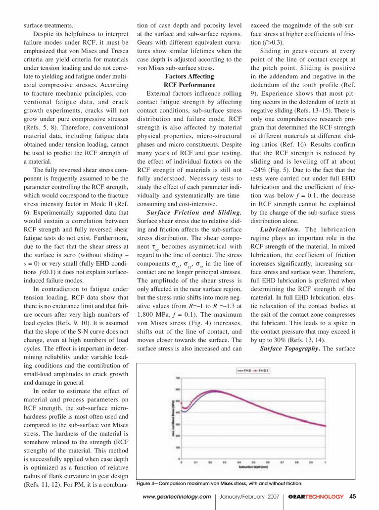
tion of case depth and porosity level at the surface and sub-surface regions. Gears with different equivalent curva-tures show similar lifetimes when the case depth is adjusted according to the von Mises sub-surface stress.
Factors Affecting RCF Performance
External factors influence rolling contact fatigue strength by affecting contact conditions, sub-surface stress distribution and failure mode. RCF strength is also affected by material physical properties, micro-structural phases and micro-constituents. Despite many years of RCF and gear testing, the effect of individual factors on the RCF strength of materials is still not fully understood. Necessary tests to study the effect of each parameter indi-vidually and systematically are time-consuming and cost-intensive.
Surface Friction and Sliding. Surface shear stress due to relative slid-ing and friction affects the sub-surface stress distribution. The shear compo-nent τxy becomes asymmetrical with regard to the line of contact. The stress components σxx, σyy, σzz in the line of contact are no longer principal stresses. The amplitude of the shear stress is only affected in the near surface region, but the stress ratio shifts into more neg-ative values (from R=–1 to R =–1.3 at 1,800 MPa, f = 0.1). The maximum von Mises stress (Fig. 4) increases, shifts out of the line of contact, and moves closer towards the surface. The surface stress is also increased and can
surface treatments.Despite its helpfulness to interpret
failure modes under RCF, it must be emphasized that von Mises and Tresca criteria are yield criteria for materials under tension loading and do not corre-late to yielding and fatigue under multi-axial compressive stresses. According to fracture mechanic principles, con-ventional fatigue data, and crack growth experiments, cracks will not grow under pure compressive stresses (Refs. 5, 8). Therefore, conventional material data, including fatigue data obtained under tension loading, cannot be used to predict the RCF strength of a material.
The fully reversed shear stress com-ponent is frequently assumed to be the parameter controlling the RCF strength, which would correspond to the fracture stress intensity factor in Mode II (Ref. 6). Experimentally supported data that would sustain a correlation between RCF strength and fully reversed shear fatigue tests do not exist. Furthermore, due to the fact that the shear stress at the surface is zero (without sliding – s = 0) or very small (fully EHD condi-tions f<0.1) it does not explain surface-induced failure modes.
In contradiction to fatigue under tension loading, RCF data show that there is no endurance limit and that fail-ure occurs after very high numbers of load cycles (Refs. 9, 10). It is assumed that the slope of the S-N curve does not change, even at high numbers of load cycles. The effect is important in deter-mining reliability under variable load-ing conditions and the contribution of small-load amplitudes to crack growth and damage in general.
In order to estimate the effect of material and process parameters on RCF strength, the sub-surface micro-hardness profile is most often used and compared to the sub-surface von Mises stress. The hardness of the material is somehow related to the strength (RCF strength) of the material. This method is successfully applied when case depth is optimized as a function of relative radius of flank curvature in gear design (Refs. 11, 12). For PM, it is a combina-
www.geartechnology.com January/February 2007 GEARTECHNOLOGY 45
exceed the magnitude of the sub-sur-face stress at higher coefficients of fric-tion (f >0.3).
Sliding in gears occurs at every point of the line of contact except at the pitch point. Sliding is positive in the addendum and negative in the dedendum of the tooth profile (Ref. 9). Experience shows that most pit-ting occurs in the dedendum of teeth at negative sliding (Refs. 13–15). There is only one comprehensive research pro-gram that determined the RCF strength of different materials at different slid-ing ratios (Ref. 16). Results confirm that the RCF strength is reduced by sliding and is leveling off at about –24% (Fig. 5). Due to the fact that the tests were carried out under full EHD lubrication and the coefficient of fric-tion was below f = 0.1, the decrease in RCF strength cannot be explained by the change of the sub-surface stress distribution alone.
Lubrication. The lubrication regime plays an important role in the RCF strength of the material. In mixed lubrication, the coefficient of friction increases significantly, increasing sur-face stress and surface wear. Therefore, full EHD lubrication is preferred when determining the RCF strength of the material. In full EHD lubrication, elas-tic relaxation of the contact bodies at the exit of the contact zone compresses the lubricant. This leads to a spike in the contact pressure that may exceed it by up to 30% (Refs. 13, 14).
Surface Topography. The surface
Figure 4—Comparison maximum von Mises stress, with and without friction.

topography affects the RCF strength by an inhomogeneous distribution of the contact pressure over the contact area. There is a higher pressure in high asperities that can lead to localized plastic deformation and crack initia-tion. Secondly, if lubricant is trapped in surface pockets during over-rolling, i.e., if the dimension of the pocket is small relative to the patch width, the lubricant is compressed by the elastic deformation of the surrounding mate-rial, producing a high hydrostatic pres-sure within the pocket (Fig. 6 a and b) (Ref. 17). Grain boundaries within the pocket are sites for crack initiation. PM materials may additionally be affected when the manufacturing process leaves surface porosity.
Inc lus ions and sof t spo t s . Inclusions and soft spots within the microstructure can act as sites for crack nucleation. Increased purity of the materials shifts the failure mode more and more toward the surface, and the RCF strength is determined by surface conditions. Soft spots, such as retained austenite and Ni-rich phas-es in PM steels, may be detrimental to RCF strength. Under compressive forces, retained austenite may trans-form into martensite, therefore increas-ing compressive residual stresses and fatigue strength. However, if the grains of retained austenite are completely embedded in martensite, the volume increase caused by the transformation from austenite to martensite may lead to microscopic tension stresses which may support crack opening and growth. The effect of Ni-rich phases on RCF strength of surface-densified PM steel will be discussed later in this article.
Residual Stresses. It is common knowledge that compressive residual surface stresses can enhance the fatigue strength of materials (Refs. 18, 19). Most gears are therefore case-hardened, which produces the proper compressive sub-surface residual stresses. However, the sub-surface residual stress distri-bution changes due to rolling contact fatigue (Refs. 12, 20). There are still compressive residual stresses in the near surface region, but they are dras-
46 GEARTECHNOLOGY January/February 2007 www.geartechnology.com
Figure 5—Effect of sliding of RCF strength of gear materials (Ref. 16).
DH ModelJV Model
Relative Volume Change: (VQ–VWQ )
Pre
ssur
e (G
P Q)
14
12
10
8
6
4
2
00 0.05 0.1 0.15 0.2 0.25 0.3 0.35 0.4 0.45 0.5
Figure 6a—Surface crack initiated in a dent.
Figure 6b—Lubricant pressure - volume model.
����
����
����
����
����
����
����
����
���� ����� ����� ����� ����� ���� ����� ����� ���� ���� ����� ���� ������ ����� �
����������������������
��������������� ���������������
�������������������������
����
�����
����
����
����
�
����������������
����������������������������������������������������������
�����������������������������������������������������
�������������������
������
�����������������������������������������������������
��������
Figure 6—Effects of trapped lubricant in surface dents.

dures that would provide both partners with the necessary data in a reasonable time frame and acceptable costs. Those model tests pay off over time because they lead to confidence in the capabil-ity of new materials and technologies, and provide the database for quality assurance and further improvements.
The RCF Test BenchThe RCF test rig used in this
program was developed by ZF Friedrichshafen, Germany, in the early 1960s in order to study RCF at test con-ditions that simulate live gear contacts. The rig was used in extensive research programs in Germany in connection with the Gear Research Institute of the Technical University in Munich (Refs. 16, 23–25) and was used for the first study of RCF strength of PM steels (Ref. 26). A detailed description of the test rig has been published (Refs. 13, 26, 27).
Figure 7 shows the basic principle of the RCF test rig. The test sample is located in the center of the machine and loaded by three load rolls. The contact force is applied by hydraulic pressure of the lubricant, which fur-thermore provides the required amount of oil to produce full EHD lubrication in the contact zone. By changing the gear ratio of the gear drive, the relative velocity of the load rolls in regard to the test specimen (the sliding ratio) can
tically reduced or even turned into tension stresses in the region of max-imum sub-surface von Mises stress. These changes in residual stresses could explain the existence of tension stresses necessary for crack opening and crack growth.
Initial ConclusionsTwo very important conclusions
can be drawn from analysis of failure modes under RCF loading:
1. The RCF strength of a material cannot be predicted. If the microstruc-ture-process-property correlation has not been established, extensive testing is the only way to determine the mag-nitude of the RCF strength and the fac-tors that affect it.
2. Crack initiation is the most important failure criterion, and it is an essential part for determining and analyzing the failure mode. Most RCF test rigs use catastrophic pitting as fail-ure criterion because pitting results in excess machine vibration and can sig-nal stopping. However, the final pit-ting characterizes the end-point of the failure, not the initiation of failure. In order to identify the failure mode after the pitting occurs, intensive microstruc-tural analyses are necessary to iden-tify crack origin and crack propagation path.
Gear Designer RequirementsTransmission designers face a big
challenge: On one hand, they are forced to reduce weight and increase load car-rying capacity of gears and/or power densities of transmissions, and yet find new, cost-effective materials and man-ufacturing processes to be competitive in the global market. Several sets of data are required to perform reliability calculations and to minimize the risk of a premature failure (Refs. 18, 19):
1. The load-time history must be known, either by calculation or by direct measurement.
2. The S-N curve (50% probabil-ity of survival) must be known for the selected material and heat treatment, which is the basis for applying Miner’s rule to determine the cumulative dam-age sum (Refs. 21, 22).
3. The scattering of the fatigue data
must be known to calculate the safe-ty factor for a certain probability of failure.
Data are usually available for tradi-tional materials and conventional heat treatments, based upon long years of experience and extensive tests. In order to realize cost savings offered by newly developed materials or processes, the designer requires not only the standard set of material data, but also the statisti-cal variation of the process over a long period of time. Furthermore, relying on more than a single vendor requires comparable technologies and process control methods used by all suppliers in order to exclude additional data scat-tering due to process variations.
Most companies use statistical methods to keep the manufacturing process in control. However, in order to identify property-relevant process parameters, systematic studies of the effect of those parameters on criti-cal material properties are essential. If those data are not available, exten-sive tests on prototypes under real-life loading conditions are necessary and required.
There is no doubt that the request for systematic investigations of mate-rial/process effects is in the best inter-est of both partners—the manufacturer and the end-user. The burden shifts to the test engineer to develop test proce-
www.geartechnology.com www.geartechnology.com www.geartechnology.com January/February 2007 GEARTECHNOLOGY 47
Figure 7—Principle of the RCF test bench.
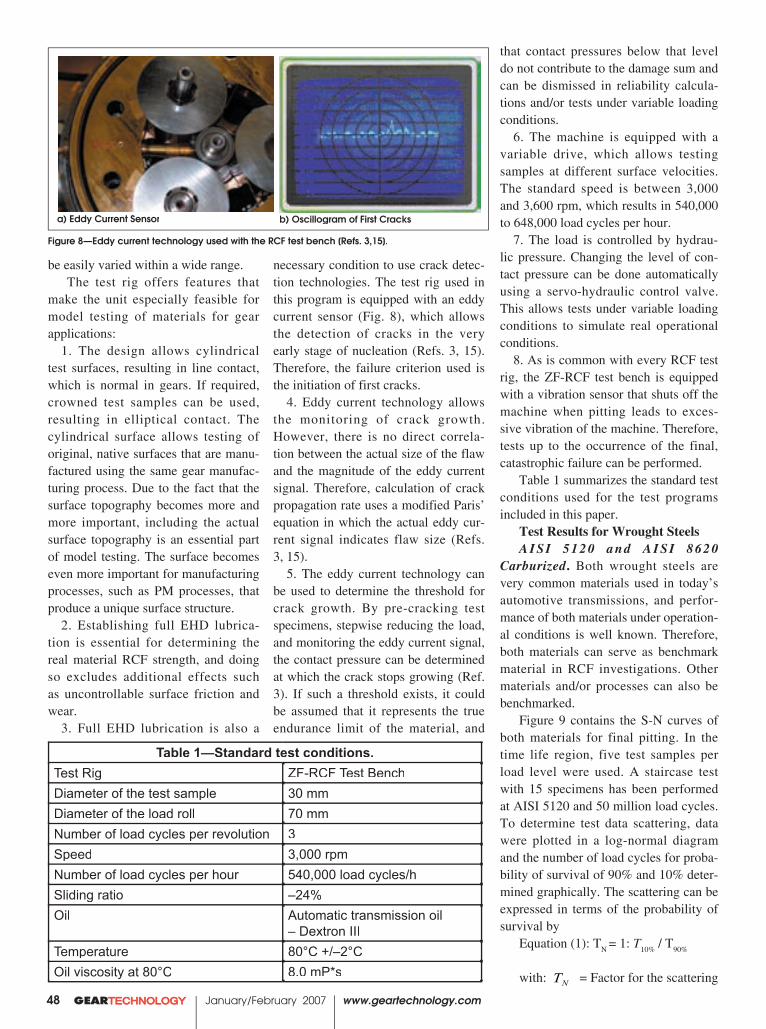
necessary condition to use crack detec-tion technologies. The test rig used in this program is equipped with an eddy current sensor (Fig. 8), which allows the detection of cracks in the very early stage of nucleation (Refs. 3, 15). Therefore, the failure criterion used is the initiation of first cracks.
4. Eddy current technology allows the monitoring of crack growth. However, there is no direct correla-tion between the actual size of the flaw and the magnitude of the eddy current signal. Therefore, calculation of crack propagation rate uses a modified Paris’ equation in which the actual eddy cur-rent signal indicates flaw size (Refs. 3, 15).
5. The eddy current technology can be used to determine the threshold for crack growth. By pre-cracking test specimens, stepwise reducing the load, and monitoring the eddy current signal, the contact pressure can be determined at which the crack stops growing (Ref. 3). If such a threshold exists, it could be assumed that it represents the true endurance limit of the material, and
that contact pressures below that level do not contribute to the damage sum and can be dismissed in reliability calcula-tions and/or tests under variable loading conditions.
6. The machine is equipped with a variable drive, which allows testing samples at different surface velocities. The standard speed is between 3,000 and 3,600 rpm, which results in 540,000 to 648,000 load cycles per hour.
7. The load is controlled by hydrau-lic pressure. Changing the level of con-tact pressure can be done automatically using a servo-hydraulic control valve. This allows tests under variable loading conditions to simulate real operational conditions.
8. As is common with every RCF test rig, the ZF-RCF test bench is equipped with a vibration sensor that shuts off the machine when pitting leads to exces-sive vibration of the machine. Therefore, tests up to the occurrence of the final, catastrophic failure can be performed.
Table 1 summarizes the standard test conditions used for the test programs included in this paper.
Test Results for Wrought SteelsAISI 5120 and AISI 8620
Carburized. Both wrought steels are very common materials used in today’s automotive transmissions, and perfor-mance of both materials under operation-al conditions is well known. Therefore, both materials can serve as benchmark material in RCF investigations. Other materials and/or processes can also be benchmarked.
Figure 9 contains the S-N curves of both materials for final pitting. In the time life region, five test samples per load level were used. A staircase test with 15 specimens has been performed at AISI 5120 and 50 million load cycles. To determine test data scattering, data were plotted in a log-normal diagram and the number of load cycles for proba-bility of survival of 90% and 10% deter-mined graphically. The scattering can be expressed in terms of the probability of survival by
Equation (1): TN = 1: T10% / T90%
with: NT = Factor for the scattering
48 GEARTECHNOLOGY January/February 2007 www.geartechnology.com
be easily varied within a wide range.The test rig offers features that
make the unit especially feasible for model testing of materials for gear applications:
1. The design allows cylindrical test surfaces, resulting in line contact, which is normal in gears. If required, crowned test samples can be used, resulting in elliptical contact. The cylindrical surface allows testing of original, native surfaces that are manu-factured using the same gear manufac-turing process. Due to the fact that the surface topography becomes more and more important, including the actual surface topography is an essential part of model testing. The surface becomes even more important for manufacturing processes, such as PM processes, that produce a unique surface structure.
2. Establishing full EHD lubrica-tion is essential for determining the real material RCF strength, and doing so excludes additional effects such as uncontrollable surface friction and wear.
3. Full EHD lubrication is also a
Figure 8—Eddy current technology used with the RCF test bench [Refs. 3,15].
Table 1—Standard test conditions.Test Rig ZF-RCF Test BenchDiameter of the test sample 30 mmDiameter of the load roll 70 mmNumber of load cycles per revolution 3Speed 3,000 rpmNumber of load cycles per hour 540,000 load cycles/hSliding ratio –24%Oil Automatic transmission oil
– Dextron IIITemperature 80°C +/–2°COil viscosity at 80°C 8.0 mP*s
a) Eddy Current Sensor b) Oscillogram of First Cracks

Table 2—Number of load cycles until fi rst cracks and for crack growth – 5120 and 8620.
Material Carburized
First Crack (load cycles)
Final Failure (load cycles)
Crack Growth (load cycles)
Ratio = fi rst/fi nal (%)
AISI 5120 1.21 x 10⁷ 1.40 x 10⁷ 0.21 x 10⁷ 86 AISI 8620 1.55 x 10⁷ 2.07 x 10⁷ 0.52 x 10⁷ 75
www.geartechnology.com January/February 2007 GEARTECHNOLOGY 49
of the number of load cycles. = Number of load cycles for
10% probability of survival. = Number of load cycles for
90% probability of survival.Using the eddy current technolo-
gy, the number of load cycles for the occurrence of first cracks has been determined for both the materials at a contact pressure of 2,100 MPa. The results are given in Table 2.
The analyses of the first cracks (Fig. 10) reveal that, in both cases, the failure is surface initiated. The cracks show the typical crack growth at 30° from the surface and branching toward the surface. The cracks propagate until they reach the region of maximum sub-surface stress and turn horizon-tally, forming the pitting by branching toward the surface. The failure mode indicates that the surface topography plays an important role and that the true RCF strength of both materials may be higher.
The crack propagation rate (Fig. 11a & b) is very comparable to crack propagation in tension. The Paris’ exponent, which represents the slope of the log (da/dN) vs. log (∆K) plot, is within the range of wrought materials under tension. That might be an indica-tor that even at the compressive stress field, tension stresses may be respon-sible for crack growth. More research is necessary, however, to generalize those findings.
AISI 1060 and AISI 4150—Induction Hardened. Induction hard-ening is a second heat treatment to pro-duce favorable surface conditions for RCF applications. Due to the higher carbon content of the material, the core hardness might be higher compared to carburized steel, and the case depth is deeper as well. Both materials were tested at a contact pressure of 2,100 MPa. The number of load cycles for the first crack and the final pitting are shown in Table 3.
As can be seen from Figure 12, AISI 1060 fails by initiating sub-sur-face cracks at the region of the highest sub-surface stress, while AISI 4150 shows a surface-induced crack that
Figure 9—S-N curves of benchmark materials (AISI 5120 and 8620).
Figure 10—SEM pictures of first cracks.
Figure 10a—AISI 5120 Figure 10b—AISI 8620
turns horizontally at the region of max-imum sub-surface stress. The surface profile (Figure 13) indicates that the surface roughness may play an impor-tant role in the failure mode. Figure 14 shows that the crack propagation rate (expressed by the Paris’ exponent) of the investigated materials is also within the range of those typically experienced under tension loading.
AISI 1060 was tested for the thresh-old for crack growth. Pre-cracked spec-imens (at 1,900 MPa) were tested at
lower load levels, the crack propagation was monitored and the number of load cycles before final failure was record-ed. Table 4 summarizes the results. Figure 14b shows the crack propaga-tion rates at different load levels.
There are some very important con-clusions that can be drawn from the test results:
1.There is a threshold for crack growth. There was no crack growth for more than 10 million load cycles at 1,100 MPa. This threshold level is sur-
T = Number of load cycles for T = Number of load cycles for 10% = Number of load cycles for 10% = Number of load cycles for = Number of load cycles for T = Number of load cycles for 10% = Number of load cycles for T = Number of load cycles for
T = Number of load cycles for T = Number of load cycles for 90% = Number of load cycles for 90% = Number of load cycles for = Number of load cycles for T = Number of load cycles for 90% = Number of load cycles for T = Number of load cycles for

50 GEARTECHNOLOGY January/February 2007 www.geartechnology.com
prisingly high.2. After running the test at 1,100
MPa, the load level was increased step-wise until renewed crack growth could be seen. The load increased by two steps before crack growth occurred. It seems as if load levels at or below the threshold lead to compressive residual stress at the crack tip, which would explain the incubation time for renewed growth.
3.The crack propagation rate at all investigated load levels is very similar and independent of the load itself. This may be another indication that the crack growth is actually governed by tension stresses at the crack tip.
DiscussionThe combination of full EHD lubri-
cation and eddy current technology opens a completely new opportunity to study and optimize materials and/or processes for RCF applications. The detection of first cracks allows the analysis of failure modes. Monitoring the eddy current signal over time gives information about the crack propaga-tion and threshold for crack growth. This offers—for the first time—the chance to study the effects of material and process parameters systematically. It is believed that improvement as well as decline of the RCF strength due to variation of those parameters can be determined with only a few test sam-ples, which would drastically accelerate test programs. The savings in test time is especially evident in the determina-tion of the threshold for crack growth. With eddy current monitoring, this can be done in days, instead of weeks with conventional test procedures, which use load levels required for 100 million or more load cycles until failure.
Figure 11—Crack propagation rate.
Fig. 11a—AISI 5120
Fig. 11b AISI 8620 Fig. 11b AISI 8620
References1. Hoffmann, G., J.A. Rice, “Initiation and Propagation of Cracks in Wrought and Sintered Steels During Rolling Contact Fatigue,” Advances in PM & Particulate Materials, MPIF, 2005, reprinted in APMI PM Industry News Online, Vol. 3, No. 3, March 2006.2. “Development of Tools to Determine the Effect of PM Manufacturing
Crack Propagation - 8620 - case hardened
Square Root Feet V
1.0E.04
1.0E.05
1.0E.06
1.0E.070.1 1.0 10.0
NP/ Λ
P
n = 2.1

www.geartechnology.com January/February 2007 GEARTECHNOLOGY 51
Table 3—Number of load cycles until fi rst cracks and for crack growth.
Material Ind. Hardened
First Crack (load cycles)
Final Failure (load cycles)
Crack Growth (load cycles)
Ratio = fi rst/fi nal
(%)AISI 1060 4.31 x 10⁶ 6.17 x 10⁶ 1.86 x 10⁶ 70AISI 4150 6.70 x 10⁶ 7.50 x 10⁶ 0.80 x 10⁶ 90
a) AISI 1060 b) AISI 4150
Figure 12—SEM pictures of first cracks.
Figure 13—Surface Profile Before Test.
Fig. 14a—Crack propagation rate. AISI 4150 at 2,100 MPa.
Parameters on RCF of Highly Loaded Gears,” NSF– SBIR Phase I Grant No. 0510141, 2005.3. Hoffmann, G., F.G. Hanejko, R.H. Slattery, “Crack Initiation and Propagation in RCF—A New Approach to Understanding Pitting Failure in Highly Loaded Gears,” SAE Technical Papers, SAE 2006-01-0383, 2006, pub-lished in SP-2039, ISBN 0-7680-1774-2, SAE 2006.4. Hoffmann, G., F.G. Hanejko, R.H. Slattery, “Effect of Process Parameters on Crack Initiation and Propagation in Rolling Contact Fatigue,” Advances in PM & Particulate Materials, MPIF, Princeton, 2006.5. Hills, D.A., D. Nowell, A. Sackfield, “Mechanics of Elastic Contacts,” Butterworth-Heinemann Ltd., Oxford 1993. 6. Contact Problems—Software provid-ed by D.A. Hills, University of Oxford, United Kingdom.7. Dieter, G.E. Mechanical Metallurgy, McGraw-Hill, Third Edition, 1986.8. K.-H. Schwalbe, “Bruchmechanik metallischer Werkstoffe,” Carl Hanser Verlag Muenchen-Wien, 1980. 9. Dudley, D.W., “Handbook of Practical Gear Design,” CRC Press, ISBN 1566762189, 1994.10. “Design Guide for Vehicle Spur and Helical Gears,” American National Standard–ANSI/AGMA 6002-B93, AGMA.11. “Fundamental Rating Factors and Calculation Methods for Involute Spur and Helical Gear Teeth,” American National Standard - ANSI/AGMA 2001-D04, AGMA.12. Tobie, T., P. Oster, B.R. Hoehn, “Systematic Investigation of the Influence of Case Depth on the Pitting and Bending Strength of Case Carburized Gears,” Gear Technology, Vol. 22, No. 4, pages 40–48, 2005.13. Hoffmann, G., K. Lipp, “Design for Rolling Contact Fatigue,” 2002 Advances in Powder Metallurgy & Particulate Materials, Conference Proceed ings 2002 P /M Wor ld Congress, Orlando, FL, MPIF 2002.14. Hoffmann, G., K. Lipp, “Design for Rolling Contact Fatigue,” International
Figure 13a—AISI 1060
Figure 13b—AISI 4150

52 GEARTECHNOLOGY January/February 2007 www.geartechnology.com
Figure 14b—Crack Propagation Rate. AISI 1060—different load levels.
Table 4—Final failure of pre-cracked specimen at different load levels (AISI 1060).
Specimen Contact Pressure
(MPa)
1. Crack (load
cycles)
Contact Pressure
(MPa)
Failure (load cycles)
AISI 1060-1 1,900 8.160 * 106 1,900 MPa 9.420 * 106
AISI 1060-2 1,900 9.336 * 106 1,700 MPa 1.335* 107
AISI 1060-3 1,900 5.397 * 106 1,500 MPa 1.348 * 107
AISI 1060-4 1,900 9.600 * 106 1,300 MPa 1.716 * 107
AISI 1060-5 1,900 7.620 * 106 1,100 MPa no crack growth
1,300 MPa no crack growth
1,500 MPa 7.434 * 106
Journal of Powder Metal, p. 33–46, Vol. 39, No. 1,2003.15. “Appearance of Gear Teeth–Terminology of Wear and Failure,” American National Standard - ANSI/AGMA 1010-E95, AGMA.16. Roesch, H. “Untersuchungen zur Waelzfestigkeit von Rollen – Einfluss von Werkstoff, Waermebehandlung und Schlupf, ”1976, Dissertation (Ph.D. Thesis), Technische Universitaet Muenchen, Muenchen, Germany. 17. Zhao, J., F. Sadeghi, H.M. Nixon, “A Finite Element Analysis of Surface
21. Palmgreen, A.“Die Lebensdauer von Kugellagern,” VDI-Z, Vol. 68, No. 4, 1924.22. Miner , M.A. , “Cumulat ive Damage in Fatigue,” Journal Applied Mechanics, Vol. 12, No. 3, 1945.23. Winter, H., H. Roesch, “Einfluss des Schlupfes auf die Waelzfestigkeit von Rollen,” Antriebstechnik, Vol. 14, No. 9, 1975.24 . Kaeser , W. , “Bei t rag zur Gruebchenbildung an gehaerteten Zahnraedern,” Dissertation (Ph.D. Thesis), Technische Universitaet Muenchen, Muenchen, Germany, 2003. 25. Hornung, K. , “Zahnraeder aus Bainitischem Gusseisen mit Kugelgraphit,” Dissertation (Ph.D. Thesis), Technische Universitaet Muenchen, Muenchen, Germany, 1983.26. Lipp, K., “Oberflaechenzerruettung von Sinterstaehlen unter konstan-ter und veraenderlicher Hertzscher Pressung mit ueberlagerter Reibung (Schlupf) ,” Dissertat ion (Ph.D. Thesis), Universitaet des Saarlandes, Saarbruecken, Germany, 1997.27. Hoffmann, G., K. Lipp, K. Michael is , C.M. Sonsino, J .A. Rice, “Testing P/M Materials for High Loading Gear Applications,” International Journal of Powder Metallurgy, Vol. 34, No. 6, 1999.
Pocket Effects in Hertzian Line Contact,”, Journal of Tribology, p. 47-54, Vol. 122, No.1, January 2000.18. Stephens, R.I., A. Fatemi, R.R. Stephens, and H.O. Fuchs, “Metal Fatigue in Engineering,” John Wiley & Sons, Inc., Second Edition, 2001.19. Sonsino, C.M., “Fatigue Design Concepts,” ISBN: 1-878954-91-1, MPIF Princeton, 2003.20. G. Kotthoff, “ Neue Verfahren zur Tragfaehigkeitssteigerung von gesinterten Zahnraedern,” Dissertation (Ph.D. Thesis), RWTH Aachen, Germany, 2003.

OCTOBER 7–10, 2007 • DETROIT, MICHIGAN, USAExhibit at GEAR EXPO 2007 8 Join the largest collection of gear experts in the world at GEAR EXPO 2007 in Detroit — the center of the power transmission industry.
Sell to New Markets 8 Key buyers from more than 30 countries will be on hand to view your products and services.
Introduce Buyers to Your Product Line 8 Visitors to GEAR EXPO can boost your bottom line — more than 80% have buying and specifying authority.
The Decision Is Easy! Sign Up Today!www.gearexpo.comOwned and Produced by the American Gear Manufacturers AssociationContact us via e-mail: [email protected] or call: (703) 684-0211
SINK SOME TEETH INTO YOUR SALES!

FACE GEARS:Geometry and Strength
54 GEARTECHNOLOGY January/February 2007 www.geartechnology.com
Ulrich Kissling and Stefan Beermann
IntroductionFace gears have existed for centuries—the
Chinese implemented them on wagons, and the Romans used them in water and windmills. Around the middle of the last century, much attention was given—especially in the United States—to development of the theory and machining of involute face gears. Calculations used in manufacturing proved to be extraor-dinarily complex. Face gears were at this time installed in relatively lightly loaded gear boxes for transmitting motion. Around 1990, an effort was undertaken in the Netherlands by Crown Gears, which produced face gears under the product name “Cylkro” drive (Ref. 1). Further development was also undertaken in the United States and Japan (Refs. 2, 3).
Face gear projects were also initiated in German academic institutes, with the aim of developing a strength calculation based on experimental data. The further development of manufacturing techniques, most of all in grind-ing, has allowed for the successful use of face gears in high-performance gear systems.
The main advantage of the face gear over the bevel gear is the axial freedom of the pin-ion. With face gears, there is no need for the exact axial positioning of the pinion, as is required of a bevel pinion if an ideally distrib-uted contact pattern is desired. This freedom proves especially advantageous in precision technology. In extremely lightly built drives, which give rise to significant deformations in the housing, the contact region is not signifi-
Dr. Stefan Beermann, is vice president of KISSsoft AG, hav-ing previously served from 1996-1997 as KISSsoft product manager for L. Kissling & Co., AG. His 2000 doctorate thesis was “Simulation of Vibrations in Gearboxes Applying Spectral Simulation.”
Dr.-Ing. Ulrich Kissling is managing director and CEO for KISSsoft AG, the software company he founded in 1998. He was previously managing director of L. Kissling Co. SA, a Swiss gear manufacturer. Kissling is chairman of the gear committee for the Swiss Standards Association and a v o t i n g m e m b e r f o r Switzerland in the ISO TC 60 committee. He has also writ-ten extensively on calculation procedures for machine design and power transmission, and has conducted numerous semi-nars, courses and lectures on gear technology.
cantly influenced. For this reason, the helicop-ter industry has dedicated great effort to imple-ment this type of drive.
The manufacturing of face gears, most of all for large series, proves to be very chal-lenging. The large research and development expense attached to the development of meth-ods for the machining of such gears required a dedicated and costly commitment to engi-neering and licensing of the product, which of course affects pricing. The relatively high cost was greeted by a subdued market response, but there nevertheless exists a clear interest in the product. Crown Gears has since suspended its development of face gears, and the work has been taken up by ASS AG of Switzerland.
For the manufacturing of face gears not using hobbing or shaping (i.e., by plastic mold-ing, sintering or pressing), the tooth form of the face gear will be defined by direct calcula-tion, and a tool developed for its manufacture.
Calculation of the Geometry and the Tooth Form
A face gear has similarities to a rack in a continual arc (Fig. 1). In contrast to this sim-plest of all drives, the engineer fights against the restrictions which emerge, due to the bend-ing of the rack form during the sizing of a face gear set. Because the tooth flanks of a straight-toothed face gear must run parallel to a radius—the contacting pinion having flanks parallel to its own axis—it follows from con-tact theory that the pressure angle must reduce from the outer to inner radius. The following
Management SummaryThere are three distinct gear types in angle drives. The most commonly used solutions are bevel and worm drives; a less-often implemented alternative is a face gear drive. This solution—with its specifi c advantages and disadvantages—is discussed in this document.

www.geartechnology.com www.geartechnology.com www.geartechnology.com January/February 2007 GEARTECHNOLOGY 55
equation (for our purpose considering only straight tooth forms here) applies as the central formula for the determination of the geometry for face gears
(1)
where: z2 is the number of teeth of the face gear,α2 is the pressure angle of the face gear at
diameter d2d2d ,αn is the pressure angle of the spur-pinion at n is the pressure angle of the spur-pinion at n
the reference circle, m
n is the module of the pinion (Ref. 1).
In the example in Figure 2, the pressure angle changes from about 39° on the outer diameter to around 10° on the inner. This leads to very steep tooth flanks on the internal side, through which the involute becomes very short—and is represented on only a small part of the tooth height—followed by an undercut which further reduces the usable region. On the outer part, the tooth gets a pointed tip. As a result, minimum and maximum diameters are determined, which limit the total possible tooth width of the gear. This represents a dis-
tinct difference compared to a bevel gear pair. While bevel gears can transmit a higher torque through a higher tooth width, the face gear pair is limited to the region forming acceptable tooth contact conditions with a spur gear.
By clever choice of width offset bv (Figure 3), i.e., through a shift of the tooth width cen-ter opposite the reference circle, the maximum permissible tooth width can be optimized.
When sizing a face gear, it makes sense, after fixing a minimum and maximum pres-sure angle, to next determine the inner and outer diameter. By setting the outer and inner diameter as reference diameter, Equation 1 is redefined for the range of module available.
(2)
Beyond considering the raw numbers, it is helpful to also consider a graphical representa-tion of the teeth. With a little experience, the engineer will determine from a 2- or 3-D graph (for example, Figs. 1 or 2) in which direction the significant parameters should be changed in order to reach an optimum solution.
Figure 1—3-D view of a face gear in KISSsoft, produced by the calculation of the mesh process of a face gear with a shaping cutter.
2
22 cos
cos�� nn zmd � , (1)
nzdm
��
coscos
2
maxmin/2maxmin/2maxmin/ � (2)
2
22 cos
cos�� nn zmd � , (1)
nzdm
��
coscos
2
maxmin/2maxmin/2maxmin/ � (2)

56 GEARTECHNOLOGY January/February 2007 www.geartechnology.com
Figure 3—Definition of the tooth offset bv and the addendum change hake/i at the inner and outer diameters.
The overwhelming number of applications use straight-toothed face gears. Helical face gears can, with the appropriate design pro-cedure, offer benefits in strength and noise development.
In contrast, the problem emerges that the
flanks are no longer symmetric in that the left flank no longer corresponds to the right. In practice, this implies that a possible undercut on a flank appears earlier on one side than on the other. In Figure 2, for example, a dis-tinct undercut can already be seen on the right
Figure 2—Plot of the pairing of a cylindrical helical with a face gear. Three sections of the face gear are illustrated. Inner: Violet; Middle: Green; Outer: Red.

www.geartechnology.com January/February 2007 GEARTECHNOLOGY 57
gear flank at the inner diameter, while on the left flank there is only a very slight undercut. Likewise, the pressure angle in the example is different, being 31.2° (on the middle section) on the left, and 29.5° on the right flank of the tooth.
These differences on the flank have an influence on the strength so that transmissible power is different, depending on the direction of rotation. If only one direction is to be used, then the flank to be used can be optimized without consideration of the opposite flank.
Experience teaches that theoretical geom-etry considerations, which describe a flank form in terms of the involute function, lines and arcs, always tend to a limit sooner or later. Tried-and-tested, and much safer, are tooth form calculations which are based upon simu-lation of the meshing process, or, better yet, on a simulation of the machining process. In these simulations, the trajectory of a point on the active surface is traced (Fig. 4) until the speed normal to the surface of the tool is a zero point (Fig. 4). These positions are potential places of contact on the tooth form surface. The actual points of contact must then be determined, removing any so called “imaginary” points whose relative motion satisfies the contact cri-teria but whose position is actually outside of
Figure 4—Trajectory (blue) of the surface point of the pinion (red) relative to a face gear surface (green). The posi-tion with zero relative speed defines a potential contact point.
the material on the gear surface. Attempting to identify the difference between real and imagi-nary points presents the greatest difficulty to this approach. Apart from the usual standard algorithms for the classification of points in a plane, empirical approaches must be employed which recognize the known properties of the required tooth form in order to achieve a well-defined tooth form with a degree of certainty.
The calculation of the 3-D tooth form of the face gear can, on the basis of traditional production methods—meshing with a pinion-like shaping cutter—be defined in this way (Fig. 1). The 3-D body can be output in a vari-ety of graphics formats so that, in any arbitrary CAD system, a form can be constructed in order to manufacture face gears using other production methods such as injection molding, sintering or form forging.
The 2-D representation is well-suited for the checking of undercut or pointed teeth in a face gear. In the previous diagram (Fig. 2), the tooth forms at the inner-, mid-, and outer-gear diameters of the face gear are simultaneously drawn. If the gear is rotated in discrete steps, the meshing conditions at each position can be checked throughout the meshing cycle. In the case of extremely pointed teeth or unac-ceptable contact ratio, the tooth height can be

58 GEARTECHNOLOGY January/February 2007 www.geartechnology.com
shortened (Fig. 3), analogous to the approach in hypoid gears.
In order to reduce sensitivity from errors in the axis position or axial distance, crown-ing can be produced on the tooth flanks. This can be applied relatively easily to face gears produced with a pinion-like shaping cutter (or equivalent milling tool) which has one or two teeth more than the intended pinion. A com-parison of the tooth forms shows the influence of the higher tooth number of the cutter on the crowning of the tooth form. For a large-width offset, bv, of the face gear, the crowing can be shifted to one side.
Each transverse section through the spur with the corresponding part of the face gear basically corresponds to a rack and pinion sys-tem. Based on the rack theory, it is possible to calculate the pressure angle, contact line and contact ratio in each section (Fig. 5).
Strength CalculationFollowing are various approaches for the
strength calculation of the face gear:1) Development of proprietary calculation
methods—for example, a finite element meth-od (FEM) calculation combined with a pres-sure evaluation.
2) Adjustment of the method for the resis-
tance calculation of spur/helical gearing (e.g., ISO 6336).
3) Adjustment of the method for the resis-tance calculation of bevel gearing (e.g., ISO 10300).
The first possibility is not practical, in that it is possible to spend years conducting a com-prehensive series of measurements. The devel-opment of ISO6336, for example, has taken decades to prepare, being founded upon mul-tiple theoretical and practical—by means of test rigs—work programs.
The third method is relatively simple, but leads in the end to ISO 6336. The ISO 10300 calculation method converts the bevel geom-etry in the first step to an equivalent helical gear, and then derives calculation methods directly from ISO 6336.
This leaves only the second approach—the adjustment to a suitable standard for spur/helical gears (e.g., ISO 6336), to which can be added some of the more similar con-cepts of the ISO 10300. Critical points to consider in doing this are that the contact ratio from inner to outer diameter changes to such an extreme that only a calculation based on contact ratio at the mid-diam-eter is carried out (analogous to bevel
Figure 5—Position of the contact lines on the face gear flanks.

www.geartechnology.com January/February 2007 GEARTECHNOLOGY 59
gears), or that only the average of the three calculations at the inner, mid and outer diam-eters is considered. Furthermore, all the impor-tant dimensions of the spur/helical gearing being used are in conjunction with the plane of the reference circle. But in a face gear, the reference circle lies in a plane at right angles to the reference circle of the pinion. Certain for-mulae must therefore be adjusted to cope with the concept of an infinite radius. This problem is identified by the analysis of rack gearing
Calculation to ISO 6336The Crown Gears method of calculating
the strength of face gears is based upon the spur/helical calculation according to ISO 6336 (Ref. 1). Because of the curvature in the path of contact, there is a raised total contact ratio due to the so-called lead overlap ratio. This is somehow comparable to the overlap ratio in helical gearing in which helical-toothed face gears contain an overlap ratio that is given by the helix angle β. A virtual helical angle, βv, can be derived from the curvature of the contact line, with which the effect can be con-sidered using the helix angle factors Yβ and Zβ. Transverse contact ratio εα becomes the value used in the middle of the tooth width. The derivation of the face load coefficient KHβKHβKH
and transverse coefficient KHα, according to methods from ISO 6336, cannot be directly implemented for face gears. Again using the Crown Gears calculation, the values are usu-ally set to KHβKHβKH = 1.5 and KHα = 1.1, so that a similar approach to the calculation of bevels (ISO 10300) is chosen.
Calculation to ISO 10300As previously mentioned, the use of the
strength calculation according to ISO 10300 for bevel gears can be an appropriate alterna-tive. Face gears belong to the class of bevel gears, and can be thought of as a limiting case, with cone angle 0° (pinion) and 90° (face gear). The strength calculation for bevel gears is conducted on the basis of an equivalent spur/helical gear, the spur/helical having the same tooth form as the bevel. In the case of the face gear, this gives the virtual tooth number Z
1vZ
1vZ = Z
1Z
1Z and Z
2vZ
2vZ = ∞ for the pinion and gear,
respectively.A validation with Crown Gears calcula-
tions, and the methods of ISO 6336 or ISO 10300, produces a very good match in that deviation at the root and flank safety factors in all cases is under 10%, with most under 5%. However, because the Crown Gears method is restricted concerning the correct length of the
Figure 6—Course of stress curves of a face gear: geometry of the face gear corresponds to the test gear of Akahori (Ref. 2).

60 GEARTECHNOLOGY January/February 2007 www.geartechnology.com
contact lines, the ISO6336 method is recom-mended.
Load distribution over the tooth width.The load distribution at the root and on the flank can be calculated very accurately by using an FEM analysis. But this requires a comparably large time investment, while a very quick method for the estimation of the Hertzian pressure and root stress is given by performing the calculation in discrete steps as a rack. In doing so, the course of the pressure
at the pitch point and the root stress (calcu-lation procedure according to ISO 6336 for racks) can be defined, assuming a constant lin-ear load, across the tooth flank (Fig. 6).
Akahori carried out investigations of ground case-hardened face gears (m
n=2.75
mm; b=18 mm; bv=5 mm; Z=28:85) (Ref. 2).
The tooth root stress, which has been measured via strain gage, provides a good match with the calculated course of tooth root stress for the face gear (Fig. 6). Also, the photo of the tooth
Table 1—Calculated safety factors for the face gear (Ref. 2).
Calculated factor: Root Pinion Root Gear Flank Pinion Flank Gear
With KHβ = 1.5, KHα = 1.1: 0.43 0.34 0.77 0.88
With KHβ = 1.0, KHα = 1.0: 0.70 0.56 0.98 1.13
Figure 7 (Top & Bottom)—Scoring pitting safety factor against flash and integral temperature and speed at tip and root. Geometry of the face gear corresponds to the test gear of Akahori (Ref. 2).

massive problems with scoring in the higher sliding speed region (Ref. 2). It is therefore necessary to consider adding similar calcula-tions to detect a scoring problem. As previ-ously described in the stress distribution, a reasonable possibility can be the calculation of the scoring safety factor according to German Institute for Standardization (DIN) 3990 in discrete steps. Figure 7 shows the course of the scoring safety, according to criteria of flash and integral temperature across the tooth flank.
In order to arrive at a realistic calculation, all steps should be calculated at the same tem-perature. In working through the calculations, it can be shown that the factor according to the integral temperature contains many jumps. This occurs if the point E of the contact line is E of the contact line is Eclose to the pitch point. The re-calculation of the flank temperature at point E relative to the E relative to the Eaverage flank temperature with the formulae of (DIN) 3990, becomes somewhat imprecise. On this principle, the use of the flash temperature criterion is recommended for face gears.
SummaryThe face gear is certainly a challenging
component to design, but its use in some appli-cations is significantly more advantageous than an equivalent bevel gear solution. Through the availability of software for sizing face gears and their associated tooling, it is now possible to efficiently overcome special calculation and manufacturing problems associated with tooth forms of this type in arriving at a practical, alternative solution.
References1. Basstein, G. and A. Sijtstra. “New develop-ments concerning design and manufacturing of face gears.” Antriebstechnik, 32 (1993), Nr.11.2. Akahori, H., Y. Sato, Y. Nishida, and A. Kubo. “Test of the durability of Face Gears.” Organi di trasmissione, 2002, Nr.12 oder MTP2001-Fukuoka, The JSME Int. Conference, 2001, Japan.3. Lewicki, D.G., R.F. Handschuh, G.F. Heath, and V. Sheth. “Evaluation of Carbonized Face Gears,” The American Helicopter Society 55th Annual Forum, Montreal, Canada, 1999.
www.geartechnology.com www.geartechnology.com www.geartechnology.com January/February 2007 GEARTECHNOLOGY 61
flank after 107 load cycles shows a pitting con-dition, which corresponds well with the region of higher Hertzian pressure on the tooth flank in Figure 6 (Ref. 2).
Theoretical Safety FactorsAs with every gear, a validation of the
strength is given as safety factors for pitting and root strength. In order to evaluate these factors, it is important to know the mini-mal required values. This is a general prob-lem associated with machine construction. Minimum safety values can (according to the conditions and requirements) be very different, and should be determined most of all on the basis of experience and proven results from a test rig. In cases where nothing similar is known, the following values can be used as a starting point:
Minimum root safety factor (SFminSFminSF ): 1.4Minimum flank safety factor (SHminSHminSH ): 1.0Regarding face gears, well-documented
results are readily available. During the mea-surements of Akahori (Ref. 2), a distinct pit-ting was observed at a driving torque of 675 Nm after 107 load cycles. Cracks or breaks in the root did not appear. A validation accord-ing to ISO 10300, when using the factors dis-cussed above (KHβKHβKH = 1.5 and KHα = 1.1), gives factors in Table 1 by calculation. These factors are impressively low. In Akahori’s testing, the gear used was a ground face gear of very high precision. The face load co-efficient chosen in precision. The face load co-efficient chosen in this case was set much too high. A validation this case was set much too high. A validation through ISO 10300 with factor KHβKHβKH =1.0 gives a flank safety factor of 1.0, and root safety fac-tor of 0.80. The flank safety factor corresponds roughly to expectation, but the root safety is so low that a break in the root can be expected. Evidently the calculation method is very con-servative in this case. Based on the analysis above, where obviously the gear must be hard-ened, it can be cautiously interpreted that, for industrial applications with face gears made from steel, the root strength is less critical than in spur gears, and presumably the safety fac-tors can in fact be set as follows:
Minimum root safety factor (SFminSFminSF ): 1.0Minimum flank safety factor (SHminSHminSH ): 1.0Calculation of the scoring safety factor. The calculation of the scoring safety factor
is difficult because of the very different slid-ing velocities, and the changing flank pressure across the tooth flank. In the Crown Gears calculations, no check for scoring is conducted (Ref. 1). On the other hand, Akahori reported
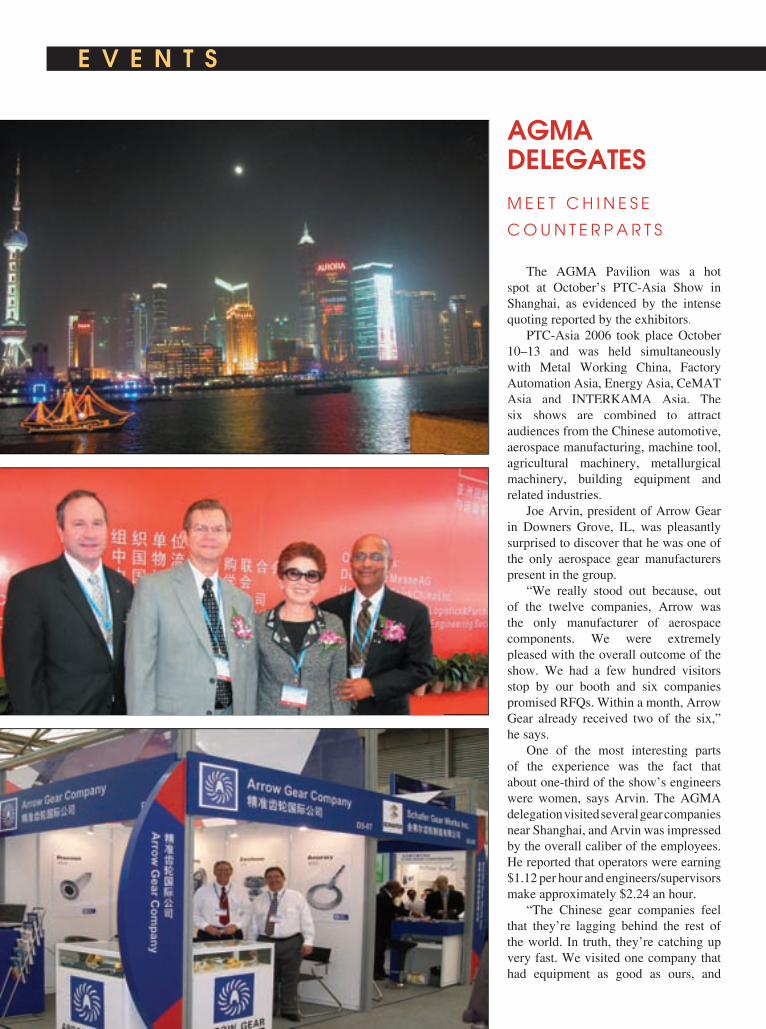
E V E N T S E V E N T S
The AGMA Pavilion was a hot spot at October’s PTC-Asia Show in Shanghai, as evidenced by the intense quoting reported by the exhibitors.
PTC-Asia 2006 took place October 10–13 and was held simultaneously with Metal Working China, Factory Automation Asia, Energy Asia, CeMAT Asia and INTERKAMA Asia. The six shows are combined to attract audiences from the Chinese automotive, aerospace manufacturing, machine tool, agricultural machinery, metallurgical machinery, building equipment and related industries.
Joe Arvin, president of Arrow Gear in Downers Grove, IL, was pleasantly surprised to discover that he was one of the only aerospace gear manufacturers present in the group.
“We really stood out because, out of the twelve companies, Arrow was the only manufacturer of aerospace components. We were extremely pleased with the overall outcome of the show. We had a few hundred visitors stop by our booth and six companies promised RFQs. Within a month, Arrow Gear already received two of the six,” he says.
One of the most interesting parts of the experience was the fact that about one-third of the show’s engineers were women, says Arvin. The AGMA delegation visited several gear companies near Shanghai, and Arvin was impressed by the overall caliber of the employees. He reported that operators were earning $1.12 per hour and engineers/supervisors make approximately $2.24 an hour.
“The Chinese gear companies feel that they’re lagging behind the rest of the world. In truth, they’re catching up very fast. We visited one company that had equipment as good as ours, and
AGMA DELEGATESM E E T C H I N E S E
C O U N T E R P A R T S

E V E N T S E V E N T S
www.geartechnology.com www.geartechnology.com www.geartechnology.com January/February 2007 GEARTECHNOLOGY 63
Immediate Opportunities inChallenging Aerospace Careers.
Apache by Boeing,
transmissionsby Purdy.
TEAMAPACHEProud Supporters ofAmerica’s Military.
INNOVATIVE, DYNAMIC,CREATIVE,CHALLENGING.JOIN US!
The Purdy Corporation is a leader in manufacturing flight critical Jet engine and rotor components including
gears, gear boxes and transmissions for OEMs and the United States Government.
Aerospace manufacturing opportunities offering stability, job satisfaction and growth are available
in the following areas of expertise;
• Gear Management - Aerospace Manufacturing
• CNC Programming (Unigraphics) -
Gear Box Housings, High Speed Machining,
• Gear Engineering - Process, Planning & Manufacturing
• Gear Machining - Spiral Bevel and Parallel Axis • ID/OD Grinding
• Gear Metrology • Gear Box Assembly and Testing
Excellent benefit and relocation packages.An Equal Opportunity/Affirmative Action Employer.An Equal Opportunity/Affirmative Action Employer.
Take your career to a whole new level, contact us at860.649.0000 Ext. 226 or e-Mail to [email protected]
Arrow Gear has about $2–3 million in new equipment.”
Brian Slone, business unit manager of metrology systems at Process Equipment Co. in Tipp City, OH, noted that the on-site visits to Chinese gear plants were one of the most useful parts of the Shanghai experience. Chinese gear manufacturers, he says, are attracted to the Process Equipment inspection systems’ ease-of-use, com-petitive pricing, technical service and Chinese-language user interface, which allows them to train operators quickly.
“In a market where reverse-engineering is no longer a dirty word, the unknown gear measurement program was also seen as a desirable tool. Above all, though, it was the Chinese language interface that reset the bar in their minds,” he says.
AGMA has participated in the show for the past several years, but this is the fi rst year the association sponsored a pavilion for member companies as well
as companies manufacturing mechanical power transmission equipment. Del-egates included representatives from Arrow Gear, Bevel Gears India, Cleveland Gear, Gear Motions Inc., Process Equipment Co., Schafer Gear Co. and Seitz Corp.
Share Your News with Our Readers!
Gear Technology1425 Lunt Avenue
Elk Grove Village, IL [email protected]
or call (847) 437-6604

C A L E N D A R
March 6–9—UTS Gear Design & Manufacturing. UTS facility, Rockford, IL. The course aims to provide a fundamental understanding of spur and helical involute gear geometry, teach attendees to apply gear design concepts and develop a working knowledge of UTS software tools. Other topics to be covered include gear fundamentals, gear
tooth forms, gear geometry, standard proportions, quality, gear modifi cations, gear design considerations and the gear design process. Students also have the opportunity to tour Gleason Cutting Tools and Forest City Gear. An optional Basic TK Solver course is offered on TK Solver course is offered on TK SolverMarch 5 to familiarize students with the program for equation solving,
manipulation of units and creation of tables and plots in math models. The TK Solver Course is $295 and the Gear TK Solver Course is $295 and the Gear TK SolverDesign Course is $1,250. For additional information, contact UTS on the Internet at www.uts.com.
March 13–15—Expo Manufactura. Cintermex, Monterrey, Mexico. Metalworking and manufacturing event designed for manufacturing personnel. Registration is free and takes place on-site. For more information, contact E.J. Krause & Associates by telephone at (301) 493-5500 or by e-mail at [email protected].
March 15–17—AGMA/ABMA An-nual Meeting. Marco Island Marriott Resort, Marco Island, FL. Discussions include Dr. Mike Bradley’s Report on the Economy, American Politics: Looking Toward 2008 & Beyond; The Worker of the Future: Why the Profi t Future of American Business is Tied to the Quality of America’s Future Workforce; and ExtraPreneurship: Reinventing Industrial Work to Compete in a Flat World. $895 for the fi rst registrant from an AGMA/ABMA member company, $795 for additional registrants from an AGMA member company. For more information, contact the AGMA on the internet at www.agma.org or by telephone at (703) 684-0211.
March 26–29—WESTEC 2007.Los Angeles Convention Center, Los Angeles, CA. Exhibitors include advanced machine tool, cutting tool and accessories, manufacturing technology, and emerging technology companies. The event is sponsored by the Society of Manufacturing Engineers and showcases automation and assembly solutions for the aerospace, automotive, biotechnology, chemical, computer, cosmetics, defense and electronics industries. Registration is free. For more information, visit the show’s website at www.sme.org/westec.
64 GEARTECHNOLOGY January/February 2007 www.geartechnology.com
Coming Soon 2007��������������������������
��������������������������������������������������������������������������������������������������������������������������������� ������������������������������������������������������������������������� ������������
������������������������������������������������
��������������������������������������������������������
�������������������������������������������������������������������������������������������������
For more InformationCall Ryan King at 847-437-6604


Except as otherwise noted, all of the trademarks referenced herein are owned by Ticona or its affiliates.Fortron is a registered trademark of Fortron Industries LLC.Except as otherwise noted, all of the trademarks referenced herein are owned by Ticona or its affiliates.Fortron is a registered trademark of Fortron Industries LLC.Except as otherwise noted, all of the trademarks referenced herein are owned by Ticona or its affiliates.
© 2006 Ticona
8040 Dixie Highway, Florence, KY 410421.800.833.4882 www.ticona.com
Great Minds!Put our polymer and application brainpower to work for you.Ticona is the world leader in plastic gear technology. For over 30 years, our gearheads – better knownas gear technology experts – have helped to dramatically reduce the cost, weight and noise of gear drivesfor countless applications.
Great Minds!Great Gears!Great Polymers!Ask the Ticona Gearheads™
Great Gears!• Reduce noise• Boost efficiencies• Lower cost• Increase design flexibility• Eliminate the need for lubricants• Resist chemicals and corrosion
Great Polymers!Celanex®Celanex®Celanex thermoplastic polyester (PBT)Celcon®Celcon®Celcon and Hostaform®Hostaform®Hostaform acetal copolymer (POM)Celstran®Celstran®Celstran and Compel ® long fiber reinforced thermoplastics (LFRT)Fortron®Fortron®Fortron polyphenylene sulfide (PPS)GUR ® ultra-high molecular weight polyethylene (UHMW-PE)Riteflex®Riteflex®Riteflex thermoplastic polyester elastomer (TPE)Vectra®Vectra®Vectra liquid crystal polymer (LCP)
N E W S
www.geartechnology.com January/February 2007 GEARTECHNOLOGY 67
Explosion at FalkK I L L S T H R E E E M P L O Y E E S , I N J U R E S 4 6
An explosion at Milwaukee-based Falk Corp. occurred on December 6, killing three employees and injuring an additional 46.
Falk employees Daniel Custer, Curtis Lane and Thomas LeTendre were killed in the explosion.
The blast shook the surrounding area, overturned cars in the parking lot and blew out windows of nearby companies in the industrial park.
Despite the blast damage, the majority of the facility remains structurally sound. Shops 1 and 2 and the foundry were cleared during an initial inspection.
Nearly 500 employees returned to work December 18 and limited production began again. At an evening meeting held December 19 for employees and spouses at the Wisconsin State Fair Park Expo Center, company leaders said they anticipated bringing back all 750 workers and resuming full-scale operations at the Canal Street site by late January.
“With the help of local contractors, the City and, of course,
N E W S N E W S
Moventas
R E C E I V E S O R D E R F O R M A S S D E L I V E R I E S O F W I N D T U R B I N E G E A R S T O A C C I O N A
Moventas signed a supply agreement for substantial deliveries of wind turbine gearboxes to Spanish turbine manufacturer ACCIONA Windpower.
Moventas plans to increase its gearbox deliveries for Acciona Windpower’s 1.5 megawatt wind turbines. The order more than doubles Moventas’ annual delivery volume of main gear units of type PLH-1000 from 2007–2009. Moventas’ gearboxes have been part of Acciona’s wind turbines since the beginning of their turbine production in 2003.
Moventas designs, manufactures and markets power transmission solutions and services for the process and energy industries.
Acciona Windpower is a subsidiary of Acciona Energia, a renewable energy company. In wind power, the company has put 4,122 turbines into service in 153 wind parks. Through its subsidiary Acciona Windpower, it produces 1.5 megawatt wind turbines using in-house technology in three manufacturing plants.
Philadelphia Gear O P E N S D U B A I S A L E S O F F I C E , A P P O I N T S M A N A G E R
Philadelphia Gear Corp. opened a new sales offi ce in Dubai, United Arab Emirates in November. James Aston was appointed Middle East regional sales manager.
According to the company’s press release, Aston will be responsible for setting up the Middle East offi ce and handling sales and service related to gear products and services within the oil and gas, petrochemical and power generation industries throughout the region. At the outset, Aston will focus on marketing the Philadelphia Gear, Western, WesTech and Delaval brands, and coordinate with Middle East distributors.
Aston was engineering sales manager for Sabroe Industries in Denmark, covering 19 Middle East countries. Prior to that, he was national sales manager for Kooltech in the U.K.
our valued employees, we are taking signifi cant strides toward restoring Falk’s facilities,” said Dave Doerr, Falk president. “Some equipment is already up and running, and we began assembling and manufacturing component parts on Monday [December 18]. Replacement equipment and supplies have been ordered and, this past weekend, the company shipped its fi rst orders since the accident.”
Further updates can be found on the company’s website at www.falkcorp.com.
Donations can be sent to:Curtis Land Memorial FundLandmark Credit Union955 Lexington Dr.Oconomowoc, WI 53066
Thomas LeTendre Children’s College FundAlex Flynn & Associates SC1233 N. Prospect Ave. Milwaukee, WI 53022
Falk Families Survivors’ FundRexnord Industries LLC4701 W. Greenfield Rd.Milwaukee, WI 53214Attn: Treasurer

68 GEARTECHNOLOGY January/February 2007 www.geartechnology.com
N E W S
Eicher Motors
A C Q U I R E S B M C D E W A S ’ G E A R U N I T
Eicher Engineering Components, the automotive component division of Eicher Motors Ltd., acquired the
www.qcamerican.com
� � � � �
Form Wheel Gear Grinder YK7332-A$336,000
Limited Time Sale Price(Lease options starting at $5,931/mo.)
Worm Wheel Gear Grinder YK7236-A$392,000
Limited Time Sale Price(Lease options starting at $6,290/mo.)
Deliveryeek Average
(max very, any model, 28 weeks)
QualityISO TS-16949 - 2002
Experienced
Shaanxi Qinchuan Machinery Development Co., Ltd. has selected American Broach & Machine Co. to offer sales, tech support, service and engineering for their world class gear grinding machines in North America, under the brand name QC American.
Call For Info
(734) 761-5021
(maxISO TS-16949 - 2002
Call For Info
(734) 761-5021
introducing
mr bill holifieldnational service
manager
Deliveryeek Average
QualityISO TS-16949 - 2002
ExperiencedISO TS-16949 - 2002
“QC American” Gear Grindersa division of american broach & machine co., ann arbor, michigan
AMT ReportsM A N U F A C T U R I N G T E C H N O L O G Y C O N S U M P T I O N O N B E S T P A C E S I N C E 2 0 0 0
September U.S. manufacturing technology consumption totaled $407.21 million, according to the American Machine Tool Distributors’ Association (AMTDA) and the Association For Manufacturing Technology (AMT).
This total, as reported by companies participating in the USMTC program, was up 31.9% from August, and up 43.1% from the $284.47 million reported for September 2005. With a year-to-date total of $2,815.34 million, 2006 was up 26.2%, compared with 2005.
These numbers and all data in this report are based on the totals of actual data reported by companies participating in the USMTC program.
“Strong sales at September’s International Manufacturing Technology Show pushed year-to-date consumption to its
largest lead over 2005,” says John J. Healy, AMTDA President. “It now looks likely that 2006 will post the best results for U.S. investment in advanced manufacturing equipment since 2000.”
The USMTC report, jointly compiled by the two trade associations representing the production and distribution of manufacturing technology, provides regional and national U.S. consumption data of domestic and imported machine tools and related equipment. Analysis of manufacturing technology consumption provides a reliable leading economic indicator, as manufacturing industries invest in capital metalworking equipment to increase capacity and improve productivity.

www.geartechnology.com January/February 2007 GEARTECHNOLOGY 69
N E W S N E W S
Dewas, India-based transmission gear unit of the British Motor Car Co. Ltd. (BMC)
Siddhartha Lal, managing director and CEO of Eicher Motors, says “Our engineering components business has a portfolio of products ranging from differential and transmission gears to gear boxes.”
Eicher Motors Ltd. entered into a business purchase agreement with BMC on Oct. 20, 2006, and formally completed the transaction Nov. 1.
mG miniGears
N A M E D O N E O F E U R O P E ’ S F A S T E S T G R O W I N G C O M P A N I E S
mG miniGears SpA of Padua announced that it has been listed No. 272 among the fastest growing European companies included in the 2006 Europe’s 500 Listing, the annual ranking of high-growth, job-creating companies published by Europe’s 500-Entrepreneurs for Growth and supported by Microsoft and KPMG.
The 500 dynamic companies have enjoyed sustained growth since 2002, boosting employment at an average annual rate of 16%, and sales at 18%.
Despite the challenging business environment, these companies have created nearly 150,000 jobs across Europe in three years.
mG miniGears has increased employment by 20%, and turnover by 22%, adding 83 new jobs.
The 2006 listing refl ected the emergence of winners from many of the new EU member states for the fi rst time, including Estonia, Hungary, Latvia, Lithuania, Poland and
N.A. Woodworth“Quick-Pitch” Diaphragm
FEATURES:• Jaw change in 60 seconds• Accommodates any number of gear teeth• Compliance for tooth space variation• Optional synchronizing pins for auto-load• Standard “pull-back” action• Centrifugal force compensation for higher speeds• Minimal maintenance, no sliding parts• Lightweight assembly• Ideal for hard turning and grinding applications
2002 Stephenson Hwy., Troy, MI 48083 Phone: 800-544-3823 • Fax: 248-743-4401
www.itwworkholding.com • [email protected]
Only Requires Half-Turn to Lock Jaw In Place
Fixed Length Wedge PinRequires No Adjustment
Workholding Worldwide
ISO9001:2000 Registered Company

Motion Control
tage of our technicalcapabilities in advance ofyour quote with a feasi-bility study. Our experi-ence in design, materialsand manufacturingthrough a detailedassessment also can pro-vide you with a proposedsolution that saves youtime and cost in the end.
Try us on your nextprogram. We offer rapidprototype delivery foryour qualification needs.Precipart is ready for you.
Precipart is more thanjust a gear company.Our engineered motioncontrol devices explorethe surface of Mars andvisualize the human bodyin diagnostic probes.
A leader in developingmotion control solutions,Precipart has served themedical/surgical, dental,optical, robotics, oil field,aviation, avionics,telecommunications,scientific instrumentationand defense industriessince 1979.
We design and manufac-ture all types of gearsand gearboxes for actua-tors, gear motors, RVDTs,and instrumentation usedfor demanding applica-tions in varying environ-ments. Through ourexpertise and experiencesupported by comprehen-sive resources, we’reready for your nextassignment.
Our total value-addedapproach also is a win-win. You can take advan-
We are ISO 9001-2000and AS 9100A registered.
PRECIPART CORPORATIONA Member of the GemNetwork90 Finn CourtFarmingdale, New York11735Tel: 631 694 3100Fax: 631 694 4016www.precipart.com
EngineeredSolutions For The World Around Us
Engineered Ad 3/4/06 12:05 PM Page 1

www.geartechnology.com www.geartechnology.com www.geartechnology.com January/February 2007 GEARTECHNOLOGY 71
N E W S
Price: $155 plus shipment - Order online at www.mfn.li/bookswww.mfn.li/books or E-mail to [email protected]
- 21 Different Topics
- Trade Show with 22 Booths
- MFN Trainers & Guest Speakers from 9 Countries
- FAA-approved Basic, Intermediate and Advanced Courses
- Hands-on Training for Flap Peening
- Hands-on Training for Residual Stress Measurement Equipment
10th International MFN Shot Peening Workshop & Trade Show in Florida, USA
Date: 15th - 17th May 2007
Register online at
www.mfn.li/workshops
For more information & registration form see current MFN issues or check online at
www.mfn.li/workshopsYou can also request an information
package at [email protected]
Edited by Steven Baiker Authors
Francois-Xavier AbadiePeter BeckmerhagenMohammed BelasselMichael BraussRay FontanaNai Puay GuanHeribert GrayGiovanni Gregorat
1st Edition
publishing
house
Foreword byArshad Hafeez
Shot Peening
A Dynamic Application and Its Future
Markus HalderWolfgang HennigPaul HuytonMarco KlijsenGuy LevasseurEckehard MüllerJames PineaultShlomo Ramati
MFN is a Partner in Education in Nadcap
New Book
On Shot Peening!
Topics:Topics:introduction to peening and theory, peening intensity, effect of peening, Almen saturation curves, peening coverage, exposure time, trouble shooting, process documentation, masking solutions, workpiece fixtures, shape & size inspection of peening media, cut wire, cast steel shot, ceramic media, specifications, shaded strips, audits by third parties, peening equipment components, air & wheel peening, machinery types and application examples, hole peening, flap peening, peen forming, optimization of shot peening for fatigue critical applications, residual stress, XRD
measurement, quantative characterization of the shot peening process, etc.
“Each chapter in this book is written by an acknowledged expert in the field of shot peening. I would highly recommend it for anyone interested in using this application to improve the performance of structural components, particularly those that are expected to experience
subsequent fatigue loading.”
Prof. Lothar Wagner, Acting Director, Institute of Materials Science and Engineering, Clausthal University of Technology, Germany
Philadelphia GearN A M E D O N E O F P E N N S Y L V A N I A ’ S B E S T P L A C E S T O W O R K
Philadelphia Gear Corp. was honored at an awards ceremony Nov. 28 as one of the state’s best places to work.
According to the company’s press release, the program recognized 100 companies in total—50 medium-sized companies (25-250 employees) and 50 large companies (251 or more employees). Philadelphia Gear was recognized in the medium-sized category.
“It’s a tribute to the extraordinary people who work here,” says Philadelphia Gear CEO Carl Rapp. “We’ve spent the past fi ve years collectively retooling our offering to the marketplace and trying to get better for our customers. It’s great to see the tangible results of these efforts resonate with so many people. I am very proud of our team’s ability to focus on strategy and deliver results, but even prouder of how our people treat one another. That’s what makes Philly Gear a great place to work.”
The competition focused on an evaluation of workplace policies, practices, philosophy systems and demographics, as well as a survey measuring employee experience.
Slovenia. They joined the Czech Republic, which was listed for the fi rst time in 2005. France and Germany received high rankings in Western Europe.
Company CEO Alexander Bossard says, “This growth has been achieved in a diffi cult market environment. It shows that the team is able and wants to face up to the diffi culties and to take the opportunities. Companies like mG miniGears grow fast and manage to sustain their growth, making them excellent role models for Europe’s future.”
mG is one of 29 companies in the manufacturing sector that qualifi ed for Europe’s 500.
“Mid-size businesses are the champions of economic growth in Europe. Today’s mid-market companies are using technology to empower their workforce, recognizing that people are at the core of success—a trend that will see continued growth in Europe for years to come,” says Gabriel Indalecio, Microsoft EMEA senior director of Small and Midsize Solutions and Partners.
Awards were presented to the winning companies in recognition of their performance and contribution to European economic welfare by European Commission vice-president, Günter Verheugen, in charge of Enterprise and Industry, at the Europe’s 500 Awards on Nov. 25, in Vienna.

Two Specialty Coating FacilitiesJ O I N M E T A L I M P R O V E M E N T
Metal Improvement Co. acquired two coating facilities from Diversifi ed Coatings Inc. of Ridgeway, PA, that specialize in the application of high-performance coatings for automotive industry components.
The two new facilities are located in Fremont, IN, and Ingersoll, Ontario. The 72,000-square-foot Fremont facility previously operated as Allegheny Coatings – Fremont, and the 44,000-square-foot Ingersoll facility as Diversifi ed Coatings – Canada.
According to the company’s press release, both utilize highly automated spray coating lines for high-performance coating for corrosion, oxidation, lubricity and cosmetic applications.
The primary business is the spray application of galvanic high-performance coatings for automotive brake rotors, ball studs and stamping, but the facilities also provide application services to the farm equipment, trailer, military, marine and construction equipment industries.
New Sales ManagerF O R R E I S H A U E R N A M E D
Jeff Hocevar has been appointed national sales manager for Swiss-based Reishauer AG’s North American diamond and CBN tool division. Schooled in industrial engineering at the University of Wisconsin and Six Sigma Green Belt-certifi ed, Hocevar worked previously at Greenlee Diamond Tool Co. as a customer service representative before joining their sales engineering/abrasives division. His new duties at Reishauer will include the sales and distribution of all direct- and reverse-plated super abrasive products for gear/thread and non-gear-related applications, grinding wheels, and workholding equipment.
Says Reishauer vice president Dennis Richmond, “Jeff brings a keen technical understanding of the plating process with him, along with his intense organizational skills.”
Jeff Hocevar
Magazine Subscription Request�� I want a free subscription to The Shot Peener.
Please send it to the address below.
Please print or attach your business card:
Name ______________________________________Title __________________
Company __________________________________________________________
Address __________________________________________________________
City _____________________State_______ Zip________Country ____________
Telephone ________________________ Fax ____________________________
Email Address ______________________________________________________
Fax: (574)256-5222Mail: The Shot Peener56790 Magnetic Drive, Mishawaka, Indiana 46545 USA
The Shot Peener: www.shotpeener.com/EI/tsp/index.html
Do your gears need:
More strength?Longer life?Shot peening is the answer.To learn more, subscribe to The Shot Peener. The Shot Peener is dedicated to raising the awareness and apprecia-tion for the shot peening process.
GT
72 GEARTECHNOLOGY January/February 2007 www.geartechnology.com
N E W S

www.geartechnology.com www.geartechnology.com www.geartechnology.com January/February 2007 GEARTECHNOLOGY 73
N E W S
MIDWEST GEARMIDWEST GEAR& TOOL, INC.
15700 Common Rd.Roseville, MI 48066
CONTACT:CRAIG D. ROSS(586) 779-1300
FAX (586) [email protected]@[email protected]
SKILLS NEEDEDGear Technician/Engineer
JOB DESCRIPTION Gear Enigineer needed to print, reverse engineer,
and collect information on gearing
• Design new gears, reverse engineer existing gears, check gear drawings.
• Failure analysis of gears and other components. Write reports and analyses of fi ndings for failures.
REQUIREMENTSFormal Requirements/Certifi cations of Job B.S. in Engineering - preferred 5 years experience in heavy industrial gearingUTS software - preferredMetallurgical background – preferredTechnical writing skillsExcellent communication skillsMust be self-drivenProfi cient with word processing and spreadsheets
Company: L&H Industrial IncLocation: US-WY-GilletteBase Pay: $50,000.00 - $65,000.00 /YearBonus: $1,000.00Employee Type: Full-Time EmployeeReq’d Education: 4 Year DegreeReq’d Experience: More than 5 YearsReq’d Travel: NegligibleRelocation Covered: YesPosted Date: 11/6/2006
Contact: Ed Roche
Email: [email protected]: (307) 682-7238 Fax: (307) 686-1646
Internet: www.lnh.net
Global Leader in Rebuilding & Manufacturing for the Mining Industry
Tom Lang R E T I R E S F R O M K A P P
Thomas J. Lang, vice president and general manager of Kapp Technologies, left the company at the end of 2006 to pursue personal interests.
Roger PennycookR E C E I V E S P T D A L I F E T I M E A C H I E V E M E N T A W A R D
Roger A. Pennycook, former president of Boston Gear and former vice president of Textron Fluid & Power Co., was the 17th recipient of the Warren Pike Award for lifetime achievement in the power transmission/motion control industry.
Pennycook, retired after a 20-year career, received the award at the association’s annual industry summit.
According to the association’s press release, the award is not automatically given every year and is presented only if a qualifi ed individual is identifi ed. Nominees are reviewed by the offi cers of the PTDA’s board of directors and the manufacturer council chair. Once a candidate passes this review, he must be approved by the full board of directors.
Pennycook spent most of his career at Boston Gear, eventually becoming president. He completed his career at Textron Fluid & Power before retiring in 2004. He served on the PTDA Manufacturer Council from 1984 to 1988 and as chair in 1987. He was a board director for two years and served on the steering committee for four.
Gerry Ferris, Boston Gear’s vice president of global sales, says “Roger is a very customer-focused individual who knows how to grow and improve relationships. His passion for our partnership with distribution spread throughout our organization.”

A Gear's Homeis its Castle.
Use Deco Precision Gearcases.
Precision gears deserve precision quality gearcases.
Deco Products will cast, machine, powder-coat, and plate complete assemblies to your specifications.
Call our engineers now for assistance.
506 Sanford Street, Decorah, IA 52101
www.decoprod.com�[email protected]
800.327.9751 • 563.382.4264 • Fax: 563.382.9845
N E W S
74 GEARTECHNOLOGY January/February 2007 www.geartechnology.com
AGMA
P R O M O T E S C H A R L E S F I S C H E R
AGMA announced the appointment of Charles S. Fischer to replace recently retired Bill Bradley as VP of the association’s technical division, effective March 1.
Fischer joined AGMA in 1994, after 19 years at Philadelphia Gear. As a senior engineer and assistant manager of AGMA’s technical division, his responsibilities included liaison activities with many AGMA technical commit tees, standards editing, educational meetings and assisting with the ISO stan dards development process.
In making the appointment, AGMA president Joe T. Franklin, Jr. said, “AGMA is fortunate to have an employee like Charlie who is well-versed in both the technical activities of AGMA and in business management issues. In his 20 years with AGMA, Bill Bradley has broken new ground for the association and the industry, especially on the international front. I know Charlie will continue AGMA’s long tradition of technical excellence and, because of his knowledge of business issues, will be key to better integration of the technical solutions with the industry’s business needs.”
AGMA Chairman Stan Blenke praised the decision noting, “Promoting Charlie is well-deserved recognition of his contributions to the industry and the association and, more so, to his vision for both the department and the AGMA as we move forward.”
Ed Lawson, chairman of AGMA’s technical division executive committee, said, “From working with Charlie on a number of projects, I know him to have a great love for our industry and for AGMA. I know his detailed understanding of the technical needs of the industry and the capabilities of the AGMA will be of great value.”
Charles Fischer
Lang started Kapp Technologies’ Boulder, CO facility in 1991. According to Kapp’s press release, the company now has 40 employees and conducts business throughout North America under the name Kapp Technologies.
Lang’s duties will be assumed by James Buschy and Bill Miller. Buschy, manager of technical services, will assume Lang’s position as VP and general manager on Jan. 1. Miller was named vice president of sales for Kapp in September.
In 1978, Lang began working as a production engineer for General Cable Corp. He later moved to the gear industry as a development engineer at Advanced Energy Technology. In 1989, he and a business partner started Aerocom Industries, a gear and special form manufacturing company.
www.James-Engineering.com4732 Pearl Street, Boulder, CO 80301
Ph. (303) 444-6787 Fax (303) 444-6561
4 Deburring Models!462 Bench top 562 Enclosure with dust control762 Large gear enclosure (40" dia.)962 Fully automatic system (3,500 parts per day)
We now offer wet
deburring!!
Factory Direct Sales
462 562
Gear Deburring
N E W S

COMING SOON!PTE – Power Transmission Engineering
The new magazine from Randall Publishing, Inc. is designed for designers, buyers and users of power transmission components or products that include them. If you design, buy or use products that rely on gears, bearings, motors, clutches, speed reducers, couplings, brakes, linear motion or other power transmission components, then Power Transmission Engineering is for you.
We’ll be taking the same editorial approach with Pow-er Transmission Engineering that we take with Gear Technology. That is, we’ll provide the best technical articles and latest industry and product news—informa-tion that’s practical and useful for design engineers, plant maintenance and engineering professionals, purchasing agents and others involved with power transmission products.
Power Transmission Engineering will be published
six times (6X) in 2007, twice in print and four times electronically.
The fi rst issue of Power Transmission Engineering will be delivered in February, so don’t miss it! Sign up today!
www.powertransmission.com/subscribe.htm
www.powertransmission.com
• Bearings
• Power Transmission Basics
SPRING 2007
powertransmissionengineeringpowertransmissionengineeringPTE

Flexibility is our strength.Liebherr gear grinding technology.
CBN or Dressable Generating and Form Grinding
Our knowledge of the entire spectrum of gear grinding – the machine, grinding tools and application technology – can make your technical visions a reality. Together, we will establish the best solutions to reach your goals.
For the US-market please contact: Liebherr Gear Technology Inc. . 1465 Woodland Drive . Saline, Michigan 48176-1259Phone: 001-734-429-7225 . [email protected]
SIGMA POOL
Your success is the way we measure our performance.
AZ_Liebherr_E_203x273mm+ 08.08.2006 0:26 Uhr Seite 1

AGMA/Gear Expo 53 (703) 684-0211 [email protected] www.gearexpo.comAero Gear Inc. 72 (860) 688-0888 [email protected] www.aerogear.comAllen Adams Shaper Services 79 [email protected] Metal Treating Co. 78 (216) 431-4492 [email protected] www.americanmetaltreating.comArrow Gear Co. 20 (630) 969-7640 www.arrowgear.comA/W Systems Co. 27 (248) 524-0778 The Broach Masters/Universal Gear Co. 19 (530) 885-1939 [email protected] www.broachmasters.comB&R Machine & Gear Corp. IBC (731) 456-2636, (800) 238-0651 [email protected] www.brgear.comCircle Gear & Machine Co. 78 (708) 652-1000 www.circlegear.comClifford-Jacobs Forging Co. 20 (217) 352-5172 [email protected] www.clifford-jacobs.comCole Manufacturing Systems Inc. 79 (248) 601-8145 [email protected] www.colemfgsystems.comColonial Tool Group Inc. 24 (734) 946-2733 [email protected] www.colonialtool.comComtorgage Corp. 26 (401) 765-0900 [email protected] www.comtorgage.comDeco Products 74 (800) 327-9751, (563) 382-4264 www.decoprod.comEngineered Tools Corp. 8 (248) 619-1616 [email protected] www.engineeredtools.comForest City Gear Co. 40, 41 (815) 623-2168 [email protected] www.fcgear.comGear Consulting Group 79 (269) 623-4993 [email protected] Manufacturing Inc. 78 (800) 773-GEAR www.gearmanufacturing.comGear Motions Inc. 78 (315) 488-0100 [email protected] www.gearmotions.comGear Technology magazine 64 (847) 437-6604 [email protected] www.geartechnology.comThe Gear Works—Seattle Inc. 78 (206) 762-3333 [email protected] www.thegearworks.comGleason Corp. OBC (585) 473-1000 [email protected] www.gleason.comGleason Cutting Tools Corp. 79 (815) 877-8900 [email protected] www.gleason.comHaas Automation 15 (800) 331-6746 www.haasCNC.comIndex Technologies 79 (440) 895-4627 www.gallenco.comIngersoll Tool Corp. 33 (815) 387-6600 [email protected] www.ingersoll.comInsco Corp. 36 (978) 448-6368 [email protected] www.inscocorp.comITW Workholding 69 (800) 544-3823 [email protected] www.itwworkholding.comJames Engineering 74 (303) 444-6787 [email protected] www.james-engineering.comKapp Technologies 3 (303) 447-1130 [email protected] www.kapp-usa.comKISSsoft USA LLC 39 (815) 363-8823 [email protected] www.kisssoft.comKoepfer America LLC 6 (847) 931-4121 [email protected] www.koepferamerica.comL&H Industrial 73 (307) 682-7238 www.lnh.netMarposs Corp. 25 (888) 627-7677 [email protected] www.marposs.comMcInnes Rolled Rings 23 (800) 569-1420 www.mcinnesrolledrings.comMetal Finishing News 71 (212) 633-3100 metalfi [email protected] www.metalfi nishing.commG miniGears 37 (757) 627-4554 [email protected] www.minigears.comMidwest Gear & Tool Inc. 73 (586) 779-1300 [email protected] Gear Technology 10 (248) 669-6136 [email protected] www.mitsubishigearcenter.comNachi Machining Technology Co. 7 (586) 263-0100 [email protected] www.nachimtc.comNiagara Gear Co. 18, 78 (716) 874-3131 [email protected] www.niagaragear.comOverton Gear & Tool Corp. 39 (630) 543-9570 [email protected] www.overtongear.comPower Transmission Engineering magazine 75 (847) 437-6604 [email protected] www.powertransmission.com Precipart Corp. 70 (631) 694-3100 [email protected] www.precipart.comPrecision Gage Co. Inc. 36 (630) 655-2121 [email protected] www.precisiongageco.comPresrite Corp. 22 (216) 441-5990 www.presrite.comProcess Equipment Co. 13 (800) 998-4191, (937) 667-7105 [email protected] www.gearinspection.comProto Manufacturing 69 (519) 737-6330 www.protoxrd.comThe Purdy Corp. 63 (860) 649-0000 fi [email protected] www.purdytransmissions.comQC American–American Broach 68 (734) 761-5021 www.qcamerican.comReishauer Corp. 79 (847) 888-3828 [email protected] www.reishauer.comRem Chemicals 65 (860) 621-6755 www.remchem.comRiverside Spline & Gear 78 (810) 765-8302 [email protected] www.splineandgear.comSchafer Gear Works Inc. 12 (574) 234-4116 www.schafergear.comSchnyder S.A. 38 (630) 595-7333 [email protected] www.hanikcorp.comSETCO 38 (800) 543-0470 [email protected] www.setcousa.comThe Shot Peener magazine 72 (800) 832-5653, (574) 256-5001 www.shotpeener.comSigma Pool 5, 76 (734) 429-7225 [email protected] www.sigma-pool.comSolar Atmospheres 78 (800) 347-3236 www.solaratm.comStar SU LLC IFC, 1 (847) 649-1450 [email protected] www.star-su.com Sunnen Products 16 (314) 781-2100 www.sunnen.comTicona 66 (800) 833-4882 www.ticona.comTSA America 21 (440) 614-0170 www.tsageartools.com
A D V E R T I S E R S I N D E X ADVERTISER PAGE PHONE E-MAIL INTERNET
Use this index to contact advertisers
www.geartechnology.com January/February 2007 GEARTECHNOLOGY 77

C L A S S I F I E D S E C T I O N C L A S S I F I E D S E C T I O N
78 GEARTECHNOLOGY January/February 2007 www.geartechnology.com
GEAR MANUFACTURING
CG C
C I R C LE
G E A R C O
Circle Gear and MachineCircle Gear and Machine
Manufacturing ALL TYPES of custom gears
Spiral Bevels, Straight Bevels, Spurs, Helicals, Spiral Bevels, Straight Bevels, Spurs, Helicals, Worm and Worm Gears, Herringbones, Racks, Splines, Internal Gears, Sprockets, Ratchets
Tooth Cutting, Grinding &Shaving services available.
1501 South 55th Ct. • Cicero, IL 608041501 South 55th Ct. • Cicero, IL 60804Ph: 708-652-1000 • Fax: 708-652-1100Ph: 708-652-1000 • Fax: 708-652-1100
www.circlegear.com
Due to customer demands, we have expanded our Straight Bevel ability and added Spiral Bevels to our capabilities. Our capacities are constantly expanding,
so please forward your specifi c requirements for a prompt, competitive quotation.
Quality Custom Gearing Since 1951
Please fax your inquiries to Dennis Garthus
www.splineandgear.com
Riverside Spline & GearP.O. Box 340
Marine City, MI 48039Ph: (810) 765-8302Fax: (810) 765-9595
Contact:[email protected]
ISO 9001:2000 Registered
A Tradition of Quality Since 1963
Need Your Gear Now?Are your gearing needs holding up comple-tion of your project? Can your current gear source take your project from purchase order to delivery in days versus weeks? At Riverside Spline & Gear this is not impossible, this is normal operating procedure. We invite you to try Riverside Spline & Gear for your next gearing needs, but we have to warn you that you may never go back to waiting 10 weeks for a gear again.
We are your job shop
• Helical Gears to 24"• Internal Spur Gears to 36"• External Spur Gears to 42"• Couplings• Gear Grinding to 28"• Internal & External Gear Shaping• CNC Crown Hobbing and Shaving• Broaching• Spline Grinding
WHEN IT HAS TO BE RIGHT
• Gear Grinding to 94"• Industrial Gears to 250"• Turbo Compressor Gears• Custom Drives• Spline Broaching• Gear Metrology • Stock Planetary Speed ReducersStock Planetary Speed ReducersStock Planetary Speed Reducers
RRRRRRRRRRRRRRRRRRRRRRRRRRRRRRRRRRRRRRRRRRRRRRRRRRRRR
ISO-9001
www. theg. theg earworks .com
Custom Gear Services Since 1946
The Gear Works—Seattle, Inc.500 S. Portland StreetSeattle, WA 98108-0886Phone: (206) 762-3333Fax: (206) 762-3704E-mail: [email protected]
— Spur, Helical and Pump Gears to AGMA Class 15
— Featuring the latest grinding and CNC technology including:• Reishauer RZ300E Electronic
Gear Grinders• Gleason TAG 400 CNC, 8-axis
High Production Gear Grinder• Full CNC Multi-axis Cylindrical
Grinding (Internal and External)• High Performance CNC Hobbing
— Continuous Process ImprovementUtilizing SPC and Quality Planning
— JIT Delivery using InnovativeStocking Programs
PRECISION GROUND GEARS
800-447-2392Fax: 716-874-9003www.niagaragear.comemail:[email protected]
Learn about one of the most modernfleets of Gear Grinders, including theHöfler 700 and Gleason Tag 400 at OliverGear.r.r See the latest Reishauer and KappGear Grinding technology,y,y at ISO 9001- 2000 registered Nixon Gear,r,r as well asthe latest in CNC Gear Hobbing and cell-ular manufacturing.
PH: (315) 488-0100www.gearmotions.com
Gear Grinding and Cutting ServicesGear Motions’ two manufacturing locations are
leading suppliers of custom cut and ground spur and helical gears. Made complete or to your blanks.
GEAR MOTIONS, INC.An Employee Owned Company
PH: (315) 488-0100www.gearmotions.com
Gear Grinding and Cutting Services
GEAR MOTIONS, INC.An Employee Owned Company
�
�
HEAT TREATING
Phone: 216.431.4492Fax: 216.431.1508
Induction HardeningSpecialists in tooth by tooth contour
hardening of internalspur, helical and bevel gears.
Our gear hardening equipment includes
5 NATCO submerged process machines and
5 AJAX CNC-controlled gear scanning
machines. Tooth by tooth gear hardening
from .5DP-10 DP, up to 15 tons, 200" diameter.
Breakdown Service Availableamericanmetaltreating.com

SERVICING FELLOWS GEAR SHAPERSOn Site Service: Emergency & ScheduledTechnical Support: Via Telephone, Fax or E-mailTraining: Operator, Set-up & Maintenance (Electrical & Mechanical)Preventive Maintenance Plan: Customized to Your NeedsParts: New and/or UsedRetrofi ts - Counters, Servo Controllers, or Single and Multiple Axis CNCHydrostatic Guides: Repair Service or Purchase New
Allen AdamsSHAPER SERVICES, Inc.
98 Winery RoadProctorsville, VT 05153Telephone: 802-226-7891Fax: 802-226-7892E-mail: [email protected]
We’veMoved
C L A S S I F I E D S E C T I O N C L A S S I F I E D S E C T I O NSERVICE
www.geartechnology.com January/February 2007 GEARTECHNOLOGY 79
HELP WANTED
Our growing company is seekingTWO QUALITY CANDIDATES
with gear experience. One Sales and Marketing position, and one Production Manager position.
Both positions require good people skills, and the ability to multi-task.
We offer a great benefit package and pay is negotiable.
Please fax your resume to: 734-475-4222
or email [email protected].
HELP WANTED
ANN ARBOR MACHINE COGear Technologies Division
Finally! A Basic School for Non-Experts!
Do you have people who are new to GEARS?
Do your production people need toknow more about GEARS?
Cole Manufacturing Systems, Inc offers a beginninggear training course designed to your exact needs.
• Terminology of Gears• Gear Functions and Basic Formulae• Manufacturing Methods Inspection Methods• Interpretation of Inspection Data• Applying Inspection to Correct Problems
The course can be on-site, in your plant or training facilityor off-site at a nearby facility. We come to you!
(248) 601-8145 FAX (248) 601-0505Email: [email protected] www.colemfgsystems.com
Superior Grinding Wheelsfor Today’s Technology
tel: (847) 888-3828fax: (847) [email protected]
Large Inventoryof Blanks275-400mm OD84-125mm widthsFast DeliveryOrders in by noon ship next day
Pre-Profi le“On or Off” fl ange for precise, fast service
For Most Generating GrindingMachines
Rates—Display Classified: 3" minimum: 1X—
$425, 3X—$400 per insertion, 6X—$375 per
insertion. Color Classified: Add $25 per inser-
tion for color. Gear Technology will set type to
advertiser’s layout or design a classified ad at
no extra charge. Payment: Full payment must
accompany classified ads. Send check drawn in
U.S. funds on a U.S. bank or Visa/MasterCard
number and expiration date to Gear Technology,
P.O. Box 1426, Elk Grove Village, IL 60009.
Agency Commission: No agency commission on
classified ads. Materials Deadline: Ads must be
received by the 7th of the month, one month prior
to publication. Acceptance: Publisher reserves
the right to accept or reject advertisements at his
discretion.
AGMA School for
Gear ManufacturingConducted by
Gear Consulting GroupUPCOMING CLASSES
Star SUHoffman Estates, IL
March 26 thru 28, 2007
Liebherr AmericaSaline, MI
June 11 thru 13, 2007
For further information on theseand other classes contact:
[email protected]: (269) 623-4993
Gear Consulting Group P.O. Box 647, Richland, MI 49083
www.gearconsultinggroup.com • www.agma.org
HELP WANTEDGEAR TOOL SALES ENGINEER
(Greater Detroit Area)We are looking for an experienced candidate to manage the sales and marketing function of our spline and thread rolling perishable tooling products. Responsible for direct sales to Midwest accounts and recruitment of sales representatives in outlying areas. Must have 10 years sales experience with perishable gear tools products and be proficient with Microsoft Office Suite and Autocad. Mechan ica l /Meta l lu rg ica l Engineering Degree desirable. Send resume in confidence to:
[email protected] or fax toHuman Resources at 313.526.5303

A D D E N D U M
80 GEARTECHNOLOGY January/February 2007 www.geartechnology.com
Lots of us became interested in gears while taking drafting classes in high school. Kirk Rademaker got hooked on orthographic projection as a teenager, but went about pursuing his passion for gears in a unique way.
Rademaker became an interactive environmental artist and makes his liv-ing creating gears, transmission, nuts and bolts, turbines and various other industrial machinery out of sand. He’s based in Santa Cruz, CA, and travels the world participating in corporate team-building events and creating custom-ized sand sculptures for parties. Gears are a favorite of the artist’s because of their sharp lines and abstract shapes.
“I just love doing gears because they’re a sign of movement. My abstracts always have a lot of movement. I looked at some of the
sculptures and decided they looked mechanical and went mechanical,” he says.
It takes from three to five days for Rademaker to construct a sculpture. He compares the sand’s consistency to working with stale mashed potatoes and, upon completion, sprays the sculp-ture with glue for adhesion.
Sand gears don’t come cheap and Rademaker says he was recently paid $1,000 per sculpture per day, plus airfare and lodging at the Ritz-Carlton San Juan for a gas turbine he created for a conference.
“This isn’t a job that I’ll ever get rich doing, but I’ve been able to trav-el to Europe and all over the world making sand sculptures, and I love the creativity and working with people on the beach,” he says.
Beachfront Gear ManufacturingBeachfront Gear Manufacturing
Tell Us What You Think . . .• Rate this article • Make a suggestion
Send e-mail to [email protected]
Or call (847) 437-6604to talk to one of our editors!

Machine and Gear CorporationMachine and Gear Corporation
CUSTOM BEVEL GEAR MANUFACTURING
Per Your Specifications and/or SampleProviding Inverse Engineering to Make a Clone of Your Sample
· Spiral Bevel Gears: 66" PD Spiral Bevel Gears: 66" PD Spiral Bevel Gears: 66" PD
· Straight Bevel Gears: 80" PD Straight Bevel Gears: 80" PD Straight Bevel Gears: 80" PD
· Spurs Helicals Spline Shafts Spurs Helicals Spline Shafts Spurs Helicals Spline Shafts
· Gearbox Repair/Rebuilds Gearbox Repair/Rebuilds Gearbox Repair/Rebuilds
· In-House Steel Material In-House Steel Material WarehouseWarehouse
· Full Heat Treating Services Full Heat Treating Services Full Heat Treating Services
· EDM Wire Burning EDM Wire Burning
BREAKDOWN SERVICES
4809 U.S. Highway 45 Sharon, TN 38255Toll Free: (800) 238-0651 Ph: (731) 456-2636 Fax: (731) 456-3073
E-mail: [email protected] Internet: www.brgear.com
Family owned and operated since 1974
