is 7739-1 (1975): code of practice for preparation of
TRANSCRIPT

Disclosure to Promote the Right To Information
Whereas the Parliament of India has set out to provide a practical regime of right to information for citizens to secure access to information under the control of public authorities, in order to promote transparency and accountability in the working of every public authority, and whereas the attached publication of the Bureau of Indian Standards is of particular interest to the public, particularly disadvantaged communities and those engaged in the pursuit of education and knowledge, the attached public safety standard is made available to promote the timely dissemination of this information in an accurate manner to the public.
इंटरनेट मानक
“!ान $ एक न' भारत का +नम-ण”Satyanarayan Gangaram Pitroda
“Invent a New India Using Knowledge”
“प0रा1 को छोड न' 5 तरफ”Jawaharlal Nehru
“Step Out From the Old to the New”
“जान1 का अ+धकार, जी1 का अ+धकार”Mazdoor Kisan Shakti Sangathan
“The Right to Information, The Right to Live”
“!ान एक ऐसा खजाना > जो कभी च0राया नहB जा सकता है”Bhartṛhari—Nītiśatakam
“Knowledge is such a treasure which cannot be stolen”
“Invent a New India Using Knowledge”
है”ह”ह
IS 7739-1 (1975): Code of Practice for Preparation ofMetallographic Specimens, Part I: General Features [MTD 22:Metallography and Heat Treatment]


IS : 7739 ( Part I ) - 1975
Indian Standard ( Reaffirmed 1996 )
CODE OF PRACTICE FOR PREPARATION OF METALLOGRAPHIC SPECIMENS
PART I GENERAL FEATURES
(Third Reprint FEBRUARY 1998 )
UDC 620.182.2
@ Cqyright 1976
BUREAU OF INDIAN STANDARDS MANAK BHAVAN, 9 BAHADUR SHAH ZAFAR MARG
NEW DELHI 110002
Gr 3 May 1976
c

Indian CODE OF PRACTICE
IS t 7739 ( Part I ) - 1975
Standard i R&firm~ 19% )
FOR PREPARATION OF METALLOGRAPHIC SPECIMENS
PART I GENERAL FEATURES
Metallography and Heat Treatment Sectional Committee, SMDC 27
Chairman
SEFU K.V. &XNNAPPA
Mmrberz
Rcpresentin~
International Nickel ( India ) Pvt Ltd, Bombay
SHBI M. ANJANEYULU Mining & Allied Machinery Corporation Limited, Durgapur
SHBI N. V. RAQHWAN ( Altcrnalr ) SRBI N. C. BA~CEI National Test House, Calcutta SH~I S. N. BANE~JEE Indian Institute of Metals, Calcutta SHBI S. S. BHATNAQA~ National Metallurgical Laborator, ( CSIR ),
DB S. K. CEATTERJEE Jamshedpur
Guest. Keen, Williams Ltd. Howrah ’ ’ SHBI S. K. BAIW ( Al¬e )
SHRI DAEAEATEA The Mysorc Icon & Steel Ltd, Bhadravati SH~I B. HAEUDAEAOHAR ( Altemak )
S-1 D. M. DAPAB Premier Automobilea Ltd, Bombay SHBI A. T. BORATE ( Alternate )
DEPUTY DIRECTOR ( MET )-3, Ministry of Railways RDSO, LU~RNOW
CHE~ST & M~ALLUR~IST ( Aftcma& ) SHBI A. K. GUHA Directorate General of Supplies & Disposals
SHBI P. C. MUETAFI ( Alferna~c ) ( Inspection Wing ), New Delhi
SRRIH. A. JAISINQHANI Mahindra & Mahindra Ltd, Bombay SHBI A. R. RANADIVE ( Altcmate )
SHRI M. L. KATYAL DR D. M. LAKHIANI
Bajaj Auto Ltd, Pune Indian Iron & Steel Co Ltd, Burnpur
SHBI D. R. DAS~UPTA ( Alternate ) &RI N. ~AJUMDAR Indian Aluminium Co Ltd, Calcutta
SERI S. N. BOSE ( Alternute ) CR G. MUKHERJEE
SHBI D. K. BA~CHI ( Alfcrnate ) Hindustan Steel Ltd, Ranchi
( Continued on page 2 )
@ Copyi@ 1976
BUREAU OF INDIAN STANDARDS
This publication is protected under the Indiun Copyrighl Act ( XIV of 1957 ) -and reproduction in whole or in part by any means except with written permission of the publisher shall bc deemed to be an infringement of copyright under the said Act.
E

IS:7739(PartI)-1975
Mmnbns
SmtxA. PADMAXABAN SERI B. M. PA1
Rejmsmlting Ashok Leyiand Ltd, Madras The Allny Steel Producers’ Association of India,
Bombay SHRI S. A. MALWADE ( Al&mate )
DE P. S. PATTIHAL Tata Engineering & Locomotive Co Ltd, Jamshedpur Smtx J. C. KAPPOOR ( Altsrnah )
SHRI N. M. RAJU Hindustan Motors Ltd, Uttarpara Soar. B. RAMA KRIII~A Indian Telephone Industries Ltd, Bangalore
Soar J. NAQESE BHAT ( Alternate SHRI V. RAMA SWAMY a* mistry of Defence ( DGI ), Department of Defcnce
Production SHRI R. H. G. RAW Mukand Iron 6 Steel Works Ltd, Bombay SEUU G. G. SAHA Ministry of Defencc ( R 8c D ) SHRI-H. N. SINQE Textile Machinery Corporation Ltd, Bclgharia DR L. R. VAIDYAXATH SERI V. V. V~~BHADXAYYA
Indian Copper Information Centre, Calcutta Dire~~t&lhcncral of Techrucal Development,
SERI K. L. CRATTERJXE ( Altemala ) SHRI SURRA~H WADHAVAN Murarka Engineering Works, New Delhi SHRI C. R. RUXA RAO, Director General, BIS ( Ex-o$cio Member )
Director ( Strut & Met )
SHRI B. MUIKZZEI~I
Deputy Director ( Met ),~BIS
2

IS : 7739 ( Part I ) - 1975
Indian Standard CODE OF PRACTICE FOR PREPARATION OF
METALLOGRAPHIC SPECIMENS PART I GENERAL FEATURES
Il. FOREWORD 0.1 This Indian Standard ( Part I ) was adopted by the Indian Standards Institution on 31 December 1975, after the draft finalized by the Metallo- graphy -and Heat Treatment Sectional Committee had been approved by the Structural and Metals Division Council.
0.2 The primary object of metallographic examination is to reveal the constituents and the structure of metals and their alloys by means of a microscope. Because of diversity in available equipment, the wide variety of problems encountered, and the personal element, this standard gives for the guidance of the metallographer only those practices which experience has shown are generally satisfactory. 0.3 This standard is being issued in parts. This part covers only those phases of the preparation of metal!ographic specimen which vary little with the material while the special features particularly applicable to one metal and its alloys are covered separately in different parts. The other parts of this standard are as follows:
Part II Electrolytic polishing Part III Aluminium and its alloys and their examination Part IV Copper and its alloys and their examination Part V Iron and steel and their examination Part VI Lead and its alloys and their examination Part VII Magnesium and its alloys and their examination Part VIII Nickel and its alloys and their examination , p; F Gold, silver, platinum palladium and their alloys
Pirt XI Tm and its alloys and their examination Zinc and its alloys and their examination
0.4 In the preparation of this standard, assistance has been derived from ASTM E 3-62 ( 1974 ) ‘ Standard methods of preparation of metallographic specimens ’ issued by American Society for Testing and Materials.
1. SCOPE 1.1 This standard ( Part I ) covers the recommended methods of selection: size, cutting, cleaning and mounting of metallographic specimens for microscopic examination.
3
IS t 7739 ( Part I ) - 1975
2. SELECTION OF SPECIMENS
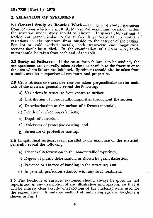
2.1 General Study or Routine Work - For general study, specimens from locations which are most likely to reveal maximum variation within the material under study should be chosen. In general, for castings, a section cut perpendicular to the surface is prepared as it reveals the variations in the structure from outside to the interior of the casting. For hot or cold worked metals, both transverse end longitudinal sections should be studied. In the examination of strip or wire, speci- mens should be taken from each end of the coils.
2.2 Study of Failures - If the cause for a failure is to be studied, the test specimens are generally taken as close as possible to the fracture or to the area where failure has initiated. Specimens should also be taken from a sound area for comparison of structures and properties.
2.3 Cross sections or transverse sections taken perpendicular to the main axis of the material generally reveal the following:
4
b) 4 4 4 f>
9)
Variations in structure from centre to surface,
Distribution of non-metallic impurities throughout the section,
Decarburization at the surface of a ferrous material,
Depth of surface imperfections,
Depth of corrosion,
Thickness of protective coating, and
Structure of protective coating.
2.4 Longitudinal sections, taken parallel to the main axis of the material, generally reveal the following:
a) Extent of deformation in the non-metallic impurities;
b) Degree of plastic deformation, as shown by grain distortion;
c) Presence or absence of banding in the structure; and
d) In general, pertection attained with any heat treatment.
2.5 The locations of surfaces examined should always be given in test reports and in any description of any illustrative micrographs, so that it will be entirely clear exactly what sections of the material were used for the examination. A suitable method of indicating surface locations is shown in Fig. 1.
4

IS : 7739 ( Part I ) - 1975
3. SIZE OF SPECIMENS
3-l The specimen to be polished for metallographic examination should generally be not more than 10 to 25 mm square, or approximately 10 to 25 mm in diameter if the material is round. The height -of the specimen should be such that it provides for convenient handling during polishing.
Spboi in Suggrsted Diagram Designation
Suggested Designation
: c D
E
Rolled surface Direction ofrolling Rolled edge Longitudinal ( or
lengthwise ) sec- tion parallel to rolled surface
Longitudinal sec- tion perpendicu- lar to rolled surface
c”
H
Transverse section Radial longitudinal
section Tangential longi-
tudinal section
Fro. 1 METHOD OF DESIGNATING LOCATION OF AREA SHOWN IN PHOTOMICROCRAPH
3.2 In the case of wire, strip and other small articles, where it may not be possible to secure specimens, having the dimensions given in 3.1, the specimens may be suitably mounted for convtnient handling ( see 5 ).
5

IS : 7739 ( Part I ) - 1975
4. CUTTING OF SPECIMENS
4.1 The sl~cimen may be cut by a hacksaw, bandsaw or a cutting off wheel. In the case of hard and brittle materials the specimen may be n,otched and fractured. Flame cutting may be used in order to obtain suitable specimens from large sections.
4.2 In cutting the metallographic specimen from the main body of the material, care shall be exercised to avoid affecting the structure of the luetal. The types of injury to the structure during cutting and the mrthods employed for removal of the injured surfaces are:
;I) I)ragging of the metal by the cutting edge. Lubrication during c-uttin,g tends to keep dragging at a minimum.
I)) Flame cutting completely alters the structure of the metal at the Hame cut edge. If flame cutting is necessary to remove the sl &men, it should be cut sufficiently large so that it may be recut to the proper size by some other method.
c) Heating of hardened structure during cutting, thus tempering the material. This heating may be minimized by keeping the work cooled by water during cutting.
d) Where grinding or spark-machining techniques have been used to remove specimens from hard materials, care shall be taken to fully remove the affected layers by prolonged grinding on the coarse paper.
5. MOUNTING OF SPECIMENS
5.1 Specimens that are too small to be handled readily during polishing should be mounted to ensure a surface satisfactory for microscopical study. The various methods that may be used are discussed in 5.1.1 to 5.1.4.
5.1.1 Mechanical Mountings - Strip and sheet samples are frequently mounted by binding several specimens into a pack held together by two end pieces and two bolts. These end pieces should preferably be of the same hardness as the specimens being mounted, since rounding off the edges of the polished section is often due to the difference in hardness of the specimens and the end holders. The specimens should be tightly bound together to prevent excessive absorption and subsequent exudation of polishing liquids and etchants. Pores may be filled by immersing the pack in molten paraffin; separating the sheets with dense blotting paper may also eliminate this exudation ( the blotting paper may become impregnated with abrasive, however, and make polishing difficult ). Exudation shall be particularly guarded against if the etchant may attack the lens system of the microscope. The sheets to be examined are frequently ,alternatetl with ‘ filler ’ sheets of a softer alloy in order to secure a more

IS : 7739 ( Part I ) - 1975
compact specimen and to preserve surface irregularities, but the ‘ filler ’ material shall not react electrolytically with the specimen during etching. Steel sheets mounted with alternate ’ filler ’ strips of copper may be retched in the holder since the usual etchant for the steel will not attack the copper. Longitudinal sections of round wire may be mounted by the same method of holders except that only one wire may be mounted in one holder.
5.1.2 Electroplated Mountings - Small wires, odd shapes, fractures, or specimens of which the edges are to be examined are frequently electro- plated before mounting to avoid tearing or rounding off during subsequent polishing. These electroplated specimens are invariably mounted by some other process after plating. Ferrous metals are usually copper plated for this purpose. A flash coat in a copper cyanide bath ( Note 1 ) is first applied, followed by plating in a copper sulphate bath ( Note 2 ). Some laboratories frequently apply the entire coat using the cyanide bath. The precious metals are frequently plated with nickel, gold, or silver, while fractures of many non-ferrous metals are conveniently plated with silver. The plating metal should be somewhat softer than the specimen to avoid differential polishing of the material, that may mask the edge, and should not react electrolytically with the base metal of the specimen.
NOTE 1 - For the copper cyanide bath use 22.5 g of cuprous cyanide, 34 g of sodium cyanide and I5 g of sodium carbonate in a litre of water; current density of O-2 A/dmz.
NOTE 2- For the copper sulphate bath use 250 g of copper sulphate crystals and 75 g of concentrated sulphuric acid ( sp gr 1.84 ) in a litre of water; current density of 2 to 4 A/dm2.
5.1.3’ Cast and Cement-like Mountings - Some types of specimens are frequently placed in a mounting ring and a mounting medium is cast around them. In selecting the mounting medium, some consideration shall be given to its resistance to attack by the etchants to be used and the effect of the mounting on the specimen in regard to electrolytic attack at the point of contact. Likewise, a thermal effect due to the temperature of the melting point of the mounting shall be given consideration, so that no change occurs in the structure of the specimen to be examined. In general, this classification of mounting may be divided into two fields; fusible metal alloys which are cast to shape, and cement-like mixture which harden to shape.
5.1.3.1 Ferrous metals and alloys are occasionally mounted in solder of 50 percent lead and 50 percent tin. An alloy of 52’5 percent bismuth, 31.5 percent lead, and 16 percent tin ( melting point 95 to 98°C ) is used in some laboratories. Cadmium-zinc eutectic ( 82’5 percent cadmium, 17.5 percent zinc, melting point 264.5% ) has been found a useful mount- ing material for zinc castings, since it possesses the same polishing and etching characteristics as zinc. The temperature of the alloy should be kept below 300°C since cadmium oxide fumes are very poisonous.

1S : 7739 ( Part I ) - 1975
Sulphur is used as a mounting medium as it has a low melting point ( 119°C ) and resists attack by most cold-etching reagents. It may some- times cause pitting in steel samples and occasionally tends to tarnish copper alloys.
5.1.3.2 Similar mounting may be done by using plaster of Paris, sealing wax, iron-ammonium chloride cements, litharge-glycerin cement, and some dental cements, especially for non-ferrous materials, such as gold, platinum, other precious metals, and iow melting-point alloys.
5.1.4 Tkermosetting and Thermojktic Materials - Modern plastics of either the thermosetting or thermoplastic types form a class of metallqgraphic mounting materials more or less related to the cast or cement-like materials. In general, they are employed for the same reasons and in much the same manner. It should be noted, however, that specimens of hardened alloys may be softened by mounting in this way, since heating temperatures between 140 and 160°C is required.
5.1i4.1 The thermosetting materials undergo a chemical reaction on application of heat and pressure during the moulding process which-causes them to set up into a more or less permanent state that cannot further be changed by temperatures up to those which cause the material to char. The thermoplastic resins, on the other hand, will flow each time that the proper combination of heat and pressure is applied. This difference between the materials is important and should -be recognized. There is little, if any, choice between the materials in so far as their ability to be moulded adequately is concerned.
5.1.4.2 The thermosetting resins are usually of the formaldehyde type, whereas the thermoplastic resins comprise the polystyrenes, methacrylates, cellulose-base materials, etc.
5.1.4.3 ‘Because of the fundamental differences in the two classes of materials, the thermoplastic resins are cooled to approximately 75 to 80°C before removal from the mould whereas the thermosetting resins may be removed from the mould as soon as the resin has ‘ set up ‘.
5.1.4.4 Comparing these materials from’ the standpoint of chemical resistance, it is found that the thermosetting resins dare decomposed by strong oxidizing acids and strong alkalis but are resistant to other materials, while the thermoplastic resins may somewhat be attacked by strong acids and alkalis and- are usually very soluble in organic solvents but are other- wise resistant.
5.1.4.5 The nominal Brine11 hardness values of the moulding materiais, using a IO-mm ball and 500 kg load, are as follows:
8
c

IS : 7739 ( Part I ) - 1975
Maulding Material Thermoplastic
Polystyrene Methyl methacrylate :
Soft
Hard
i3ermasetting
Aniline formaldehyde
Phenol-formaldehyde ( Bakelite )
.Nominal Brine11 Hardness
19-22
17-20 27
30
42
5.1.4.6 With the exception of the aniline formaldehyde, which is more resistant to abrasion than its hardness would indicate, the remaining materials given in 5.1.4.5 withstand polishing in about the same order as of their hardnesses.
5.1.4.7 Keeping in mind the nature of the thermoplastic resins, it is evident that rushing the polishing operation to the point where the sample gets hot may cause considerable flow in the mounting, a circumstance not encountered with the tliermosetting types. This may account for the more rapid polishing away’ and rounding of? encountered in the thermoplastic materials. Theedges of steel specimens are not very well supported by mounts of this nature, and the use of a harder material or a steel clamp is preferable when sections are to be examined at the extreme edge.
5.1.4.8 The use of transparent mounting materials, which are thermoplastics, seems justifiable only in those instances where sectioning and polishing to an exact position are necessary and the progress of the work has to be observed.
5.1.4.9 The equipment necessary for forming plastic mountings may be made up from a hydraulic auto jack mounted between foot and header plates with a third plate on the head of the jack to serve as the lower platen.
5.1.4.10 The heating may be accomplished by heated platens or by surrounding the mould with a small electric furnace. When thermoplastics are used, cooling methods shall also be utilized. The best combination is obtaiined by using steam heat and, where necessary, water cooling.
5.1.4.11 Several precautions should be observed if good results are to be obtained, for it is essential that all the material be heated uniformly to the proper temperature, this being accurately checked by thermo- meters or pyrometers properly located, and that the proper pressures be utilized.
9

IS 2 7739 ( Part I ) - 1975
6. CLEANING, GRINDING AND POLISHING OF SPECIMENS
6.1 Cleanliness during polishing is essential. All grease and oils should be removed by some suitable organic solvent. Any coating metal which will interfere with the subsequent etching of the base metal should be removed before polishing. Rusted fractures may be cleaned with a diluted solution of ammonium citrate or phosphoric acid. In studying the underlying steel in a galvanized specimen, the zinc coating shall be removed before polishing. The zinc may be removed by solution in cold nitric acid ( HNOs ) or in diluted sulphuric acid ( H,SOa ). The HNOs method requires care to prevent overheating, since large samples will generate considerable heat. By placing the cleaning container in cold water during the stripping of the zinc, the underlying steel will not be attacked after the removal of zinc.
6.2 The surface of the specimen is first made plane by means of a file or by rough grinding on an abrasive wheel or an emery belt. The specimen should be kept cool by frequently dipping it in water during grinding operations in order to avoid any changes in the structure of the metal at the surface. In non-ferrous metals further precautions may be necessary.
6.2.1 The specimens are further ground ( wet or dry ) on emery/silicon carbide papers or abrasive wheels/discs with successively finer grinding media, until a suitable surface is obtained for polishing. Usually, final grinding is done on abrasive materials with 400 to 600 grits. ( For details of grit numbers, see IS : 715-1966* and IS : 2832-19647 ). A comparative chart of grit numbers and trade designations is given in Appendix A.
6.2.2 The usual practice is to rotate the specimen by 90” when changing from one grade of abrasive to another. The specimen is gradually rotated while polishing on abrasive wheels/discs. A thorough washing of the specimen while changing, from one grade of abrasive to the next one is recommended. It is also desirable to ensure that scratches from the previous abrasive are eliminated while polishing on the next one- the exception being the first coarsest abrasive in which case care should be taken to fully remove the scratches from the cutting operation.
6.2.3 The specimens may also be prepared by electropolishing. For details about this process reference may be made to Part II of this code.
*Specification for coated abrasives, glue bond ( second ravision ). tSpccification for waterproof silicon carbide paper.
10

APPENDIX A
( Clause 6.2. I )
GOMPARATWE CirART OF GRIT NUMBERS (APPROXIMATE) OF ABRASIVE GRAINS
Alumirrium Oxide Flint Ch Corundum Emery Trade Siliron and 7-B-L -w7 r-_--A--_7 __h___T ,-..-.--h--~ Designation
Gnrnct IS C.rit B* Grade IS Grit BS Grade IS Grit BS Grade IS Gtir BS Grade ~_-,.A-__ Number Number sumher Number Number Number Number I\‘umber IS Grit B’, Grade
Number Number
14 1-i
16 16
24 24
30 30
36 36
40 46
50 54
60 60
80 80
loo IO0
120 120
150 150
180 180
220 220
- -
24
30
36
40
50
60
80
100
120
150
180
-
- - - - -_ - - -
3 24 3 24
2f 30 24 30
2 36 - 36
1) 40 S2 ‘IO
I 50 M2 50
t 68 - GO
- 80 - 80
0 100 F2 100
00 121) It 120
- 150 1 150
- 180 0 180 - - -
- - - -
- 24
- 30
- 36
- 40
-- 50
- 60 ‘4 - 80 1
- 108 F
-- 120 FF
- 150 -
- 180 0
- - - -
3
26 2
-
Extra Coarse
Extra Coarse
Coarse
Coarse
Medium Coarse
Medium
Medium
Medium Fine
Fine W
Fine ; Extra Fine
: - c(
Y
NOTE - Grits 240 and linrr conw under the sub-sieve range and as limits for these cannot be set on common silk test ’ sieves, the grain sizes shah conform to general commercial grading, and it is recommended that thesedimentation 5t process be adopted for their analysis. J

BUREAU OF INDIAN STANDARDS
Headquarters: Manak Bhavan, 9 Bahadur Shah Zafar Marg, NEW DELHI 110002 Telephones: 323 0131,323 3375,323 9402 Fax : 91 11 3234062,Ql 11 3239399, 91 11 3239382
Telegrams : Manaksanstha (Common to all Offices)
Central Laboratory : Telephone
Plot No. 20/9, Site IV, Sahibabad Industrial Area, Sahibabad 201010 8-77 00 32
Regional Offices:
Central : Manak Bhavan, 9 Bahadur Shah Zafar Marg, NEW DELHI 110002 823 78 17
*Eastern : l/14 CIT Scheme VII M, V.I.P. Road, Maniktola, CALCUTTA 70005’4 i 337 86 62
Northern : SC0 335-336, Sector 34-A, CHANDIGARH 180022 60 38 43
Southern : C.I.T. Campus, IV Cross Road, CHENNAI 600113 235 23 15
fWestern : Manakalaya, EQ, Behind Marol Telephone Exchange, Andheri (East), 832 92 95 MUMBAI 400093
Branch Offices::
‘Pushpak’, Nurmohamed Shaikh Marg, Khanpur, AHMEDABAD 380001 550 1348
$Peenya Industrial Area, 1 st Stage, Bangalore-Tumkur Road, 839 49 55 BANGALORE 560058
Gangotri Complex, 5th Floor, Bhadbhada Road, T.T. Nagar, BHOPAL 462003 55 40 21
Plot No. 62-63, Unit VI, Ganga Nagar, BHUBANESHWAR 751001 40 36 27
Kalaikathir Buildings, 670 Avinashi Road, COIMBATORE 641037 21 01 41
Plot No. 43, Sector 16 A, Mathura Road, FARIDABAD 121001 8-28 88 01
Savitri domplex, 116 G.T. Road, GHAZIABAD 201001 8;71 1996
53/5 Ward No.29, R.G. Barua Road, 5th By-tane, GUWAHATI 781003 541137
5-8-56C, L.N. Gupta Marg, Nampally Station Road, HYDERABAD 500001 201083
E-52, Ciiitaranjan Marg, C- Scheme, JAIPUR 302001 37 29 25
117/418 B, Sarvodaya Nagar, KANPUR 208005 21 88 76
Seth Bhawan, 2nd Floor, Behind Leela Cinema, Naval Kishore Road, 23 89 23 LUCKNOW 226001
NIT Building, Second Floor, Gokulpat Market, NAGPUR 440010 52 51 71
Patliputra Industrial Estate, PATNA 800013 26 23 05
Institution of Engineers (India) Building 1332 Shivaji Nagar, PUNE 411005 32 36 35
T.C. No. 14/l 421, University P. 0. Palayem, THIRUVANANTHAPURAM 695034 621 17
*Sales office is at 5 Chowringhee Approach, P.O. Princep Street, 271085 CALCUTTA 700072
tSales office is at Novelty Chambers, Grant Road, MUMBAI 400007 309 85 28
*Sales Office is at ‘F’ Block, Unity Building, Narashimaraja Square, 222 39 71 BANGALORE 560002
Reprography Unit, BIS, New Delhi, India