is-7098 pt -1. (2)
TRANSCRIPT

7/27/2019 IS-7098 Pt -1. (2)
http://slidepdf.com/reader/full/is-7098-pt-1-2 1/17
IS:7098(Part1)-1988
I ndian St andard
SPECIFICATION FORCROSSLINKED POLYETHYLENE INSULATED
PVC SHEATHED CABLESPART 1 FOR WORKING’VOLTAGES UP TO AND INCLUDING 1 100 VOLTS
( Fi rst Revi si on
First Reprint SEPTJZMBER1991:
UDC 621~315~221%678~742-2
0 Copyright 1990
BUREAU OF INDIAN STANDARDSMANAK BHAVAN, 9 BAHADUR SHAH ZAFAR MARG
NEW DELHI 110002
GrS Jm 1998
( Reaffirmed 1999 )

7/27/2019 IS-7098 Pt -1. (2)
http://slidepdf.com/reader/full/is-7098-pt-1-2 2/17
I ndian St andard
IS:7O!M(Partl)-1988
SPECIFICATION FORCROSSLINKED POLYETHYLENE INSULATED
PVC SHEATHED CABLESPART 1 FOR WORKING VOLTAGES UP TO AND INCLUDlhlG 1 100 VOLTS
( Fi rst Rev i si on
0. FOREWORD
This Indian Standard (Part 1) (First Revision)adopted by the Bureau of Indian Standards
22 December 1988, after the draft finalized byPower Cables Sectional Committee had been
by the Electrotechnical Division Council.
This standard was first published in 1977.has been undertaken to align it with
international practices and to take into accountexperience gained during this pericd in the
of these types of cable in the country.
Particular attention is drawn to the limitationsthe short circuit ratings of the types of cable
this standard owing to the absencethe metallic sheath and the possible loss of the
contact between the strands of the armoura result of corrosion or the presence of
between them. A separate standardshort circuit ratings of these
is under
Attention is alsocurrent rating of
ureuarat ion.1 -
value in this standard.drawn to the fact thatthe types of cable Rules for rounding off numerical values ( revised).
SECTION 1
SCOPE
covered by this standard are different from thoseof paper insulated metal sheathed cables. This
standard does not include any data on the currentratings but information on this aspect will becovered in a separate Indian Standard later. Inthe meanwhile, users are advised to consult themanufacturers for information on this aspect.
0.5 In the preparation of this standard, assistarce
has been derived from IEC Publication 502 (1983)‘Extruded solid dielectric insulated power cablesfor rated voltage from 1 kV to 30 kV’, issued bythe International Electrotechnical Commission.
0.6 For the purpose of deciding whether a parti-cular requirement of this standard is complied
with, the final ‘value, observed or calculated.expressing the result of a test, shall be roundedoff in accordance with IS : 2-l-960*. The numberof significant places retained in the rounded offvalue should be the same as that of the specified
GENERAL
This standard (Part 1) covers the requirementsboth armoured and unarmoured single, twin,
and multi-core crosslinked polyethyleneand PVC sheathed cables for
supply and control purposes.
The cables covered in this standard are,for use on ac single phase or three phaseor unearthed) systems for rated voltages
to and including 1 100 V. These cables mayused on dc systems for rated voltages up to
1 500 V to earth.
NOTE The cables conforming to this standard mayoperated continuously at a power frequency voltagepercent higher than rated voltage.
1.3 Armoured cables specified in this standardare suitable for use in mines also. However, for
such cables, additional requirements have beenincluded, wherever necessary (3.1.1, 13.5 and17.2 ) .
1.4 These cables are suitable for use where com-bination of ambient temperature and temperaturerise due to load results in conductor temperaturenot exceeding 90°C under normal operation and250°C under short circuit condition.
2. TERMINOLOGY
2.0 For the purpose of this standard the followingdefinitions, in addition to those given in IS : 1885
(Part 32 ) - 1971* shall apply.*Electrotechnical vocabulary: Part 32 Cables, conductors
and accessories for electricity supply.

7/27/2019 IS-7098 Pt -1. (2)
http://slidepdf.com/reader/full/is-7098-pt-1-2 3/17
IS : 7098 ( Part 1) - 1988
2.1 Rouline Tests -Tests made by the manu-facturer on all finished cable lengths to demons-trate the integrity of the cable.
2.2 Type Test -Tests required to be madebefore supply on a general commercial basis ona type of cable in order to demonstrate satisfactory
performance characteristics to meet the intendedapplication.
NOTE These tests are of such a nature that afterthey have been made, they need not be repeated unlesschanges are made in the cable materials or design whichmight change the performance characteristics.
2.3 Acceptance Tests -Tests carried out onsamples taken from a lot for the purpose of accep-tance of the lot.
2.4 Optional Tests -Special tests to be carriedout, when required, by agreement between thepurchaser and the supplier.
2.5 Earthed System -An electric system whichfulfills any of the following conditions:
a)
b)
c)
The neutral-point or the mid-point connec-tion is earthed in such a mannet that, evenunder fault conditions, the maximumvoltage that can occur between any conduc-tor and the earth does not exceed 80 percentdf the nominal system voltage;
The neutral-point or the mid-point connec-tion is not earthed but a protective deviceis installed which automatically cuts out
any part of the system which accidentlybecomes earthed: or
In case of ac systems only, the neutral-point is earthed through an arc suppressioncoil with arradgement for isolation within1 h of occurrence of the fault for thenon-radial field -cables afid within 8 h forradial cables, provided that the total of suchperiods in a year does not exceed 125 h.
2.6 Unearthed System -- An electric system whichdoes not fulfil the requirement of the earthedsystem (SCP2.5). _
SECTIOI’U 2 MATERIALS
3. CONDUCTOR
3.1 The conductor shall be composed ofcopper or aluminium wires complyingIS : 8130-19s4*.
plainwith
3.1.1 Mining cables to be used in gassyshall be of copper conductor only.
4. INSULATION
mines 6. ARMOURING
4.1 The insulation shall be of crosslinked
_POY
*Specitication for conductors for Insulated electric
cables and flexible cords (fi rst ,revision ).
ethylene conforming to the requirements givenin Table 1.
TARLE 1 PROPERTIES OF XLPE INSULATION(Clause4.1 )
SL No. PROPERTY REQUIREMENT
(1) (2) (3)
i) Tensile strength 12.5 N/mmz, Mir
ii) Elongation at break 2OQpercent, Min
iii) Ageing in air oven
a) Treatment : TemperatureDuration
6) Tensile strength variation
c) Elongation variation
iv) Hot set
13513°CI days
+ 25 percent, Max
&25 percent, Max
a) Treatment : Temperature 20013°CTime under load 15 minutesMechanical stress 20 N/cm2
b) Elongation under load 175 percent, Maxc) Permanent elongation (set) 15 percent, Max
after cooling
v) Shrinkage
a) Treatment : TemperatureDuration
b) Shrinkage
vi) Water absorption (gravimetric)
a) Treatment : TemperatureDuration
.b) Water absorbed
vii) Volume resistivity:
a) at 27°C
b) at 90°C
130f3”C1 hour
4 percent, Max
zl::
1 mg/cm*,Max
1 x;,r ohm-cm,
I xi,y ohm-cm,
5. FILLER AND INNER SHEATH
5.1 The fillers and, inner sheath shall be of thefOllo+ing:
a) Vulcanized or unvulcanized rubber, or
b) Themroplastic materials.
5.2 Vulcanized or unvulcanized rubber or ther-moplastic material used for inner sheath shall not
be harder than XLPE and PVC used for insulationand outer sheath respectively. Fillers and Innersheath materials shall be so chosen as to be com-patible with the temperature ratings of the cableand shall have no deleterious effect on any othercomponent of the cable.
6.1 Armouring shall be of the following:
a) Galvanized round steel wire, or
b) Galvanized steel strip, or
C) Any metallic non-magnetic wire/strip.
2

7/27/2019 IS-7098 Pt -1. (2)
http://slidepdf.com/reader/full/is-7098-pt-1-2 4/17
IS :‘7098 ( Part 1) - 1984
6.2 The galvanized steel wires/strips shall coinplywith the requirements of IS : 3975-1979*. Therequirements of non-magnetic material shall be asagreed to between the purchaser and the supplier.
7. OUTER SHEATH
7.1 The outer sheath shall be of polyvinylchloride (PVC) compound conforming to therequirements of type ST 2 compound of IS :5831-19847.
SECTION 3 CONSTRUCTION
8. CONDUCTOR
8.1 The constructionas follows:
of the conductor shall be
Nominal Cross-SectionC____h-
Copper Aluminium7mm% mm2
- 1.5
Solid/Stranded
Solid
Flexibility Class
8:4%3& )
1
1.5-6 2.5 - 19 Solid/Stranded 1 for solid2 for stranded
10 and 16 and Stranded 2above above
8.2 A protective barrier may be applied betweenthe conductor and insulation. Such barriers,when used, shall be compatible with insulating‘material and suitable for the operating tempera-ture of the cable.
8.3. Cables with reduced neutrai conductor shallhave sizes as given in Table 2.
TABLE 2 CROSS SECTIONAL AREA OF REDUCEDNEUTRAL CONDUCTORS
NOMINAL ROSS CROSS ECTIONALREASECTIONALREA OF OF REDUCEDNEUTRALMAIN CONDUCTOR @NoUcn>R
(1) (2)
mm8 mm’
25
z;::25
;: :;
:zz z185
Z%1;;150
400 185500630 %
*Specification for mild steel wires, strips and tapes for(fir st revision ).
tspecification for PVC insulation and sheath of electricfir st revision ).
SSpecification for conductors for insulated electric cables(fir st revision ).
9. INSULATION
9.1 The conductor (with protective barrier. wnere-ever applied) shall be provided with crosslinkedpolyethylene insulation applied by extrusicn.
9.2 Thickness of Insulation - The average
thickness of insulation shall be not less thanthe nominal value (ti) specified in Table 3.
TABLE 3 THICKNESS OF INSULATION
NZt:FLCONDIJCTCIR
(1)
mma
;:;
46
::2535
50
;:120
:g240
300
zz
630800
1000
( Clauses 9.2 and 9.3 )
NOMINAL THICKNESSOF INSULATION
(ti)r_-----*_----_-~
S~inoJ 30e Single CoreUnarmoured and
Cables Multi-core Cables
(2) (3)
mm mm
1:; 0.7
8:;
1.0 0.7
1.0 0.7
::; X:9’
1.2 0.9
1.31.4 ::y
::; ::;
::9’ ::;:
2.0 1.7
2”:: 1.8
2:: 2.4:;
3.1 2.63.3 2.8
9.3 Tolerance on Thickness of Insulation - Thesmallest of-measured values of thickness of insulartion shall not fall below the nominal value (ri)specified in Table 3 by inore than 0.1 mm + O-1
Cti)*
9.4 Application of Insulation - The insulationshall be so applied that it fits closely on the conduc-tor (or barrier if any) and it shall be possible toremove it without damaging the conductor.
10. CORE IDENTIFICATION
10.1 Cores shall be identified as specified below:
a) Coloured strip applied on the core (seeNote l), or
b) Colouring of XLPE insulation as follows:
1 Core : Red, black, yellow, blue ornatural:
2 Core’ : Red and black;
3 Core : Red, yellow and blue;
4 Core : Red, yellow, blue and black;
3

7/27/2019 IS-7098 Pt -1. (2)
http://slidepdf.com/reader/full/is-7098-pt-1-2 5/17
IS:7@8(Partl)-1988
5 Core : Red, yellow, blue, black andpy; -
6 C$eFd : Two apjacent cores (c.ountingand direction core) In eachlayer, blue and yellow, re-maining cores, grey; or
c) By numerals either by applying numberedstrips or b printing on the cores as follows(see Note g):
2 Core : 0, 1
3 Core : 0, 1, 2. 3
4 Core : 0, 1,2and3
NOTE 1 - For identification by using coloured strips,red; yellow and blue colours shall be used to identifythe phase conductors, and black to identify reducedneutral conductor.
NOTE 2 - Identification by numerals is applicableup to 4 core cables. For control cables, numerals 0 and
1 shall be adopted for counting core and direction corerespectively; remaining cores shall not be numbered.
10.2 For reduced neutral conductors, the coreshall be black.
10.3 For cables having more than 5 cores, asan alternate to the provisions of 10.1 the coreidentification may be done by numbers. 1~1 thatcase the insulation of cores shall be of the samecolour and numbered sequentially, starting bynum%F I in the inner layer. The numbers shallbe prlnted in Hindu-Arabx numerals on the outersurface of the cores. Al1 the numbers shall beof the same colour, which shall contrast with the
colour of the insulation. The numerals shall belegible.
10.4 For reduced neutral conductors, the coreshall have ‘0’ number.
11. LAYING UP OF CORES
11.1 In twin, three and multi-core cables, thecores shall be laid up together with a suitable lay,the outermost layer shall have right-hand layand the successive layer shall be laid with oppositelay. Where necessary, the interstices shall befilled with non-hygroscopic material.
11.2 The recommended plan for lay-up of multi-cores up to 100 shall be in accordance with Table 4.
, 12. INNER SHEATH (COMMON COVtYtING)
12.1 The laid up cores shall be provided withan inner sheath applied either by extrusion or bywrapping. It shall be ensured that it is as circularas possible.
12.2 The inner sheath shall be SO applied that itfits closely on the laid up cores and it shall bepossible to remove it without damage to theinsulation.
TABLE 4 LAY-UP OF CORES( Clalcse 11.2)
(1)No. OF%t~s
i9
10
3132
ii35
3617
414243
4*:
4647484950
51
siz:55
56
FOR CABLES
(2)LAY-UP
6
::f
;::
;:f
3-104-10S-10
5-11 ’5-12o-6-12I-6-12
1-7-121-7-132-7-132-7-13
%‘:_
3-9-143-9-153-9-164-10-l 54-10-16
4-10-175-11-165-11-17
:-:z:-
;-:6-;-t;
1:6-12:r91-6-13-19I-7-13-19
I -7-13-U)2-8-13-192-8-M-192-8-14-U)2-8-14-21
3-9-14-203-9-15-U)3-9-15-213-9-l 5-223-9-16-22
4-10-16-21
4-10-16-224-10-16-234-10-17-234-11-17-23
5-l 1-17-235-l l-17-245-l l-18-245-12-18-24O-6-12-18-24
I-6-12-18-24l-6-12-18-24l-7-12-18-25l-7-13-18-25l-7-13-19-25
(Continmi~
4

7/27/2019 IS-7098 Pt -1. (2)
http://slidepdf.com/reader/full/is-7098-pt-1-2 6/17
TABLE 4 LAY’.UP OF CORES FOR CABLES-Conrd
No. OF Cows LAY-UP
66 1-7-13-19-26
z2-8-13-19-2s2-8-14-19-25
69 2-8-14-20.2570 2-8-14-20-26
z 2-8-14-20-27
73 ;$;yg. . .
74 3-9-l S-21 2675 3-9-15-21-27
3-9-15-21-283-9-15-22284-10-15-21-284-10-16-22-274-10-16-22-28
::. 4-10-16-23-2910-16-22-29
ii 4.10-17-23-29-11-17-23-28-11-17-23-29
if 5-11-17-24-30-l 1-17-23-30
:: 5-11-18-24-30O-6-11-18-24-30
90 0.6.1218.%-30
;; 1-6-12-18-24-30.6-12-18-24-31
;: 1-6-12-18-25-31-6-12-19-25-3195 l-6-13-19-25-31
9’4I-7-13-19-25-311-7-13-19-26-31
;t 2-8-13-19-25-31-8-14-19-25-31100 2-8-14-20-25-31
NOTE 1 - The figures indicate the number of coresin each successive ayer; for example, S-11-18means,.5core in first, 11 cores in the second and 18 in the thirdlayer, etc.
NOTE 2 - This table is for guidance only.
12.3 Thickness of Inner Sheath -The thicknessof inner sheath (common covering) shall be asgiven in Table 5. Single core cables shall have
110 inner sheath.
TABLE 5 THICKNESS OF INNER SHEATH
CALCULATEDDIAMETER THICKNESS OF
OVER LAID-UP COKES INNER SHEATH
[REF IS : 10462 PART 1) - 1983*] (Mill)
r----_*_. ---~
Over Up to andIncluding
(1) (2) (3)
mm mm mm
s2.5 0.335
35 45 8.1:
45 55 0.6
55 - 0.7
/ *Fictitious calculation method for determination ofdimensions of protective coverings of cables : Part 1
IS:7098(Partl)-1988
12.3.1 When one or more layers of proofedor plastic tape are applied over the laid up coresas a binder, the thickness of such tapes shall notbe construed as part of the extruded inner sheath.
13. ARMOURING
13.1 Application
13.1.1 Armouring shall be applied over theinsulation in case of single core cables and overthe inner sheath in case of twin, three and multi-core cables.
13.1.2 The armour wires/strips shall be appliedas closely as practicable.
13.1.3 The direction of lay of the armourshall be left hand. For double wire/stripamoured cables, this requirement shall apply to
the inner layer of wires/strips. The outer layershall, except in special cases, be applied in thereverse direction to the inner layer, and there shallbe a separator of suitable non-hygroscopic materialsuch as plastic tape, bitumenized cotton tape,bitumenized hessian tape, rubber tape or proofedtape between the inner and other layers of armourwires/strips.
13.1.4 A binder tape may be provided onthe armour.
13.2 Type of Armour-Where the calculateddiameter below armouring does not exceed 13 mm,
the armour shall consist of galvanized roundsteel wires.
Where the calculated diameter below thearmouring is greater than 13 mm, the armourshall consist of either galvanized round steelwires or galvanized steel strips.
NOTE - It may be desirable for single core cablesintended for use on ac systems to be armoured with non-magnetic material. In such cases, special agreementshall be made between the purchaser and the manufac-turer.
13.3 Dimensions -- The dimensions of galvanized
steel wires or strips shall be as specified in Table 6.13.4 J oints -The joints in armour wire orstrip shall be made by brazing or welding and thesurface irregularities shall be removed. A jointin any wire/strip shall bc at least 300 mm fromthe nearest joint in any other armour/wire/stripin the completed cable.
13.5 Resistance
13.5.1 If specified by the purcnaser, the dcresistance of the galvanized steel wire strip armourshall bc measured. The result, when corrected
to 20°C shall comply with the appropriate valuesgiven in Table 7.
13.5.2 1.n case of cable for the use in mines,

7/27/2019 IS-7098 Pt -1. (2)
http://slidepdf.com/reader/full/is-7098-pt-1-2 7/17
IS :7098(P8rtl)-1988
TABLE 6 DIMENSIONS OF ARMOUR ROUND WIRESthe conductor as specified in IS : 8130-1984* by
AND STRIPSmore than 33 percent. To satisfy this, substitution
(Cla r 4se 13.3 ) of galvanized tires/strips in armouring by required
CALCULATED DIAMETER NOMINAL NOMINAL numbe; of tinned copper wires/strips is permissible.UNDERAI&XX [REF THICKNESS DIAMETERIS : lol~;3$~ 1 ) - OFSTEEL
STRIPo~gz 14. OUTER SHEATH
----,
Over Up to and
;1,
Including
(2)mm mm
(a) For all diameter inexcess of 13
(3) (4)mm mm
0.8
14.1 The outer sheath shall be applied by extru-sion. It shall be applied:
a) Over the insulation in case of unarmouredsingle core cables;
b) Over the inner sheath in case of unarmouredtwin, three and multi-core cables; and
c) Over the armouring in case of armouredcables.
14.2 Colour or outer sheath shall be black orany other colour as agreed to between the pur-shaser and the supplier.
*Specification for conductors for insulated electric cablesand flexible cords ( f i r s t rev i s i on ) .
(b) G ” 1.401.60~
z40 0.8 2.0055 1.4 2.50
;:70
::; _3.15
- 4.00NOTE (a) and (b) indicate two methods of practice
in the application of armouring.
*Fictitious calculation method for determination of
dimensions of protective coverings of cables : Part 1 Elas-tomeric and thermoplastic insulated cables.
TABLE 7 ARMOUR RESISTANCE OF CABLES
[Clauses 13.5.1 a n d 15.4 (c)]
MAXIMUM DC RESIWANCE F ARMOUROF CABLSAT 20°COMINALAREA OF
CoNouc~0~~---------- AC-
Two Core----------3
Three Core Four Core Four Core with~_-.--*-----_~ Reduced Neutral
Round Strip~-h-.----7 ,--h----7Round Strip Round Strip C_--A---,
wire C---*---T wire r__--h_-~ wire ,--~---5 Round4.0:; 6.1~ 4 .(j X.’~ 6.1~ 4*0x 6.1x wire
Strip’----*--.-~,4.0x
0.8mm
(12)
ohmIkm
(11)
-
-
-
--
3.90
3.60
3.28
2.71,
2.48
2,34
2.10
1.89
1.64
1.52
1.28
1.19
1.03
0.8 1.4 0.8 1.4 0.8 1.4mm mm mm mm mm mm
6.1x1.4
E
ohm/km
-
-
-
-
-
-
-
-
-
-
-
-
1.03
0.905
0.836
0.710
0.662
0.571
(1)mm2
1.5
2.5
4
6
10
16
25
35
50
70
95
120
150
185
240
300
400
500
630
(2)ohm:’km
6.71
6.07
5.45
4.91
4.25
3.57
3 .oo
2.88
2.47
2.15
1 ‘53
1.38
1.26
1.14
0.791
0.726
0.627
0.421
0.376
(3) (4) (5)
ohm/km
6.35
5.73
5.14
-4.633.99
2.89
2.68
2.522.20
1.49
1.31
1.17
1.05
0.767
0.675
0.619
0.428
0.379
0,264
(6).Ohlll:'
km
(7) (8)ohm/
km
5.82
5.24
4.69
4.21
3.62
2.62
2.29
2.12
1.93
1.24
1.12
I .Ol
0.737
0.652
0.590
0.409
0.377
0.245
0.214
(9) (10)ohm/ ohm/
km kmohm/
kmm km km
-
-
-
2.36
2.18
1.99
1.29
1.18
1.12
1 .Ol
0.715
0.625
0.577
0.384
0.358
0.241
-
--
4.32
3.78
3.49
3.18
2.59
2.34
2.11
1.95
1.72
1.55
1.37
1.26
1.04
0.910
-
4.77
4.42
4.16
3.64
3.12
2.75
2.45
2.19
2.03
1.78
1.63
1.43
1.27
1.13
-
4.95
4.754.07
3.55
3.21
2.88
2.63
2.38
2.09
1.92
1.65
1.41
1.25
---
1.07
0.944
0,855
0.755
0.697
0.581
0.507
1 .ll
0.976
0.896
0.791
0,701
0.627
1.14
1.05
0.908
0.778
0.695
NOTE I- The resistance of armour for single core cables has not been covered, since such cables are generally armouredwith non-magnetic materials ( see 13.2 ).
NOTE 2 - ‘The resistance of the armour may be measured at room temperature and corrected to 20°C by means of correc-tion factors given in IS: 10810 ( Part 42 ) - 1984 ‘Methods of test for cables: Part 42 Resistivity test of armourwires and strips and conductance test of armour (wires/strips)‘.
6
7/27/2019 IS-7098 Pt -1. (2)
http://slidepdf.com/reader/full/is-7098-pt-1-2 8/17
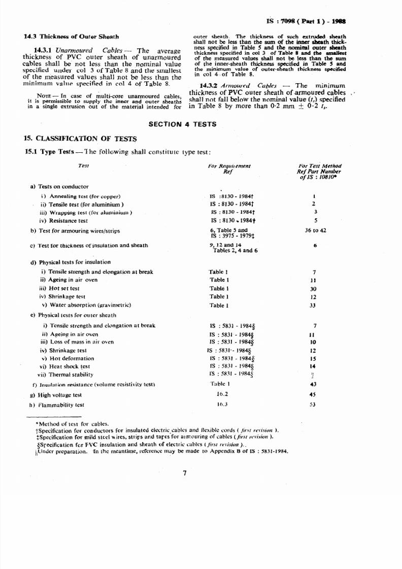
14.3 Thickness of Oufer Sheath
14.3.1 Unarmowed Cables -- The averagethickness of PVC outer sheath of unarmouredcables shall be not less than the nominal valuespecified under co1 3 of Table 8 and the smallestof the measured values shall not be less than theminimum value specified in co1 4 of Table 8.
NOTE In case of r&ti-core unarrnoured cablesit is permissible to supply the inner and outer sheath;in a single extrusion out of the material intended for
SECTION
15. CLASSIFICATION OF TESTS
outer sheath. The thickness of such extruded sheathshall not be less than the sum of the inner sbmth thick-ness specified in Table 5 and the nominal outer sheaththickness specified in co1 3 of Table 8 and the smallestof the measured values shall not be less than the sumof the inner-sheath thickness specified in Table 5 andthe minimum value of outer-sheath thickness specifiedin co1 4-.of Table 8.
14.3.2 Armoured Cables - The minimum
thickness of PVC outer sheath of .armoured cables I 0shall not fall below the nominal value (tJ specifiedin Table 8 by more than O-2 mm + 0.2 I,.
4 TESTS
15.1 Type Tests --‘Ihe following shall constitute type test:
Test
a) Tests on conductor
i ) Annealing test (for copper)
ii) Tensile test (for aluminium )
iii) Wrapping test (for aluminium )
iv) Resistance test
b) Test for armouring wires/strips
c) Test for thickness of insulation and sheath
d) Physical tests for insulation
i) Tensile strength and elongation at break
ii) Ageing in air oven
iii) Hot set test
iv) Shrinkage test
v) Water absorption (gravimetric)
e) Physical tests for outer sheath
i) Tensile strength and elongation at break
ii) AFeing in air oven
iii) Loss of mass in air oken
iv) Shrinkage test
v) Hot deformation
vi) Heat shock test
vii) Thermal stability
f) Jnsulation resistance (volume resistivity test)
g) High voltage test
h) Flammability test
*Method of test for cables.
For Requir emem
Ref
IS :8130 - 19847
IS : 8130 - 1984t
ZS : 8130 - 1984t
IS :8130.1984+
6, Table 5 andrs : 3975 - 1979$
9,12 and 14Tables 2,4 and 6
Table 1
Table 1
Table 1
Table 1
Table 1
IS : 5831 - 19849
IS : 5831 - 19845
IS : 5831 - 19845
IS : 5831.- 1984s
I’S : 5831 - 1984$
I’S : 5831 19843
I’s : 5831 1984s
Table 1
16.2
16.3
For Tess’ MethodRef Part Numberof IS : 10810*
1
2
3
5
36 to 42
6
7
11
30
12
33
7
11
IO
12
IS
14
,II
43
45
53
TSpecification for conductors for insulated clectric_cablcs and llcxiblc cords ( /;r.\/ reC.t icnt ).
ZSpecification for mild steel v,ires, strirs and tares for almouring of cablrs (fir.vr r,~Gion ).
$Syccificaticn fcr FVC insulation and sheath of electric cablrs (Jir.v rr vision ).
i,lJndcr preparation. In the meantime, reference may be made to Appendix B of IS : 5831-1984.
7

7/27/2019 IS-7098 Pt -1. (2)
http://slidepdf.com/reader/full/is-7098-pt-1-2 9/17
IS :7o!%(Partl)-1!88
TABLE 8 THICKNESS OF OUTER SHEATH
(Clauses 14.3.1 and 14.3.2)
CALCULATED DLWE?ER UNDER THEOUTER HEATH THICKNESS F OUTER SHEATH MINWJM THICKNESS
[REP IS: 10462Part 1 - 1983* FORUNARMOUREDABLES oFOWEltSHEAIWFo1F__--_-__-_h- -7 Y* -7 ARM~URED ABLES
Over Up to and Including Nominal Minimum
(1) (2) (3) (4) 0mm mm mm mm
15 1.8 1.24 E15 25 2.0 140 1’4025 35 2.2 1.56 1.5635 40 2.4 1.72 1.7240 45 2.6 1.88 1.8845 50 2.8 2.04 2.0450 55 3.0 2.20 2.2055 60 3.2 2.36 2.3660 65 3.4 2.52 2.5265 70 3.6 2.68 2.68
70 75 3.8 2.84 2.8475 - 4.0 3.00 3.00
*Fictitious calculation method for determination of dimensions of protective coverings of cables: Part 1 Elasto-
merit and thermoplastic insulated cables.
15.2 Acceptance Tests -The following shallconstitute acceptance tests :
4
b>
cl
46
0
g)
h)
9
Annealing test (for copper),
Tensile test (for aluminium),
Wrapping test (for aluminium),
Conductor resistance test,
Test for thickness of insulation and sheath,
Hot set test for insulation,
Tensile strength and elongation ,at breaktest for insulation and sheath,
High voltage test, and
tnsulation resistance (volume resistivity)test.
15.2.1 A recommended sampling plan foraccefitance tests is given in Appendix A.
15.3 Routine Tests - The Following shall consti-tute’routine tests:
a) Conductor resistance test,
b) High voltage test, and
7) Re;tance test for armour (for mine cable
154 Optional Tests - The following shall consti-tute optional tests:
a) Cold bend test for outer sheath (IS :5831-1984* and Part 20 of IS : 10810J):
b) Cold impact test for outei sheath (IS :5831-1984* and Part 21 of IS : 10810~); and
*Specification or PVC insulation and sheath of electriccables (first revision ).
tMethods of test for cables.
c) Resistance test for armour (other thanmining cable) (Table 7).
16. DETAIL OF TESTS
16.1 General - Unless otherwise stated in thisstandard, the tests shall be carried out in a&r-dance with appropriate parts of IS : 1081w, takinginto account additional information given in thisstandard.
16.2 High Voltage T&t16.2.1 H igh Vol tage Test at Room Tempera-
ture ( Type, Acceptance and Routi ne Test) -The cables shall withstand a voltage of 3 kV ac(rms) at a frequency of 40 to 60 Hz or an ac voltageof 7.2 kV, between conductors and between con-ductors and ECC (if any) for a period of 5 minutesfor each test connection.
16.3 Flammability Test -Period of burning afterremoval of the flame shall nqt exceed 60 secondsand the unaffected (uncharred) portion from thelower edge of the top clamp shall be at least 50 mm.
SECTION 5 IDENTIFICATION, PACKINGAND MARKING
17. IDENTIFICATION17.1 Manufacturer’s Identification- The manu-lacturer shall be identified throughout the lengthof the cable by means of a tape bearing the manu-facturer’s name or trade-mark, or by manufac-turer’s name or trade-mark being indented, printedor embossed on the cable. In case none of thesemethods can be employed, or if the purchaserso desires, colour identification threads in a&or-dance with a scheme to be approved by the Bureauof Indian Standards (BIS) shall be employed.
The identation, printing or embossing shall be doneonly on the outer sheath.
*Methods of test for cables.

7/27/2019 IS-7098 Pt -1. (2)
http://slidepdf.com/reader/full/is-7098-pt-1-2 10/17
17.2 Cable Identification In order to distinguishthese electric cables from telephone cables, theword ‘electric’ shall be indented, printed or em-bossed throughout thelength of the cable. In
case of cables intended for use in mines, the word‘mining’ also shall be indented, printed or em-bossed throughout the length of the cable. Theindentation, printing or embossing shall be doneonly on the outer sheath.
17.2.1 Cables with -heat resisting insulationsuitable for 85oC conductor tempetature shallbe identified by the letters ‘HR 85’ marked on itin any of the manners specified in 17.2.
17.3 Cable Code -The following code shall beused for designating the cable:
SI No. Constituent Code Letteri) Aluminium conductor A
ii) XLPE insulation 2x
iii) Steel round wire armour w
iv) Non-magnetic round wire armour Wa
v) Steel strip armour F
vi) Non-magnetic strip armour Fa
vii) Double steel strip armour FF
Viii) Double steel round wire armour WW
ix) PVC outer sheath Y
NATE- No code letter for conductor is required
when the conductor material is copper.
18. PACKING AND MARKING
18.1 The cable shall be wound on a drum ( seeIS : 1041%1982’) and packed. The ends of thecable shall be sealed by means of non-hygrosopicsealing material.
*Specification for drums for electric cables.
18.2 The cable shall carry the following infor-mation either stencilled on the drum or containedin a label attached to it:
4
W4
d)e)
f)fah)
Reference to this Indian Standard, forexample, Ref IS : 7098 ( Part 1) ;
Manufacturer’s name or trade-mark;
Type of cable and voltage grade;
Number of cores;
Nominal cross sectional area of conductor;
Cable code;
Length of cable on the drum;
Number of lengths on the drum (if morethan one) ;
j)
k)
Direction of rotation of drum (by means ofan arrow) ;
Gross mass;
IS:m!B(Partl)-1988
m) Country of manufacture; and
n) Year of manufacture.
18.2.1 The cable ( drum or label ) may alsobe marked with the Standard Mark.
NOTE-The use of the Standard Mark is governedby the provisions of the Bureau of Indian Standards Act1986 and the Rules and Regulations made thereunder.The Standard Mark on products covered by an Indian
Standard conveys the assurance that they have been ro-duced to comply with the requirements of that stan ard1under a well defined system of inspection, testing andquality control which is devised and supervised by BISand operated by the producer. Standard marked pro-ducts are also continuously checked by BIS for confor-mity to that standard as a further safeguard. Detailsof conditions under which a licence for the use of theStandard Mark may be. granted to manufacturersorproducers may be obtained from the Bureau of IndianStandards.

7/27/2019 IS-7098 Pt -1. (2)
http://slidepdf.com/reader/full/is-7098-pt-1-2 11/17
APPENDIX A
( Clause 15.2.1 )
A-l. LOT
SAMPLING
A-l.1 In any consignment the cables of the samesize manufactured under essentially similar con-ditions of production shall be grouped togetherto constitute a lot.
A-2. SCALE OF SAMPLING
A-2.1 Samples shall be taken and tested fromeach lot for ascertaining the conformity of thelot to the requirements of the specification.
A-2.2 The number of drums (n) to be selectedfrom the lot of drums (N) of consignment ofcables shall be in accordance with co1 2. and 1of Table 9 respxtively. These samples shall betaken at random.
A-2.2.1 In order to ensure the randomness ofselection, random number tables shall be used(see IS : 4905-1968* ).
l Methods for random sampling
OF CABLES
A-3. NUMBER OF ‘TESTS AND CRITERION
FOR CONFORMITY
A-3.1 Suitable length of test sample shall be takenfrom each of the drums selected. These testsamples shall be subjected to each of the accep-tance tests ( see 15.2 ). A test sample is calleddefective if it fails in any of the acceptance tests.If the number of defectives is less than or equalto the corresponding permissible number (a)given in co1 3 of Table 9 the lot shall be declaredas conforming to the requirements of acceptancetests; otherwise not.
TABLE 9 NUMBER OF DRUMS TO BE SELECTED
FOR SAMPLING AND pERMISSIBLE NUMBER OFDEFECTIVES
NUMBER OF DRUMSIN THE LOT
(1)(N)
kK%l101 to 300301 to 500501 and above
NUMBER OF
DRUMS TO BE
TAKEN AS
SAM?LE
(2)
(n)
2
5
::32
PERMISSIBLENUMBEROFDEFECTIVES
(3)
(4
80
r,

7/27/2019 IS-7098 Pt -1. (2)
http://slidepdf.com/reader/full/is-7098-pt-1-2 12/17
Bare&u of Indian Standards
BIS is a statutory institutloqestizblished under the Bureau of I ndian St cmdards Act, 1986 t o prom& o
,l&nonious developmentof the activities of standard&&ion, marking and quality certification ofgoods and attending to connected matters in the country.
Copyright
BIS has the copyright of all its publications. No part of these publications may be reproduced iaany form without the prior permission in writing of BIS. This does not preclude the free use, in
the course of implementing the standard, of necessary details, such as symbols and sizes, type or
grade designations. Enquiries relating to. copyright be addressed to the Dk+or (Publications), BIS.
Rcvir~ of Indhn standards
Indii Standardr ate-reviewed periodically and revised, when necessary and amendments, if any,are issued from time to time. Users of Indian Standards should ascertain th$ they are in* possession
of the lateat amendments or edition. Comments on this Indian Standard may be sent to BIS
giving the following reference :
Dot : No. ETD.59 (3tH7)Amendments Issued Since Boblicrtion
Amhd No. Date of Issue Text Affected
I
BUREAU OF INDIAN STANDARDS
Headquarters :
Manak Bhavan, 9 Bahadur Shah Zafar Marg, New Delhi 110002Telephones : 331 01 31, 331 13 75
Regional O&es :
Central : Mauak Bhavan, 9 Bahadur Shah Zafar MargNEW DELHI lltKlo2
Eastern : l/14 C.I.T. Scheme VII M, V.I.P. Road, ManiktolaCALCUTTA 700054
Northern : SC0 445-446, Sector 35-C. CHANDIGARH 160036
Telegrams : Manaksanstha(,Common to all Office8 )
Telephone
3310131331 13 75
37 86 62
53 38 43
Southern : ’C.I.T. Campus, 4 Cross Road. MADRAS 604113
Western : Manakalaya, E9 MIDC, Marol, And&i (Bast)BOMBAY 400093
235 02 16
632 92 95
AHMADABAD. BANGALORE. BHOPAL BHUBANESWAR.
GUWAHATI. HYDERABAD. JAIPUR. KANPUR, PAT-HA.
mm THIRUVANANTHAPURAM
Branches :

7/27/2019 IS-7098 Pt -1. (2)
http://slidepdf.com/reader/full/is-7098-pt-1-2 13/17
AMENDMENT NO. 1 APRIL 1994
IS 7098 PART 1) : :& CROSSLINKEDPOLYETHYLENE INSULATED PVC SHEATHED
CABLESPART 1 FOR WORKING VOLTAGES UP TC? AND INCLUDING
1 loo v
( Second Revision )
( Ti tle - To be changed as follows:
‘In&n Standard
CROSS-LINKED POLYETHYLENE INSULATEDTHERMOPLASTIC SHEATHED CABLES -
SPECIFICATIOhl
Part 1 FOR WORKING VOLTAGES UPTO AND INCLUDING
llOO\p
( Page 1, clause 0.4 ) - Insert the following clause OJ after 0.4 and
renumbersubsequent clauses:
‘0.5 A special category of cables with improved fire performance has been
included in this standard. Classification of such cables is given in Appendix A.’
(Page 1, clause 1.4 ) - Add new clause 1.5:
‘15 This standard also covers cables with improved fire perfottnance,
categories Cl and C2, as given in. Appendix A. For such cables additional
requirements have been included wherever necessary (see 7.2,15.1.1, 15.2.1 and
173.1).’
NorE- Normal cables IO this standard in be dassifii as meeting the requirementof
category 0 1.’
[ Page 2, clause 6.1 (Jr) - Substitute ‘formed wire’ fir ‘strip’.
( Page 3, clause 6.2 ) - Substitute the following for the first sentence:
‘The galvanised steel wires formed wires/tapes shall comply with the
requirementsof IS 3975 : 1988, except t&t 33.1 and 3.2.2, shall not apply.’
Grl

7/27/2019 IS-7098 Pt -1. (2)
http://slidepdf.com/reader/full/is-7098-pt-1-2 14/17
(Page 3, clause 7.1 ) - +dd new clause 7.2:
‘7.2 For cables with improved fire performance, the outer sheath shall,
in addition, meet the requirement of tests applicable for the required category
(15.1.1 and 15.2.1 ).’
( Pqc 7, cktrtse 14.3.2 ) - Substitute the following for the existing:
‘14.3.2 Arnt ort red Cnbles - The thickness of outer sheath shall be not less
than the minimum values specified in co1 5 of Table 8.’
(Ptrgc 7, clnlrse 15.1 ) - Add clause 15.1.1:
‘15.1.1 The following shall constitute additional type tests for cables with
improved tire performance as per the categories given in Appendix A:
Category Test For Requirements For Test Method
Refer Refer Part No. of
01 No additiona! tests
Cl a)
b)
C)
d)
C2 a)
b)
C)
d)
e)
f)
g)
Oxygen index test
Flame retardance test on
single cable
Flame retardance test on
bunched cables
16.9 58 (under preparation)
16.10 61
16.11 62
Temperature index
Oxygen index test
Flame retardance test on
single cable
Flame retardance test on
bunched cable
16.14 Under consideration
16.9 58 ( Under preparation )
16.10 61
16.11 62
Test for specific optical
density of smoke
Smoke density
Test for halogen acid gas
evolution
16.12 Under consideration
16.15 63
16.13 59
Temperature index 16.14 Under consideration
IS 10810
2

7/27/2019 IS-7098 Pt -1. (2)
http://slidepdf.com/reader/full/is-7098-pt-1-2 15/17
NOES
1. For category Cl, tests (a) and (d) are to be performed on samples taken from outer sheath, as
applicable, and prepared in the manner given in the relevant test method.
2. For category C2, tests (a), (e), (f,) and g) are to be performed on samples taken from outer
sheath, as applicable, and prepared in the manner given in the relevant test method.’
(Page 8, &use 15.2) - Add clause 15.2.1:
‘15.2.1 The following shall constitute additional acceptance tests for cable with
improved fire performance as per the categories given in Appendix A:
Category Test
01 No additional tests
Cl a) Oxygen index test
b) Flame retardance test on single cable ia..
c2 a) Oxygen index test
b) Flame retardance test on single cable
c) Test for specific optical density of smoke
d) Test for halogen acid gas evolution’
(Page 8, clause 15.2.1 ) - Renumber this clause as ‘15.2.2’ - Substitute
‘Appendix B' for ‘Appendix A’ in second line.
(Page 8, clause 16.2.1, he 4) -Substitute ‘a dc’for ‘an ac’.( Page 8, clause 16.3 ) - Add the following clauses:
‘16.9 Oxygen I ndex Test
The test on samples of inner/outer sheath shall be done at 27 z 2’ C. The oxygen
index shall not be less than 29.
16.10 F lame Retardance Test on Single Cables
After the test, there should be no visible damages on the test specimen within
300 mm from its upper end. Mark from mixing devices, soot or changing of thecolour are-not considered damages.
3
7/27/2019 IS-7098 Pt -1. (2)
http://slidepdf.com/reader/full/is-7098-pt-1-2 16/17
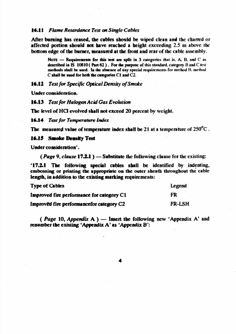
16.11 F lame Retadance Test on Single Cables
After burning has ceased, tbe cables sbould be wiped clean and the chanedor
affected portion should not have reached a beigbt exceeding 2.5 m above the
bottom edge of tbe bumer, measund at tbe frontand rear of tbe cable assembly.
NolE - Requinmnts for thii tn( an split in 3 categories Ihat is. A, 13, and C as
described ia IS loStO( Paa 62 ) . For thepwpose f this standard, category B and C icst
methods shall be used. in the absence of dny special requircmenls for method I% method
C shall be used for both the atepries Ct and C2.
16.12 Test for Specificptical Density of Smo& e
Under considention.
16.13 Test ir Halogen Acid Gas Evoluti on
Tbe level of HCl evolved shall not exceed 20 percent by weight.
16.14 Test or Temperatur e ndex
The measured value of temperature ndex &all be 21 at a temperatureof 250°C .
16.35 Smoke Dens&y Tast
Under corrPidention’.
(Page 9, c&use 17.2.1) -Substitute the foilowing clausefor the existing:
‘17.2.1 The following special cablea sball be identified by indenting,
embossing or printing tbe appropriateon tbe outer sbeatb throughout thecable
length, in iddition to tbe existing mirking requirements:
Type of CIbles Legend
Improved tin performance for category Cl FR
ImprovE?dirc performanceforcategory C2 FR-ISH
( Page 10,Appendix A ) - Insert tbe following new ‘Appendix A’ and
nnumbet the existing ‘Appendix A’ as ‘Appendix B’:
4

7/27/2019 IS-7098 Pt -1. (2)
http://slidepdf.com/reader/full/is-7098-pt-1-2 17/17
APPENDIX A( Cl aus es 0. 4 , . 5 , .5, 15.1.1 and 15.2.1 )
CLASSIFICATION OF CABLES FOR IMPROVED FIRE
PERFORMANCE
Category Environment
Description
01 Cables in open areas
Type
Cl Cables in constrained
areas
FR
c2 Cables in constrained FR-LSH
areas with limited human
activity and/or presence
of sophisticated systems
Cable Definition
Flame retardent. Single cable
self-extinguishing does not
propagate flame
Flame retardent. Does not propagate
fire even when installed in groups in
vertical ducts
Flame retardent cables with reduced
halogen evolution and smoke
(ETD09)Reprography Unit, BIS, New Delhi, India
5