is 15296 (2003): industrial automation systems - safety of ... · this indian standard which is...
TRANSCRIPT

Disclosure to Promote the Right To Information
Whereas the Parliament of India has set out to provide a practical regime of right to information for citizens to secure access to information under the control of public authorities, in order to promote transparency and accountability in the working of every public authority, and whereas the attached publication of the Bureau of Indian Standards is of particular interest to the public, particularly disadvantaged communities and those engaged in the pursuit of education and knowledge, the attached public safety standard is made available to promote the timely dissemination of this information in an accurate manner to the public.
इंटरनेट मानक
“!ान $ एक न' भारत का +नम-ण”Satyanarayan Gangaram Pitroda
“Invent a New India Using Knowledge”
“प0रा1 को छोड न' 5 तरफ”Jawaharlal Nehru
“Step Out From the Old to the New”
“जान1 का अ+धकार, जी1 का अ+धकार”Mazdoor Kisan Shakti Sangathan
“The Right to Information, The Right to Live”
“!ान एक ऐसा खजाना > जो कभी च0राया नहB जा सकता है”Bhartṛhari—Nītiśatakam
“Knowledge is such a treasure which cannot be stolen”
“Invent a New India Using Knowledge”
है”ह”ह
IS 15296 (2003): Industrial Automation Systems - Safety ofIntegrated Manufacturing Systems - Basic Requirements [PGD18: Industrial and Production Automation Systems andRobotics]


Wdk\\ \n @!m–l–mri3–
IS 15296:2003
1S011161 :1994
J-III*
qwd-T-a-TwR-qj3 W-bH-rq
Indian Standard
INDUSTRIAL AUTOMATION SYSTEMS—SAFETY OF INTEGRATED MANUFACTURING
SYSTEMS—BASIC REQUIREMENTS
ICS 25.040.30
Q BIS 2003
BUREAU OF INDIAN STANDARDSMANAK BHAVAN, 9 BAHADUR SHAH ZAFAR MARG
NEW DELHI 110002
February 2003 Price Group 10

Industrial and Production Automation Systems Sectional Committee, BP 18
NATIONAL FOREWORD
This Indian Standard which is identical with ISO 11161:1994 ‘Industrial automation systems—Safety ofintegrated manufacturing systems — Basic requirements’ issued by the International Organization forStandardization (ISO) was adopted by the Bureau of Indian Standards on the recommendation of theIndustrial and Production Automation Systems Sectional Committee and approval of the Basic andProduction Engineering Division Council.
The text of the international Standard has been approved as suitable for publication as Indian Standardwithout deviations. Certain conventions are, however, not identical to those used in Indian Standards.Attention is particularly drawn to the following:
a) Wherever the words ‘International Standard’ appear referring to this standard, they shouldbe read as ‘Indian Standard’.
b) Comma (,) has been used as a decimal marker in the International Standard while in IndianStandards, the current practice is to use a point (.) as the decimal marker.
In this adopted standard, reference appears to the following International Standard for which IndianStandard also exists. The corresponding Indian Standard which i? to be substituted in its place is listedbelow along with its degree of equivalence for the edition indicated:
Irrfernational Standard Corresponding Indian Standard Degree of
Equivalence
lS/TR 8373:1 9881) Manipulating IS 14662:1999 Industrial robots— Modifiedl)industrial robots—Vocabulary Vocabulary
Where there are no corresponding Indian Standards for the International Standards referred in this IndianStandard, reference to the relevant International Standard maybe made.
For the purpose of deciding whether a particular requirement of this standard is complied with, the-finalvalue, observed or calculated, expressing the result of a test oranalysis shall be rounded off in accordancewith IS 2:1960 ‘Rules for rounding off numerical values (revisec/)’. The number of significant places retainedin the rounded off value should be the same as that of the specified value in this standard.
‘I) lSO~R 8373 is revised as ISO 8373:1994 and IS 14662:1999 is identical to ISO 8373:1994.

IS 15296:2003
ISO 11161 :1994
Introduction
0.1 This International Standard is part of a series of standards dealingwith safety of industrial machines. It-has been harmonized with other rel-evant International Standards dealing with safety issues of industrialequipment.
The intent of this International Standard is to provide safety requirementsand guidelines for the design, construction, installation, programming,operation, use, and maintenance of integrated manufacturing systems. Itdescribes basic types of hazards associated with these systems and stepsto be taken to assess the risks associated with these hazards and toeliminate or reduce the hazards to an acceptable level.
Where specific points in this International Standard are considered to bein conflict with the requirements of other international standards (now orin the future), these requirements will be analysed to determine if they areto be included or deleted as system safety requirements.
0.2 This International Standard has been created in recognition of theparticular hazards which exist in integrated manufacturing systems incor-porating industrial machines and associated equipment.
The risks associated with these hazards vary with the types of inchstrialmachines incorporated in integrated manufacturing system and the appli-cation of such a system as to how it is installed, programmed, operated,maintained and repaired.
The requirements of this International Standard are aimed at minimizingthe possibilities of injuries to personnel while working on or adjacent toan integrated manufacturing system. This International Standard containsdefinitions, measures or procedures, and devices which are not specificto systems but can also apply to safety requirements for individual ma-chines and equipment. They are included in this International Standard tomake it more understandable or because no relevant international stan-dards exist.
Figure 0.1 shows a typical system with the assumption that all of thehazards presented by the system are contained within the work zone.These hazards are suitably protected by safeguarding means determinedby the risk assessment (see clause 4) and described in clauses 5 to 8 ofthis International Standard.
Where hazards are presented by equipment outside the work zone (e.g.electrical shock), it is intended that these hazards be suitably protectedby means described in relevant International Standards (e.g. iEC 204-1)

IS 15296:2003ISO 11161 :1994
which can be integrated by the procedures developed by the systemsupplier or user.
1.xi2-l. Localarea networkldata link
Safeguardsandinterlocks t
,::,:,,,:,,,:,,::,:::,,:,,,,:,,---.. .......... .... . . .... . ... ... . . . .... .. . .. . . . .... .. ....................................................-.,...........................................-..
*G+ZXE!3Figure 0.1 — Basic integrated manufacturing system
ii

IS 15296:2003
ISO 11161 :1994
Indian Standard
INDUSTRIAL AUTOMATION SYSTEMS—SAFETY OF INTEGRATED MANUFACTURING
SYSTEMS—BASIC REQUIREMENTS
1 Scope
This International Standard specifies the safety re-quirements for integrated manufacturing systems thatincorporate two or more industrial machines interc-onnected with and operated by a controller(s) ca-pable of being reprogrammed for the manufacturingof discrete parts or assemblies. It describes the re-quirements and recommendations for the safe instal-lation, programming, operation, maintenance, or repairof such systems (see figure 0.1 for the basic config-uration of an integrated manufacturing system).
This International Standard is not intended to coversafety aspects of individual machines and equipmentwhich may be covered by standards specific to thosemachines and equipment. Where machines andequipment of an integrated manufacturing system areoperated separately or individually and while the pro-tective effects of the safeguards provided for auto-matic mode are muted or suspended, the relevantsafety standards for these machines and equipmentshall apply,
2 Normative references
The following standards contain provisions which,through reference in this text, constitute provisionsof this International Standard. At the time of publi-cation, the editions indicated were valid. All standardsare subject to revision, and parties to agreementsbased on this International Standard are encouragedto investigate the possibility of applying the most re-cent editions of the standards indicated below.Members of IEC and ISO maintain registers of cur-rently valid International Standards.
ISO 3864:1984,
ISO 6385:1981,work systems,
Safety colours and safety signs.
Ergonomic principles in the design of
lSO~R 8373:1988, Manipulating industrial robots —Vocabulary.
ISO 10218:1992, Manipulating industrial robots —Safety.
CEI 204-1:1992, Electrical equipment of industrialmachines — Part 1: General requirements.
EN 418:1992, Safety of machinery — Emergencystop equipment, Functional aspects — Principles fordesign.
3 Definitions
For the purposes of this International Standard, thefollowing definitions apply.
3.1 awareness barrie~ Attachment or obstacle thatby physical contact warns of an approaching or pres-ent hazard.
3.2 barrier: Physical boundary to a hazard.
3.3 controlled stop: The stopping of machine mo-tion by reducing the command signal to O once thesignal has been recognized by the control but retain-ing power to the machine actuators during thestopping process. [IEC 204-1:1992, 3.12]
3.4 anabling davice: Manually-operated devicewhich, when continuously activated in one positiononly, allows hazardous functions but does not initiatethem. In any other position, hazardous functions arestopped safely.
3.5 guard: Machine element specifically used toprovide protection by means of a physical barrier.Depending on its construction, a guard may be calledcasing, cover, screen, door, enclosing guard, etc.
1
IS 15296:2003ISO 11161 :1994
3.6 hazard: Source of possible injury or damage tohealth.
3.7 hazard zone [area] [space]: Any zone withinand/or around machine~ in which a person is ex-posed to risk of injury or damage to health.
3.8 hazardous situation [condition] [motion]:Any situation in which a person is exposed to a hazardor hazards.
3.9 hold-to-run control device: Manually-actuatedstart and stop control device which initiates andmaintains operation of machine elements only as longas the control is actuated in a set position. The controlautomatically returns to the stop position when re-leased.
3.10 industrial machine; machine Individual com-ponent machine and associated equipment of an in-tegrated manufacturing system.
3.11 integrated manufacturing system; system:Group of two or more industrial machines workingtogether in a coordinated manner normally intercon-nected with and operated by a superviso~ controlleror controllers capable of being reprogrammed for themanufacturing of discrete parts or assemblies.
3.12 interlocking device (as used with a guard):Mechanical, electrical, or other type of device, thepurpose of which is to prevent the operation of sys-tem elements under specified conditions (generallyas long as the guard is not closed).
3.13 limiting device: Device which prevents a sys-tem or system elements from exceeding a designlimit.
3.14 iocal control: State of the system or portionsof the system in which the system is operated fromthe control pane! or pendant of the individual ma-chines only.
3.15 lockout: Placement of a lock on the energyisolating device (e.g. disconnecting means) in the“OFF” or “OPEN” position indicating that the energyisolating device or the equipment being controlledshall not be operated until the removal of the lock.
3.16 muting: Temporaty automatic suspension ofthe protective function of a safeguarding device dur-ing normal operation,
3.17 operational stop: Stop which stops the pro-duction process at a natural point in the workingprocess as soon as possible after its activation.
3.18 pendent Unit linked to the control system withwhich the system or portions of the system can beprogrammed (or moved).
3.19 person: Any individual.
3.20 peraonnei: Persons specifically employed andtrained in the use and care of a machine or manufac-turing system.
3.21 protective device Device (other than a guard)which reduces risk, alone or associated with a guard.
3.22 risk Combination of the probability of injuryoccurring and the degree of the injury or damage tohealth in a definite hazardous situation.
3.23 safeguard: Guard or protective device used ina safety function to protect persons from a presentor impending hazard.
3.24 safeguarded apace Space determined by thesafeguards.
3.25 eefeguerding: Those safety measures consist-ing of the use of safeguards to protect persons fromthe hazards which cannot reasonably be removed orsufficiently eliminated by design.
3.26 safe working procedure Specified procedureintended to reduce the possibility of injury while per-forming an assigned task.
3.27 suppiie~ Entity (e.g. designer, manufacturer,
contractor, installer, integrator) who provides equip-ment or services associated with the manufacturingsystem or portion of the system.
NOTE 1 The user may also act in the capacity of a suP-plier to himself.
3.28 task program: Set of motion and auxiliavfunctions instructions which define the specific in-tended task of the manufacturing system.
NOTE 2 This type of program is normally generated bythe user.
3.29 trip device Device which causes a system orsystem element to stop when a person or a part ofhis or her body goes beyond a safe limit.
3.30 troubleshooting; fauit finding: Act of meth-odically determining the reason that the system orportions of the system has failed to perform the taskor function as intended.
2

IS 15296:2003ISO 11161 :1994
3.31 uncontrolled stop: Stopping of machine mo-tion by removing power to the machine actuatorswhich cause hazardous conditions, all brakes or othermechanical stopping devices being activated (see IEC204-1).
3.32 user: Entity whomanufacturing system.
utilizes and maintains the
4 Safety strategy
4.1 General
This clause deals with the overall strategy of deter-mining the safety requirements for a system. Thisoverall strategy is a combination of the measures in-corporated at the design stage and those measuresrequired to be implemented by the user.
The design of the system shall be the first consider-ation while still maintaining an acceptable level ofperformance, This phase of the safety strategyshould:
— specify the limits or parameters of the system (see4.2);
— apply a safety strategy (4.3);
— identify the hazards (4 4);
— assess the associated risks (4.5);
— remove the hazards or limit the risks as much aspracticable.
Where it is not possible to reduce the risks to an ac-ceptable level by the above measures, provisions forsafeguarding in the design phase shall be consideredin such a manner that the flexibility of the system inits application is retained without impairing its safety.
In addition, information (e.g. written instructions,warning signs) concerning hazards -which are difficultto recognize shall be provided.
4.2 System specification
A system concept shall define the system specifi-cation. This includes or takes into account:
— description of functions;
—
—
—
—
—
—
—
—
—
—
layout and/or model;
survey about the interaction of different workingprocesses and manual activities;
analysis of process sequences including manualinteraction;
description of the interfaces with conveyer ortransport lines;
process flow charts;
foundation plans;
plans for supply and disposal devices;
determination of the space required for supply anddisposal of material;
available accident records;
study of similar system installations.
The designer shall have a specific and documentedidea of the probable human activities on the site, andin particular:
—
—
—
—
—
visits (presence of third parties not directly con-cerned by the operation);
process control and monitoring;
workpiece loading;
takeover of manual control by operator;
brief interventions not requiring disassembly;
— setting;
— troubleshooting;
— maintenance.
This information will enable the designer to work outa coherent, purposeful programme of action based onthe following elements:
— analysis of reference situations (old or more recenton other sites);
— allowance for effects of industrial variability
(equipment wear, dimensional variations of pro5-uct, etc.);
— participation of personnel having to work on thesystem in the future.
3

IS 15296:2003
ISO 11161 :1994
4.2.1 System design criteria
Besides the description of functions, all necessa~requirements to ensure safe operation should beconsidered in the design criteria list. This includes allprotective measures to effectively reduce the hazardslisted in 4.4 where they exist.
Such a design implies a coherent procedure whichminimizes the -effects of project fragmentation. Thisrequires:
—
—
—
—
integration of the man-machine interface;
early definition of the position of those working onthe system (in time and space);
early consideration of ways of cutting down onisolated work;
consideration of environmental aspects (e.g. qual-ity of air, lighting conditions, noise).
A system shall not be designed exclusively in termsof its working functions; it shall also be consideredfrom the viewpoints of its use and operation.
4.2.2 Project organization
During planning, design and construction of a manu-facturing system, safety measures especially thoserelated to the interactions between individual ma-chines shall be coordinated. This applies also wherea system consists of a combination of sectionsand/or single units from different suppliers.
The coordination of activities include, for example:
—
—
—
—
—
—
—
—
—
planning;
procurement;
delive~ and assembly;
installation procedure and stage of testing;
partial acceptance/acceptance;
delivery of the system in final working order;
system verification (runoff) including correction ofany faults or failures found;
maintainability;
ergonomic factors.
4.3 Application of a safety strategy
An integrated manufacturing system shall be de-signed and safeguarded to ensure orderly transportand installation as well as proper and safe use andmaintenance in accordance with the risk assessment
(see 4.5). To achieve these objectives the relationshipbetween human factors, the work being carried out,the hazards arising and the production process shouldbe taken into account.
The factors of noise, hazardous materials, heat, lowtemperature, radiation and similar influences of thephysical operating environment shall be consideredso as not to create health hazards.
The supplier(s) of the system (or parts of the system)shall state the expected conditions of the physicalenvironment and the requirements of the externalpowers sources and how they are to be connected toensure proper operation, The user shall ensure thateither these conditions are met or that alternativemeans are provided and that the system operatesunder these conditions according to the specification.
4.3.1 Design and development
All available knowledge concerning safety should’ beconsidered during the development of single units,sections of system and complete systems so that,through its application, accident and health hazardsshall be prevented or reduced to an acceptable level.This includes the clarity of the complete system, thesections of system and the single units. Particularly,the normal operating positions of personnel shallgrant sufficient vision of the flow of production andthe machining operations which may require addi-tional measures (e.g. video monitoring).
Normal positions for operating and maintenance per-sonnel shall be easily accessible and located outsidehazardous areas. Elements requiring routine mainte-nance (e.g. points of lubrication, setting mechanisms)
shall be arranged, where practicable, outside the haz-ardous areas. It is preferable to achieve the desiredlevels of safety by the use of nonhazardous elementsto remove or reduce hazards. Secondly, alternativeprocess sequences or working processes giving alower level of risk may be used.
Manually-operated start and stop controls shall be lo-cated in such a way that the hazard zone which isassociated with that control facility is clearly identified.
4

IS 15296:2003
ISO 11161 :1994
4.3.2 Safeguarding a) moving mechanical components in
Where the measures in accordance with 4.3.1 are notor only partially applicable in reducing risks to an ac-ceptable level, the safeguards given in clause 6 shallbe provided. These safeguards shall not complicateoperation and maintenance more than necessary. Thisincludes the clear arrangement in conjunction with thecomplete system, the sections of system and thesingle units.
Depending upon the design and application of thesystem, the use of a single safeguard or a combi-nation of several different safeguards may be neces-sary. The selection of the safeguards depends uponthe identified hazards.
Safeguarding means shall remain effective for all op-erating modes (see IEC 204-1:1992, subclause 9.2.4for suspension of safeguards under special condi-tions).
4.3.3 Warning signs and parsonal protectiveequipment
Where the measures given in 4,3.2 and 4.3.2 are notor only partially applicable, warning devices (see 6.6)and signs shall indicate the presence of the remaininghazards which are difficult to recognize.
The following hazards can be difficult to recognize:
— those due to unexpected movements;
— those due to unexpected effects of energy (e.g.by overpresswe, tension, rotation, gravity, noise,heat, low temperature, radiation); or
— those due to unexpected escape of hazardousmaterials.
Where necessary, the use of personal protectiveequipment shall be specified.
4.4 Hazard identification
Hazards can arise from
— the system itsetf;
— the interaction of the system with other machinewor equipment outside the system;
— the physical environment in which the system isused; or
— interactions between personne! and the system.
1) normal operation either individually or in con-junction with other elements of the systemor related equipment in the hazard zone,
2) unexpected operation (e.g. falling of mechan-ical components, tipping of the machinery);
b) power sources;
c) stored energy;
d) interferences
1) electrical [e.g. electromagnetic interference(EM I), electrostatic discharge (ESD), radio fre-quency interference (RFI)],
2) mechanical (e.g. vibration, shock);
e) hazardous atmospheres or materials
1) explosive or combustible,
2) corrosive,
3) radiation (e.g. ionization, thermal);
f) failure or fault of
1) protective means including removal, disas-sembly, or defeating,
2) components, devices, or circuits,
3) power sources or means of power distributionincluding fluctuations or disturbances,
4) information transmission;
g) human error
1) design, construction, or modification,
2) operating systems, application software, andprogramming,
.3) application and implementation,
4) setup including work handling/holding andtooling,
5) operation or use,
6) maintenance and repair,
7) documentation and training/instruction;Examples of sources of hazards are:
5
IS 15296:2003
ISO 11161:1994
h) ergonomic considerations
1)
2)
3)
4)
5)
lighting,
vibration,
noise,
climatic conditions,
operator control station design/layout.
4.5 Risk assessment
A risk assessment shall be performed which shallserve as a basis for determining safety objectives andmeasures.
Risks shall be reduced to an acceptable level. Toachieve this requirement, it is the intent of this sub-clause to provide guidance in the development ofprograms or plans to
.— create a safe working environment, and
— ensure safety and health of personnel.
Each identified hazard shall be assessed for its riskand appropriate safety measures shall be determinedand implemented to minimize that risk.
Hazards shall be ascetlained for the single units, theinteraction between single units, the operatingsections of the system, and operation of the completesystem for all intended operating modes/conditionsincluding conditions where normal safeguardingmeans are suspended for such operat”mns as pro-gramming, verification, troubleshooting, maintenance,or repair. This also applies where systems are modi-fied.
Risks shall be evaluated for normal operation whereconditions are clearly foreseeable including the inter-action of personnel as part of the production process.Where a hazard exists, normal production shouldavoid human irrtervention.
Risks shall also be considered for those parts of theprocess where it is foreseeable that there will be di-rect human intervention within the system (e.g.clearing blockages, setting, programming/teaching,troubleshooting, maintenance). It should be recog-nized that under these circumstances the normalcontrol sequences and some or all of the normalprocess safeguards may be suspended. Where this isthe case, special provisions should be made for localcontrol and safeguarding together with dedicated safesystems of work (e.g. lockout).
The hazardous situations which can occur in each areaof the system to which persons can have access,shall be identified.
4.6 Ergonomic considerations
4.6.1 Man-machhe interface
The following measures are designed to facilitate theactivities of automated system monitoring and dataprocessing. ‘
4.6.1.1 Direct view of operations
The site shall be designed to facilitate the acquisitionof information concerning sensitive points of the sys-tem; special atlention shall be paid to the layout ofobservation points or areas (it may be useful to pro-vide for viewing aids such as mirrors, video systems,etc.).
4.6.1.2 Information displayed
The user shall be able “to obtain all necessary infor-mation concerning the actual state of-the progress ofthe operating cycle. Comprehensive information con-cerning the state of the system should be availableon the man-machine interfaces. Special attention shallbe paid to the choice of information to be displayedon these interfaces and information which can be ac-cessed by the system operator on request.
This information shall be presented in a languagewhich takes into account the customary activity andtechnical culture of the system operators. For infor-mation display, the conditions listed below concerningits form and appearance shall be complied with
—
—
—
Lll= ~lly31Uil GlldldLLGl I>llb=’ UI SIyl Ial= 01 IU bul ILIUI=
shall be adapted to the viewing and manipulatingcapabilities of all operators;
the controls and information relating to a givenaction and monitoring of its result shall be locatedclose to one another;
the grouping of information shall promote diagno-sis (i.e. facilitate the identification of significantconfigurations of the technical system);
information allowing verification of the reliabilityof an indicator shall be located close to that indi-cator;
the conventions adopted shall be the same for alldevices (colours, abbreviations, direction of scroll-
6
IS 15296:2003
ISO 11161 :1994
—
—
—
At
*
ing, orientation of diagrams, etc.). Importance ofidentifying labels (see also iEC 204-l);
the design of display systems shall be such as toallow detection of display-system malfunctionsand repair of the system;
allowance shall be made for the capability of thedevice to evolve with evolutions in production,user population, etc.;
duplication: it is often necessa~ for the same in-formation to be displayed at several locations onthe site.
the site design stage, consideration shall be givento the possibility of the users storing in memory sig-nificant events (settings, oil changes, drifts, contin-gencies, incidents). Storage in memory should makeit possible for the user to trace the history of thesystem.
In addition, the information conveyed via severalinterfaces shall be interconnected to ensure the co-herence of such information, especially when theprinciple of redundancy is employed.
4.6.1.3 Manually-operated control devices
The design and location of manually-operated controldevices should:
— ensure that the state of each power actuated de-vice is visible from the position of the manually-operated control device;
— ensure that functions and statuses are defined anddisplayed explicitly for the operator;
— harmonize the manually-operated control devices
(e.g. designation, positions) by enswing consist-ency between the various control parts of a givensystem;
— adapt the shapes and sizes of the actuators of thecontrol devices to ensure that they can be actu-ated without error by workshop operators.
The effects of the actuation of any manually-operatedcontrol device shall be clearly defined. The state ofthe actuated control device shall be made clearly ap-parent.
4.6.-2 Human interventions
4.6.2.1 Control and maintenance activities
Interventions areas shall be sized and arranged so asto provide sufficient space for movement and forperforming the necessary tasks with minimum risk.
Provisions should be made, in particular, for
— areas for movement by those working on the sys-tem, avoiding, insofar as practicable, changes oflevels and lengthy movements, and with provisionfor crossover points;
— a working space or platform for all long, frequent,or high-elevation interventions which takes intoaccount the aspects of posture, body dimensions,
—
—
.
the environment, and task;
layout of interfaces, central and decentralizedconsoles (stationary or mobile) in such a way as toallow viewing of the part actuated, to limit timeconstraints and minimize risks related to faults incommunication between operators;
a lighting level in work areas and for parts of thesite requiring special monitoring which is appro-priate for the operations to be performed. Careshould also be taken that visibility is not disturbedby phenomena such as glare or reflections. Incertain cases, provisions should be made for thepossibility of lighting adjustment (intensity, orien-tation);
lifting bolts or other devices built into the equip-ment and/or forming part of the site and the useof s~ecial handling facilities to facilitate theassernbly/disassem61y of the system.
4.6.2.2 Predominantly manual activities
Application of ergonomic measures ana datautes to improvement of the safety level bytask completion easier and by decreasing the
contrib-makingnumber
of human errors during interventions (e.g. repairing,maintenance, checking, programming, operating). Thedesign of system elements on which human inter-vention is intended shall take into account humancharacteristics such as size, posture, strength, move-ments, and physical ability (ISO 6385).
Care should be taken to ensure the operators
— maintain normal body position;
— can communicate (visually and orally).
7
IS 15296:2003
ISO 11161 :1994
4.7 Marking
The system shall be provided with a specific identifi-cation with the following information (as a minimum):
— name and location of manufacturer/supplier;
— system identifier;
— appropriate certification (where required).
4.8 Requirements for documentation
The system documentation shall be written in thelanguage(s) agreed between the user and the supplierprior to the acceptance of the order and contain (as aminimum) the following:
a)
b)
c)
d)
e)
f)
9)
h)
i)
a clear, comprehensive description of the systemand its installation including mounting and con-nection to external energy sources;
a repetition of the markings found on the system
(see 4.7);
the system performance specifications;
external power source(s) specifications;
physical environment specifications (e.g. lighting,vibration, and noise levels, atmospheric con-taminants);
a description of potentially hazardous conditionsand how to avoid them (e.g. lockout, blocking,pinning);
how to recognize abnormal performance and howto correct it;
information on the
1) programming,
2) operation,
3) frequency of inspection,
4) frequency and method of functional testing,
and
5) guidance on the repair and maintenance ofthe system and its safeguards;
a recommended procedure for maintaining a re~cord of the task program to assist personnel inoperating or troubleshooting;
j) a description (including interconnecting diagrams)
k)
1)
m)
of the safeguards, interacting functions, andinterlocking of guards with hazardous movementsparticularly with interacting installations;
a description of the safeguarding means andmethods when the primary safeguards are sus-pended;
a description (including diagrams) for the inter-faces for the connection of control and power cir-cuits;
procedures for adjustment of the limiting devices.
The instruction manual for a system shall include thevarious specific manuals for its component parts.
5 Design requirements for safetyfunctions of the control system
5.1 General
The following requirements apply to the control as-pects (e.g. electrical, hydraulic, pneumatic, mechan-ical) of integrated manufacturing systems.
Control systems shall be designed and constructed ina manner that they cause no hazards to persons whenthey are used according to their specification duringnormal operation (see 8.3) or manual operation (see8.4). This applies also to the interaction between acomplete control system with separate unit controlsystems in addition to unit control systems in relationto each other.
The electrical equipment of a system shall be in ac-cordance with IEC 20z1-1:1992 and in particularclause 9.
The electrical power supply and the connection of theearthing (grounding) conductor shall be in accordancewith the supplier’s recommendations.
5.2 Interferences
The design and installation of the system shall incor-porate good engineering practices which protect con-trols and control systems from sources ofinterference. If risks may be foreseen as a result ofinterfererwe, then separate safeguards are required toensure that interference with control functions doesnot present risks whenever the machines are put totheir intended tasks.
Examples of sources of interferences include:
— electromagnetic interference (EM I);
8

IS 15296:2003
ISO 11161 :1994
— electr.ostatic discharge (ESD);
— radio frequency interference (RFI);
— vibration/shock;
— airborne noise;
— light;
— radiation.
5.3 Limitation of fault effects for safety
functions
The control system shall be designed, constructed,and installed or applied to ensure that a single controlcomponent failure within the system does not pre-vent stopping action from taking place but will prevent
F
Start
I Ist Fault I
initiation or successive system cycles from occurringuntil the failure has been corrected.
This requirement does not apply to those componentswhose failure cannot cause hazardous conditions.
When analysing faults, the following shall be consid-ered (see figure 1):
— a single fault shall not give rise to any situationhazardous to persons;
— a first fault which has not been recognized in con-junction with a further fault (second fault) shall notgive rise to any situation hazardous to persons.
It is assumed that two independent faults do not ap-pear at the same time, but the designer shall take intoaccount common mode failures.
Yes
Na
tUndue,provide [essatlon ofother measures fault assessment
Figure 1 — Fault assessment

IS 15296:2003
ISO 11161 :1994
Failure consideration shall be made to maintain thesafety-technical requirements in the case of failureand/or to ensure a detection of certain types of fail-ures. Consequently, the development and assess-ment (fault analysis) shall be based upon assumptionof the failure modes of the different components.
5.4 Safety measures
5.4.1 Safety meesures by the control
In addition to the requirements of 5.3, proven circuittechniques and components (see IEC 204-1:1992,subclause 9.4.2.1 ) shall be used together with one ormore of the following examples of safety measures:
a)
b)
c)
d)
Partial or complete redundancy (seeIEC 204-1:1992, subclause 9.4.2.2).
Control component failure protection of electrical,electronic or fluidic systems frequently consistsof multiple, independent parallel or series circuit~or components arranged to meet the require-ments of this subclause. Protection against theconsequences of failure of control componentsshould not depend solely upon simple redun-dancy,
Component redundancy is the use of two or morecontrol components in parallel or series circuitsand is used to ensure reliable operation. However,
failure of one of the redundant components cango undetected, allowing the appearance of safeoperation. When the additional element(s) of theredundant circuit subsequently fails, an unsafecondition can occur. Monitoring and response tosuch single failures is essential:
Use of diversity (see IEC 204-1:1992, subclause9.4.2.3),
Reduced speed (or power) of hazardous move-ments.
The application of this measure assumes that a
person can withdraw in time from a hazard com-ing from hazardous movements. This can be as-sumed if the reduced speed does not exceed15 m/min in case of hazardous movements with-out a crushing or shear hazard (due to pushing)and it does not exceed 2 m/min in case of haz-ardous movements with a crushing or shear haz-ard. These values also apply if an enabling deviceis used at reduced speed;
Monitoring of control functions providing safetymeasures.
10
e)
f)
The application of this measure (can also be car-ried out by simulation) assumes that monitoringcarried out in a positive mode at fixed intervalsdetermines how a consideration of the risk as-sessment will recognize an occurred fault and, incase of a recognized fault, will induce a safetysignal (most of the time a shut-off signal);
Enabling device (see 6.5).
The application of this measure assumes that theperson who uses the enabling device will recog-nize hazards in time to take immediate steps toavoid them;
Delockable non-return valves, cyclic switching ofslide valves which are infrequently actuated, forceactuated valves, impulse valves without springactuation.
Considerable energies can be stored in hydraulicor pneumatic systems. It shall, be assured thatthese do not lead to hazardous movements.Stored energies may be suited to induce safetyfunctions (e.g. through restoring movements). Ifnecessary additional measures shall be providedagainst later hazardous movements (e.g. due todrop in pressure, mains isolation, Ieaka.ges, linebreaks) such as, for example, mechanical forcelocked or positively located supporting facilities ordelockable non-return valves.
5.4.2 Additional safety measures
Where safety measures by the control alone are notsufficient to protect against hazardous fault effects,complementary measures such as mechanical safetyprecautions shall be taken.
5.4.3 Combination of safety measures
Usually, a combination of safety measures are re-quired. The safety measures to be .taken shall be de-termined during the design of the control system foreach component of the integrated manufacturingsystem which has to fulfil safety functions and bymeans of risk assessment (see 4:5). Where a combi-nation of system components causes new safety re-quirements, these shall be solved at the system level.
5.5 Manually-operated control devices
Manually-operated control devices shall be readilyvisible, identifiable and appropriately marked orIabelled. Those related to safety measures shall bepositioned for safe operation without hesitation, lossof time, or ambiguity. These shall be located outside

IS 15296:2003
ISO 11161 :1994
the hazard zone except for certain devices (e.g.emergency stop device, enabling device) when re-quired as part of the safety measures.
5.6 Status indicators
Status indicators, where provided, shall indicate theoperating condition of the system or a particular zonewithin the system.
5.7 Selection -of the operating modes of thesystem
The control equipment shall have provisions for atleast the following operating modes:
—
—
—
,normal (production) mode: all normal safeguardsconnected and operating;
operation with some of the normal safeguardssuspended;
operation in which system or remote manual in-itiation of hazardous situations is prevented (e.g.local operation, isolation of power to or mechanicalblockage of hazardous conditions).
The means for selection of operating modes shall becapable of being supervised for certain operations
(e.g. programming, verification, maintenance). Wherethese operating conditions can present hazardous sit-uations, interlocked access’ to the hazard zone(s) shallbe required.
5.8 Control measures for the Suspension ofsafeguards
Controls shall be designed in such a way that where
—
—
—
—
—
setup [see 8.4.2 a)];
programming [see 8.4.2 a) and 8.5];
program verification [see 8.4.2 b) and 8.6];
troubleshooting (fault finding, observation of pro-duction cycles) [see 8.4.2 b) and 8.7];
maintenance [see 8.8]
cannot be performed from outside the safeguardedspace, the relevant safeguards may be suspended toallow personnel to enter the hazard zone. The sus-pension of those safeguards should preferably betime limited (e.g. 10 s). The suspension may be by alockable selection device or by other devices with anequivalent level of safety.
A sufficient level of safety can be achieved by othermeasures than lockable selection device only.
When personnel are required to be in the hazard zone,the following safety measures shall be provided in thecontrol system in accordance with the requirementsof clause 8:
— hold-to-run;
— enabling device;
— reduced speed;
— reduced power;
— portable emergency stop.
When safeguards are suspended as above, it shall notbe possible for a hazardous situation to be initiatedfrom outside the hazard zone.
Normal production shall only be possible when theprotective effects of safeguards are reestablished.
To assist operating personnel during the suspensionof safeguards, consideration shall be given to provid-ing aids. The aids may include
— indication of the status of safety relatedfunctions/circuits and actuators which can causehazardous conditions;
— indication of conditions of essential elements (e.g.status of work in progress, parameters such asposition of elements of the equipment, temper-
ature).
5.9 Local operation
Where local operation of the equipment in a hazardzone is provided, the remaining portion of the systemshall be notified of this condition. Means for the se-lection of local operation shall be designed and con-structed to allow the system operator or others in aparticular zone to locally operate equipment withinthat zone but prevent any external means from actu-ating any equipment within the zone while the zoneis under local operation.
Where a system or zone is provided with local oper-ation, the means for selection shall be:
— located outside Ihe hazard zone; and
— capable of being controlled by the operator orother designated personnel (e.g. key lock switchor access code).
11
IS 15296:2003
ISO 11161 :1994
Machines and related equipment in local operation available to achieve the stop and then removal ofshall be under the direct control of the system oper- power when the stop is achieved;ator. No hazardous conditions may be actuated froma remote or external location when under local con- — Catego~ 2: a controlled stop with power lefttrol. available to the actuators which cause hazardous
conditions.Switching between local and remote or externaloperation shall not by itself create any hazardous sit- Categories O and 1 shall be designed in accordanceuations. with 5.3.
5.10 Stafiing
}t shall be possible to start the system, or machinesand related equipment within operating zones, of thesystem, from a control station located outside theassociated protected zone provided that all safe-guards associated with that zone are in place andfunctional, and all normal operating conditions havebeen met.
When it is required that the system (or a particularzone) be started concurrently from several controlstations, these starting means shall be interlocked toprevent starting from less than the required numberof stations.
Conversely, when for reasons of safety, a particularzone of the system is to be started from a single pointof control, the other start controls shall be so de-signed and implemented to prevent starting of otherzones of the system or that zone of the system fromother locations.
5.11 Stopping
Each system or zone within the system shall have, asa minimum requirement, provisions for two levels ofstopping; one related to safety measures and theother related to normal operating conditions. Normaloperating conditions includes safety measures. Theimplementation of the stopping functions shall bebased on the risk assessment.
5.11.1 Stop functions
Stop functions shall override related start functions.Stop functions should be selected according to therisk assessment based on the categories listed below.
There are three categories of stops as follows:
Each zone shall be equipped with a category “O or 1stop (or both) depending upon the risk assessment,Restoration of normal power after a catego~ O or 1stop shall not by itself cause hazardous conditions.
5.11.2 Emergency stop
The system shall be provided with one or moreemergency stop functions which can be applied to theentire system or to clearly distinguishable zoneswithin the system.
In the case of clearly distinguishable zones within asystem, those zones should have their own emer-gency stop function which applies to that zone only.Where one or more zones are in an emergency stopcondition, the system (or remaining portions of thesystem) shall be notified of the condition. After theactuation of an emergency stop device for a clearlydistinguishable zone, no hazards shall exist at theinterface between this zone and other areas of thesystem.
Where the emergency stop function is implementedby an electrical circuit, it shall be in accordance withIEC 204-1 and in accordance with EN 418 in the caseof using hydraulic power for drive power.
Human intervention by designated personnel shall berequired to reset the emergency stop circuit. Reset-ting of the emergency stop shall not initiate or restartany hazardous motions or create any hazardous con-ditions,
Each control station shall be provided with a manuallyoperated emergency stop device which shall be as-sociated with the clearly distinguishable -zone. Theactuators of manually-operated emergency stop de-vices shall be in accordance with IEC 204-1.
5.11.3 Interruption by safeguards
— Category O: stopping by immediate removal of The safeguard (e.g. a trip device or interlocked guard)power to the actuators which cause hazardous shall be connected to a stop function of category Oconditions (i.e. an uncontrolled stop, see 3.31). or 1. The activation of these safeguards is in many
cases a patl of the working procedures for the sys-— Category 1: a controlled stop (see 3.3) with power tern. It is therefore essential that this stop function
to the actuators which cause hazardous conditions allows an easy restart of the system or portion
12

IS 15296:2003
ISO 11161 :1994
thereof. When this is not practicable because of theproduction process, thenan operational stop functionshall be provided which can be activated before thesafeguards are activated. This operational stop func-tion shall redesigned to stop the production processat a natural point in the production process to avoiddamage to the machine, product and process.
When an operational stop is provided, and where it isnot possible for safety reasons to stop a processduring any production cycle or part thereof, the elec-trically interlocked guards with guard locki~ shall beused for safeguarding to prevent personnel enteringthe hazard zone until the production cycle has endedand all hazards have been eliminated.
5.11.4 Operational stop
Operational stop functions which are category 2 stopsshall be in compliance with IEC 204-1, This level ofstopping is intended as a functional or operationalstop and not as a safety measure.
5.12 Emergency movement
Means shall be provided to provided movement ofsystem elements under emergency conditions. Thesemeans are for example:
a) with power off:
— venting of relief valves to repressurize sys-tems under pressure;
— manual release of mechanically-actuatedbrakes provided that additional hazards are notcreated;
b) with power on:
— manual control facilities of power-pilotedvalves/drives;
— control facilities to start counter motions.
5.13 Power interruption or fluctuation
Interruption or fluctuation in any of the power sourcesshall not cause any hazardous situations or it shall in-itiate an immediate stopping action. Restoration ofpower by itself shall not cause any hazardous situ-ations or restart the system.
5.14 Power disconnection
Disconnecting means for all externally supplied powersources shall be provided and marked or Iabelled to
identify the power source. Externally supplied powersources shall have a disconnecting means with lock-out capabilities.
The entire system or clearly distinguishable zoneswithin the system shall have means to disconnecteach of its power sources. These means shall be lo-cated in such a way that not person will be exposedto hazards and shall have a lockout capability.
NOTE 3 For requirements of electrical supply discon-necting devices, see IEC 240-1.
5.15 Stored energy
Means shall be provided for the isolation, contain-ment, or controlled release of stored energy that cancreate a hazardous situation.
5.16 Safety related parameters
If preset limits for safety related parameters are ex-ceeded, the control system shall initiate appropriatemeasures to eliminate or reduce the hazard. Examplesof safety related parameters are displacement, speed,temperature, and pFessure.
6 Design and safeguarding of thesystem
6.f General
The following safeguards may be used for the pro-tection of persons from hazardous situations providedthey meet the requirements of 5.3:
—
—
—
In
fixed or movable guards;
trip devices used with interlocking (e.g. lightbeams/curtains, pressure-sensitive plates/press-ure-sensitive mats, tactile sensors);
person location dependent safety measures (e.g.two-hand controls, enabling devices).
addition, means such as awareness barriers,awareness devices and signals, warning signs andsymbols, safety markings, and safe working practicesmay be used but not ● as a substitute unless deter-mined by the risk assessment.
6.2 Safeguarding requirements
This subclause specifies the requirements for thesafeguarding of the system.
13

IS 15296:2003
ISO 11161 : 1994
6.2.1 Identification of the perimeter
The perimeter of the system or zones within the sys-tem should be de~ined or marked. Where hazardzones occur at the perimeter, safeguarding -shall beprovided to prevent or detect personnel inadvertentlyreaching into or entering the hazard zone. Detectionof entry shall prevent initiation of hazardous motionswithin the hazard zone or shall cause cessation ofhazardous motions before personnel are exposed tothe hazard.
Means provided to access the system from the per-imeter shall prevent personnel from inadvertentlyreaching into a hazard zone.
6.2.2 Safeguarding within the system
Where a hazard, either immediate or impending, ex-ists between individual machines or other compo-nents of the system
— guards shall be provided to prevent personnelfrom entering or reaching into a hazard zone, or
— trip devices shall be provided to detect personnelreaching into or entering a hazard zone.
Detection shall prevent initiation of hazardous situ-ations, cause immediate stopping action (see 5.1 1.3)of hazardous situations within the hazard zone orprevent hazardous situations from. entering the hazardzone.
6.2.3 Safeguarding at the individual componentmachines
Where personnel are exposed to hazards associatedwith an industrial machine or other equipment withinthe system, safeguarding shall be provided in accord-ance with the appropriate International Standard.Where such a standard does not exist, the require-ments of this International Standard shall apply or ad-ditional safeguarding shall be provided.
6.2.4 Safeguarding during manual operation
Proper safeguarding shall be provided for use duringsetup, programming, program verification, trouble-shooting, maintenance and repair operations.
During setup, maintenance, and repair operations,hazardous situations within the hazard zone(s), shallbe under local control.
6.3 Guards
The following types of guards shall be consideredwhen specifying the safeguarding of the system:
—
—
—
fixed which can only .be detached by the use oftools;
movable (e.g. adjustable, insertable, reversible);
perimeter with or without gates or points of ac-cess (e.g. material load/unlo~d).
NOTES
4 A guard may act alone; it is then only effective when itis closed in conjunction with an interlocking device, or withan interlocking device with guard locking; in this case pro-tection is ensured whatever the position of the guard.
5 Closed means kept in place for a fixed guard.
Fixed guards shall be kept in place
— either permanently (e.g. welding);
— or by means of fasteners (e.g. screws, nuts) mak-ing removal/opening impossible without the useof tools.
Movable guards are those connected by a mechanicalmeans to the machine frame or adjacent fixed ele-ment, generally via hinges or slides, and which canbe opened without the use of tools. They shall beinterlocked to initiate stopping of hazardous condi-tions and prevent initiation of hazardous conditions ifthe guard is open.
Movable guards shall
— be located such that entry is into a nonhazardouszone;
— prevent entry into a hazard zone until hazardous
conditions ceae;
— when opened, prevent hazardous conditions frombeing initiated or cause the initiation of immediatestopping action of hazardous conditions within ahazard zone or prevent hazardous conditions fromentering a hazard zone;
— not inhibit egress of personnel from the system.
Guards used to safeguard personnel from hazardsassociated with the system shall be designed, con-structed and applied to
14
IS 15296:2003ISO 11161 : 1994
.—
—
—
—
—
—
prevent personnel from inadvertently reaching intoor entering a hazard zone over, under, around orthrough the guard;
not in or of themselves create a hazard to person-nel or with other elements of the system;
have a clearly defined protective position (e.g. byuse of hinges, stops, rails);
provide visibility into the work zone appropriate forthe particular operation;
be installed in such a manner that they are notreadily removable and shall be attached to a fixedsurface;
use materials of such design and strength to pro-tect personnel from hazar& associated with “theintended use of the system and withstand normaloperational and environment forces.
6.4 Interlocks and protective trip devices
6.4.1 Interlocks
The interlock shall be designed and constructed inaccordance with 5.1. Together with the guard withwhich it -operates, it shall be installed and adjusted sothat when in use:
— the control system through the interlock preventsthe system or that portion of the system controlledby the interlock from normal operation until theguard is closed and reset where necessary (see6.4.3);
— closing shall not initiate normal operation. Initiationshall be a deliberate action by the operator (see5.10);
— either the guard remains locked closed until thehazard has passed (interlocking guard with guardlocking) or opening the guard while the system isworking gives a category O or category 1 stopfunction (interlocking guard);
— when an interlock has been reestablished, it shallbe possible to restart the system or part of thesystem from the stopped position provided thatthis does not create other hazards;
— interruption of the power sources may be suffi-cient to eliminate the hazard before access ispossible. Where the hazard cannot be eliminatedimmediately by power interruption, the interlock-ing system shall need to include a guard lockingor a braking system;
—
—
where whole body access to the safeguard spaceis possible and the reset device cannot be placedso that there is a good visibility for checking thatno person is present within the safeguarded spaceadditional means, which prevent restart when aperson is in a safeguarded space, shall be taken;
actuation of an interlock installed to protect againstone hazard (e.g. stopping hazardous situa~ons)does not create a different hazard, e.g. the releaseof hazardous substances into the work zone.
Selection of the preferred system of interlocking fora particular application shall take account of the riskassessment (see 4.5) and the frequency of opening amovable guard for access (i.e. human intervention) tothe hazard zone:
— movable guards for frequent access (e.g. on oper-ation areas for loading and unloading of products)with interlocking devices based on componentduplication and/or monitoring;
— movable guards for infrequent access (e.g. to car~out adjustment or maintenance) with interlockingdevices based on inherently safe design.
A guard associated with an interlocking device (inter-locking guard) shall be such that
— the hazardous functions covered by the guardcannot operate until the guard is closed;
— where the guard is opened while the hazardousfunctions covered by the guard are operating, astop instruction is given;
— when the guard is closed, the hazardous functionscovered by the guard can operate but the closureof the guard by itself does not initiate their oper-ation.
A guard associated with an interlocking device and aguard locking device (interlocking guard with guardlocking) shall be such that
—
—
—
the hazardous functions covered by the guardcannot operate until the guard is closed andlocked;
the guard remains locked closed until the risk ofinjury from the hazardous functions covered by the
guard has passed;
when the guard is closed and locked, the hazard-ous functions covered by the guard can operate
15

IS 15296:2003
ISO 11161 : 1994
but the closure of the guard does not by itself in-itiate their operation.
6.4.2 Protective trip devices
The following types of protective trip devices shall be
considered when designing the safeguarding of thesystem:
— pressure sensitive mats and
— electrosensitive protectivebeams and curtains);
— tactile sensors.
The consideration of the designthe above.
pads;
devices (e.g. light
shall not be limited to
Protective trip devices used to protect personnel fromhazards associated with the system shall
— detect personnel reaching into or entering thehazard zone through the plane or area protectedby the device;
— have an identifiable minimum object sensitivitysuch that an object of equal or greater size ormass will be detected anywhere within the sens-ing field regardless of the plane of intrusion;
— be located at a distance from the hazardous con-dition such that the condition ceases prior to per-sonnel reaching the hazard;
— prevent a hazardous condition from being initiatedor initiate an immediate stopping action of thehazardous condition within the hazard zone or in-itiate stopping action of hazardous conditions be-fore they can reach personnel;
— not in or of itself create a hazard.
Restarting of normal operation shall require that theinterruption of the device shall be cleared and resetwhere required (see 6.4.3), and that the system isreinitiated by normal means (see 5.1 O).
All areas of entry into the hazard zone not protectedby the device shall be protected by other safeguard-ing.
Muting of the device shall be permitted when it isnecessary for workpieces, material or components toenter or exit a hazard zone of the system.
The device or its interface shall incorporate a meansto visually indicate when it is in use, when it is func-
tioning properly, whendetected an intrusion.
it is muted and when it has
The ability to detect an intrusion shall not be adverselyaffected by changes in the intended physical environ-ment or normal operating conditions of the system.
Devices that require adjustments or that incorporateoptional features or functions shall be designed orconstructed such that these adjustments or featuresare capable of being supervised and/or locked.
The device shall have a maximum response time thatis not adversely affected by adjustments or changesin the conditions of the intended physical environ-ment.
Protective trip devices shall be positioned so as toprevent access to the hazard(s) until it has beeneliminated or reduced to an acceptable level.
Where whole body access to the safeguarded spaceis possible and the reset device cannot be placed sothat there is good visibility for checking that no personis present within the safeguarded space additionalmeans, which prevent restart when a person is in asafeguarded space, shall be provided.
6.4.3 Resetting
Resetting of the interlocks and other protective de-vices is required where whole body access is poss-ible. Reset shall ensure given conditions beforeinitiating operation.
Reset shall
— ensure that all safety functions and protective de-vices are active;
— not initiate motion or a hazardous situation;
— be by deliberate manual action;
— prepare the machine system for all starts;
— be inoperative during the operating mode of themachine.
The manually-operated resetting device shall be lo-cated outside the hazard zone from which there isgood visibility for checking that no person is presentwithin the hazard zone.
Resetting in the safeguarded space may be allowedas an exception for the emergency stop device andthe enabling device.
16

IS 15296:2003ISO 11161 : 1994
6.5 Enabling devices
Where an enabling device is provided as part of thesystem, it shall be designed to allow motion or otherhazardous situation when actuated in one positiononly. In any other position, hazardous situations shallbe stopped safely. Operation of the device by itselfshall not initiate hazardous situations.
When an enabling device is required, it shall be con-nected to a category O or categoty 1 stop (see5,11.1).
Enabling devices shall be designed in compliance withthe ergonomic principles. A simple defeat shall beprevented.
There are two types of enabling devices as follows:
a) two-~ osition:
1) position 1: off-function of the switch (actuatoris not pushed),
2) position 2:pushed);
b) three-Dosition:
1)
2)
3)
\Nhen
position 1:pushed),
position 2:
enabling function (actuator is
off-function (actuator is not
enabling function (actuator ispushed to its mid-position),
position 3: off-function (actuator is pushedpast its mid-position).
returning from position 3 to position 2 the en-abling function-shall not become active.
Other solutions may be used where they provide anequivalent level of safety. A hold-to-run control devicewhich meets the requirements of 5.3 may be used
as an alternative to the enabling device and used forthe same purposes.
6.6 Warning devices
Warning devices may be used in addition to, but notas a substitute for, safeguarding except where deter-mined by the risk assessment.
Warning devices shall indicate or announce an im-pending or present hazard within the system by tac-tile, visual or audible means. Examples of warningdevices can include but are not limited to
a) tactile
1) curtains,
2) chains or ropes,
3) railings;
b) visual
1) signs,
2) floor markings,
3) lights (steady, flashing, rotating);
c) audible
1) bells,
2) horns,
3) whistles,
4) sirens.
Warning devices shall be designed, constructed andinstalled such that they shall provide a distinguishableindication (e.g. flashing light) of an impending orpresent hazard.
NOTE 6 For the use and frequency of flashing lights, seeIEC 73.
6.7 Safety markings
Safety markings (e.g. signs, symbols, labels, warningpaint) shall be of a durable material, easy to under-stand, represent a contrast to the surrounding back-ground and applied in a durable manner. See alsoIS0,3864.
Safety signs should be applied where additional indi-cation of a potential hazard (e.g. existing remainingenergies, and to mark protected areas) is required.
6.8 Safe working procedures
Itis recognized that for certain phases of the systemlife (e.g. commissioning, process changeover, clean-ing and maintenance) it may not be practicable to de-sign completely adequate safeguards to protectagainst every hazard especially where certain safe-guards may be suspended. For such conditions, ap-propriate safe working procedures shall, as far aspossible, be addressed in the manual.
17
IS 15296:2003
ISO 11161 :1994
6.9 Openings for loading and unloading of
material
6.9.1 General
This subclause applies to openings provided for thepassing of material into or out of the system whichare small enough to prevent entrance of persons.Where these openings are large enough to allow theentrance of persons, the requirements of 6.2 shallapply,
6.9.2 Manual loading and unloading
Personnel shall not be exposed to hazardous situ-ations during manual loading and unloading ofworkplaces of parts.
6.9.3 Automatic loading and unloading
Personnel shall not reach hazardcus points or areaswhen automatic loading and unloading takes placeand they shall not be exposed to hazardous condi-tions.
6.10 Stopping time/distance
When relevant, the supplier shall state the stoppingtime or distance (or both).
7 Training, installation,and functional testing
7.1 General
commissioning
This clause contains provisions and requirements fortraining of personnel and installing and functionaltesting the system prior to its use in normal operation.
7.2 Training
Instructions as necessary for the safe use of the in-tegrated manufacturing system shall be established.
The user shall ensure that personnel who program,operate, maintain or repair the systems are ade-quately trained and demonstrate competence to per-form their tasks safely. Training shall include, but notbe limited to
a) a review of applicable standard safety proceduresand the safety recommendations of the suppliersof the system and its component elements;
b) a clear definition of assigned tasks;
c)
d)
e)
f)
g)
h)
identification and explanation of all control devicesand their functions used in performing the as-signed tasks;
identification and clarification of lockout proce-dures;
identification of the hazards associated with theassigned tasks;
the method(s) of safeguarding (including the safeworking procedures) from the identified hazards;
the method for functional testing or otherwiseensuring the proper functioning of the safeguards;
the method for testing or otherwise ensuring theproper functioning of the safeguards and inter-locks.
7.3 Installation
The system shall not be installed in accordance withthe manufacturer’s requirements with the safeguard-ing methods identified by the hazard analysis and thetisk assessment. The user shall review the safety re-quirements to ensure that the appropriate safeguardsare applied prior to commissioning.
When the safeguarding methods are not in place priorto commissioning and functional testing, interimmeans of designating (e.g. markings, awareness bar-riers, warning signs) the hazard zones shall be in placebefore proceeding.
7.4 Commissioning and functional testing
7.4.1 Commissioning
The safety requirements shall be reviewed to ensurethat appropriate safeguards are in place prior to com-missioning.
Where integrated manufacturing systems, sectionsof systems or single units are installed and tested andthe required safety measures for the particular modesof operation according to this International Standardare not practicable, the following requirements (as aminimum) shall apply:
— the necessav safety measures shall be deter-mined and implemented;
— only authorized personnel are allowed in hazardzones;
— emergency stop function shall be active;
18

IS 15296:2003
ISO 11161 :1994
— designate (e.g. mark, awareness barriers, warningsigns) the hazard zones;
— the locking devices to prevent unintended oper-ation (e.g. keys, padlocks);
— provide personal protective equipment and ensuretheir use;
-- provide means for rescue (see 5.1 2).
7.4.2 .Functional testing
The manufacturer’s instructions for functional testingof the system shall be followed. An initial start-upprocedure shall include, but not necessarily limited to,the following:
a) before applying power, verify that
1)
2)
3)
4)
5)
6)
7)
the system including its individual machinesand associated equipment has been properlymounted and is stable,
the electrical connections are correct and thatthe power (i.e. voltage, frequency, interfer-ence levels) is within specified limits,
the other utilities (e.g. water, air, gas) areproperly connected, identified and withinspecified limits,
the peripheral equipment is properly con-nected,
the limiting devices that establish the re-stricted space (when utilized) are installed,
the safeguarding means are applied,
the physical environment is as specified (e.g.lighting and noise levels, temperature, humi~-ity, atmospheric contaminants);
after applying power, verify that
1)
2)
3)
4)
it is possible to disconnect and isolate theexternal power sources,
other safeguarding methods are in place (e.g.awareness barriers, warning devices),
the safeguards and interlocks function as in-tended,
the start, stop and mode selection (includingthe. key lock switches) control devices func-tion as intended,
5)
6)
7)
8)
each individual machines moves and is re-stricted as intended,
the teach and data retention functions operatecorrectly,
in reduced speed mode (where applicable),the system or portion of the system which isbeing functionally tested operates properlyand has the capability to handle the productor workpiece,
in normal operation, the system operatesproperly and has the capability to perform theintended task(s) at rated performance.
8 Use and care
8.1 General
This clause specifies the requirements for safety dur-ing normal and manual aerations.
8.2 Requirements for personnel
Only personnel having been properly trained concern-ing the hazards and safety measures of the systemshall be assigned to work with the system, zones ofthe system and individual machines.
8.3 Normal operation
The initiation of normal operation for the completesystem, sections of system, or individual machinesshall only be allowed where all of the following con-ditions are satisfied:
— the normal operation mode has been selected (see5.7);
— the associated safeguards are in place and func-tioning (not suspended);
— no persons are present within the safeguardedspace; and
— proper safe working procedures are followed.
Before returning to normal operation from any othermode of operation as described below, all of theabove conditions shall be satisfied.
The initiation of hazardous situations should be an-nounced by warning signals (acoustic or visual).Where necessaw, appropriate mesures shall be takento ensure that all persons have left the hazard zone(s).
19
IS 15296:2003
ISO 11161 :1994
8.4 Manual operation
Manual operations (e.g. setup, programming, programverification, troubleshooting, maintenance and repair,and fault elimination) shall be performed from outsidethe safeguarded space wherever practicable with thesafeguarding requirements described in 6.2 main-tained.
When it is necessa~ to perform manual operationswith personnel inside the safeguarded space, theprotective effectiveness of the safeguards (e.g. doorinterlocking, presence sensing devices) may be sus-pended by means of selection of operating conditionsaccording to 5.7 and 5.8 provided that additionalmeans of safeguarding as determined by the risk as-sessment are provided.
When it is necessay for personnel to enter the safe-guarded space to perform manual operations, addi-tional safety measures (as described in 5.8) shall beprovided. This includes the initiation of motion atspeeds in accordance with 5.4.1 and speeds greaterthan those allowed by 5.4.1. All persons required tobe in the safeguarded space during manual operationsshall be provided with the appropriate safety meas-ures.
8.4.1 Safety measures for reduced speedoperation
Where the reduced speed is in accordance with5.4.1, hazardous movement shall be controlled by
a) hold-to-run according to 5.3 and emergency stop;or
b) 3-position enabling device (see 6.5); or
c) 2-position enabling device (see 6.5) and emer-gency stop.
Where the reduced speed does not fulfil the require-ments of 5.3, only b) or c) above shall be provided.
Other solutions are possible if the same safety levelis achieved.
8.4.2 Safety measures for non-reduced speedoperation
a) Programming and set-up (setting)
When it is permitted to initiate hazardous motionsat speeds greater than reduced speed, motionshall only be allowed with the use of a fixedhold-to-run control together with an emergency
b)
stop located such that the programmer cannotoperate it when exposed to hazards.
Program verification and troubleshooting
Where the speed does not fulfil the requirementsof 5.4.1, motion shall only be allowed with the useof either
—
—
—
a three-position enabling device (see 6.5); or
a two-position enabling device (see 6,5) andemergency stop; or
a protective device which ensures that theperson is in a nonhazardous area (e.g. use oftwo-hand control).
1 — Summary of possible safety measureswhen personnel are inside the safeguarded space
~ ‘“~z$:
I Setup I 8.4.1 I 8.4.2 a) I
I Troubleshooting I 8.4.1 I 8.4.2 b) I
8.5 Programming
Where practicable, programming shall only be donewith reduced speed (see 8.4).
Wherever possible, a record of the task programs to-gether with any modifications should be maintained.
Programmed data that is stored on a transportablemedia (e.g. paper, magnetic) shall be stored in a suit-ably protected environment when not in use.
8.5.1 Prior to programming.
The programmer shall be required to select the pro-gramming mode of operation prior to entering thesafeguarded space. Automatic operation shall not bepossible.
The programmer shall visually check the system andthe safeguarded space 10 ensure that extraneousconditions which can cause hazards do not exist.
20

IS 15296:2003
ISO 11161 :1994
8.5.2 During programming
During programming, only the programmer shall beallowed in the safeguarded space and the followingconditions shall be met:
—
—
—
—
—
the system or portion of the system to be pro-grammed shall be under the sole control of theprogrammer within the safeguarded space;
the controls of the pendant shall be used as in-tended;
the system or portions of the system to be pro-grammed shall not respond to any remote com-mands or conditions that would cause hazardoussituations;
movement of other equipment in the safeguardedspace which can present a hazard shall either beprevented or under the sole control of the pro-grammer. When under control of the programmer,it shall require deliberate action on the part of theprogrammer separate from the action to initiatemotion;
all emergency stop devices shall remain functional.
8.6 Program verification
Program verification shall initially be performed at re-duced speed (see 8.4).
When in exceptional cases it is necessa~ to examinethe movement of the system or portions of the sys-tem at full (operational) speed (or any other speed thatdoes not meet the requirements of 5.4.1) and one ormore of the safeguards are suspended, it shall onlybe allowed through actuation of a key switch thatcancels the reduced speed.
The conditions of 8.4.2 b) shall apply.
8.7 Troubleshooting and observation of
production cycle
Troubleshooting shall be performed according to theinformation in the operating instructions and the in-struction manual.
When troubleshooting requires observation of pro-duction cycles at operational speed with one or moreof the safeguards suspended, it shall only be possiblethrough the actuation of a key-operated switch or byother devices with an equivalent level of safety.
‘rhe conditions of 8.4.2 b) shall apply.
8.8 Maintenance and repair
The system shall have a inspection and maintenanceprocedures to ensure continued intended operationof the system. The inspection and maintenance pro-gramme shall take into account the recommendationsof the system supplier and thos; of suppliers of vari-ous elements of the system.
Personnel who perform maintenance or repairs on thesystem shall be trained in the procedures necessaryto perform the required tasks.
Wherever practicable, maintenance and repair shallbe performed from outside the hazard zone by pos-itioning the individual machines and associatedequipment in predetermined positions.
When it is necessa~ to perform maintenance and re-pair within the hazard zone, all energy sources whichcan cause hazardous situations should be isolatedusing a lockout procedure which includes provisionsfor energy dissipation.
For protection against hazards coming from adjoiningsections of the ‘system or single units, additionalsafeguards shall be provided as well as safety meas-ures as they are required for manual mode (see 5.7).
8.9 Fault elimination
Where fault elimination is necessa~ from inside thesafeguarded space, it shall be performed after safedisconnection (if possible lockout). Additional meas-ures against erroneous initiation of hazardous situ-ations shall be taken.
Where hazards can dccur during fault elimination atsections of the system or at the machines of adjoiningsystems or machines, these shall also be taken outof operation and protected against unexpected start-ing.
By means of instruction and warning signs, attentionshall be drawn to fault elimination at systems whichcannot be observed completely.
8.10 System restart procedures aftermaintenance and repair
A procedure for initiating normal operation of thesystem (or portion of the system which hes beenmodified) after hardware, software or task programmodification, repair or maintenance shall include butnot necessarily be limited to the following:
— Check any chariges or additions to the hardwareprior to applying power.
21

IS 15296:2003
ISO 11161 : 1994
— Functionally test the system (or portion of the Initiation of normal operation shall require that all per-system which has been modified) for proper sonnel have exited the hazard zone, the safeguardsoperation. are functional and returned to their protective pos-
itions and reset, and the system is reinitiated by thenormal actuating means (see 8.3).
22
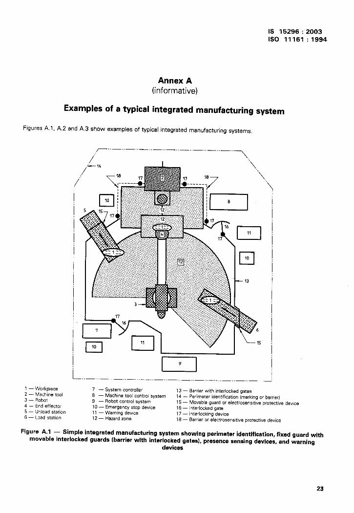
IS 15296:2003
ISO 11161 :1994
of a typical
Annex A(informative)
integrated manufacturing system
Figures A.1, A.2 and A.3 show examples of typical integrated manufacturing systems.
,-.. —.. —.. — ..—.. — .._.. _ .._.. _ ..
/’ >,
1 — Workpiece2 — Machine tool3 — Robot
4 — End effecter5 — Unload station6 — Load station
‘\.\
“\
m11
•110- 13
D—..—..—..—..—..—..—.._.._.._.._.._..—.. _ .._ —
7 — System controller 13 — Berrier with interlocked sates8 — Machine tool control system
~. ---14 — Perimeter identification (marking or barrier)
9 — Robot control system 15 — Movable guard or electrosensitive protective device10 — Emergency stop device 16 — Interlocked gate11 — Warning device 17 — Interlocking device12 — Hazard zone 18 — Barrier or electrosenaitive protective device
Figure A. 1 — Simple integrated manufacturing system showing perimeter identification, fixed guard withmovable interlocked guards (barrier with interlocked gates), presence sensing devices, and warning
-devices
23

IS 15296:2003
ISO 11161 : 1994
“’’et-x I i I (
Section of system-’l
Comolete svstern
Figure A.2 — Complete system, section of system and machines
24
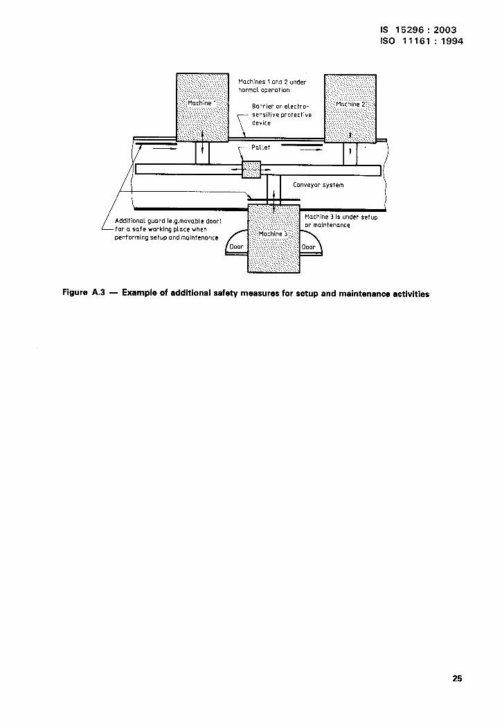
IS 15296:2003
ISO 11161 : 1994
Figure A.3 — Example of additional safety measures for setup and maintenance activities
25
Bureau of Indian Standarxls
BIS is a statutory institution established under the Bureau of /ndian Standards Act, 1986 to promote
harmonious development of the activities of standardization, marking and quality certification of
goods and attending to connected matters in the country.
Copyright
BIS has the copyright of all its publications. No part of these publications may be reproduced in any
form without the prior permission in writing of BIS. This does not preclude the free use, in the course
of implementing the standard, of necessary details, such as symbols and sizes, type or grade
designations. Enquiries relating to copyright be addressed to the Director (Publication), BIS.
Review of Indian Standards
Amendments are issued to standards as the need arises on the basis of comments. Standards are also
reviewed periodically; a standard along with amendments is reaffirmed when such review indicates that
no changes are needed; if the review indicates that changes are needed, it is taken up for revision.
Users of Indian Standards should ascertain that they are in possession of the latest amendments or
edition by referring to the latest issue of ‘BIS Catalogue’ and ‘Standards: Monthly Additions’.
This Indian Standard has been developed from Dot: No. BP 18 (0302).
Amendments Issued Since Publication
Amend No. Date of Issue Text Affected
BUREAU OF INDIAN STANDARDS
Headquarters:
Manak Bhavan, 9 Bahadur Shah Zafar Marg, New Delhi 110002 Telegrams: ManaksansthaTelephones: 3230131, 3233375, 3239402 (Common to all offices)
Regional Offices: Telephone
Central :
Eastern :
Northern :
Southern :
Western
Branches :
Manak Bhavan, 9 Bahadur Shah Zafar Marg 3237617, 3233841
NEW DELHI 110002
1/1 4 C.I.T. Scheme WI M, V.I.P. Road, Kankurgachi(
3378499, 337 &5 61
KOLKATA 700054 3378626,3379120
SCO 335-336, Sector 34-A, CHANDIGARH 160022
{
603843
602025
C.I.T. Campus, IV Cross Road, CHENNAI 600113{
2541216,2541442
2542519,2541315
Manakalaya, E9 MlDC, Marol, Andheri (East)
{
832.9295, 8327858
MUM13AI 400093 8327891,8327892
AHMEDABAD. BANGALORE. BHOPAL. BHUBANESHWAR. COIMBATORE. FARIDABAD.
GHAZIABAD. GUWAHATI. HYDERABAD. JAIPUR. KANPUR. LUCKNOW. NAGPUR.
NALAGARH. PATNA. PUNE. RAJKOT. THIRUVANANTHAPURAM. VISAKHAPATNAM.
Printed at Simco Print\ng Press, Delhi