is 1448-20 (1998): methods of test for petroleum and its ... · 5 apparatus 5.1 the apparatus to be...
TRANSCRIPT

Disclosure to Promote the Right To Information
Whereas the Parliament of India has set out to provide a practical regime of right to information for citizens to secure access to information under the control of public authorities, in order to promote transparency and accountability in the working of every public authority, and whereas the attached publication of the Bureau of Indian Standards is of particular interest to the public, particularly disadvantaged communities and those engaged in the pursuit of education and knowledge, the attached public safety standard is made available to promote the timely dissemination of this information in an accurate manner to the public.
इंटरनेट मानक
“!ान $ एक न' भारत का +नम-ण”Satyanarayan Gangaram Pitroda
“Invent a New India Using Knowledge”
“प0रा1 को छोड न' 5 तरफ”Jawaharlal Nehru
“Step Out From the Old to the New”
“जान1 का अ+धकार, जी1 का अ+धकार”Mazdoor Kisan Shakti Sangathan
“The Right to Information, The Right to Live”
“!ान एक ऐसा खजाना > जो कभी च0राया नहB जा सकता है”Bhartṛhari—Nītiśatakam
“Knowledge is such a treasure which cannot be stolen”
“Invent a New India Using Knowledge”
है”ह”ह
IS 1448-20 (1998): Methods of test for petroleum and itsproducts, Part 20: Determination of flash point by Abelapparatus [PCD 1: Methods of Measurement and Test forPetroleum, Petroleum Products and Lubricants]


IS 1448 [P: 20]:1998
Indian Standard
METHODSOFTESTFORPETROLEUMAND ITSPRODUCTS
[P:20]
DETERMINATION OF FLASH POINT BY ABEL APPARATUS
( Second Revision )
ICS 75.080
0 BIS 1998
BUREAU OF INDIAN STANDARDS MANAK BHAVAN, 9 BAHADUR SHAH ZAFAR MARG
NEW DELHI 110002
November 1998 Price Group 5

Methods of h4easurement and Test for Petroleum, Petroleum Products and Lubricants Sectional Committee. PCD 1
FOREWORD
This Indian Standard (Second Revision) was adopted by the Bureau of Indian Standards, after the draft finalized by the Methods of Measurement and Test for Petroleum, Petroleum Products and Lubricants Sectional Committee had been approved by the Petroleum, Coal and Related Products Division Council.
This standard was prepared on the basis of IP 170175 and IP 33159 and subsequently revised in 1982. In this version (second revision), scope has been enlarged and included determination of closed cup flash point of petroleum products and mixtures to ascertain inflammable vapour below 24’C. Positioning and fixing of oil cup, water bath thermometers into thermometer collar and correction of barometer readings to standard temperature have been included.
In reporting the results of a test or analysis made in accordance with this standard, if the final value, observed or calculated, is to be rounded off, it shall be done in accordance with IS 2 : 1960 ‘Rules for rounding off numerical values (revised)‘.

IS1448[P:20]:1998
1 SCOPE
1.1 This method is intended for the determination of closed-cup flash point of petroleum producti, their mixtures and other liquids having flash points between -18°C and 7O’C.
1.2 Two methods, namely, Method A and Method B have been prescribed. Method A is for liquids flashing between -18°C and +18S°C inclusive; and Method B is for liquids flashing between 19°C and 70°C inclusive.
1.3 This method should be used to measure and describe the properties of materials, products, or assemblies in response to heat and flame under controlled laboratory conditions, and should not be used to describe or appraise the fire hazard or fire risk of materials, products or assemblies under actual fire’ conditions. However, results of this test may be used as elements of a fire risk assessment which takes into account of all the factors which are pertinent to an assessment of the fire hazard of a particular end use.
NOTES
1 Flash point is used in shipping, storage, and handling safety regulations as a classification property to define ‘flammable’ and ‘combustible’ materials. Precise definition of the classes is given in each particular regulation.
2 Flash point may indicate the possible presence of highly volatile materials in a relatively non-volatile or non-flammable material.
3 Since the presence of small propottions of highly volatile materials need to be detected, this test shall be the first determination on a received sample.
1.4 This method may involve the use of hazardous samples, other materials, equipment and operations. It does not set out all the actions required to deal with all the safety problems that arise with its usage as a general method for a wide range of samples presented for testing. It is the responsibility of users of this method to determine and follow adequate safety and health practices as are determined by safety at work legislation applicable to the location of usage of the
Indian Standard
METHODSOFTESTFORPETROLEUMAND ITSPRODUCTS
[ P:20]
DETERMINATION OF FLASH POINT BY ABEL APPARATUS
( Second Revision )
method. The following sub-sections are added for guidance purposes only.
1.4.1 Regard should be given to the requirement in the method to use ignition devices and open flames in close proximity to the surfaces of heated flammable or conibustible liquid samples. This generally requires a different safety approach to normal laboratory practice where flammable and combustible liquids are deliberately kept in closed equipment, and also well away from any potential or known ignition sources.
1.4.2 Hazardous samples and other materials may be used in the method for which precautions need to be taken to avoid health hazards by inhalation, absorption through the skin, and other routes. Flash point testing may be called for as a preliminary step to other forms of investigation of health hazards with unknown samples or new preparations.
1.4.3 The temperatures reached at the end of flash point testing may be considerably above ambient, which can enhance the hazard to health. The vapour concentration at or above the flash point with most materials is well above the continuous exposure limits for operator exposure.
1.5 The precision given for the method is only valid for flash points in the range -5’C to 66S’C.
1.6 A procedure for determining the closed-cup flash point of solid petroleum products and mixtures to ascertain whether they give off inflammable vapour below 24’C is also given in Annex A.
2 NORMATIVE REFERENCES
The following Indian Standards contain provisions which, through reference in this text, constitute provisions of this standard. At the time of publication the editions indicated were valid. All standards are subject to revision, and parties to agreements based on this standard are encouraged to investigate the
IS 1448 [ P : 20 ] : 1998
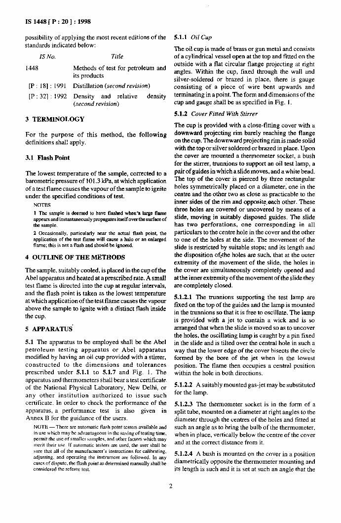
possibility of applying the most recent editions of the
standards indicated below:
IS No.
1448
[P: 181 : 1991
[P : 321 : 1992
Title
Methods of test for petroleum and its products
Distillation (second revision)
Density and relative density (second revision)
3 TERMINOLOGY
For the purpose of this method, the following definitions shall apply.
3.1 Flash Point
The lowest temperature of the sample, corrected to a barometric pressure of 10 1.3 kPa, at which application of a test flame causes the vapour of the sample to ignite under the specified conditions of test.
NOTES
1 The sample is deemed to have flashed when-a large flame appears and instantaneously propagates itself over the surface of the sample.
2 Occasionally, particularly near the actual flash point, the application of the test flame will cause a halo or an enlarged flame; this is not a flash and should be ignored.
4 OUTLINE OF THE METHODS
The sample, suitably cooled, is placed in the cup of the Abel apparatus and heated at a prescribed rate. A small test flame is directed into the cup at regular intervals, and the flash point is taken as the lowest temperature at which application of the test flame causes the vapour above the sample to ignite with a distinct flash inside the cup.
5 APPARATUS
5.1 The apparatus to be employed shall be the Abel petroleum testing apparatus or Abel apparatus modified by having an oil cup provided with a stirrer, constructed to the dimensions and tolerances prescribed under 5.1.1 to 51.7 and Fig. 1. The apparatus and thermometers shall bear a test certificate of the National Physical Laboratory, New Delhi, or any other institution authorized to issue such certificate. In order to check the performance of the apparatus, a performance test is also given in Annex B for the guidance of the users.
NOTE - There are automatic flash point testers available and in use which may he advantageous in the saving of testing time, permit the use of smaller samples, and other factors which may merit their use. If automatic testers are used, the user shall be sure that all of the manufacturer’s instructions for calibrating, adjusting, and operating the instrument are followed. In any cases of dispute, the flash point as determined manually shall be considered the referee test.
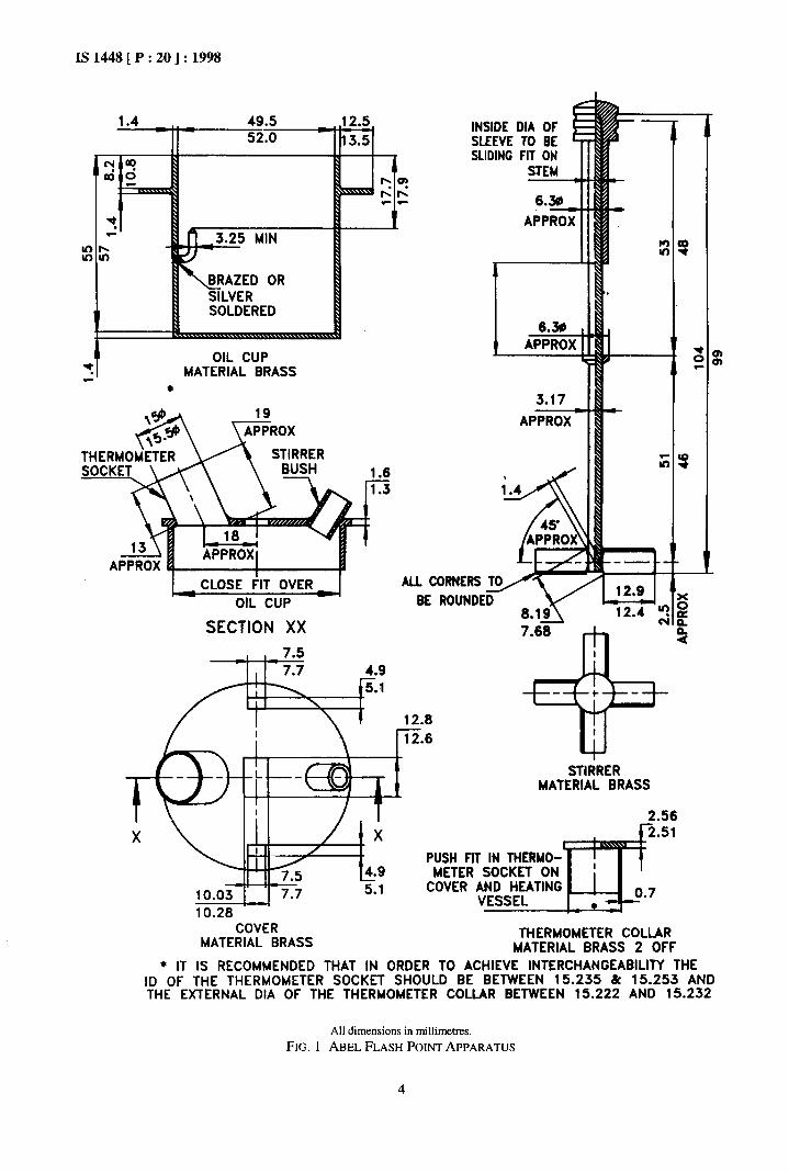
51.1 Oil Cup
The oil cup is made of brass or gun metal and consists of a cylindrical vessel open at the top and fitted on the outside with a flat circular flange projecting at right angles. Within the cup, fixed through the wall and silver-soldered or brazed in place, there is gauge consisting of a piece of wire bent upwards and terminating in a point. The form and dimensions of the cup and gauge shall be as specified in Fig. 1.
5.1.2 Cover Fitted With Stirrer
The cup is provided with a close-fitting cover with a downward projecting rim barely reaching the flange on the cup. The downward projecting rim is made solid with the top or silver soldered or brazed in place. Upon the cover are mounted a thermometer socket, a bush for the stirrer, trunnions to support an oil test lamp, a pair of guides in which a slide moves, and a white bead. The top of the cover is pierced by three rectangular holes symmetrically placed on a diameter, one in the centre and the other two as close as practicable to the inner sides of the rim and opposite each other. These three holes are covered or uncovered by means of a slide, moving in suitably disposed guides. The slide has two perforations, one corresponding in all particulars to the centre hole in the cover and the other to one of the holes at the side. The movement of the slide is restricted by suitable stops; and its length and the disposition of$he holes are such, that at the outer extremity of the movement of the slide, the holes in the cover are simultaneously completely opened and at the inner extremity of the movement of the slide they are completely closed.
5.1.2.1 The trunnions supporting the test lamp are fixed on the top of the guides and the lamp is mounted in the trunnions so that it is free to oscillate. The lamp is provided with a jet to contain a wick and is so arranged that when the slide is moved so as to uncover the holes, the oscillating lamp is caught by a pin fixed in the slide and is tilted over the central hole in such a way that the lower edge of the cover bisects the circle formed by the bore of the jet when in the lowest position. The flame then occupies a central position within the hole in both directions.
5.1.2.2 A suitably mounted gas-jet may be substituted for the lamp.
5.1.2.3 The thermometer socket is in the form of a split tube, mounted on a diameter at right angles to the diameter through the centres of the holes and fitted at such an angle as to bring the bulb of the thermometer, when in place, vertically below the centre of the cover and at the correct distance from it.
5.1.2.4 A bush is mounted on the cover in a position diametrically opposite the thermometer mounting and its length is such and it is set at such an angle that the
2

IS1448[P:20]:1998
stirrer rod clears the oil-level gauge and the blades operate below the level of and without fouling the thermometer bulb. The bush is placed as near as practicable to the outer edge of the cover.
5.1.2.5 A white bead, the dimensions of which represent the size of test flame to be used, is mounted in a visible position on the cover.
5.1.2.6 All parts excepting beads, shall be made of brass or gunmetal; bead shall be made of ivory or other suitable material.
5.1.2.7 Stirrer
pipe also communicate with the water space, through the top plate and two loop handles are provided thereon.
5.1.3.3 The bath rests upon a cast-iron tripod stand, to the ring of which is attached a cylindrical copperjacket not less than 0.559 mm flanged inwards at the top and of such dimensions that the bath, while resting firmly on the iron ring, just touches with its outward projecting flange the inward-turned flange of the jacket.
5.1.3.4 Two handles are provided on the outer jacket. The diameter of the outer jacket is 162 to 167 mm.
It is made of brass or gun metal, and consists of a round stem having four blades or vanes silver soldered in
5.1.3.5 The bath may also be provided with a rotating
place at one end. A collar is fixed MI the stem so that stirrer if d&red, either or both stirrers may be operated
when the stem is inserted into the bush from below, it’ mechanically, if desired. The dimensions of the bath
is arrested at a position such that the correct length are shown in Fig. 2.
protrudes into the oil cup. The top end of the stem is 5.14 Spirit Lamp reduced and screwed. A long sleeve having an internally screwed, knurled knob soldered to its upper
A spirit lamp is provided for raising the temperature
end, is passed over the upper end of the stem and of the water bath;however, any other suitable means,
screwed home. The length of the sleeve is such that a for example, gas -or electrical heating, may be
flat-faced collar at its lower end just comes into contact employed for this purpose.
with the upper end of the bush, leaving the stirrer free 51.5 Thermometers to rotate without appreciable vertical, play. A flat-headed cylindrical plug is provided for insertion
Two thermometers are provided, one for the oil cup
in the bush when the stirrer is not in use. and another for the water bath, conforming to the following specifications:
5.1.2.8 The design and dimensions of the cover and Oil” Water Bath” stirrer are also shown in Fig. 1. The blades of the stirrer shall be set so that the liquid is thrust in a downward
Range -3sT to +70°c -30° c to +80°C
direction when the stirrer is rotated clockwise. Immersion, mm 61 89 Graduation 0.5Oc 0.5Oc
5.1.3 Heating Vessel
The heating vessel or bath consists of two flat-bottomed cylindrical copper vessels placed coaxially, one inside the other, and soldered at their tops to a flat copper ring, greater in outside diameter than the larger vessel and of smaller inside diameter than the smaller vessel. The space between the two vessels is thus totally enclosed and is used as a water jacket. The form and dimensions of heating vessel are shown in Fig. 2.
5.1.3.1 An eboniteor fibrering of right-angled section is fitted into the hole in the centre of the flat ring forming the top of the bath. When the apparatus is in use, the oil cup fits into, and its flange rests upon, this ebonite or fibre ring so that the oil cup is centrally disposed within the heating vessel. The ebonite or fibre ring is secured in place by means of six small screws having their heads sunk below the surface of the ring, to avoid metallic contact between the bath and the oil cup.
Longer lines at each l°C and S°C l°C and 5’C Figured at each 5Oc 5°C Maximum line width, mm 0.15 0.15
Overall length, mm 300 to 320 300 to 320
Length of scale range, 195 164
mm, Min
Bulb, length, mm 7.5 to 10.5 7.5 to 10.5
Bulb, diameter Not greater than Not greater than stem stem
Stem, diameter, mm 6.0 to 7.0 6.0 to 7.0 Distance from bottom 70 to 80 1OOto 111
of bulb to lowest graduation mark, mm
Scale error not to & OS’C below a 0.5”c
exceed O’C, f 0.2’C at
and above 0°C
Expansion chamber, Required Required permit heating to
‘)Thermometen with the lnstitute of Petroleum Design&Ion IP 74C
5.1.3.2 A split socket, similar to that on the cover of conform to these requirements.
the oil cup, but set vertically, allows a thermometer to *)Thermometers with the Institute of Petroleum Designation IP 7SC
be inserted into the water space. A funnel and overflow conform to these requirements.
3
IS 1448 [ P : 20 ] : 1998
I -.-. _.. SOLDERED
OIL CUP MATERIAL BRASS
l
INSIDE DIA OF SLEEVE TO BE SUDING FIT ON
c 6.30 APPROX
OIL CUP
ALL CORNERS TO
SECTION XX
3.17
APG
__- . I Et- 12.9
c 12.4 z
7.60
I
10.28 COVER
MATERIAL BRASS
STIRRER MATERIAL BRASS
2.56
PUSH FIT IN THERMO-
COVER AND HEATING
THERMOMETER COLLAR MATERIAL BRASS 2 OFF
+ IT IS RECOMMENDED THAT IN ORDER TO ACHIEVE INTERCHANGEABILITY THE ID OF THE THERMOMETER SOCKET SHOULD BE BETWEEN 15.235 h 15.253 AND THE EXTERNAL DIA OF THE THERMOMETER COLLAR BETWEEN 15.222 AND 15.232
All dimensions in millimetres.
FIG. 1 ABEL FLASH POINT APPARATUS
4

ISl448[P:20]:1998
SLIDE 0.91mm BRASS
OR TEST OF JET 15
JET AT
LAMP APPROX
EN0
BEAD 3.6-4.1 OF SUITABLE MATERIAL
WHITE
OIL CUP THERMOMETER SECTlON AA
-69.5- 70.5 1 MZ.Zr3.9 LONG CSK SCREWS
$VATER BATH THERMDHLT~R OR ACTUAL POSITION SiL
PLAN VIEW FUNNEL-j 1
INSIDE OIA OF THERMOMETER SOCKET lS.G- 15.0
- OVERFLOW PIPE
-7.0 -12.0 Sz.i-64.9
-EBON’rE OR FIBRE RING (EASY TO FIT ON CAP]
IL3- IL8
L
-STIRRER
\ OUTER JACKET
c-HEATING VESSEL
rid -75-11 IO- - 0.6 THICK COPPER
- 0.6 THICK COPPER
-0.6 THICK COPPER
-_~137-1Lz IO 0 162-187 ID
All dimensions in millimetres.
FIG. 2 ABEL FLASHPOINTAPPARATUS WITHHEATINGJACKET
5

rS1448[P:20]:1998
5.1.6 Other Thermmeters”
Two,low cloud and pour thermometers conforming to the following specification:
Range -80°C to +20°C Immersion, mm 76 Graduation 1°C
Longer lines at each 5°C Figured at each 10°C Maximum line width, mm 0.15
Scale error, Max 1°C down to -33OC 2Oc below -33Oc
Expansion chamber, permit 60°C Total length, mm 225 to 235
Stem OD, mm 6.0 to 8.0 Bulb length, mm 7 to 10 Bulb OD, mm 5.0 Min but nor greater
than stem
Distance from bottom of 90 to 110 bulb to lowest graduation mark, mm
Length of scale range, mm 70 to 100
5.1.6.1 Positioning and fixing of oil cup and water bath the- ters into thermometer collar
a) A diagram of the position of the thermometer stem in the collar is given as Fig. 3. The collar shall be ma& of brass, and shall be of the following dimensions:
Outside diameter Push fit in socket Thickness of tube, mm 0.69 - 0.73 Thickness of flange, mm 2.515 - 2.565
b) The thermometer shall be secured in the collar in the position described in (a), by means of either:
i) a mixture of plaster of Paris and glycerine, or
ii) an epoxy tin based commercial adhesive.
L TUBE PUSH
SHADED AREAS
OF ADHESIVE
FIG. 3 POSITION OF THERMOMETER STEM IN COLLAR
‘)Thermometers with Institute of Petroleum Designation IP 2C conform to these requirements.
5.1.7 Metronome
A metronome is provided, to beat 75 to 80 beats per minute. Alternatively, a pendulum of 60 cm effective length may be used in place of the metronome, counting one beat from one extremity of the swing to the other.
6 PREPARATION OF APPARATUS
Place the test apparatus in position where it is not exposed to droughts.
7 PROCEDURE
7.1 Method A
Liquids flashing between -18’C and + 18.5”C inclusive.
7.1.1 Fill the water bath completely and the air chamber which surrounds the oil cup to a depth of at least 38 mm, with a 50 : 50 mixture of corrosion inhibited ethylene glycol (ethanediol) and water. Cool the bath to -27’C or to at least 9°C below the expected flash point of the material being tested, whichever is higher, measuring the temperature with the thermometer&en in 5.1.6 (see Note). A trial flash point determi”nation shall be carried out if necessary. While cooling, stir the water glycol mixture manually or mechanically or by means of a gentle stream of air introduced into the bath by a tube inserted through the thermometer socket and reaching to the bottom of the bath. Replace the tube by the thermometer (see 5.1.6) when observing the temperature of the bath.
NOTE-When cooling the cup and cover, it is test to use this thermometer. It is an alcohol thermometer, the use of which avoids possible freezing of the mercury in the low flash point themwmeter and consequent ruphllc of the thread.
7.1.2 Cool the sample as received to below 4’C before opening the container. Replace the closure with a cork carrying a thermometer (see 5.1.6). Continue cooling to below -35’C (see Note) 0; to at least 17’C below the expected flash point, whichever is higher. Maintain the sample at this temperature or lower until all flash point tests on the sample are completed.
NPTE- Liquids which crystallize on cooling should be cooled only to just above their crystallizing points.
7.1.3 Place the thermometer (see 5.1.6) in position in the cover of the cup, loosely assemble the cover and cup, and cool until the thermometer registers -35’C or
at least 17’C below the expected flash point, whichever is higher (see Note). Place the cup in position in the bath, which should be on a firm level surface, and replace the thermometer (see 5.1.6) by the oil cup thermometer. Pour in the sample without undue agitation, avoiding as far as possible the formation of air bubbles, until the level just reaches the point of the index gauge on the wall of the cup. Do not move the
apparatus after filling. Place the cover on the cup and push it down into position. Ignite the test flame, adjust
6

its size to approximately 3.8 mm diameter, and maintain it at that size throughout the test, comparing it frequently with the projecting while bead mounted on the cover of the oil cup.
NOTE - Cooling a cover or cup that is wet with dew or melted frost to below 0°C may cause sticking due to ice, for example, sticking of the slide. Wiping the apparatus dry with a duster or a piece of absorbent paper before cooling to below 0°C is usually sufficient to prevent icing, however, alternatively i&g can be prevented by lubricating the outer face of the lip of the cup and the slide with ethylene glycol, glycerol, or a high vacuum silicone lubricant.
7.1.4 Remove the thermometer (see 5.1.6) from the bath and insert the water bath thermometer. Start the metronome beating at 75 to 80 beats per minute and make a single preliminary application of the test flame as described in 7.1.7.
7.1.5 Stir in ‘a clockwise. direction, to give a downward thrust, at approximately 30 rpm or as close to this rate as the viscosity of the material permits. Continue stirring in a steady manner for the duration of the test but do not stir during the application of the test flame.
7.1.6 Apply heat to the outer bath in such a manner that the temperature of the sample in the oil cup rises at the rate of l°C per minute. It may not be possible to keep within the limits until the contents of the cup have warmed to a temperature of -18’C.
NOTE - The rate of temperature rise is best measured over a pe.riod of 5 min over which period the actual temperature rise shall be 5 It 0S”C.
7.1.7 When the temperature of the sample reaches -27’C or at least 9’C below the expected flash point apply the test ‘flame by slowly and uniformly opening the slide in the cover while the metronome beats three times and closing it during the fourth beat.
7.1.8 Apply the test flame in this manner after every OS’C rise in temperature until a distinct flash occurs in the interior of the cup or until a temperature corresponding to a corrected flash point of 18’C is reached. Record the temperature of the sample when the flash occurs and also the barometric pressure in millibars.
7.1.9 The bluish halo which sometimes surrounds the test flame shall not be mistaken for the flash.
7.2 Method B
Liquids flashings between 19°C and 70°C inclusive.
7.2.1 Proceed exactly as given in 7.1.1 except that water may be used in place of the SO : 50 mixture of ethylene glycol and water, and a water bath thermometer may be used in place of the thermometer given in 5.1.6 to observe the temperature of the bath.
IS1448[P:20]:1998
7.2.2 Cool the sample in i& container to at least 17’C below the flash point before opening. Alternatively, cool the sample to below 2’C before opening the container; replace the closure by a cork carrying any of the thermometers and continue cooling until the sample temperature is at least 17’C below the flash point.
7.2.3 Maintain the sample at this temperature or lower, until all flash point tests on the sample are completed (see Note under 9.1.2).
7.2.4 Proceed as give0 in 7.1.3 to 7.1.5, except that the low cloud and pour thermometer may be replaced by oil cup thermometer.
7.2.5 Proceed as given in 7.1.6.
7.2.6 Proceed as given in 7.1.7.
7.2.7. Proceed as given in 7.1.8 until a temperature of 70°C is reached.
8 CALCULATION
a)
b)
Observe and record the barometric pressure at the time of test.
NOTE 1 - The barometric pressure used in this calculation shall be the ambient pressure of the laboratory at the time of test. Many aneroid barometers, such as those used at weather stations and airports, are precorrected to give sea level readings. These shall not be used.
Correct the observed flash point by the follow- ing expression: Corrected flash point = C + 0.25 (101.3-P) where C = observed flash point, “C; and P = barometric pressure, kPa.
NOTE 2 - Where the observed barometric pressure is in other units, the corrections may be made by the following expressions:
Corrected flash point = C + 0.025 (1 01344). or Corrected flash point = C + 0.033 (760-H)
where
M = barometric pressure, mbar; and H = barometric pressure, mmHg.
This correction is applicable over the range 0.98 to 1.05 x 10⁵ N/m2 or 980 to 1.050 mbar.
NOTE 3 - Correction of barometer readings is given in
Annex C.
9 REPORTING
Report the fully corrected result, to the nearest 0.5% as the Abel flash point.
10 PRECISION
Results of duplicate tests shall not differ by more than the following amounts:
Range Repeatability Reproducibility
-5 to 66.W 1°C I .st
7
IS1448[P:20]:1998
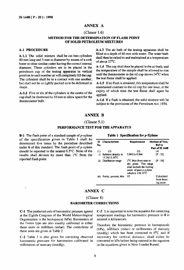
ANNEX A
(Clause 1.6) METHOD FOR THE DETERMINATION OF FLASH POINT
OF SOLID PETROLEUM MIXTURES
A-l PROCEDURE
A-l.1 The solid mixture shall be cut into cylinders 40 mm long and 5 mm in diameter by means of a cork borer or other similar cutter having the correct internal diameter. These cylinders are to be placed in the petroleum cup of the testing apparatus in vertical position in such number as will completely till the cup. The cylinders shall be’in a contact with one another, but shall not be so tightly packed as to be deformed in shape.
A-l.2 Five or six of the cylinders in the centre of the cup shall be shortened to 10 mm to allow space for the thermometer bulb.
A-l.3 The air bath of the testing apparatus shall be filled to a depth of 40 mm with water. The water bath shall then be raised to and maintained at a temperature of about 27’C.
A-l.4 The cup shall then be placed in the air bath, and the temperature of the sample shall be allowed to rise until the thermometer in the oil cup shows 24’C when the test flame shall be applied.
A-1.5 If no flash is obtained, this temperature shall be maintained constant in the oil cup for one hour, at the expiry of which time the test flame shall again be applied.
A-l.6 If a flash is obtained, the solid mixture will be subject to the provisions of the Petroleum Act, 1934.
ANNEX B
(CZuuse 5.1) PERFORMANCE TEST FOR THE APPARATUS
B-l The flash point of a standard sample of p-xylene Table 1 Specification for p-Xylene of the specification given in Table 1 shall be determined five times by the procedure described ii Chsracteristic Requirement Method of Test,
under 6 of this standard. The flash point of p-xylene ’ Ref to
PartofIs144a should be reported to the nearest 0.5”C. None of the (1) (2) (3) (4) results shall deviate by more than l°C from the i) Relative density at 0.860 to 0.866 [P : 321
reported flash point. 15.56i15.5BC ii) Distillation range 2’C Ma* from start to [P : 181
dry point. This range shall include the boiling point of pure p-xylene which is 138.3S°C
iii) Purity, percent, Min 95 Calculated from freez- ing Doint
ANNEX C
(Clause 8) BAROMETER CORRECTIONS
C-I The preferred unit of barometric pressure agreed C-3 It is important to note the equation for correcting at the Eighth Congress of the World Meteorological temperature readings for barometric pressure in 8 is Organization is the hectopascal (hPa). Barometers of entered in kilopascals. the Fortin type are also usually calibrated in either these units or millibars (mbar). The corrections of
Therefore the barometric pressure in hectopascals
these units are given in Table 2. (hPa), millibars (mbar) or millimetres of mercury (mmHg) which has been corrected to O°C and if
C-2 Table 3 is also given for correcting observed necess&y for vertical distance, shall either be barometric pressure for barometers calibrated in converted to kPa before being entered in the equation millimetres of mercury (mmHg). or the equations given in Note 3 under 8 used.
8

IS1448[P
Table 2 Correction of Barometer Readings to Standard Temperature 0°C ( Ch.Lws c- 1 and c-4 )
20 ] : 1998
Temperature, “C
Barometer Reading, hPa or mhar
/ h
\
(11
940
(2)
960
(3)
980
(4)
loo0 (5)
1020
16)
1040
(7)
I 060
(8)
10.0 -1.61 -1.64 -1.68 -1.71 -1.74 -1.77 -1.81
10.5 -1.69 -1.72 -1.76 -1.79 -1.83 -1.86 -1.90
I I.0 -1.77 -1.81 -1.84 -1.88 -1.91 -1.95 -1.99
113 -1.85 -1.89 -1.93 -1.96 -2.00 -2.04 -2.08
12.0 -1.93 -1.97 -2.01 -2.05 -2.09 -2.13 -2.17
12.5 -2.01 -2.05 -2.09 -2.13 -2.18 -2.22 -2.26
13.0 -2.09 -2.13 -2.18 -2.22 -2.26 -2.30 -2.35
13.5 -2.17 -2.22 -2.25 -2.30 -2.35 -2.39 -2.44
14.0 -2.25 -2.30 -2.34 -2.39 -2.44 -2.48 -2.53
14.5 -2.33 -2.38 -2.43 -2.47 -2.52 -2.57 -2.62
15.0 -2.41 -2.46 -2.51 -2.56 -2.61 -2.66 -2.71
IS.5 -2.49 -2.54 -2.59 -2.65 -2.70 -2.75 -2.80
16.0 -2.57 -2.63 -2.68 -2.73 -2.78 -2.83 -2.89
16.5 -2.65 -2.71 -2.76 -2.82 -2.87 -2.92 -2.98
17.0 -2.73 -2.79 -2.84 -2.90 -2.96 -3.01 -3.07
17.5 -2.81 -2.87 -2.93 -2.99 -3.04 -3.10 -3.16
18.0 -2.89 -2.95 -3.01 -3.07 -3.13 -3.19 -3.25
18.5 -2.97 -3.03 -3.10 -3.16 -3.22 -3.28 -3.34
19.0 -3.05 -3.12 -3.18 -3.24 -3.30 -3.36 -3.43
19.5 -3.13 -3.20 -3.26 -3.33 -3.39 -3.45 -3.52
20.0 -3.21 -3.28 -3.35 -3.41 -3.48 -3.54 -3.61
20.5 -3.30 -3.36 -3.43 -3.50 -3.56 -3.63 -3.70
21.0 -3.38 -3.44 -3.51 AS8 -3.65 -3.72 -3.79
21.5 -3.46 -3.53 -3.60 -3.67 -3.14 -3.81 -3.88
22.0 -3.54 -3.61 -3.68 -3.7s -3.82 c3.89 -3796
22.5 -3.62 -3.69 -3.76 -3.83 -3.91 -3.98 4.0.5
23.0 -3.70 -3.77 -3.85 -3.92 -3.99 -4.07 -4.14
23.5 -3.78 -3.85 -3.93 -4.00 -4.08 -4.16 -4.23
24.0 -3.86 -3.93 -4.01 -4.09 -4.17 -4.2s -4.32
24.5 -3.94 -4.02 -4.09 -4.17 -4.25 -4.33 -4.41
25.0 -4.01 -4.10 -4.18 -4.26 -4.34 -4.42 -4.50
25.5 -4.10 -4.18 -4.26 -4.34 -4.43 -4.5 1 -4.59
26.0 -4.18 -4.26 A.34 -4.43 -4.51 -4.60 -4.68
26.5 -4.26 -4.34 -4.43 A.51 -4.60 A.69 -4.17
27.0 -4.34 -4.42 -4.51 -4.60 -4.69 A.77 -4.86
27.5 -4.41 -4.50 -4.59 -4.68 A.77 -4.86 -4.95
28.0 -4.49 -4.59 -4.68 -4.77 -4.86 -4.95 -5.04
28.5 -4.57 -4.67 -4.16 -4.85 -4.95 -5.04 -s.13
29.0 -4.6s -4.75 -4.84 -4.94 -5.03 -S.13 -5 22
29.9 -4.13 -4.83 -4.93 -5.02 -s:12 -5.2 1 -5.31
30.0 -4.81 -491 -5.01 -5.1 I -5.20 -5 30 -5.40

IS 1448 [ P : 20 ] : 1998
Table 3 Correction of Barometer Readings to Standard Temperature O°C ( Clauses C-2 and C-4 )
Temperature
OC
Barometer Read@, hPa or mbar
(1)
700
(2)
720
(3)
740
(4)
760
(5)
780
(6)
800
(7)
820
(a)
840
(9)
860
(10)
880
(11)
10.0 -1.14 -1.17 -1.21 -1.24 -1.27 -1.30 -1.34 -1.37 -1.40 -1.44
10.5 -1.20 -1.23 ;I.27 -1.30 -1.34 -1.37 -1.40 -1.44 -1.47 -1.51
1 I.0 -I .26 -1.29 -I .33 -1.36 -1.40 -1.44 -1.47 -1.51 -1.54 -1.58
11.5 -1.31 -1.35 -1.39 -1.43 -1.46 -1.50 -1.54 -1.58 -1.61 -1.65
12.0 -1.37 -1.41 -1.45 -1.49 -1.53 -1.57 -1.60 -1.64 -1.68 -1.72
12.5 -1.43 -1.47 -1.51 -1.55 -1.59 -1.63 -1.67 -1.71 -1.75 -1.79
13.0 -1.48 -1.53 -1.57 -1.61 -1.65 -1.70 -1.74 -1.78 -1.82 -1.86
13.5 -1.54 -1 sa -1.63 -1.67 -1.72 -1.76 -1.80 -1.85 -1.89 -1.94
14.0 -1.60 -1.64 -1.69 -1.73 -1.78 -1.83 -1.87 -1.92 -1.96 -2.01
14.5 -1.65 -1.70 -1.75 -1.80 -1.84 -1.89 -1.94 -1.98 -2.03 -2.08
IS.0 -1.71 -1.76 -1.81 -1.86 -1.91 -1.96 -2.00 -2.05 -2.10 -2.15
IS.5 -1.77 -1.82 -1.87 -1.92 -1.97 -2.02 -2.07 -2.12 -2.17 -2.22
16.0 -1.82 -1.88 -1.93 -1.98 -2.03 -2.09 -2.14 -2.19 -2.24 -2.29
16.5 -1.88 -1.94 -1.99 -2.04 -2.10 -2.15 -2.20 -2.26 -2.31 -2.37
17.0 -1.94 -1.99 -2.05 -2.10 -2.16 -2.22 -2.27 -2.33 -2.38 -2.44
17.5 -2.00 -2.05 -2.11 -2.17 -2.22 -2.28 -2.34 -2.39 -2.45 -2.51
18.0 -2.05 -2.11 -2.17 -2.23 -2.29 -2.35 -2.40 -2.46 -2.52 -2.58
18.5 -2.11 -2.17 -2.23 -2.29 -2.35 -2.41 -2.47 -2.53 -2.59 -2.65
19.0 -2.17 -2.23 -2.29 -2.35 -2.41 -2.48 -2.54 -2.60 -2.66 -2.72
19.5 -2.22 -2.29 -2.35 -2.41 -2.48 -2.54 -2.60 -2.67 -2.73 -2.79
20.0 -2.28 -2.34 -2.41 -2.47 -2.54 -2.60 -2.67 -2.74 -2.80 -2.87
20.5 -2.34 -2.40 -2.47 -2.54 -2.60 -2.67 -2.74 -2.80 -2.87 -2.94
21.0 -2.39 -2.46 -2.53 -2.60 -2.67 -2.73 -2.80 -2.87 -2.94 -3.01
21.5 -2.45 -2.52 -2.59 -2.66 -2.73 -2.80 -2.87 -2.94 -3.01 -3.08
22.0 -2.51 -2.58 -2.65 -2.72 -2.79 -2.86 -2.94 -3.01 -3.08 -3.15
22.5 -2.56 -2.64 -2.71 -2.78 -2.86 -2.93 -3.00 -3.08 -3.15 -3.22
23.0 -2.62 -2.69 -2.77 -2.84 -2.92 -2.99 -3.07 -3.14 -3.22 -3.29
23.5 -2.68 -2.75 -2.83 -2.91 -2.98 -3.06 -3.14 -3.21 -3.29 -3.36
24.0 -2.73 -2.81 -2.89 -2.97 -3.05 -3.12 -3.20 -3.28 -3.36 -3.44
24.5 -2.79 -2.87 -2.95 -3.03 -3.11 -3.19 -3.27 -3.35 -3.43 -3.51
2.5.0 -2.85 -2.93 -3.01 -3.09 -3.17 -3.25 -3.33 - 3.42 -3.50 -3.58
25.5 -2.90 -2.99 -3.07 -3.15 -3.24 -3.32 -3.40 -3.48 -3.57 -3.65
26.0 -2.96 -3.04 -3.13 -3.21 -3.30 -3.38 -3.47 -3.55 -3.64 -3.72
26.5 -3.02 -3.10 -3.19 -3.28 -3.36 -3.45 -3.53 -3.62 -3.71 -3.79
27.0 -3.07 -3.16 -3.25 -3.34 -3.42 -3.51 -3.60 -3.69 -3.78 -3.86
21.5 -3.13 -3.22 -3.31 -3.40 -3.49 -3.58 -3.67 -3.76 -3.85 -3.93
28.0 -3.19 -3.28 -3.37 -3.46 -3.55 -3.64 -3.73 -3.82 -3.9 I -4.01
28.5 -3.24 -3.34 -3.43 -3.52 -3.61 -3.71 -3.80 -3.89 -3.98 -4.08
29.0 -3.30 -3.39 -3.49 -3.58 -3.68 -3.77 -3.87 -3.96 -4.05 -4.15
29.5 -3.36 -3.45 -3.55 -3.64 -3.74 -3.84 -3.93 -4.03 -4.12 -4.22
30.0 -3.41 -3.51 -3.61 -3.71 -3.80 -3.90 -4.00 -4.10 -4.19 -4.29
C-4 CORRECTION TO O’C C-5 CONVERSIONS TO KILOPASCALS
Read the temperature of the barometer or its Where necessary convert the corrected barometric
immediate area. Enter the temperature into Table 2 or pressure to kilopascals (kPa), using the conversion
Table 3, read off the correction and apply it to the factors given below: observed barometric pressure. kPa = hPa/mbar x IO-’
kPa = mmHg x 0.133 322
10

Bureau of Indian Standards
BIS is a statutory institution established under the Bureau of Indian Standards Act, 1986 to promote harmonious development of the activities of standardization, marking and quality certification of goods and attending to connected matters in the country.
Copyright
BIS has the copyright of all its publications. No part of these publications may be reproduced in any form without the prior permission in writing of BIS. This does not preclude the free use, in the course of implementing the standard, of necessary details, such as symbols and sizes, type or grade designations. Enquiries relating to copyright be addressed to the Director (Publication), BIS.
Review of Indian Standards
Amendments are issued to standards as the need arises on the basis of comments. Standards are also reviewed periodically; a standard along with amendments is reaffirmed when such review indicates that no changes are needed; if the review indicates that changes are needed, it is taken up for revision. Users of Indian Standards should ascertain that they are in possession of the latest amendments or edition by referring to the latest issue of ‘BIS Handbook’ and ‘Standards Monthly Additions’
This Indian Standard has been developed from Dot: No. PCD I( 1482 ).
Amendments Issued Since Publication
Amend No. Date of Issue, Text Affected
Headquarters: BUREAU OF INDIAN STANDARDS
Manak Bhavan, 9 Bahadur Shah Zafar Marg, New Delhi 110002 Telephones: 323 0131,323 33 75,323 94 02
Regional Offices:
Telegrams: Manaksanstha (Common to all officet)
Telephone
Central : Manak Bhavan, 9 Bahadur Shah Zafar Marg NEW DELHI 110002
Eastern :
Nurthern :
l/14 C.I.T. Scheme VII M, V.I.P. Road, Maniktola CALCUTTA 700054
SC0 335-336, Sector 34-A CHANDIGARH 160022
Southern : C.I.T. Campus, IV Cross Road, C!IENNAI 600113
Western :
Branches :
Manakalaya, E9 MIDC, Marol, Andheri (East) MUMBAI 400093
AHMADABAD. BANGALGRE. BHOPAL. BHUBANESHWAR. COIMBATORE. FARIDABAD. GHAZIABAD. GUWAHATI. HYDERABAD. JAIPUR. KANPUR. LUCKNOW. NAGPUR. PATNA. PUNE. THIRUVANANTHAPURAM.
323 76 17,323 38 41
{ 337 84,99,337 85 61 337 86 26,337 9120
{ 60 38 43 60 20 25
{ 235 02 16,235 04142 235 15 19,235 23 15
{ 832 92 95,832 78 58 832 78 91,832 78 92
Printed 8t Simco printina RWI, Delhii India