is 10981 (1983): class of acceptance test for centrifugal
TRANSCRIPT

Disclosure to Promote the Right To Information
Whereas the Parliament of India has set out to provide a practical regime of right to information for citizens to secure access to information under the control of public authorities, in order to promote transparency and accountability in the working of every public authority, and whereas the attached publication of the Bureau of Indian Standards is of particular interest to the public, particularly disadvantaged communities and those engaged in the pursuit of education and knowledge, the attached public safety standard is made available to promote the timely dissemination of this information in an accurate manner to the public.
इंटरनेट मानक
“!ान $ एक न' भारत का +नम-ण”Satyanarayan Gangaram Pitroda
“Invent a New India Using Knowledge”
“प0रा1 को छोड न' 5 तरफ”Jawaharlal Nehru
“Step Out From the Old to the New”
“जान1 का अ+धकार, जी1 का अ+धकार”Mazdoor Kisan Shakti Sangathan
“The Right to Information, The Right to Live”
“!ान एक ऐसा खजाना > जो कभी च0राया नहB जा सकता है”Bhartṛhari—Nītiśatakam
“Knowledge is such a treasure which cannot be stolen”
“Invent a New India Using Knowledge”
है”ह”ह
IS 10981 (1983): Class of acceptance test for centrifugalmixed flow and axial pumps - Class B [MED 20: Pumps]


UDC 621’6711’674 : 620.16 IS:10981 -1983 -- -_--_ __--
Indian Standard
CODE OF ACCEPTANCE TEST
FOR CENTRIFUGAL, MIXED FLOW
AND AXIAL PUMPS-CLASS B
CONTENTS Page
1. Scope . . . . . . . . . 2
2. Symbols . . . . . . . . . 2
3. Terminology . . . . . . . . . 4
4. Guarantees . . . . . . . . . 7
5. Tests . . . . . . . . . 8
6. Procedure for Measurement of Rate of Flow, Head, Speed of Rotation and Power Input 14
7. Cavitation Testing . . . . . . . . . 21
8. Tests on Pumps for Liquids other than Clean Cold Water . . . 25
9. Analysis of Tests . . . . . . . . . 26
Appendix A Pumping Installation Under Non-standard Conditions 28
Appendix B Costs and Repetition of Tests. . . . . . . 29
Appendix C Friction Losses . . . . . . . . . 29
Appendix D Effect of Pre-swirl Induced by the Pumps . . . . . . 33
Appendix E Pump Test Sheet . . . . . . . . . 33
Appendix F Conversion to SI Units . . . . . . 35
Appendix G Check List . . . . . . -.. 36
ixplanatory Note . . . . . . . . . 36
Adopted 9 September 1983 @ March 1985, ISI Gr 12
988”
INDIAN STANDARDS INSTITUTION
MANAK BHAVAN, 9 BAHADUR SHAH ZAFAR MARG
NEW DELHI 110002

IS:10981 - 1983
1. Scope
1.1 Lays down a code for acceptance testing of pumps, defining the terms and quantities that are used, establishing the methods of testing and the ways of measuring the quantities involved according to Class 6, so as to ascertain the performance of the pumps and to compare them with the manufacturer’s guarantee.
1.2 In general this code applies to any size of pumps tested with clean cold water and other liquids behaving as clean cold water such as defined in 8.
1.3 This code is not concerned with the structural details of the pumps nor with the mechanical properties of their components.
1.4 This test code specifies the standard methods of measurement and instruments to be used for the determination of rate of flow, inlet total head, outlet total head, pump total head speed of rotation and pump power input.
2. Symbols - Given in Table 1.
TABLE 1 SYMBOLS
Reference Number in* Relevant
Part of IS : 1890
-
- - - - -
- 3.2.1 .l 3.2.1.2 3.2.3.2 3.2.3.8 3.2.3.6 3.2.3.7
3.2.3.9 3.2.3.10 3.2.3.11 3.2.3.12
3.2.4.1 3.2.4.2 3.2.4.3 3.2.5.1
3.2.5.2 3.2.5.3 3.2.5.4
3.2.6 6.2.1.2
Quantity
Mass
Length
Time
Temperature
Area
Volume Angular velocity
Velocity
Acceleration of free fall
Speed of rotation
Density Gauge pressure Viscosity (dynamic viscosity)
Kinematic viscosity
Energy
Power (general term )
Reynolds number Diameter
Mass rate of flow
Volume rate of flow
Distance to reference plane
Pump total head
Inlet total head
Outlet total head
Specific energy Loss of head at inlet
Loss of head at outlet Net positive suction head
Atmospheric pressure (absolute )
Vapour pressure ( absolute )
Pump power output Pump power input
Motor power input
Pump efficiency
Transmission efficiency
Motor efficiency Overall efficiency
Type number Friction factor
Symbol
m I
f, A V W
V
9
n
P Pe
I( V
E P
Re D
Qm w
;I
HI Hz
Y
Hh Hh (NPSH)*
Pb
P-f:
P&
p&T
qin’t , qmot
rlw K x
Dimensions
M
L
T
0 L” LS
T-1 LT-1 LT-3
T-1 ML-3 ML-IT-2
ML-lT-1
L3T-1 ML”T-3
M L*T-3
pure number L
MT-1 L3T-1
L
L
L L L3T-3
L L
L ML-IT-3
ML-IT-3
M LZT-3
M LBT-3
M LBT-3
pure number
pure number
pure number
pure number
pure number pure number
SI Units
kg m
s “C ma ms
radjs
m/s m/s2 s-1
kg/m3 PS pa-s
ms/s J
W
m
kg/s m3/s m m
m
m
j/kg m
m
m
Pa
Pa W W
W
Note 1 -_M = Mass L = Length T = Time 0 = Temperature.
Note 2 - Where no number is given, reference may be made to various parts of IS : 1890 I Recommendations for quantities and units ‘.
*An optional symbol for net positive suction head is HIT.
2

IS : 10981 - 1983
2.2 Alphabetical Lists of Basic Letters and Subscripts -As given in Tables 2 and 3.
Symbol
A
D
I5
B
H
HI
K
k
I
m
n
( NPSH )
P
P
4m
QV
Re
t
V
V
X
Y
I
r)
0
A
P
V
P
0
TABLE 2 LETTERS USED
Quantity
Area
Diameter
Energy
Acceleration of free fall
Head
Losses in terms of head of liquid
Type number
Absolute roughness
Length
Mass
Speed of rotation
Net positive suction head
Pressure
Power
Mass rate of flow
Volume rate of flow
Reynolds number
Time
Velocity
Volume
Tolerance
Specific energy
Distance to reference plane
Efficiency
Temperature
Friction factor
Dynamic viscosity
Kinematic viscosity
Density
Angular velocity
AS SYMBOLS
SI Units
ms
m
i
m/s*
m
m
pure number
m
m
kg
s-1
m
Pa
W
kg/s
ms/s
pure number
S
m/S
ms
pure number
J/kg
m
pure number
“C
pure number
P&S
me/s
kg/m3
rad/s

IS:10981-1983
TABLE 3 LETTERS AND FIGURES USED AS SUBSCRIPTS
( Clause 2.2 )
Subscript Meaning
0
1
2
a
av
b
e
G
gr
int
i
m
M
mot
P
r
S
sP
t
U
V
value at the specified speed
inlet
outlet
absorbed
available
atmospheric
effective
guaranteed
unit ( overall )
intermediate
loss
1) general case : mean
2) related to 9 : mass
manometric
motor
pump
required
eye
specified*
total
useful
1) general case : vapour
2) related to 9 : volume
*This indication applies to the values of quantities relating to the guarantee point.
3. Terminology
3.1 General- In order to avoid any error of interpretation it has seemed preferable to reproduce here the definitions of quantities and units as given in various parts of IS : 1890 and to supple- ment these definitions by some specific information on their use in this test code.
g- Acceleration of free fall*
n -Speed of rotation : The quotient of the number of rotations by the time.
P -Density : Mass per unit volume.
P - Pressure : The quotient of force by area. Unless otherwise specified, all pressures are gauge pressures (measured with respect to the atmospheric pressure ).
*For Class B tests, the local value of g should be used. Nevertheless, in most cases, a value of 9’81 m/se would not involve significant error.
The local value should be calculated by the formula :
g = 9’806 17 ( 1 - 2’64 x 10-3 cos 2(p + 7 x IO+ cos’J2(p ) - 3,086 x IO-SZ
where ‘p and Z are respectively the latitude and the altitude.
4

IS:10981-1983
p-Viscosity (dynamic viscosity, some times called absolute viscosity) is defined by expression:
UO 7=p---
h
where
u. is the velocity of a flat plate moving in its own plane while keeping parallel to a fixed flat wall;
h is the distance from the flat plate to the fixed flat wall;
7 is the friction force of the fluid on the unit area of the flat plate during its motion.1
Note-h should be small enough to obtain laminar flow of the fluid between the flat plate and the fixed flat wail.
Y - Kinematic viscosity : the quotient of the viscosity ( dynamic viscosity ) by the density :
v = 2 P
P- Power : The quotient of the energy transferred during a time interval by the duration of this interval.
Re- Reynolds number is defined by the expression :
3.2 Definitions Peculiar to the Test Code-The definitions of concepts used in this test code, together with associated symbols, if any have been allocated.
Concepts, even though in current use, which are not strictly necessary to the application of this code are not defined.
3.2.1 Flow rate?
3.2.1.1 om- In this test code, mass rate of flow designates the external mass rate of flow of the pump, that is, the rate of flow discharged into the pipe from the outlet branch of the pump.
Note 1 -The following losses or abstractions inherent to the pump are not to be reckoned in the quantity delivered:
a) Discharge necessary for hydraulic balancing of axial thrust;
b) Cooling of bearings of the pump itself; c) Water seal to the packing; and d) Leakage from the fittings, internal leakage, etc.
Note 2 -On the contrary, if the losses or abstractions as indicated in Note 1 above are taken at a point before the flow measuring section, the following derived quantities should be added to the measured rate of flow :
a) Cooling of motor bearings; and
b) Cooling of gear box, bearing, oil cooler, etc.
3.2.1.2 ov- The outlet volume rate of flow has the following value :
In this test code, this symbol may also designate the volume rate of flow in a given section*; it is the quotient of the mass rate of flow in this section by the density. (The section may be designated by the proposed subscripts. )
3.2.2 Velocity of flow (v) -The mean velocity of flow equal to the volume rate of flow divided by the pipe cross-section* :
9v v =-- A
3.2.3 Head - The energy per unit weight of fluid.
*Attention is drawn to the fact that in this case qv may vary for different reasons across the circuit.
5

IS:10981 - 1983
3.2.3.1 Reference plane - The horizontal plane through the centre of the circle described by the external point of the entrance edges of the impeller blades; in the case of double inlet pumps the plane should be taken through the higher centre.
The manufacturer should indicate the position of this plane with respect to precise reference points on the pump.
3.2.3.2 The difference between the level of the horizontal plane under consideration and the level of the reference plane (z) is :
a) positive, if the plane in question is above the reference plane;
b) negative, I ‘f the plane in question is below the reference plane.
3.2.3.3 Gauge pressure ( PC, ) -The effective pressure, relative to atmospheric pressure, The
head corresponding to this pressure is $. Its value is :
a) positive, if this pressure is greater than the atmospheric pressure;
b) negative, if this pressure is less than the atmospheric pressure.
3.2.3.4 Velocify head-The kinetic energy per unit weight of the liquid in movement. It is expressed by :
P
-2g
where v is the mean velocity of the liquid in the section considered,
3.2.3.5 Total head - In any section, the total head is given by :
z + + + -C- 2g
This is related to atmosphere. The absolute total head in any section is given by :
z+ _P- +_P!L+ y’ Pg Pg 2g
3.2.3.6 /n/ef fofal head ( HI) - The total head in the inlet section of the pump :
3.2.3.7 Outlet total head ( Ha ) - The total head in the outlet section of the pump :
Ha=za+~ +x Pzg 2g
3.2.3.8 Pump fofal head ( H 1 - The algebraic difference between the outlet total head and the inlet total head.
H=Ha-HI
If the variation of density of the pumped liquid is not significant,
If the variation of density of the pumped liquid is significant, p should be replaced by the mean value ( Pm )
Pm= p,+p, 2
3.2.3.9 Specific energy ( Y) - The energy per unit mass of liquid. It is given by the equation
Y=gH
3.2.3.10 Loss of total head af inlet (HII ) - The difference between the total head of the liquid at the measuring point, or possibly of the liquid without velocity in the suction chamber, and the total head of the liquid in the inlet section of the pump.
6
3.2.3.11 Loss of total head on delivery ( Hjr ) - The difference between the total head of the liquid in the outlet section of the pump, and the total head of the liquid at the measuring point.
IS:10981-1983
3.2.3.12 Nef posifive suction head (NPSH) -The total inlet head, pluse the head corresponding to the atmospheric pressure, minus the head corresponding to the vapour pressure:
NPSH=Hl+ 2 -2
Thus NPSH, as well as inlet total head, is referred to the reference plate. It is necessary to make a distinction between:
-the NPSH required at given flow and speed of rotation for a given pump specified by the manufacturer;
-the NPSH available for the same flow determined by the installation;
-the NPSH determined during the cavitation test. This value is that which causes in the first stage a drop of (3+K/2) percent in total head of the first stage or in efficiency at a given rate of flow, or in a rate of flow or efhciency at a given total head.
Subscripts may be used to differentiate these quantities [ for example (NPSH) when the required value is concerned and (NPSH) when the avaiiable value is concerned 1.
3.2.4 Power
3.2.4.1 Pump power oufpuf ( P, ) - The power transferred to the liquid at its passage through the pump:
Pu=qmgH=qmY=pqvgH 3.2.4.2 Pump power input ( Ps ) - The power measured at the pump cooling.
3.2.4.3 Mofor power input ( Pgr ) - The power absorbed by the pump driver.
3.2.5 Efficiency
3.2.5.1
3.2.5.2
3.2.5.3
3.2.5.4
pump power output pump efficiency (7 1 = pump power input
pump power input Transmission efficiency (shafting, coupling, gears, etc 1 ( rlht 1 = power at motor s,.,aft
Motor efficiency ( ?mot ) - power at motor shaft
motor power input
Overall efficiency ( 7gr 1 = ( r )vnt Ylmot = pump power output
motor power input
3.2.6 Type number K - The type number, a formula*:
K=
where qlp is the volume rate of flow per eye,
H’ is the head per stage.
dimensionless quantity, is defined by the following
27~ n ( 4’v Is
w-d
and
Note - Attention is drawn to the fact that, in this standard, the type number applies to the guaranteed flow rate, which is not in conformity with common practice whare K is calculated from the flow rate corresponding to the maximum efficiency.
3.2.7 Oscillations - Short-period fluctuations about a mean value during the time that a single reading is being made.
3.2.6 Variafions - Those changes in value which take place between one reading and the next.
4. Guarantees
4.1 Subjects of Guarantees - One or more of the following quantities may be guaranteed by the manufacturer under the specified conditions and speed of rotation:
a) total head of the pump ( HG ), at the agreed flow rate qvo, or flow rate of the pump qvg at the agreed total head Ho ( see 9,4.1 );
WQ’V a *This formula is the same as the bask formula K = - .
YR2
7

IS : 10981 - 1983
b) power input or efficiency of the pump or combined pump-motor unit at guaranteed greHG point;
c) NPSH required by the pump at the agreed flow rate gvo;
d) other points of the gvH curve may be indicated by guaranteeing the total head at a reduced or increased flow rate, in which case separately agreed increased tolerances will apply.
4.2 Ofher Condifions for Guarantee - Unless otherwise specified in the contract, it shall be taken that the following conditions apply to the guarantee values:
a) unless the chemical and physical properties of the liquid are stated, it shall be taken that the guarantee points apply to clean cold water;
b) the relation between the guarantee values under clean cold water conditions and the likely performance under other liquid conditions shall be agreed in the contract;
c) guarantees shall apply only to the pump as tested by the methods and in the test arrange- ments specified, in this standard; and
d) the pump manufacturer shall not be responsible for the specification of the guarantee point.
4.3 Fulfilmenf of Guarantee - The nominated guarantee for any quantity shall be deemed to have been met if, when tested according to this standard, the measured performance falls within the tolerance specified in 9 for the particular quantity. Other points on the Q& curve shall not be guaranteed unless the points and tolerances for fulfilment of guarantee are agreed in the contract.
5. Tests
5.1 Organization of Tesfs
5.1.1 P/ace of testing - Acceptance tests shall be carried out at the manufacturer’s works, or alternatively at a place to be mutually agreed between the manufacturer and the purchaser.
5.1.2 Time of testing - The time of testing shall be mutually agreed by the manufacturer and the purchaser.
When tests are not carried out in the manufacturer’s works, time shall be allowed for pre- liminary adjustments by both the manufacturer and the installer.
5.1.3 Staff - Accurate measurements depend not only on the quality of the measuring instru- ments used but also on the ability and skill of the persons operating and reading the measuring devices during the tests. The staff entrusted with effecting the measurements should be selected just as carefully as the instruments to be used in the test.
Specialists with adequate experience in measuring operations in general shall be charged with operating and reading complicated measuring apparatus. Reading simple measuring devices may be entrusted to such helpers who, upon short prior instruction, can be assumed to effect the readings with proper care and the accuracy required.
A chief of tests possessing adequate experience in measuring operations shall be appointed, Normally, when the test is carried out at the manufacturer’s works, the chief of tests is a staff member of the manufacturing firm. _
All persans charged with effecting the measurements are subordinated during the tests to the chief of tests, who conducts and supervises the measurement, reports on test conditions and the results of the tests and then drafts the test report. All questions arising in connection with the measurements and their execution are subject to his decision.
The parties concerned shall provide all assistance that thechief of tests considers necessary.
51.4 Test programme - Only the guaranteed operational data shall form the basis of the test; other data determined by measurement during the tests shall have merely an indicative ( informative ) function and it shall be so stated if they are included in the programme.
5.1.5 Testing equipment - The chief of tests shall be responsible for the selection and operation of measuring equipment. All of the measuring equimpent shall be covered by reports showing, by calibration or by comparison with other relevant Indian Standards, that it complies with the requirements of accuracy of measurements given in 5.4, These reports shall be presented, if required.
5.1.6 Tesf reporfs - All test records and record charts shall be initialled by the chief of tests and by the representatives of both the purchaser and the manufacturer, each of whom shall be provided with a copy of all records and charts.
8

IS : 10981.1983
The evaluation of the test results, including graphical plotting of the pump perfomance curve, shall be made as far as possible while the tests are in progress and, in any case, before the installation and instrumentation are dismantled in order that suspect measurements can be repeated without delay.
5.2 Test Arrangements ( see Appendix A )
5.2.1 Standard test arrangements - All practical steps shall be taken to ensure that flow through the measuring section shall result in:
a) an axially symmetric velocity distribution;
b) a uniform static pressure distribution; and
c) freedom from swirl induced by the installation.
Some methods for ensuring these conditions for standard test arrangements are suggested below.
Acceptance tests may be carried out under standard test conditions for pumps where the type’ number is less than or equal to 1’5.
When the type number is greater than 1.5, it shall be agreed contractually that the results of such tests will be held to apply only to specified conditions. The purpose of such tests will be to provide an assurance that the pump will, if suitably installed, perform the specified duty.
It is recommended that for standard test circuits leading from reservoirs with a free surface or from large stilling vessels in a closed circuit, the inlet straight length L shall be determined by the expression:
L ---K-j-5 D
where D is the pipe diameter.
This expression is also valid for an arrangement that includes, at a distance L upstream, a simple medium-radius right angle bend that is not fitted with guide vanes. Under these conditions, flow straighteners are not necessary in the pipe between the bend and the pump.
However, in a closed circuit where there is neither a reservoir nor a stilling vessel immediately upstream of the pump, it is necessary to ensure that the flow into the pump is free from swirl induced by the installation and has a normal symmetrical velocity distribution.
Significant swirl can be avoided by:
a) careful design of the test circuit upstream of the measurement section;
b) judicious use of a flow straightener; and
c) suitable arrangement of the pressure tappings to minimize their influence on tha measurement.
5.2.:! Simulated test arrangements - When pumps are tested under simulated site conditions, flow straighteners shall not be installed immediately before the pump. It is important that the characteristics of flow to the simulated circuit should be controlled; that the flow should, as far as possible, be free from significant swirl induced by the installation and have a symmetrical velocity distribution. If necessary, the velocity distribution of the flow into the simulated circuit shall be determined by careful pitot tube traverse, in order to establish that the required flow characteristics exist; if not, the required characteristics can be obtained by the installation of suitable means, such as the Zanker flow straightener ( Fig. 1 ); care shall be taken to ensure that the conditions of test will not be affected by the high, irrecoverable pressure lcsses associated with efficient straightening devices.
5.2.3 Pumps tested with fittings - If specified in the contract, standard tests can be carried out on a combination of a pump, and
a) associated fittings at the final site installation;
b) an exact reproduction thereof: or
c) fittings introduced for testing purposes and taken as forming part of the pump itself ( see 5.2.4 to 5.2.6 ).
Connection on the inlet and outlet sides of the whole combination shall be made in accordance with 6.2.2.
9


IS:10981 -1983
Measurements shall then be taken in accordance with 5.3.2.2 and 5.3.2.3.
5.2.4 Pumping installation under submerged conditions - Where a pump, or a combination of a pump and its fittings, is tested or installed in conditions where the standard pipe connection on either inlet or outlet as described in 6.2.2 cannot be made owing to inaccessibility oi submergence, measurements shall be taken in accordance with 6.2.1.6.
5.2.5 Borehole and deep well pumps - Borehole and deep well pumps cannot usually be tested with their complete lengths of delivery main and consequently the loss of head in the portions omitted; therefore the power absorbed by any shafting therein cannot be measured. Any thrust bearing would also be more lightly loaded during the test than it would be in the final installation ( see 6.2.1.6 ).
5.2.6 Self-priming pumps - In principle the priming ability of self-priming pumps shall always be verified at the contractual static suction head with the attached inlet piping equivalent to that in the final installation. When the test cannot be carried out in the described manner, the test arrangement to be used shall be specified in the contract.
5.3 Test Conditions
5.3.1 Execution of tests - The duration of the test shall be sufficient to obtain consistent results having regard to the degree of accuracy to be achieved.
Where multiple readings are taken to reduce the error margin ( see 5.3.2 ), they shall be taken at unequal intervals of time.
All measurements shall be made under steady conditions of operation but a decision to make measurements when such conditions cannot be obtained shall be a matter of agrsement between the parties concerned.
Verification of the guaranteed point shall be obtained by recording at least five points of measurements closely and evenly grouped around the guaranteed point, for example between 0.9 and 1’1 gva.
Where, for special reasons, it is necessary to determine performance over a range of operating conditions, a sufficient number of measurements points shall be taken to establish the performance within the limits of error stated in 5.4 ( see also Appendix B ).
5.3.2 Stability of operation
5.3.2.1 Permissible oscillations in readings and use of damping - Where the construction or operation of a pump is such that oscillations of great amplitude are present, measurements may be carried out by means of an instrument capable of providing an integration over at least one complete cycle of oscillation. The calibration of such an instrument shall comply with the provisions of the appropriate clauses.
5.3.2.2 Restricted damping may be introduced in measuring instruments and their connecting lines where necessary to reduce the amplitude of oscillations to within the values given in Table 4.
TABLE 4 MAXIMUM PERMISSIBLE AMPLITUDE OF SPECIFICATIONS AS A PERCENTAGE OF MEAN VALUE OF QUANTITY BEING MEASURED
( Clauses 5.3.2.1 and 5.3.2.3.1 )
Measured Quantity
Rate of flow 7
Maximum Permisslbie Amplitude of Oscillations
Head Torque Power J Speed of rotation
f 3 percent
It1
Note 1 -When using a differential pressure device to measure flow rate, the maximum permissible amplitude of the oscillations of the observed differential head may be 6 percent.
Note 2 -In the case of inlet total pressure head and outlet total pressure head measurement, the maximum permissible amplitude oscillation is to be calculated individually on the pump total head.
Where it is possible that damping will significantly affect the accuracy of the readings, the tests shall be repeated using a symmetrical and linear damping device, for example a capillary tube.
11

IS : 10981. 1983
5.3.2.3 Number of sets of observations
5.3.2.3.1 Steady conditions - In steady and well controlled test conditions, only one set of readings of individual quantities will be recorded for the specified test conditions. This set shall be recorded only after the observers have been satisfied that the oscillations have settled down within the limits specified in Tables 4 and 5.
5.3.2.3.2 Unsteady conditions - In such cases where the unsteadiness of test conditions gives rise to doubts concerning the accuracy of the tests, the following procedure shall be followed.
Repeated readings of the measurements shall be made at the guaranteed point, only speed and temperature being allowed to be controlled. Throttle valve water level, gland, balance water, settings, etc, shall be left completely unaltered. The difference between these repeated readings of the same quantities will be a measure of the unsteadiness of the test conditions, which are at least partly influenced by the pump under test as well as the installation.
A minimum of three sets of readings shall be taken at the guaranteed point and the value of each separate reading and of the efficiency derived from each set of readings shall be recorded. The percentage difference between the largest and smallest values of each quantity shall not be greater than that given in Table 5. It will be noted that a wider tolerance is permited if the number of readings is increased up to the maximum requirement of nine readings.
These tolerances are designed to ensure that the errors due to scatter, taken together with the systematic error limits given in Table 6, will result in overall measurement errors not greater than those given in Table 7.
TABLE 5 LIMITS OF VARIATION BETWEEN REPEATED MEASUREMENTS OF THE SAME QUALITY ( BASED ON 95 PERCENT CONFIDENCE LIMITS )
Number of Sets of Maximum Permissible Difference Between Largest and Readings Smallest Readings of Each Quantity, Percent
--- A--_-----~ Rate of Flow Head
Torque Power Speed of Rotation
3 0’8 0’25
5 1.6 0’5
7 2-2 0’7
9 2.8 0’9
The arithmetic mean of all the readings for each quantity shall be taken as the actual value for the purposes of the test.
If the values given in Table 5 cannot be reached, the cause shall be ascertained, the conditions rectified and a new complete set of readings made, that is, all the readings in the original set shall be rejected. No reading(s) in the set of observations may be rejected because it lies outside the limits.
In the case where the excessive variation is not due to procedure or instrumentation errors, and cannot therefore be eliminated, the limits of error may be calculated by statistical analysis.
5.3.3 Speed of rotation during test ( see 4.1 ) -The difference between the specified speed of rotation and the test speed of rotation may be expressed as a percentage as follows:.
( n-nllp >
x 100 nap
This shall be within the following limits.
5.3.3.1 For flow rate and head - From 2:: percent of the specified value.
5.3.3.2 For pump efficiency - From f 20 percent of the specified value.
For a combined motor-pump unit, the motor efficiency change between specified and test speeds, shall be established at the time of agreeing the contract.
The lower speeds are also acceptable. The following formula for efficiency correction shall be applied:
* -Ei
where
‘11 = efficiency at actual speed,
12

IS : 10981-1983
ne - efficiency at specified speed, Ne - specified speed, N1 - actual test speed, and n = exponent established by test data, its value of exponent is 0’17.
5.3.3.3 For ( NPSH ) fesfs - From f 20 percent provided that the pump flow rate during the test lies within 0.50 and 1’20 of the flow rate corresponding to the maximum eficiency,
Note -For tests conforming to the requirements of 7.1.1.1, the variation mentioned in 5.3.3.3 may always be allowed. For tests conforming to the requirements of 7.1.1.2, it may be allowed for pumps with type numbers less than or equal to 2; for pumps with type numbers greater than 2, agreement between the parties concerned is required.
5.3.4 Control of head - The test conditions may be obtained, among other methods, by throttling in either or both the inlet and outlet pipes. When throttling in the inlet pipe is used, due consideration shall be given to the possibility of cavitation or of air coming out of the water, which might affect the operation of the pump ( see 7.1.2 ) the flow measuring device ( see 6.1.3 ) or both.
5.4 Accuracy of Measurement - The limits of measurement errors laid down in this standard are those which refer to measurements taken and to quantities calculated therefrom; they apply to the maximum permissible discripanciesbe tween measured and actual performance ( see 9.4 ).
For the purpose of this standard, the tolerance on the measurement of a variable is defined as twice the standard deviation of this variable. The tolerance shall be calculated and indicated as such for any mea,surement in accordance with this standard.
When partial errors constituting the tolerance are independent one from the other, are small and numerous, and have a gaussian distribution, there is 95 percent probability that the true error is less than the tolerance.
Any device or method which by calibration or comparison has been- demonstrated to be capable of measuring with systematic errors not exceeding the limits given in Table 7 may be used. The devices or methods shall be agreed upon by both the parties concerned.
If the recommendations concerning the systematic errors of instruments as given in Table 6 and those concerning the actual test procedure are followed, it shall be assumed that the overall limits of error will not exceed those given below.
TABLE 6 PERMISSIBLE SYSTEMATIC ERRORS OF MEASURING INSTRUMENTS
( Clauses 5.3.2.3.2 and 5.4 )
Measured Quantity Permissible Limit, percent
Rate of flow f 1’5
Pump total head Pump power input 1 Electrical power input ,>
f 1’0
( for overall efficiency tests ) J
Speed of rotation f 0’35
TABLE 7 MAXIMUM LIMITS OF OVERALL ERROR ( Clauses 5.3.2.3.2 and 5.4 )
Quantity
Rate of flow
Pump total head 1
Pump power input
E.lectrical power input (for overall efficiency tests ) 1
Speed of rotation
Overall efficiency ( computed from the rate of flow, total head and electrical power )
Pump efficiency
Permissible Limit, percent
f 2.0
f 1’5
f 0’5
i 2’5
f 2%
13

IS: 10981-1983
6. Procedure for Measurement of Rate of Flow, Head, Speed of Rotation and Power Input 6.1 Measurement of Flow Rate
6.1.1 Weighing tank method - This method is capable only of measuring the mean values of flow rate during the period concerned.
It is subject to the errors of the weighing, of. the time-measuring apparatus employed, of time taken for the diversion of the flow into and from the weighing tank and those involved in determination of density.
the
the the
Note - In the case where two tanks are used alternately during the measuring period, the flow being diverted from one to the other, only the times of initial diversion into and final diversion from the measuring system are to be taken into account, not the times of the intermediate diversions from tank to tank.
6.1.2 Volumetric tank method - This method, as in the case of the weighing method, is only capable of measuring the mean value of the flow rate during the period concerned.
In every case a leakage test of the tank shall be carried out and correction made for leakage, if necessary. Where possible, initial calibration shall be carried out by weighing a liquid of known density into the measuring tank. Outdoor tanks should be adequately sheltered so that the level and the level-measuring devices are not disturbed by wind or rain.
In the case of big outdoor tanks the method is in general subject to errors in measurement of levels which are not stationary and which may be non-uniform. In such a case the levels shall be simultaneously measured within stilling tubes, at not fewer than four widely-separated positions within the tank.
Water levels may be measured with hook gauges, float gauges, piezometer or other instr uments capable of maintaining the required accuracy.
6.1.3 Orifice plates, venturi tubes and nozzles - The measurement of flow rate may be carried out using devices designed and installed in accordance with relevant part of IS : 2952 ‘ Recommendation for methods of measurement of fluid flow by means of orifice plate and nozzles ’ for orifice plates and nozzles and relevant part of IS : 4477 ‘ Method of measurement of fluid flow by means of venturimeters ’ for venturi tubes. Minimum straight lengths required upstream from the pressure difference device, especially, are given in Table 1 of IS : 2952 ( Part 1 )-I964 in the case of orifice plates and nozzles and in Table 1 of IS : 4477 ( Part 1 )-I967 in the case of venturi tubes. For the purpose of this standard the pump will be considered to cause a flow disturbance equivalent to a single 90” bend lying in the same plane as the pump volute or the last stage of a multistage pump or the outlet bend of the pump.
Care shall be taken to ensure that neither cavitation, nor air is present in the flow measuring devices. Special care should be taken to ensure that the indications of the device are not affected by air coming out of solution at the control valve. The presence of air can usually be detected by operating the air vents on the measuring device.
It shall be possible at any moment to check the equipment for differential pressure measurement using liquid column or dead weight manometers.
6.1.4 Other flow measurement devices-Some other methods, such as electromagnetic flowmeters or ultrasounds, etc, may be used only after mutual agreement between the parties conerned on the installation conditions and obtainable accuracy.
6.2 Measurement of Head
6.2.1 Pump total head
6.2.1.1 The pump total head is calculated in accordance with the definition given in 3.2.3.6. However, in certain cases the pump total head may be measured using one differential pressure device.
This type of installation and the corresponding formulae are given in Fig. 6.
When this is deemed preferable, the pump total head may be replaced by an expression giving the increase in specific energy of the fluid conveyed by the pump ( Y = gH, see 3.2.3.9 ).
The ‘ specific energy ’ increase is obtained by multiplying both sides of the pump total head equation given above by g.
6.2.1.2 Friction losses at inlet and outlet - The guarantees under 4.1 refer to the pump inlet and outlet flanges, and the pressure measuring points are in general at a distance from these flanges ( see 5.2.1 to 5.2.4 and 6.2.2 ). It may be necessary to add to the measured pump total head, the head losses due to friction ( HJ1 and HJB ) between the measuring points and the pump flanges.
Such a correction shall be applied only if: HJI = HJ~ > 0.002 H
If the pipe between the measuring points and the flanges is unobstructed, straight, and of constant circular cross-section:
IS:10981-1983
The value of X shall be derived from: .
-& = - 2 log10
where Re = ure number )
k -=_ D
P~f~~~~ ( pure number)
Appendix C gives guidance on how to check whether a correction need be made, and on how to calculate the correction if necessary.
If the pipe is other than unobstructed, straight, and of constant circular cross-section, the correlation to be applied shall be the subject of special agreement in the contract.
6.2.1.3 lnsfallations in accordance with 52.1 - These installations and the corresponding formulae are given in Fig. 2 and 3.
6.2.1.4 Installations in accordance with 5.2.2 and 5.2.3 - Where a pump is tested in combination with fittings forming part of the site or test installation, the provisions of 6.2.1.3 shall be applied to the inlet and to the outlet flange of fittings and not to the inlet and outlet of the pump.
This procedure debits against the pump all head losses caused by fittings on the inlet and outlet side.
During the acceptance test, fhe pump shall be fitted with the pipe arrangements corresponding to the final arrangement at site. In this case the friction losses between the section for measuring the inlet pressure and the inlet flange as well as between the outlet flange and the section for measuring the outlet pressure, shall be determined in accordance with the method mentioned in 6.2.1.2 and added to the sum of the differences of positional head, of pressure head and of velocity head.
6.2.1.5 Pumps with inaccessible ends - In the inlet or outlet or both sides of the pump are inaccessible, the procedure prescribed below shall be followed in measuring the pump’s head. Under certain circumstances, friction losses, such as mentioned in 6.2.1.2 and 6.2.1.4, shall be taken into account.
6.2.1.6 Installations in accordance with 5.2.4 and 5.2.6 - The installations and the corresponding formulae are given in Fig. 4.
However, if the pump discharges into a sump with a free surface the outlet total head is equal to the positional head of the still surface of the liquid into which the pump delivers plus the gauge pressure head.
The inlet total head is equal to the positional head with respect to the reference plane of the still surface of the liquid in which the pump is tested or from which it draws, plus the pressure head equivalent to the gauge pressure on that surface.
This assumption debits against the pump all losses caused by fittings on the inlet and the outlet side.
6.2.1.6.1 Submersible pumps - If the outlet flange of this type is, for practical purposes, defined as placed at a certain distance from the pump proper, and is thus preceded by an outlet pipe. length and a bend(s) being always parts of the installation, the measurement of outlet head shall be made in accordance with 5.2.3.
6.2.1.6.2 Deep-we// pumps - In this case friction losses between the pressure measuring points and the inlet or outlet flanges, respectively, that may have to be taken into account, shall be determined in accordance with the method given in 6.2.1.2 and Appendix C.
Friction losses at the inlet are primarily caused by resistance to flow within the inlet strainer, the foot valve, and the inlet pipe. All of these head losses shall as far as possible be indicated in the contract by the pump manufacturer if he supplies such accessories, or by the purchaser, if they are fitted by the latter. Should it prove impossible to submit such data, the purchaser and the manufacturer, prior to the acceptance test, shall arrive at an agreement concerning the flow resis- tance data to be applied.
Friction losses at outlet result from resistance to flow within the column-pipe and the outlet bend.
Since deep-well pumps in general are not tested with the entire stand pipe attached, unless the acceptance test is performed at site, the pipe friction losses in regard to the pump total head shall be estimated and declared by the manufacturer to his purchaser.
Should it be considered necessary to verify the data indicated by an acceptance test at site, such a test shall be specified in the supply contract.
For tests on installations conforming to the requirements of 5.2.3(a), 5.2.4 and 5.2.5, the guarantees also apply to fittings.
15

IS : 10981.1983
a)
_ Tube containing
manometric liquid
Tube containing air
Tube contaNning
k pumped liquid
PMS HI=&.,+- (Za4
VS’ - za.1) + -
P3 %I AIR VENT
2 PIPE DIAMETERS
( SEE 6.2.2 1
2 PIPE DIAMETERS
( SEE 6.=-fl,H
AIR VENT
.
The pump inlet is under vacuum
;s’:E’E6.121$ETERS ;i’ -
POSLTION OF
b) The pump inlet is under pressure The drawings show the principles but not full technical details.
PLANE
PM1 H, =-
Pl (2,2 -z,.,) +$ + (z,., -4
FIG. 2 TEST OF A CENTRIFUGAL PUMP BY MEANS OF LIQUID COLUMN GAUGES
16

‘IS : 10981; 1983
REFERENCE PLANE OF
THE MANOMETER
I
h . ..I. Tube containing . . . . . pumped liquid
Tube containing air
PRESSURE READING P1
b) The pump inlet is under vacuum
ATMOSPHERIC
a) Arrangement for determining reference plane of Bourdon type gauge
AIR VENT \ PRESSURE RE ADlNG P2
2 PIPE DIAMETERS
( SEE 6.2.2 1
AIR VENT \ \ ‘\. ’
POSITION OF REFE:;z/ ‘-w
PRESSURE RE ADlNG PI
2 PIPE DIAMETERS
Pl Vl 2
H, =--I-- P19 29
SEE 6.2.2 1
. .
/ /
=/-
c) The pump inlet is under pressure The drawings show the principles but not full technical details.
FIG. 3 TEST OF A CENTRIFUGAL PUMP BY MEANS OF BOURDON GAUGES 17
IS:10981-1983
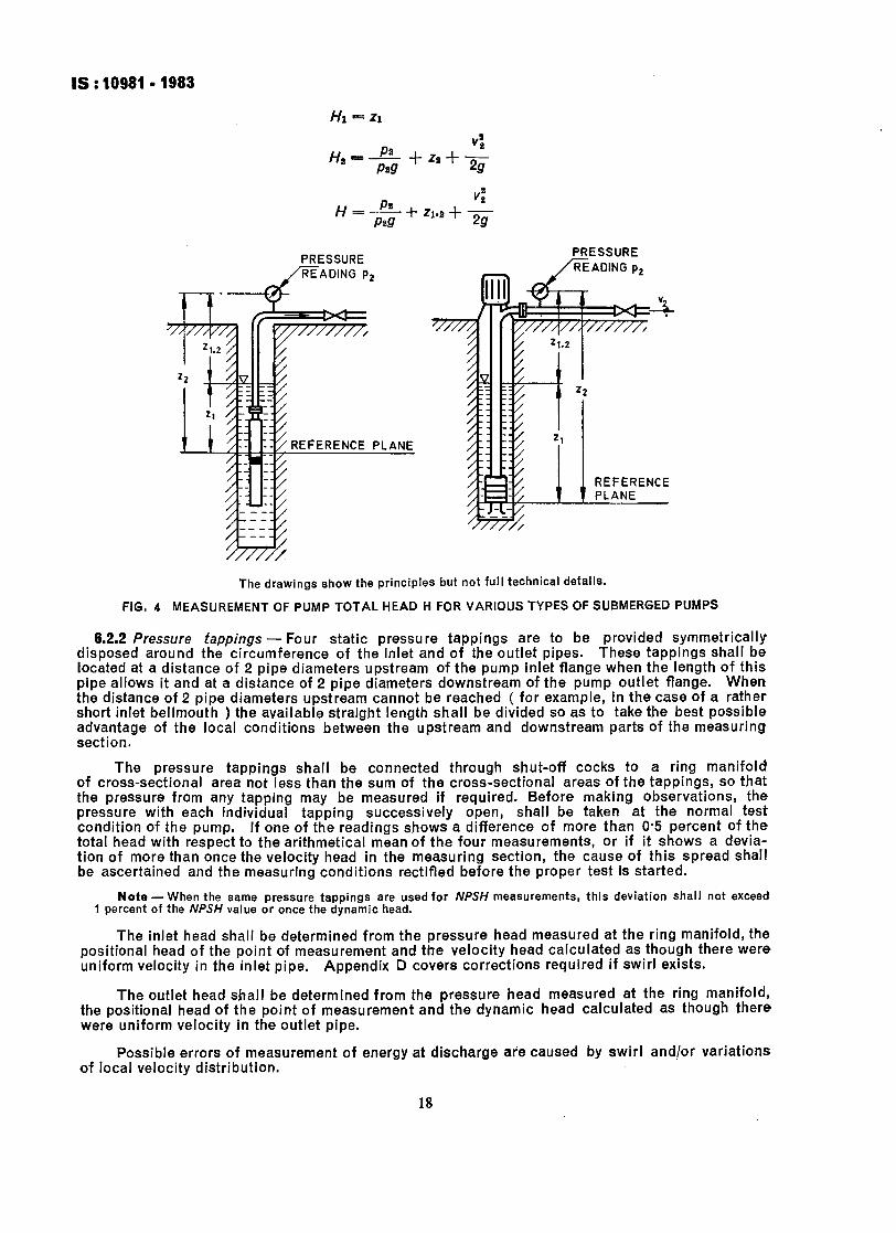
Hl = 21
I
Hs = + +I.+;
H = $- + zl.g + ;
PRESSURE /i7i?ADlN~ p2
PRESSURE -
L _/READING pz
i _I ..I_
REFERENCE rLANC
The drawings show the principles but not full technical details.
FIG. 4 MEASUREMENT OF PUMP TOTAL HEAD H FOR VARIOUS TYPES OF SUBMERGED PUMPS
6.2.2 Pressure fappings - Four static pressure tappings are to be provided symmetrically disposed around the circumference of the inlet and of the outlet pipes. These tappings shall be located at a distance of 2 pipe diameters upstream of the pump inlet flange when the length of this pipe allows it and at a distance of 2 pipe diameters downstream of the pump outlet flange. When the distance of 2 pipe diameters upstream cannot be reached ( for example, in the case of a rather short inlet bellmouth ) the available straight length shall be divided so as to take the best possible advantage of the local conditions between the upstream and downstream parts of the measuring section.
The pressure tappings shall be connected through shut-off cocks to a ring manifold Of cross-sectional area not less than the sum of the cross-sectional areas of the tappings, so that the pressure from any tapping may be measured if required. Before making observations, the pressure with each individual tapping successively open, shall be taken at the normal test condition of the pump. If one of the readings shows a difference of more than 0.5 percent of the total head with respect to the arithmetical mean of the four measurements, or if it shows a devia- tion of more than once the velocity head in the measuring section, the cause of this spread shall be ascertained and the measuring conditions rectified before the proper test is started.
Note -When the same pressure tappings are used for NPSH measurements, this deviation shall not exceed 1 percent of the NPSH value or once the dynamic head.
The inlet head shall be determined from the pressure head measured at the ring manifold, the positional head of the point of measurement and the velocity head calculated as though there were uniform velocity in the inlet pipe. Appendix D covers corrections required if swirl exists.
The outlet head shall be determined from the pressure head measured at the ring manifold, the positional head of the point of measurement and the dynamic head calculated as though there were uniform velocity in the outlet pipe.
Possible errors of measurement of energy at discharge aie caused by swirl and/or variations of local velocity distribution.
18

IS :10981-1983
Figures 2 to 6 show the application of U-tube and Bourdon type manometers to measure the pressure head plus positional head. Where single-leg manometers, Bourdon or pressure transducers are used, an allowance for the difference in altitude between the manometer reference plane and the mean height of the pressure tappings shall be added to the pressure head as read.
Static pressure tappings shall comply with the requirements shown in Fig. 5 and shall be free from burrs and irregularities and flush with, and normal to, the inner wall of the pipe.
I > Pd where d = 2 to 6 mm or -! ,6 pipe diameter whichever value is less.
FIG. 5 REQUIREMENTS FOR STATIC HEAD TAPPING
This equation is valid for pl= pI, which may be assumed for Class C tests.
FIG. 6 DIRECT MEASUREMENT OF PUMP TOTAL HEAD
The diameter of the pressure tappings shall be between 2 and 6 mm or equal to one-tenth of the pipe diameter, whichever is the less. The length of a pressure tapping hole shall not be less than two and a half times its diameter.
The bore of the pipe containing the tappings shall be clean, smooth and resistant to chemical reaction with the liquid being pumped. Any coating such as paint applied to the bore shall remain intact. If the pipe is welded longitudinally, the tapping hole shall be displaced as far as possible from the weld.
Pipes connecting pressure tappings to possible damping devices ( see 5.3.2.1 and 5.3.2.2 ) and to instruments shall be at least equal in bore to the bore of the pressure tappings. The system shall be free from leaks. It is recommended that transparent tubing be used so as to allow determination of the amount of water or air in the tubing.
6.2.3 Instruments for pressure measurement
6.2.3.1 Liquid column manometers - No calibration is required.
The minimum distance between two scale graduations shall be 1 mm.
19
IS : 10981- 1983
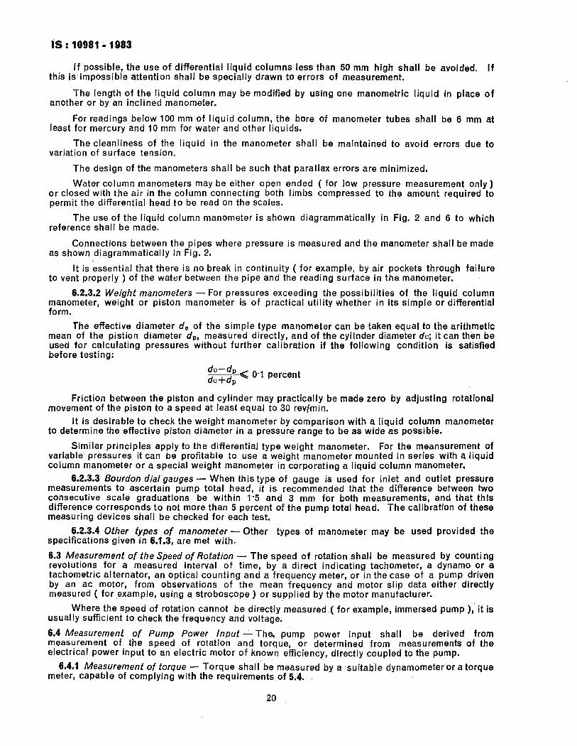
If possible, the use of differential liquid columns less than 50 mm high shall be avoided. If this is impossible attention shall be specially drawn to errors of measurement.
The length of the liquid column may be modified by using one manometric liquid in place of another or by an inclined manometer.
For readings below 100 mm of liquid column, the bore of manometer tubes shall be 6 mm at least for mercury and 10 mm for water and other liquids.
The cleanliness of the liquid in the manometer shall be maintained to avoid errors due to variation of surface tension.
The design of the manometers shall be such that parallax errors are minimized.
Water column manometers may be either open ended ( for low pressure measurement only) or closed with the air in the column connecting both limbs compressed to the amount required to permit the differential head to be read on the scales.
The use of the liquid column manometer is shown diagrammatically in Fig. 2 and 6 to which reference shall be made.
Connections between the pipes where pressure is measured and the manometer shall be made as shown diagrammatically in Fig. 2.
It is essential that there is no break in continuity ( for example, by air pockets through failure to vent properly ) of the water between the pipe and the reading surface in the. manometer.
6.2.3.2 Weight manometers - For pressures exceeding the possibilities of the liquid column manometer, weight or piston manometer is of practical utility whether in its simple or differential form.
The effective diameter de of the simple type manometer can be taken equal to the arithmetic mean of the pistion diameter dpr measured directly, and of the cylinder diameter dc; it can then be used for calculating pressures without further calibration if the following condition is satisfied before testing:
s< 0.1 percent
Friction between the piston and cylinder may practically be made zero by adjusting rotational movement of the piston to a speed at least equal to 30 rev)min.
It is desirable to check the weight manometer by comparison with a liquid column manometer to determine the effective piston diameter in a pressure range to be as wide as possible.
Similar principles apply to the differential type weight manometer. For the meansurement of variable pressures it can be profitable to use a weight manometer mounted in series with a liquid column manometer or a special weight manometer in corporating a liquid column manometer.
6.2.3.3 Bourdon dial gauges - When this type of gauge is used for inlet and outlet pressure measurements to ascertain pump total head, it is recommended that the difference between two consecutive scale graduations be within l-5 and 3 mm for both measurements, and that this difference corresponds to not more than 5 percent of the pump total head. The calibration of these measuring devices shall be checked for each test,
6.2.3.4 Other types of manometer - specifications given in 6.1.3, are met with.
Other types of manometer may be used provided the
6.3 Measurement of the Speed of Rotation - The speed of rotation shall be measured by counting revolutions for a measured interval of time, by a direct indicating tachometer, a dynamo or a tachometric alternator, an optical counting and a frequency meter, or in the case of a pump driven by an ac motor, from observations of the mean frequency and motor slip data either directly measured ( for example, using a stroboscope ) or supplied by the motor manufacturer.
Where the speed of rotation cannot be directly measured ,( for example, immersed pump ),’ it is usually sufficient to check the frequency and voltage.
6.4 Measurement of Pump Power input -The, pump power input shall be derived from measurement of the speed of rotation and torque, or determined from measurements of the electrical power input to an electric motor of known efficiency, directly coupled to the pump.
6.4.1 Measurement of torque - Torque shall be measured by a .suitab’le dynamometer or a torque meter, capable of complying with the requirements of 5.4.
20

6.4.2 Electric power measurements - Where the electrical power coupled directly to the pump is used as a means of determining following conditions shall be observed:
IS : 10981 - 1983
input to an electric motor the pump power Input, the
a) the motor shall be operated only at conditions where the efficiency is known with sufficient accuracy; and
b) motor efficiency shall be determined in accordance with the recommendations of IS : 4889-1968 ‘ Methods of determination of efficiency of rotating electrical machines’.
The electric power input to the ac driving motor shall be measured by either the two-wattmeter or the three-wattmeter method. This allows using either single-phase wattmeters or a wattmeter measuring two or three phases simultaneously or integrating watt-hour-meters.
In the case of a dc motor, either a wattmeter, or an ammeter and a voltmeter may be used.
The type and grade of accuracy of the indicating instruments for measuring electrical power shall be in accordance with IS : 1248-1968 ‘ Specification for direct cutting electrical indicating instru- ments ( first revision ) ‘.
Where the power input to an electric motor coupled to an intermediate gear, or the speed of rotation and torque measured by a dynamometer between gear and motor are used as a means for determining the pump power input, it shall be stated in the contract in what way the losses of the gear shall be determined.
6.4.3 Pumps with inaccessible ends - In the case of combined motor-pump units (for example, submersible pumps or monoset pump, or separate pump and motor with overall efficiency guarantee ), the power of the machine unit shall be measured at the motor terminals if accessible. When a submersible pump is involved, the measurement shall be effected at the incoming end of the cables; cable losses shall be taken into account and specified in the contract. The efficiency given shall be that of the combined unit proper, excluding the cable and the starter losses,
6.4.4 Deep-well pumps - In this case the power absorbed by the thrust bearing and the vertical shafting and bearings shall be taken into account.
Since deep-well pumps in general are not tested with the entire stand pipe attached, unless the acceptance test is performed at site, the thrust and vertical shaft bearing losses in regard to power and efficiency shall be estimated and stated by the manufacturer to his purchaser,
6.5 Measurement of Pumping Unit Overall EJfciency - To determine the efficiency of a pumping unit, only the power input and output are measured, with the driver working under conditions specified in the contract. In this test, the proportion of losses between driving agent and pump is not established, nor any losses associated with intermediate machinery, such as gear box or variable speed device.
7. Cavitation Testing
7.1 General - When the contract specifies a guaranteed NPSH, a test may be conducted to verify that the NPSH required by the pump is equal to or less than the guaranteed NPSH.
In no case shall the cavitation tests be used to check that the pump will be free from cavitation erosion during its service life,
7.1.1 Test fypes - There are two distinct possible types of cavitation test:
a) A check may be made simp,ly to show that the pump is sufficiently free of cavitation at the specified duty and NPSH. This type of test is described in 7.1.1.1.
b) In the other type, cavitation performance is explored more fully by measurable effects are noted.
reducing NpSH until This type of test is described in 7.1.1.2.
7.1.1.1 A test at thd.ip&ei flow rate and NPSH - This test may be made simply to show that the pump is sufficiently free of cavitation at the specified duty and NPSH.
The pump meets the requirement to be free of the effects of cavitation if another test at a ‘higher NPSH gives the same total head at the same rate of flow.
7.1.1.2 During the cavitation test NPSH carried according fo 3.2.3.12 - A safety margin previously agreed will be added to the cavitation test NPSH. The pump meets the requirement if the NPSH resulting from the addition of the cavitation test NPSH, and the agreed safety margin is equal or less than the required NPSH. From this test the behaviour of the pump at various departures from the specified NPSH may be judged. When negotiating the safety margin, account
21

IS:10981-1983
shall be taken of the type of pump, of the number of stages, of the physical properties of the liquid to be pumped and of materials of construction and the operating conditions to be expected.
7.1.2 Methods of varying the NPSH
7.1.2.1 The pump is installed in a closed pipe loop ( Fig. 7 ) in which the pressure level or, by an alteration of temperatures, the vapour pressure may be varied without changing the pump head or rate of flow until cavitation occurs in the pump.
Cavitation in outlet and inlet regulating valves may make this test more difficult and special valves may be required.
Arrangements for cooling or heating the liquid in the loop may be needed in order to maintain the required temperature, and a gas separation tank may also be required. The tank shall be of sufficient size and so designed as t6 prevent the entrainment of gas in the pump inlet flow.
TO VACUUM OR PRESSURE CONTROL
c
I II SPRAY NOZZLE FOR ~-AERATING WATER
COOLING HEATING
f-3 THE SETTLING TANK
I T _ ,8...\‘\ NOT BE NEEDED IF , /II\\ t
FLOWMETER CONTENT OF WATER CONTROLLABLE
OTTLE VALVE
I-
I I
PUMP UNDER TEST MAY BE PUT IN SYPHON IF (NPSHI < W IS NEEDED
MAY AIR
IS
Note - Cooling by means of a coil may be replaced by an injection of cool water above the liquid free surface and an extraction of heated water.
The drawing shows the principle but no full technical details.
FIG. 7 CAVITATION TESTS - VARIATION OF ( NPSH ) BY MEANS OF A CLOSED LOOP
De-aeration of water used for a cavitation test is necessary if the pump is to be used in practice with de-aerated water.
Stilling screens may be needed if ‘; > 0’25 m/s, where A is the cross-sectional area of the
tank.
7.1.2.2 The pump draws liquid from a sump in which the level of the free liquid surface may be adjusted through a pipe showing no cross-sectional restriction ( Fig. 8 ).
22

IS:10981 -1983
TO THROTTLE
FLOWMETER
i - --
- t T
- -. - --
~
--
--
F -
- -
-
- -- .
1
The drawing shows the principle but no full technical details.
FIG. 9 CAVITATION TESTS - VARIATION OF (NPSH) BY CONTROL OF LIQUID LEVEL AT INLET
7.1.2.3 The pressure of the liquid entering the pump is adjusted by means of a throttle valve installed in the inlet pipe at the lowest practical level ( Fig. 9 ).
The cavitation induced by the throttle valve can sometimes be avoided by using two or more throttle valves mounted in series or by directly discharging the throttle valve into a closed vessel, or a large diameter pipe interposed between the throttle and the pump inlet. Baffles and a means for extracting air from such a vessel may be needed, especially when the NPSH is low.
The drawing show the principles but not full technical details.
FIG. 9 CAVITATION TESTS - VARIATION OF ( NPSH ) BY MEANS OF A THROTTLE VALVE AT INLET
When the throttle valve is to be partially closed and it is situated at a distance less than 12 inlet diameters from the pump inlet flange, it is necessary to make sure that the pipe is full of liquid at the position of the inlet pressure tappings.
7.2 Determination of NPSH Required by the Pump - Tests described in 7.1.1.2 can be conducted by any of the methods indicated in Fig. 7 to 9. It is possible to vary two control parameters and thus keep flow rate constant during a test, but this is a usually more difhcult (see also Fig. IO).
7.3 Limits of Error in Deferminafion of ( NPSH) - The maximum limits of error concerning NPSH measurements shall be assumed to be 3’0 percent of the measured NPSH, or 0’15 m, whichever is greater, provided that the measurements are made with a liquid column manometer.
23

Type of Open Sumr Open Sump Closed Installation Loop
Independent Inlet throttle variable valve
Water level Reference Temperature Outlet throttle valve Inlet throttle Pressure in (vapour valve
Water level Temperature pressure the tank
pressure ) ( vapour pressure )
Constant Outlet throttle valve
Quantities the Head, flow variation of rate, NPSH, which is de- water level pendent on control
Head charact- eristic curves various flow rate and NPSH
Closed Sump or
Loop
Open Sump Open Sump Closed Loop ‘Open Sump Closed Loop
Inlet and outlet throttle valves
Inlet and outlet throttle valves
Inlet throttle valve Flow rate Flow rate Flow rate Flow rate
Head flow Head, flow after onset Head, flow rate, NPSH, water Outlet Head NPSH, NPSH, rate, NPSH rate, NPSH
1 of throttle
NPSH, head, level outlet throttle head, outlet outlet throttle
cavitation valve ( for valve ( for throttle valve (for constant constant flow valve constant flow flow rate ), rate, when rate, when head, NPSH head begins
to drop ) head begins to drop )
H
I p3* !$H,/lOO
I q”, = CONS7
HI
qv, :CONST > qvi
HI
Hk I III q,,.CONST > qvl
I 0 1---c
I ; 6 1 I 1 (NPSHI
1 I k MEASURED
k - -----_ _ ----
NPSH Charact-
4”)
FIG, IO r,qETHQDS OF DETERMINING REQUIRED (NPSH) for a H/i-/=(3+x 1%
IS:10981-1983
The case of tests with liquids at high temperature or near their critical points shall be studied with special care in the contract.
7.4 Measurement of Pump Head, Out/et Flow Rate, Speed of Rotation, Power Input ( if Necessary 1 and Vapour Pressure - The requirements of 6 regarding the measurement of head, outlet rate of flow, speed of rotation and power input shall also apply during cavitation tests. If the test conditions are so unsteady as to require repeated readings, variations of NPSH are permitted up to a maximum of l-5 times the values given for head in Table 5, or O-15 m, whichever is greater.
Particular care is needed to ensure that in the flow measurement cavitation dose not affect the accuracy of the flowmeter. It is also necessary to take care to avoid the ingress of air through joints and glands.
The vapour pressure of the test liquid entering the pump shall be determined with sufficient accuracy to comply with 7.3. When the vapour pressure is derived from standard data and the measurement of the temperature of the liquid entering the pump, the necessary accuracy of temperature measurement may have to be demonstrated.
The active element of a temperature-measuring probe shall be not less than one-eighth of the inlet pipe diameter from the wall of the inlet pipe. If the immersion of the temperature measuring element in the inlet flow is less than that required by the instrument manufacturer, then a calibration at that immersion depth may be required.
Care shall be taken to ensure that temperature measuring probes inserted into the pump inlet pipe do not influence the measurements of inlet pressure.
8. Tests on Pumps for Liquids other than Clean Cold Water -The performance of a pump may vary substantially with the nature of, the liquid being pumped. Although it is not possible to give general rules whereby performance with clean cold water can be used to predict performance on dnother liquid, it is often desirable for the parts to agree on empirical rules to suit the particular circumstances and test the pump with clean cold water.
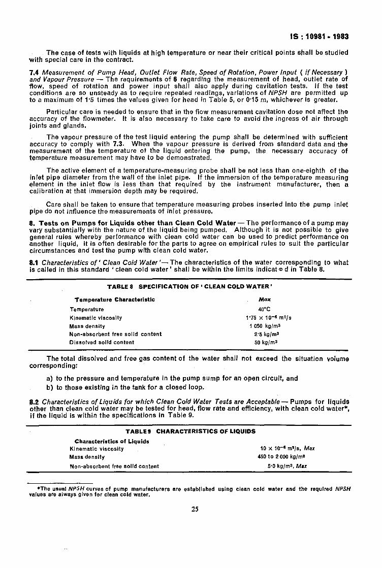
8.1 Characteristics of ‘ Clean Cold Water ‘- The characteristics of the water corresponding to what is called in this standard ‘ clean cold water ’ shall be within the limits indicat (D d in Table 8.
TABLE 8 SPECIFICATION OF ‘ CLEAN COLD WATER’
Temperature Characteristic Max
Temperature 40°C
Kinematic viscosity 1.75 x 10-s rn2l.s
Mass density 1 050 kg/m3
Non-absorbent free solid content 2’5 kg/ma
Dissolved solid content 50 kglms
The total dissolved and free gas content of the water shall not exceed the situation volume corresponding:
a) to the pressure and temperature in the pump sump for an open circuit, and
b) to those existing in the tank for a closed loop.
8.2 Characteristics of Liquids for which Clean Cold Water Tests are Acceptable - Pumps for liquids other than clean cold water may be tested for head, flow rate and efficiency, with clean cold water*, if the liquid is within the specifications in Table 9.
TABLE 8 CHARACTERISTICS OF LIQUIDS
Characteristics of Liquids
Kinematic viscosity 10 x 10-s m%/s, Max
Mass density 450 to 2 000 kg/ms
Non-absorbent free solid content 5.0 kg/ms, Max
*The usual NPSH curves of pump manufacturers are established using clean cold water and the required NPSH values are always given for clean cold water.
25

IS:10981 -1983
The total dissolved and free gas content of the liquid shall not exceed the saturation volume corresponding:
a) to the pressure and temperature in the pump sump for an open circuit, and b) to those existing in the tank for a closed loop.
Tests on pumps for liquids other than those specified above shall be subject to special agreement.
In the absence of a special agreement cavitation tests shall be carried out with clean cold water. Attention is drawn to the fact that the results may be affected by this procedure when the liquid to be pumped is not clean cold water.
9. Analysis of Tests
9.1 Test Data Required for the Analysis -The quantities required to verify the characteristics guaranteed by the manufacturer are given in 4.1.
Methods for measuring these quantities are given in 6.
9.2 Translation of the Test Results to the Guarantee Basis-Such translation serves to determine whether the guarantee would have been fulfilled if the tests had been concluded under the same conditions as those on which the guarantee is based.
9.2.1 Translation of the test results into data based on the specified speed of rotation of frequency - All test data obtained at the speed of rotation, in deviation from the specified speed of rotation nap do not exceed the permissible variations stated in 5.3.3, the measured data on the discharged flow rate qv the total head H, the power input P, the net positive suction head NPSH and the efficiency q can be translated as follows:
QTO - qv ( > nsp n
no = n
If the deviations in speed of rotation from the specified speed of rotation nsp exceed the per- missible variations stated in 5.3.3 it will be necessary to stipulate the formula for translating the test results to the basis of the specified speed of rotation.
In the case of combined motor-pump units or where the guarantees are with respect to an agreed frequency and voltage instead of an agreed frequency and voltage instead of an agreed speed ( see 4.1 ), the flow rate, pump total head, power input, and efficiency data are subject to the above-mentioned translation laws, provided that n sp is replaced by the frequency fsp and n by the frequency f. Such translation, however, shall be restricted to the cases where the frequency during the acceptance test varies by no more than 1 percent from the frequency prescribed for the charac- teristics under guarantee. If the voltage used in the acceptance test is no more than 5 percent above or below the voltage on which the guaranteed characteristics are based, the other operational data require no change.
If the above-mentioned tolerances, that is 1 percent for frequency and 5 percent for voltage, are exceeded, it will be necessary for the purchaser and the manufacturer to arrive at an agreement.
9.2.2 Tests made with NPSH different from that guaranteed - Pump performance at a high NPSH cannot be accepted ( after correction for speed of rotation within the permitted limits of 5.3.3.2 ) to, indicate performance at a lower NPSH.
Pump performance at a low NPSH can be accepted after correction for speed of rotation within the permitted limits of 5.3.3.2, to indicate performance at a higher NPSH provided that the absence of cavitation has been checked in accordance with 7.1.1.1.
9.3 Measuring Inaccuracies - Every measurement is inevitably subject to inaccuracies, even if the measuring procedure and the instruments used, as well as the analysis directives, fully comply with prevailing acceptance rules. When comparing the test results with the guaranteed characteristics, these inaccuracies shall be given adequate consideration. The fact should be stressed that the term ’ measuring inaccuracies ’ merely covers the errors that are unavoidable with all measure-- ments; they refer in no way to the pump and the guaranteed characteristics. The maximum permL- ssible limits of overall error for the quantities used in Class B measurements are defined in Table 7..
26

IS : 199819 1983
9.4 Verification of Guarantee
9.4.1 Curves q, H and qg - The guarantee points qvHa and qvQylo are plotted on a graph and a continuous curve is then drawn through the measured points qvH and another through the points ovq of which qv is measured and q is calculated ( Fig. 11 ).
If the test is made at a value of speed that is different from that specified as relevant to the particular guaranteed values, the test values shall be corrected to the specified speed of rotation in accordance with 9.2.1. Similarly, if the test is made at a value of frequency different from that rele- vant to the particular guaranteed values, the tests shall be corrected to the specified frequency.
Tolerances f Xq, and XH shall be applied to the guaranteed duty point qvoHa. These toleran- ces include the maximum permissible limits of overall error e pV and eH ( see Table 7 ) and the constructional tolerances.
In the absence of a specific agreement as to the values to be used, the following values may be taken:
xg, = & 0.04 xlr = zt 0’02
If the guaranteed point ties at a vertical distance f AH and a horizontal distance f Aqv from the test curve ( see Fig. 11 ), the following shall be evaluated:
(&J+(!+$+v)1 .
If the amount is greater than or equal to 1 the guarantee condition will be deemed to have been met; but if the total amount is less than 1, the guarantee condition has not been achieved.
Note - This quantity expresses the fact that there is at least one point of the test curve Within an ellipse Of Which the eentre is the guaranteed duty point and the semi-axes the limiting errors:
’ qvaxqv’ and ‘Hgx H’
This, however, does not allow to check that a given flow rate qv is obtained for the guaranteed head Ho nor that azgiven head H is obtained for the guaranteed flow rate qva.
It should actually be noted that checking this relationship does not necessarily imply that:
a) for the guaranteed flow rate qvG, a head H is obtained such that:
H~-&JXH~H<H~+&IXH
b) for the guaranteed head Ha a flow rate qv is obtained such that:
Qva - Qva x cv <Qv< 9vo + qra x qv
Ii GUARANTEED DUTY
Po’NT q,,ll,
FIG. 11 CURVE qv H FOR VERIFICATION OF GUARANTEE
27
IS:10981 -1983
9.4.2 Efficiency - The guaranteed efficiency shall be checked for the duty point as defined by the point of intersection of curve +/-/ with a straight line passing through the guaranteed duty point gVoHo and the zero of gJ-/ axes. The efficiency at this point shall be read on the qvq curve versus the corresponding abscissa.
The efficiency at the point of intersection shall be of at least 0,972 of that specified.
For combined motor-pump units this value is 0.975.
These values take into account the measuring errors ( see Table 7 ).
9.4.3 Pump power input - The pump power input within the range Q”O f X,, Ha f XH defined in 9.4.1, shall not exceed that agreed between the manufacturer and purchaser at the time of contract. This value applies to the conditions of use of the pump as specified in the contract.
Such an arrangement may have to take into account different transmission losses and different gland and seal torques between works test and site operation.
9.5 Test Report -After actual scrutiny, the test results shall be summarized in a report, that is
signed by the chief of tests alone; or, together, by him and representatives of the manufacturer and of the purchaser.
All parties to the contract shall receive a copy of the report as an essential condition for the completion of the contract.
The test report should contain the following information:
a) Place and date of acceptance test;
b) Manufacturer’s name, type of pump, serial number, and possibly year of construction;
c) Guaranteed characteristics and operational conditions during the acceptance test;
d) Specification of the pump’s drive;
e) Description of the test procedure and the measuring apparatus used including calibration data;
f ) Observed readings:
g) Evaluation and analysis of test results; and
h) Conclusions:
1) comparison of the test results with the guarantees;
2) determination whether the guarantees covering certain specific areas were completely or only partly fulfilled or not fulfilled at all;
3) recommendation whether the pump can be accepted or should be rejected and under what conditions; and
Note- If the guarantees are not fully satisfied the final decision whether the pump can be accepted or not is up to the purchaser.
4) statements arising out of action taken in connection with any special agreements that were made.
The pump test sheet ‘SI’ conversion factors and check list pro forma are given in Appendices E, F and G respectively.
APPENDIX A
( CIause 5.2 )
PUMPING INSTALLATION UNDER NON-STANDARD CONDITIONS
A-l. Where it is impracticable to test a pump in accordance with the standard test conditions specified in 5.2, or where alternatively it is required to ascertain the performance of a pump, not under standard conditions, but under the conditions in which it will work when installed, or where it is desired to test the performance of a pumping installation including items other than the pump itself, then the following decisions shall be made and recorded with the test results:
a) The precise range of the items to be included in the installation to be tested.
Note -Where auxiliary plant is involved, whether the consumption of each individual item is or is not to be debited to the installation.
28

IS : 10981-1983
b) The exact positions in the proposed layout at which inlet head and outlet head ( or their difference ) are to be measured.
c) The point in the circuit, the flow past which is to be credited to the installation.
d) The nature of the supply of energy ( for example, mechanical, electric, fuel, steam, hydraulic or pneumatic ).
e) The position, or positions, at which the supply of energy is to be measured.
f) The method as laid down in the foregoing specification which is to be used for hydraulic measurements; the method as laid down in other relevant Indian Standards to be used for measurement of power, fuel, etc, both quantitative and, where necessary, qualitative; the method of measurement to be used where no Indian Standard exists.
g) The extent to which the conditions pertaining during the tests may vary from the specified conditions.
h) Where lubricating oil or other consumable stores are to be taken into consideration, the methods of measurement to be used for these.
j) The proposed date(s), usually referred to the date of installation, of the tests, their dura- tion and the frequency with which readings are to be taken.
APPENDIX B
( Clause 5.3.1 )
COSTS AND REPETITION OF TESTS
8-O. Matters of a purely commercial nature, such as the cost of the tests are not included in the scope of this Indian Standard and shall be made the subject of special agreements between the parties concerned.
8-l. Costs of Acceptance Tests and Special Tests - It is recommended that the costs of acceptance tests and special tests be clearly stated in the contract.
8-2. Repetition of Tests- In case of doubt as to the correctness or adequate accuracy of the measurement data obtained, both the manufacturer and the purchaser are entitled to demand that the test be repeated. Should the new measurement fail to justify the doubts expressed, the party demanding the renewed test shall assume the cost of repetition.
APPENDIX C
( CIauses 6.2.1.2 and 6.2.1.6.2)
FRICTION LOSSES
C-l. The formula given in 6.2.1.2 for calculating head loss due to friction involves a lengthy calculation, which would lead only in many cases to the conclusion that a correction need not be applied.
C-2. The chart in Fig, 12 may be used as a preliminary check as to whether a calculation needs to be made. It applies to straight steel pipes of constant circular cross-section, handling cold water. Outlet and inlet pipes are assumed of equal diameter, and measuring points 2 diameters upstream and downstream of the inlet and outlet flanges respectively.
C-3. If the pipes are of different diameters, the diameter of the smaller pipe should be used. Then if ‘ no correction ’ is indicated, the calculation need not be made.
C-3.1 If ‘ correction ’ is indicated, Fig. 13, which applies only to steel pipes handling cold water, may be used to determine the value of A.
29

IS:10981 -1983
180
160
80
60
40
40
0 0 1 2 3 4 5 6 7 8 9 10
VELOCITY ( m I s I
FIG. 12 CHART SHOWING VELOCITIES ABOVE WHICH LOSS CORRECTIONS ARE REQUIRED
SO
100
150
200
250 300
350 400
500
600
750
30


IS : 10981 - 1983
C-4. In cases where pipes are of other material, or the liquid is not cold water the graph by Moody aiven in Fig. 14 may be used, or the formula for h given in 6.2.1.2 may, if preferred, be solved. For the pipe roughness k one m&y take the values given in Table 10.
L AMINAR FLOW CRITICAL ZONE
A
0.06
0.05
0.01
0.03
0.025
0.02
000
lo3 2 34566104 2 3 4566lt-f’ 2 346661@ 2 346661
REYNOLDS NUMBER Re=$
FIG. 14 VALUES OF FRICTION FACTOR A MOODY CHART
TABLE IO ABSOLUTE ROUGHNESS k FOR PIPES
Commercial Pipe ( New ) Material Absolute Roughness k of the Surface
Glass, drawn brass, copper or lead
Steel Asphalted cast iron
Galvanized iron
Cast iron Concrete
Riveted steel
Smooth
0.05 mm
0.12 mm
0.15 mm 0’25 mm
0.3 to 3.0 mm
1.0 to 10.0 mm
32

IS:10981 -1983
APPENDIX D
( C/ause 6.2.2 )
EFFECT OF PRE-SWIRL INDUCED BY THE PUMP
D-l. Errors in the measurement of pump inlet head can occur at part capacity due to pre-swirl. These errors can be detected and corrected on the following basis.
D-2. The differential head is measured between the specified inlet measuring section and another position further upstream where the pre-swirl induced by the pump is known to be absent ( for example the sump ), This differential head should follow a quadratic law with flow; any departure from this law will show the amount by which an inlet head measurement shall be corrected for the effect of pre-swirl induced by the pump ( see Fig. 15 and 16 ).
GAUGE USED FO DETERMINATION
FIG. 15 EXAMPLE OF INSTALLATION WITH PRE-SWIRL
ONSET OF PRE-SWIRL
FIG. 16 CORRECTION OF MEASURED INLET HEAD
APPENDIX E
( Clause 9.5 )
PUMP TEST SHEET
E-l. The pump test sheet is given for guidance for presenting pump their interpretation. It does not purport to include all the information modifications may be necessary depending on the type of pump, its calculation.
33
test results and to assist in required from a pump test and application, and the mode of

IS:10981 -1983
‘UMP TEST SHEET ( Class B ) 1 Sheet No. Nature of test
:ustomer
Maker’s Order Number
iuaranteed Volume rate of flow ( qvo ) Speed of rotation (f&p) Power input
Net positive suction head ( NPSH )
kinematic viscosity (V)
Test cetirficate
Speed of rotation
‘est conditions Room temperature Head correction to Barometric pressure
lesults of measurement
Notes Chief of tests Representatives
of the customer of the manufacturer
34

APPENDIX F ( Chose 9.5 )
IS : 10981 - 1983
CONVERSION TO SI UNITS
F-l. This Appendix gives factors for conversion to St for covering units of some of the quantities expressed in multiples or sub-multiples of SI units and in units other than SI units. The conversion factor is the number by which the value expressed in various units should be multiplied to find the corresponding va1u.e in SI units.
TABLE 11 CONVERSION FACTORS
Quantity Symbol of SI Unit Various Units Conversion Factors
Name Symbol
Volume rate of flow’ ms/s iitre per second I/s IO-3
cubic metre per hour ma/h 1 I3 600
litre per hour I/h l/3 600 000
litre per minute I/min l/60 000
imperial gallon per minute gal ( UK )/min 0,000 075 77
cubic foot per second ff3/S 0,028 316 8
gallon ( US) per minute gal ( US)/min 0,000 063 09
barrel ( US ) per hour ( petroleum) barrel ( US)/h 0,000 044 16
Mass rate of flow kg/s ton per second t/s 103
ton per hour th l/3.6
kilogram per hour kg/h 1 I3 600
pound per second lb/s 0,453 592 37
Pressure Pa kilopond per square centimetre kp/cms -l kilogram-force per square centi- kgf/cms
metre J> 98 066,5
bar bar 7
hectopieze hpz t 105
J torr torr 1 conventional millimetre of mercury mmHg > 133,322
conventional millimetre of water mmH,O J
9,806 65
poundal per square foot pdl/fts 1,488 16
standard atmosphere atm 101 325
pound-force per square inch Ibf/ins (psi ) 6 894,76
Density. kg/m3 kilogram per cubic decimetre kgjdms 7
gram per cubic centimetre g/cm3 ! ‘OS pound per cubic foot Ib/fts 16,018 5
Power W kilowatt kW 103 kilopond metre per second kp’m/s 9,806 65 I. T. kilo calorie per hour kcalIT/h 1,163 cheval vapour 1) ch 735,5 horsepower’) hp 745,7 British thermal unit per hour Btu/h 0,293 071
kilogram-force metre per second kgt.m/s 9,806 65
Viscosity Pa.s ( kg/m.s ) decapoise daP 1 (dynamic viscosity)
poise P 7
dyne second per square centimetre dyn.s/cma 1 10-l
gram per second centimetre glsmcm J
kilopond second per square metre kp*s/m” 9,806 65
centipoise
poundal second per square foot pdl.s/ftz
Kinematic viscosity
Fj ;z/L(;; per second
St = ems/s
f;;L
1) No international symbol exists for this unit; the symbol shown is the most common.
35

IS:10981 -1983
APPENDIX G ( Clause 9.5 )
CHECK LIST
G-l. The following is a check list of items where agreement is recommended between manufactu- rer and purchaser before the test. It should be noted that it will not always be necessary to agree upon all these items during the elaboration of the contract:
a) extent of guarantee: 1) pump without motor ( see 4.1 ); 2) combined motor-pump unit ( see 4.1 ); 3) guarantee values ( for example flow rate, total head, power input, efficiency, NPSH,
etc. ) ( see 4.1, 4.2 and 9.4.3 );
b) method of verification of guaranteed NPSH ( see 7.1.1 );
c) rotational speed deviations outside permissible tolerance ( see 5.3.3.2 ); d) voltage and frequency deviations outside permissible tolerance (see 9.2.1 ); e) method of prediction of pump performance from a test using clean cold water ( see 8 ); f) liquid to be used for acceptance test; g) inlet and transmission losses in vertical well pumps ( see 6.2.1.6 and 6.4.4 ); h) cable losses ( see 6.4.3 ); j ) gear losses ( see 6.4.2 ); k) arrangement for proving priming ability of self-priming pumps ( see 5.2.6 ); m) time of tests ( see 5.1.2 ); n) test equipment ( see 5.1.5 ); p) test arrangement ( see 5.2.1 and 5.2.2 );
q) use of recognized methods of measurement other than those described in this standard;
r) chief of test when test is not carried out at manufacturer’s works ( see 5.1.3 );
s) test costs ( see Appendix B );
t) number of pumps to be tested in a batch of identical pumps; and
u) any other aspect of pump behaviour to be checked during the test.
EXPLANATORY NOTE
This standard is the second of a set of three dealing with acceptance tests of centrifugal, mixed flow and axial pumps; they correspond to three classes of Tests A, B and C; Class A is the most accurate and Class C is the least accurate; the use of Classes A and B pumps is restricted to special cases when there is need to have the pump performance more precisely defined. It should be borne in mind that tests for Class A and B pumps require moreaccurate apparatus and methods, which increase the cost of such tests.
The standard arrangements and procedures described are those to be employed for testing a pump individually, without reference to its final installation conditions or the usual conditions in which a pump is tested at the manufacturer’s works.
Pump performance may be affected by conditions of the final site installation, and procedures are described for carrying out ‘ Standard Tests ’ on certain types of installations of which an overall performance is required.
The conditions in which pumps are finally installed, however, often do not permit reliable tests measurements, and recommendations are made concerning the procedure to be adopted here the layout precludes tests in conformity with the standards, or where the tests cover the pump and the plant ancillary to the pump itself.
While preparing this standard, considerable assistance has been derived from International Standard IS0 3555-1977(E) ‘Centrifugal, mixed flow and axial pumps - Code for acceptance - Class B’ issued by the International Organization for Standardization.
36
Printed at New lndla Printlno Press, Khuria, lndla