is 101-6-5 (1997): method of sampling and test for paints
TRANSCRIPT

Disclosure to Promote the Right To Information
Whereas the Parliament of India has set out to provide a practical regime of right to information for citizens to secure access to information under the control of public authorities, in order to promote transparency and accountability in the working of every public authority, and whereas the attached publication of the Bureau of Indian Standards is of particular interest to the public, particularly disadvantaged communities and those engaged in the pursuit of education and knowledge, the attached public safety standard is made available to promote the timely dissemination of this information in an accurate manner to the public.
इंटरनेट मानक
“!ान $ एक न' भारत का +नम-ण”Satyanarayan Gangaram Pitroda
“Invent a New India Using Knowledge”
“प0रा1 को छोड न' 5 तरफ”Jawaharlal Nehru
“Step Out From the Old to the New”
“जान1 का अ+धकार, जी1 का अ+धकार”Mazdoor Kisan Shakti Sangathan
“The Right to Information, The Right to Live”
“!ान एक ऐसा खजाना > जो कभी च0राया नहB जा सकता है”Bhartṛhari—Nītiśatakam
“Knowledge is such a treasure which cannot be stolen”
“Invent a New India Using Knowledge”
है”ह”ह
IS 101-6-5 (1997): Method of sampling and test for paints,varnishes and related products, Part 6: Durability test onPaint films, Section 5: Accelerated weathering test [CHD20: Paints, Varnishes and Related Products]

IS 101 (Part G/Set 6) : 1997
Indian Standard
METHODSOFSAMPLINGANDTESTFOR PAINTSJARNISHESANDRELATED
PRODUCTS PART 6 DURABILIN TESTS ON PAINT FILMS
Sectlon 5 Accelerated Weathering Tests
ICS 87.040
OBIS 1997 : . . :
BUREAU OF INDIAN S’i’ANDARDS MANAK BHAVAN, 9 BAHADUR SHAH ZAF’AR MARG
NEW DELHI 110002
December 1997 PriceGroup 8
xxxxxx2007
Paints (Other than Industrial Paints) and Allied Products Sectional Committee, CHD 020
FOREWORD
This Indian Standard (Part 6/SecS) was adopted by the Bureau of Indian Standards, after the draft finalized by the Paints (Other than Industrial Paints) and Allied Products Sectional Committee had been approved by the Chemical Division Council.
The durability of the material is determined by ascertaining actual behaviour of suitably prepared test panels by an accelerated weathering test wherein a prepared panel is subjected to controlled exposure of heat, light and water in the artificial weathering apparatus and evaluating the results of the exposure by a suitable method of rating for various characteristics of the film of the material.
Since the natural environment varies with respect to time, geography and topography. It may be expected that the effects of natural exposure will vary accordingly. All materials are not affected equally by the same environment. Results obtained by using different methods should not be represented as equivalent to those of any natural weathering tests until the degree of quantitative coordination has been established for material under reference.
These days, carbon arc method is not used much by industries and institutions as availability of this equipment and spares has become difficult and as newer and more comprehensive methods are now available. Carbon arc method would be discontinued in course of time and the position will be reviewed after two years.
This standard is one of a series dealing with sampling and testing of paints, varnishes and related products. In the preparation of this standard, considerable assistance has been derived from ASTM 23,26 and 53.
The composition of technical committee responsible for the formulation of this standard is given in Annex A.
In reporting the result of a test or analysis made in accordance with this standard, if the final value, observed or calculated, is to be rounded off, it shall be done in accordance with IS 2 : 1960 ‘Rules for rounding off numerical values (revised)‘.

IS 101 ( Part 6/&c 5 ) : 1997
Indian Standard
METHODS OF SAMPLING AND TEST FOR PAINTS, VARNISHES AND RELATED
PRODUCTS PART 6 DURABILITY TESTS ON PAINT FILMS
Section 5 Accelerated Weathering Tests
1 SCOPE
This standard (Part 6/Set 5) prescribes the following three methods for accelerated weathering tests :
a) Carbon arc, b) Xenon arc, and c) UV condensation type.
2 REFERENCES
The Indian Standards listed below contain provisions which through reference in this text, constitute provision of this standard. At the time of publication, the editions indicated were valid. All standards are subject to revision and parties to agreements based on this standard are encouraged to investigate by dated or undated the possibility of applying the most recent editions of the standards :
IS No.
101
(Part l/Set 3) : 1986
(Part 6/&c 1) : 1988
1017 : 1966
Title
Methods of sampling and test for paints, varnishes and related products:
Part 1 Test on liquid paints (general and physical), Section 3 Preparation of panels (third revisibn)
Part 6 Durability tests on paint films, Section 1 Resistance to humiditv under conditions of condensation (third revision)
Chamois leather (secondrevLGon)
3 PREPARATION OF TEST PANELS
3.1 The panel shall be mild steel plate, 0.8 mm thick and free from surface defects. Panels for the test shall be 150 mm x 75 mm. The panels shall be prepared and cleaned as prescrii in 2 of IS 101 (Part l/&c 3) and in 2.2 of IS 101 (Part 6/ Set 1).
The back and edges of the panels shall be protected with two coats of a suitable paint.
3.1.1 Unless otherwise specified, prior to exposing coated panels in the apparatus, condition them in ambient condition for one of the following periods in accordance with the type of coating:
a) Baked coatings 24h b) Radiation cured coatings 24h c) All other coatings 7 days
4 CARBON ARC METHOD
4.1 APparatus
The apparatus employed shall use one carbon arc lamps as the source of radiation and shall be one of the following types. The term cycle is defined as the total time intervals of light and water spray.
4.1.1 7jpe EH
Single open-flame sunshine carbon arc lamp apparatus, 959 mm diameter specimen rack, automatic control of temperature and cycle with 1 rpm of the specimen rack with automatic control of humidity.
4.1.2 Tvpe HH
Single enclosed carbon arc lamp apparatus, 508 mm diametre specimen rack, automatic control of temperature and cycle with 1 rpm of the specimen rack with automatic control of humidity.
4.13 The apparatus shall consist of a suitable frame within which a test chamber and necessary compartments, for housing control and regulating equipment, are located.
4.1.4 Provision shall be made for mounting or sup- porting the test specimens in a circular rack or drum that is rotated around the arc, providing uniform distribution of the radiation on all specimen.
4.1.5 Adequateventilation shall be provided in the test chamber to prevent contamination of the specimens from products of combustion of the arc.
4.1.6 The apparatus shall include equipment necessary for measuring and controlling the follow- ing:
a) b) c) d) e) f) g)
Arc current Arc voltage Black-panel temperature Water spray pressure Operating schedule or cycle Exposure time Relative humidity
4.1.7 Types EH and I-B-I apparatus are equipped
IS 101 ( Part 6/!&x 5 ) : 1997
with thermostatically actuated vapourizing units adding moisture to the air as it passes through the conditioning chamber prior to its entry to the test chamber. Relative humidity of the air in the test chamber is calculated from readings of wet and dry-bulb thermometers, either indicating or recording whose sensing part is located in the air stream ,at the point of exit from the test chamber.
4.1.8 The black-panel thermometer unit shall consist of 1.5 mm stainless steel panel of size 70 mm x 149 mm, mechanically fastened to a stainless steel bimetallic dial type thermometer. This thermometer shall have a stem of 3.99 mm diameter and a dial of 44.4 mm diameter. The sensing portion, extending 38 mm from the end of the stem, shall be located in the centre of the panel, 64 mm from the top and 48 mm from the bottom of the panel. ?lte face of the panel with the thermometer stem attached, shall be finished with two coats of a baked-on black enamel, having resistance to light and water. Control of the black-panel temperature shall be accomplished by thermostatic control of continuous flow of air over the specimen; control of temperature through on-off flow of air in the room, may be permissible.
4.1.8.1 A thermocouple or resistance bulb ther- mometer mounted at the centre face of the black- panel, which provides temperature values equivalent to the dial thermometer, may be used.
4.1.8.2 Detailed requirements and operating con- ditions of the apparatus are given in Table 1 and Fig. 1 and Fig. 2.
Table 1 Detailed Requirements and Operating Conditions of Light and Water Exposure Apparatus
SI NO.
Charaekrktks
i) Line voltage, V
ii) Arc voltage, v
iii) Arc cumnt, A
iv) Carbon ckctrode~ (upper)
v) carbone-oawa) vi) Globe
vii) Flat pan&
viii) Diameter of rpccimen drumorra&mm
xi) Speed of rotation of drum
x) Automatic arc feed
xi) splay (see figure for arrangement, locdtiou and capacity)
Reqairemnt A
r \
mm -mew #w)to250 2osIo250
481052 l#) to 145
5gto62 lSto17
CoppcraW!dumBhine’) Ncutml aed orrolidz,
do do
Optical, heat resistant ghua3)(with cut otTrt2750A”andwithminaearcin ~to9lpauntat37OOA~.
Optical, heat resistant glau with light tranUni%3iiptQpl%W8itOiitoFig.l.pyra btand9 (4.5 mm thick) hsr the following tranamissiicharact&ticq 1 pa-cent at 276 MI, 5puumtat282nmand50pWccntat303nm. C4Jtrx branb, (4 mm thikq baa the following characteristic; 1 pcrceut at 247 nm, 5 pcraut 8t 259 nm and 50 percent at 286 mu.
959 508
lrpm Motoropaatcd
Fig. 1
lrpm Solenoid operated
fig.2
‘ho. 22 copper aWed mMhinc carbon ckumda radNo.U.5O~CXWd8WhittCcarboll ckuz&sorquivak!nt.
z)No. 70 solid carbon dcctrodanndNo.#)amddedroder orapdvaknt.
‘INo. 9200 Px or equivaknt.
3740 Pyrex filter pailsal or cqldvaknt.
jJ7058 Col-ez filter pas8cs or c@vaknt.
2

IS 1.01 ( Part 6/Set 5 ) : 1997
DIA 959 FACE OF SPECXMEN TO
FACE OF SPECIMEN
J
117.5 NOZZLE TIP TO FACE OF SPECIMEN
I DIRECTION OF ROTATION
1 RPM
4 NOZZLES EMPLOYED 1 TYPE EMPLOYED F-85 LITBES 08 WATER PER MINUTE FOR SPECIBEN SPRAY UNIT EQUIPPED WITH 4 NOZZLES OPERATED AT A NOZZLE PRESSURE OF 124 TO 172 &Pa; 0.26 TO 0.36 LITRE PEE MINUTE
SPRAY _E
All dimensions in millimetrea
FIG. 1 SPECIMEN SPRAY ARRANGEMENT FOR TYPE E AND EH, SINGLE OPEN -
FLAME SUNSHINE CARBON-ARC LAMP A~PARATIJS
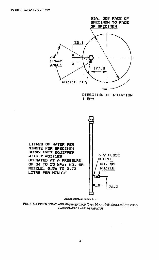
ISlOl( Part6/Sec5): 1997
DIA. 508 FACE OF SPECIMEN TO FACE OF SPECIMEN
NOZZLE TIP
DIRECTION OF ROTATION 1 RPM
LITRES OF WATER PER tlINUTE FOR SPECIMEN SPRAY UNIT EQUIPPED WITH 2 NOZZLES OPERATED AT fi PRESSURE OF 34 TO 55 kPat NO. 50 NOZZLE, 0.56 TO 0.73 LITRE PER MINUTE
3-2 CLOSE NIPPLE
All dimensions in millimetres.
FIG. 2 SPECIMENSPRAYARRANGEMENT FOR Typo H AND HH SINGLEENCLOSED CARBON-ARCLAMPAPPARATUS

4.2 Procedure
4.2.1 Prepare specimens in duplicate as prescribed in 3. Mount the teat specimen vertically both above and below the horizontal centre line of source of the radiation. To assure uniform total irradiation over the specimen surface, specimens should be repositioned vertically in a sequence which will provide each specimen equivalent exposure period in each location. When the exposure interval does not exceed 24 h, each specimen should be located equidistant from the horizontal axis of the arc.
4.2.2 Temperature measurement and control shall be based on the black-panel thermometer unit. Support the panel with the thermometer attached in the specimen-drum or rack in the same manner as the test specimen, so that it will be subjected to the same influence. Where exterior indicator is not available, read black-panel temperatures through the window in the teat chamber-door.
4.2.3 Programme the instrument to operate in a continuous light on mode. Fill specimen-rack with blanks and the black-panel thermometer. Operate in this mode while adjusting dry bulb temperature to provide desired black-panel temperature.
4.2.4 The water from the specimen spray shall strike the specimens in the form of a tie spray equally distributed on the test specimens. Unless otherwise specified the water pressure, number, and type of nozzles shall be in accordance with details as indicated in Fig. 1 or Fig. 2. The water shall have apH of 6.0 to 8.0 contain less than 20 ppm solids and leave no objectionable deposit or stain on the specimens.
4.2.5 The temperature of the water shall be 25 + 5°C and recirculation of water shall not be permitted unless the recirculated water meets the above requirements. The use of de-ionized or dis- tilled water is advisable.
4.2.6 Replace filters (globe and flat panels) after 2 000 h of use, or when pronounced discolouration or milkiness develops, whichever occurs first. Clean filters each day by washing with detergent (preferably liquid) and water.
4.2.7 Subject the specimens to exposure in dupli- cate for the period mentioned in product specifica- tion or as agreed between the supplier and the purchaser. Operate with automatic control of humidity for 102 mitt with light followed by 18 min with light with spray, repeating for a total period of 18 h. Follow the 18 h period by 6 h darkness, that is, without light or spray. During the 18 h period light and spray, the black-panel temperature except the specimen spray is on, shall
IS 101 ( Part 6/Set 5 ) : 1997
be 63 f 3°C and the relative humidity of the air shall be 50 f 5 percent. During the 6 h period of dark- ness without s
% ray, the black panel temperature
shall be 24 f 2 and the relative humidity shall be 95 f4 permnt (Test condition may be changed with mutual consent or required by product specifica- tion).
4.2.8 Examine the exposed films at interval of 100 h for following characteristics :
a) Gloss; b) Colour; c) Checking, cracking and flaking; d) Chalking; and e) Spotting.
4.2.9 For the above examinations, wash the right hand half of the surface of the two test panels by pouring water’and then wiping with a soft cloth or chamois leather (see IS 1017). Adequate time for cooling of the panels to room temperature shall be allowed prior to washing. As an aid in the examina- tion, a magnifying glass may be used, but the evalua- tion shall be based on an assessment with the unaided eye. At the end of the stipulated period for durability, examine the tested panels against fresh- ly prepared panels not older than 48 h. The sample shall be considered satisfactory if following parameters are satisfactory:
a)
b)
C>
4 e) 9
Gloss retention - specular gloss retention measured by 60” gloss head; Colout retention - Matching the stipulated shade; Freedom from checking, cracking, and flak- ing; Freedom from chalking; Freedom from spotting; and Freedom fkom blisters and corrosion - The film shall remain generally free from blisters and the material underneath shall show no signs of corrosion underneath. One or two localized corrosion and/or rust spots shall not constitute a cause of failure.
5 XENON ARC METHOD
5.1 Following four test arrangements have been detailed under this method :
4
b)
Cl
d)
Continuous exposure to light and intermit- tent exposure to water spray, Alternate exposure to light and darkness and intermittent exposure to water spray, Continuous exposure to light without water spray, and Alternate exposure to light and darkness without water spray.
5
IS 101 ( Part 6/Set 5 ) : 1997
5.2 Apparatus
5.2.1 Two types of apparatus with different exposure conditions are detailed as follows:
a) Water-cooled type, and b) Air-cooled type.
5.2.2 Water-Cooled Type
It shall use a water-cooled xenon-arc lamp as the source of radiation and shall be one of the following four general types or their equivalent.
5.2.2.1 Type A
An exposure apparatus in which the source of radiant energy shall be a water-cooled xenon-arc vertically located at the central axis of either a 508 mm diameter vertical specimen rack, or of a 648 mm diameter inclined rack Means shall be provided for automatic programming of temperature and cycles. Means shall be provided for adjustment of relative humidity. The specimen rack shall rotate at 1 f 0.1 ‘pm.
NOTE - In the commercial descriptions of the four types, the term ‘cycl6’ is defined as each time interval of light, darkness, and water spray that is specified differently in accordance with the different testing methods.
5.2.2.2 Type AH
The exposure apparatus shall be identical to Type A except it shall have automatic humidity control.
5.2.2.3 Type B
An exposure apparatus in which the source of radiant energy shall be a water-cooled xenon-arc vertically located at the central axis of a 959 mm diameter specimen rack Means shall be provided for automatic programming of temperature and cycles. Means may be provided for adjustment of humidity. The specimen rack shall rotate at 1 f 0.1 ‘pm.
5.2.2.4 Type BH
The exposure apparatus shall be similar to Type B except it shall have automatic humidity control.
5.2.3 The xenon-arcs employed shall be of the ‘long arc’ water-cooled type operated through suitable reactance transformers and electrical equipment from a 50 or 60 Hz power supply. They shall employ cylindrical inner an outer optical filters to direct the flow of cooling water and to stimulate a designed spectral energy distribution.
5.2.3.1 For the purpose of this method, the xenon-arc lamp shall consist of a quartz xenon burner tube and one of the following optical filter combinations:
a) Borosilicate glass inner and outer optical filter to simulate the spectral power dis- tribution (SPD) of natural daylight throughout the actinic region.
6
b)
Cl
4
e)
Infrared absorbing glass inner optical filter with quartz outer optical filter to simulate the SPD of natural daylight (300 nm to 1000 nm). Borosilicate glass inner optical filter with soda lime glass outer optical filter to simu- late the SPD of natural daylight (actinic wavelengths) filtered through window glass. Infrared absorbing glass inner and outer optical filter to simulate the SPD of natural daylight (310 nm to 1000 nm). Quartz inner and outer optical filter to approximate sunlight intensities unfiltered by the earth’s atmosphere.
5.2.3.2 To prevent loss in levels of irradiance due to excessive solarization and to prevent possible breakage caused by stresses in optical filter exposed to high-intensity. UV energy, inner optical filters shall be replaced periodically, preferably after 300 h and 400 h for Types A and B, respectively. The outer optical filter shall be replaced after 1 500 h and 2 000 h for Types A and B, respectively.
5.2.4 Distilled or de-ionized water shall be recirculated past the burner at a flow rate sufficient to remove excess heat. Passing water through a cartridge de-mineralizer installed in the recirculation line just ahead of the lamp, minimize contamination of the quartz envelope of the burner. A heat-exchange unit shall be used to cool the recirculated lamp water.
5.2.5 Since xenon-arc lamps, like all gas discharge lamps have a progressive drop in radiation output with continued use, and since optical filters changes in their transmission characteristics, provision shall be made in the apparatus (automatically or manually) for progressively increasing the wattage of the lamp to minimize changes in the intensity of the radiation at the face of the sample. The greatest change in both the xenon burner tube and optical filters occurs in the first 20 h of use. For this reason, burners and optical filters pre-aged by the instru- ment manufacturer are recommended for critical testing when a more rapidly changing rate of inten- sity is undesirable. For routine testing on a com- parative basis, the20 h of pre-aging may be omitted.
5.2.6 Many non-metallic materials are selectively absorbing. The energy that a molecule absorbs depends upon the wavelength of the incident radia- tion. It is desirable to monitor the level of ir- radiance of the photochemically effective wavelengths if intercomparisons are to be made among samples not exposed simultaneously. Samples may then be exposed to known amounts of irradiating, the time integral of irradiance.
5.2.6.1 Where radiometers capable of monitoring discrete portions of a continuous spectrum are available, exposure to a mutually agreed-upon level of irradiation may be specified as the exposure interval in place of a time interval.
4
b)
Cl
When using the optical filter combination described in 5.2.3.1 (a), the suggested mini- mum spectral irradiance levels are: 0.2 W/m2 nm band at 320 nm 0.35 W/m2 nm band at 340 nm 0.5 W/m2 nm band at 380 nm 0.75 W/m2 nm band at 420 nm When using the optical filter combination described in 5.2.3.1(c), the suggested mini- mum spectral irradiance levels are: 0.2 W/m2 nm band at 340 nm 0.45 W/m2 nm band at 380 nm 0.7 W/m2 nm band at 420 nm Operating at the suggested minimum levels approximates the average daily solar irradiance under ideal conditions. It is about half of the maximum values for total irradiance on a horizontal plane when the sun is at 90” altitude. When irradiance is monitored and periodic manual adjustment of wattage is made to compensate for chan- ges of intensity, no lamp assembly shall be used that cannot maintain the minimum level of irradiance within a 10 percent tolerance at the monitored wavelength. Irradiation expressed as joules per square metre is the product of irradiance and exposure time in seconds.
5.2.6.2 Xenon-arc type equipment not having a radiometer shall be operated with periodic increase in wattage to minimize any drift in levels of irradiation. Such intervals shall be established by mutual agreement or follow the suggested schedule given below at (a).
NOTE-The use of suggested wattage steps does not imply that irradiance will be maintained at levels equivalent to those obtained when employing a light monitor. These are intended as a guide to minimize the reduction of UV intensity with maximum lamp longevity when using either test method (a), (b) o:(c) for 2.5,6 or 6.5 kW lamps, respectively.
a) The following are the suggested wattage set- tings for each exposure interval of a 2 500 W xenon burner tube based upon the average performance of xenon burner tubes with borosilicate filters :
Time, h Power, w oto20 1600
20 to 200 1800 2OOto400 2000 4oOto600 2250 6OOto800 2500
800t01000 2600
b)
Cl
IS 101 ( Part 6/Set 5 ) : 1997
1000t01200 2800 1200t01500 3000
The following are the suggested wattage set- tings for each exposure interval of a 6 000 W xenon burner tube based upon the perfor- mance of xenon burner tubes with borosili- cate filters in test method (a) :
Time, h Power, W oto20 Min
20 to 100 4 750 100 to 250 5000 250 to 400 5 250 400 to 550 5500 550 to 700 6000 700 to 850 6500
850 to 1000 7000 The following are the suggested wattage set- tings for each exposure interval of a 6 500 W xenon burner tube based upon the average performance of xenon burner tubes with borosilicate filters :
Time, h Power, W Oto20 Min
20 to 100 5500 100 to 200 6000 200 to 500 6200
500t01000 6500 1000t01500 7000 1500t02000 7500
2 000 and over 8500
5.2.7 Specimens shall be mounted on a rack rotating about the lamp at a distance such that the location of each specimen assures that the irradiance incident on its surface does not vary by more than 5 percent from the average.
5.2.8 Any apparatus that does not comply with the condition of 5.2.7 shall not have a variation in @radiance exceeding 10 percent of the average and may require specimen rearrangement during exposure in accordance with the test procedure in order to minimize the variability in radiant exposure.
5.2.9 Testing temperatures shall be measured and regulated on the basis of a black-panel thermometer unit mounted on the specimen rack so that the face of the unit is in the same relative position and is subjected to the same influences as the test specimens. The black-panel thermometer unit shall consist of a stainless steel panel about 75 nm x 50 nm x 0.95 nm to which a stainless steel bimetallic dial-type thermometer is mechanically fastened. This thermometer shall have a stem approximately 4 mm in diameter with a 44.5 mm dial. The sensitive portion extending about 38 mm from the end of the stem shall be located in the centre of the panel approximately 64 mm from the
7
IS 101 ( Part 6/&c 5 ) : 1997
top and approximately 48 mm from the bottom of the panel. The face of the panel with the thermometer stem attached shall be finished with a baked-on black infrared-absorbing coating having good resistance to light.
5.2.9.1 A thermocouple or resistance bulb thermometer .mounted at the centre face of the black panel which provides temperature values equivalent to the dial thermometer may be substituted.
5.2.10 A blower unit in the base of the apparatus shall provide a flow of air through the test chamber and over the test specimens. Control of specimen and black panel temperature shall be accomplished by thermostatic control of the temperature of the constant volume of air from the blower. Black-panel temperatures shall be read through the window in the test chamber-door without opening the door.
5.2.11 Apparatus operated as a light-and water-exposure test shall be equipped with a specimen spray until as illustrated in Figs. 3 and 4. All components of the specimen spray unit should be fabricated from stainless steel, plastic, or other material that does not contaminate the water. Apparatus operated only as a light-exposure test are not required to have the specimen spray unit or, if present, it shall not be used.
5.2.12 Types A, AH, BH and some Type B (apparatus are equipped with an electrically operated vapourizing unit for adding moisture to the air as it passes through the conditioning chamber in the base section prior to its entry into the test chamber of the apparatus.
5.2.12.1 In Types A and B the vapourizing unit when manually turned on, may operate continuously while the apparatus is in operation. Type A and some Type B apparatus may be programmed to operate the vapourizer during a dark cycle only. The temperature of the water, with which the vapourizer is supplied, is not controlled. In Type B apparatus not supplied with a vapourizing unit, the relative humidity within the test chamber is, governed by evaporation of water in the bottom of the chamber and from water emitted through the specimen spray unit.
5.2.12.2 Types AH and BH apparatus, operation of the vapourizer is controlled automatically by a wet-bulb thermostat. The temperature of the water supplied to the vapourizer is regulated automatically by thermostatically - actuated electric immersion heaters. Control automatically shifts between two separate sets of thermostats as the arc lamp is turned on and off by the programme control unit.
8
5.2.13 In Types A, B, AH and BH apparatus containing vapourizing units, relative humidity is determined from wet and dry-bulb thermometers located in the air stream at the vapourizer’s point of exit from the test chamber.
5.2.13.1 Determine the relative humidity for Type B apparatus not equipped with a vapourizing unit from wet and dry-bulb thermometers mounted in holders on the specimen rack so that their sensitive portions are in the same relative position as the face of the test specimen but shielded from the radiation.
5.2.13.2 Any apparatus with a vapourizing unit operated with the unit and immersion heaters turned off will provide essentially the same conditions of relative humidity as are produced in ‘Qpe B apparatus without a vapourizing unit.
5.2.14 The apparatus shall include means for measuring the following:
a) b) Cl 4 e> 9 g)
5.2.15
Wattage of the xenon-arc lamp; Irradiance at the specimen rack; Black-panel temperature; Dry-bulb temperature (test chamber); Wet-bulb temperature (test chamber); Exposure interval; and Water spray pressure when applicable.
Where specified, the apparatus shall include means for regulating or controlling tne following:
a) b)
Cl 4 e)
0
Wattage of the xenon lamp; h-radiance or irradiation, or both, at the specimen rack; Temperature (test chamber); Relative humidity (test chamber); Light-dark-spray-humidity-temperature cycles; and Water spray pressure when applicable.
5.2.16 Ait-Cooled lLpc
The apparatus employed shall use an air-cooled xenon-arc lamp as the source of radiation and shall be one of the following types or tb5;. r equivalent.
5.2.16.1 7& C
Air-cooled xenon-arc apparatus, 1500 W, 158 mm diameter specimen rack, with automatic programming of cycles and humidity. The specimen rack shall rotate at 5.2 f 0.1 ‘pm.
5.2.16.2 7jpe D
Air-cooled xenon-arc apparatus, 4 500 W, 360 mm diameter specimen rack, with automatic programming of temperature, cycles and humidity: The specimen rack shall rotate at 3.7 f 0.1 rpm.

5.2.16.3 Type E
Air-cooled xenon-arc apparatus, three lamps operating simultaneously at 4 500 W each, 610 mm diameter specimen rack, with automatic programming of temperature, cycles and humidity. The specimen rack shall rotate at 2.0 f 0.1 rpm.
52.17 The xenon-arcs employed in Types C and D shall be of the medium-pressure, air-cooled type and one or more optical filters shall be fitted be- tween the light source and the samples to filter out undesired wavelengths of radiation. A combination of optical filters recommended by the manufacturer shall be used to simulate: (a) sunlight in the open, (b) sunlight behind window glass, or (c) any other simulated solar irradiation condition desired.
52.18 All gas discharge lamps have a progressive drop in radiant output with continued use. For Types C and D, it is recommended to exchange the IR-optical filters for new ones after 3 500 h of use. Answering the purpose, not all seven IR-optical filters of the filter lantern shall be exchanged at the same time but each shall be exchanged after it has run for 3 500 h. For Type E which has three lamps, one lamp shall be replaced every 500 h to minimize the overall drop in radiant output. For Type E, the three partial pre-aged filters shall be cleaned monthly and replaced after five years of normal usage.
52.19 Specimen holders shall rotate around the arc, describing a cylindrical surface, so that specimens may face, or be turned opposite to the arc. No part of the specimens shall be above or below the ends of the arc. Repositioning of specimens in upper, centre, or lower positions can improve the uniformity of intensity of the exposure.
5.2.20 Testing temperatures shall be measured and regulated on the basis of a black-panel ther- mometer unit that is mounted so that the face of the unit is in the same relative position and is subjected to the same influences as the test specimens. The black-panel thermometer unit shall consist of a stainless steel panel approximately 48 mm x 200 mm x 1 mm, to which a stainless steel bi-metallic dial-type thermometer is mechanically fastened. The temperature at the centre of the panel shall be sensed by the thermometer. The face of the panel shall be finished with a baked-on black glossy enamel having good stability to light.
5.2.21 A blower unit in the base of the apparatus shall provide a flow of air through the test chamber and over the test specimens. Control of the specimen and the black-panel temperature shall be accomplished by thermostatic control of the
IS 101 ( Part 6/Set 5 ) : 1997
temperature of the constant volume of air from the blower. Black-panel temperature shall be read through the window in the test chamber-door without opening the door.
5.2.22 The apparatus shall be equipped with a system to spray the specimens uniformly with water. This system shall be of stainless steel, plastic, or other material that does not react with or contaminate the water employed.
5.2.23 Relative humidity in the test chamber shall be measured and controlled by a contact hygrometer. Water shall be vapourized and diffused to enrich the air with moisture and produce the required humidity.
5.2.24 The apparatus shall include equipment necessary for measuring and controlling the same parameters as listed for water-cooled xenon-arcs.
5.3 General Procedure
5.3.1 Check to be sure the apparatus is operating properly at the start of each test. Check the lamp operation at 100 h intervals to ensure that burner tube and optical filters are clean and that these have not exceeded the maximum recommended period of use.
5.3.2 Programme the instrument to operate in the continuous light-on mode without water spray. Fill the specimen rack with blanks and the black-panel thermometer. Operate the instrument in this mode while regulating the chamber dry-bulb temperature to provide the desired black-panel temperature of 63 + 3’C.
5.3.3 When the chamber dry-bulb temperature has been regulated, adjust instruments with automatic humidity control to the desired relative humidity (Types C, D and E) or to the chamber wet-bulb temperature (Types A and B) at the level that will ensure the desired relative humidity.
5.3.4 In Types A, B, C, D and E apparatus, use the types and number of spray nozzles (see Fig. 3 and Fig. 4) recommended by the manufacturer and operate at a pressure of 124-172 kPa measured at the nozzle unless otherwise recommended. The water shall have apH of 6.0 to 8.0, contain less than 20 ppm solids, and leave no deposit or stain in the specimens after continued exposure in the ap- paratus. The temperature of the water shall be 16 f S°C and recirculation of the water shall not be permitted unless the recirculated water meets the above requirements. Pass the specimens through the spray once in. each minute or revolution of the rack during the spray cycle. Allow the water to strike the test specimens in the form of a fine spray equally distributed over the specimens.
9
IS lOl(Part6/Sec5):1997
DIA. 508 FCICE OF SPECIMEN TO FACE OF SPECIMEN
DIRECTION OF ROTATION 1 RPM
SPRAY AREA fiPPROXIMATELY 101.6 OF CIRCUMFERENCE OF SECIMEN RCICK
LITRES OF WATER PER MINUTE FOR SPECIMEN SPRAY UNIT EQUIPPED WITH 2 NOZZLES OPERATED AT A PRESSURE OF 124 TO 172 kPa: F-80 NOZZLE. 0.109 TO 0.152 LITRE PER MINUTE
NOZZLE ADAPTER
F-80 SPRAY NOZZLE
All dimensions in millimetres.
FIG. 3 SPECIMENSPRAYARRANGEMENTFOR'IIYPEAANDAH APPARATUS
10
IS 101 ( Part 6/Set 5 ) : 1997
FACE OF SP TO FACE OF
1 RPH
PRAY AREA APPROXIMATELY 66-7 OF CIRCUMFERENCE
OF SPECIMEN RACK
4 NOZZLES EHPLUYED ONE TYPE EMPLOYED F-80 LITRES OF WATER PER MINUTE FOR SPECIMEN SPRAY UNIT EQUIPPED WITH 4 NOZZLES OPERATED AT A NOZZLE PRESSURE OF 124 TO 172 kPa : 0.218 TO 0,304 LITRES PER MINUTE
AI1 dimensions in millimetres.
FIG. 4 SPECIMEN SPRAY ARRANGEMENTFOR ‘IkPE B AND BH APPARATUS
11

IS 101 ( Part 6/Set 5 ) : 1997
5.3.5 The temperature of the rack spray water shall be sufficiently low to reduce the specimen temperature below the dewpoint when the specimen is continuously sprayed during a dark cycle.
5.3.6 Reference Standard
5.3.6.1 Any standard sample established by mutual agreement between the purchaser and the supplier.
5.3.6.2 IS0 gray scale for assessing change in colour
When the material to be evaluated is suspected to be very sensitive to variations in radiant exposure and the apparatus does not meet the requirement of 5.2.7, it is the responsibility of the concerned parties to mutually agree upon a rearrangement schedule for specimens as part of the exposure programme in order to minimize any effect that variations in irradiance might have with respect to specimen position.
5.4 Procedure
For arrangements detailed at 5.1(a).
5.4.1 Apparatus shall be ‘Qpe A, B, AH, BH, C, D or E light-exposure device.
5.4.2 Programme the instrument for continuous light and intermittent water spray in accordance with the manufacturer’s instructions. Choice of the programme selected shall be by mutual agreement among the interested parties. A cycle of 102 min of light followed by a cycle of 18 min of light and water spray as a commonly accepted programme that permits the attainment of the maximum black-panel temperature during the light-only portion of the cycle.
5.4.3 In ‘I&zs AH and BH apparatus, adjust dry- and wet-bulb temperature controls, humidifier and immersion heater controls to maintain the desired conditions as specified in 4. In ‘Qpes C, D and E adjust the chamber temperature and humidity controls to maintain desired conditions as specified in 5.3.
5.4.4 In Types A and B with humidifier, humidity may be adjusted but not controlled.
5.4.4.1 Type B instrument without a humidifier shall operate with whatever humidity occurs from the evaporation of water in the bottom of the test chamber and from specimen spray.
5.5 Procedure
For arrangements detailed at 5.1(b).
5.5.1 Apparatus shall be Types A, B, AH, BH or E light exposure device.
5.5.1.1 Types AH, BH and E apparatus with automatic humidity controls shall be operated on alternate light and dark cycles. Qpes C, D and E shall be operated with 180’ specimen rotation per revolution about the lamp.
a) Operation during the light-on cycle shall be as described in 5.4.
b) Separate controls for temperatures and humidification shall be adjusted during the dark cycle for automatic control as the programme alternates from light to dark. In Types BH and E apparatus, a rack spray to cool the specimens by wetting the unex- posed back surface may result in develop- ment of condensation on the exposed specimen surface during the dark cycle.
5.5.1.2 Types A, B, AH, BH and E shall be programmed to operate on alternate light and dark cycles without control of relative humidity.
5.6 Procedure
For continuous exposure to light without water spray.
5.6.1 Apparatus shall be vpes A, B, AH, BH, C, D or E light-exposure devices programmed for continuous light only, in accordance with the manufacturer’s instructions. Optical filters described in 5.2.3.1 (c) or (d) shall be used.
5.6.1.1 Adjust the controls on the apparatus so that the black-panel temperature is 63 f 3°C and the relative humidity is 30 f 5 percent. Check at regular intervals and when necessary, readjust the controls to maintain the specified values for these variables.
5.6.1.2 Expose the material to be tested as determined by mutual agreement among the concerned parties or, when not otherwise specified, in accordance with the following:
Expose the test specimen and any mutually agreed-upon standard sample until either, by any specified or mutually agreed-upon method of measurement, shows an agreed-upon method of measurement, shows an agreed-upon amount of change. Report the results on the basis of a comparison of the specimen with the standard sample.
5.7 Procedure
For alternate exposure to light and darkness without water spray.
5.7.1 Apparatus shall be l’@?s A, B, AH, BH or E programmed to predetermined cycles of light and darkness by turning off the xenon-arc, or apparatus shall be Types C, D and E programmed for light and dark cycles by rotating the exposed face of the
12
specimen 180” away from the arc. The method will be determined by the apparatus used and results may not be comparable between the two.
NOTE - Qpc B instruments not equipped with a vapouriz- ing unit do not meet the requirements of this test. In Type A and Type B apparatus with intermittent blower operation during the light-off cycle and the atomizer in continuous operation, the test chamber air temperature will drop to that of room air less the heat removed by vapourization of water from wicks and atomizer.
5.7.1.1 Unless otherwise specified, exposure con- ditions shall be identical to those given in 5 except that during the light-on cycle, the equilibrium condition or relative humidity shall be 35 f 5 per- cent and during periods of darkness, equilibrium condition shall be 90+5 percent relative humidity at a dry-bulb temperature of 35 f 3’C.
NOTE - When direct measurement of irradiation and spectral irradiance cannot be made, data supplied by the manufacturer shall be substituted. Irradiation in kilo Joules per square metre (W/m*) may be calculated by multiplying the product of the irradiance in watts per square metre (W/m*) and the exposure time in hours by a factor of 3.6.
6 W CONDENSATION TYPE METHOD
6.1 Apparatus
6.1.1 Test Chamber
Constructed of corrosion-resistant materials enclosing eight fluorescent UV lamps, mounted in two banks of four lamps each, a heated water pan, test specimen racks, and provisions for controlling and indicating operating times and temperatures (see Fig. 5).
6.1.2 Lamps
Rapid start, medium bipin fluorescent UV lamps with a length of 1220 mm, and a nominal rating of 40 W when operated from a ballast providing a controlled current of 430 mA at 102 V.
6.1.2.1 Unless otherwise specified, the lamps shall be UV-I3 lamps with a peak emission at 313 nm and a spectral energy distribution as shown in Fig. 6.
6.2 Specimen Mounting and Arrangement
The test specimens shall be mounted in stationary racks with the plane of the test surface parallel to the plane of the lamps at a distance of 50 mm from the nearest surface of the lamps, as shown in Fig. 5.
6.2.1 The test specimens shall be exposed within an area 210 mm in height by 900 mmwide on each side of the apparatus.
IS 101 ( Part 6/Set 5 ) : 1997
6.3 Condensation Mechanism
Water vapour shall be generated by heating a water pan extending under the entire sample area and containing ‘a minimum water depth of 25 mm. Specimen racks and the test specimens themselves shall constitute the side walls of the chamber. The back side of the specimens shall be exposed to cooling effects of ambient room air. The resulting heat transfer causes water to condense on the test surface.
6.3.1 The specimens shall be arranged so that condensate runs off the test surface by gravity and is replaced by fresh condensate in a continuous process. Vents along the bottom of the test chamber shall be provided to permit an exchange of ambient air and water vapour to prevent oxygen depletion of the condensate.
6.4 Water Supply
It shall be provided with an automatic control to regulate the level in the water pan. Distilled, de-ionized, or potable tap water are equally acceptable for purposes of the test, since the condensation process itself distills water onto the test surface.
6.5 Cycle Timer
A continuously operating cycle time, for programming the selected cycle of UV periods and condensation periods. Hour-meters shall be provided to record total time of operation and total time of UV exposure.
6.6 Specimen Temperature Measurement
Specimen temperature shall be measured by a thermometer with a remote sensor attached to a blackaluminium panel 75 mm x 100 mm x 2.5 mm. The thermometer shall be precise to + l°C through a range from 30” to 80°C. The indicator dial shall be located outside the test chamber.
6.6.1 The black aluminium panel with the thermometer sensor shall be positioned in the centre of the exposure area so that the sensor is subject to the same conditions as the specimens.
6.7 Test Chamber Location
6.7.1 The apparatus shall be located in an area maintained at a temperature between 20°C and 30°C. The room temperature shall be measured by thermometers mounted on interior walls or column approximately 1500 mm above the floor level and at least 300 mm from any heated apparatus. Three or more thermometers located at various points will show any temperature variation in the area.
13
IS 101 ( Part 6/Set 5 ) : 1997
i-4 CONTROLS
FLOURESCENT
All dimensions in millimetres.
FIG. 5 APPARATUS SCHEUATIC CROSS SECTION
g 60
o, 50 i IJa 0 40 I- z 30
Y u 20
g 10 I
I
t
I I I I I I \
WAVELENGTH (Nanometres)
FIG. 6 TWKAL RELATIVE SED OF UV-,B LAMP
14

6.7.2 It is recommended that the apparatus be located at least 300 mm from walls or other apparatus. Nearby heat sources, such as ovens or heated test apparatus, may be avoided or shielded, because such heat sources may reduce the cooling required for condensation.
6.7.3 The room where the apparatus is located shall be ventilated to remove the heat and moisture produced and to maintain the temperatures specified in 6.7.1. Two to four air changes per hour will normally provide sufficient ventilation.
6.8 Procedure
6.8.1 Mount the test specimens in the specimen racks with the test surfaces facing the lamp. When the test specimens do not completely fill the racks, fill the empty spaces with blank-panels to maintain the test conditions within the chamber.
6.8.2 Various test conditions may be used. If no temperatures are suggested : 4 h UV at 6O‘C, 4 h condensation at 50°C. Operate continuously, repeating the cycle, except for servicing the instrument and inspection of specimens.
NOTE - The time cycles widely wed are 4 h W/4 h condensation, and 8 h UV/4 h condensation. Use UV and condensation periods of at least 2 h duration to allow suffk cient time to reach equilibrium.
\ - ’ 0 DISCCIRD ’
IS 101 ( Part 6/Set 5 ) : 1997
6.8.3 Maintenance
Periodic maintenance is required to maintain uniform UV and condensation exposure conditions.
6.8.3.1 After 400 to 450 h of lamp operating time, replace one lamp in each bank of lamps, and rotate the other lamps as shown in Fig. 7. The procedure provides a useful lamp life of 1600 h to 1800 h.
6.8.3.2 Drain water and clean water pan when con- ducting lamp replacement and rotation procedure. Scum on the top of the water, may inhibit water vapourization.
6.8.4 Inspect specimens daily in tests with a length of 1 week or less. Tests for longer periods may be inspected weekly. In order to minimize any effects from temperature or UV light variation, samples may be repositioned on a regular schedule.
6.8.4.1 A permanent record of degradation at various times may be obtained by using three repli- cate specimens and removing the replicates sequentially at intervals equal to one-third of the test length. Conclude the test when total test hours have been consumed in testing.
NEW .’ LAMP 0
FIG. 7 LAMP ROTATION
15
4 0 4 NEW LCIMP
IS 101 ( Part 6/Set 5 ) : 1997
ANNEX A
(Foreword)
COMMITTEE COMPOSITION
Paints (Other than Industrial Paints) and Allied Products Sectional Committee, CHD 020
DR GAUT~ RAY Members
SHRI R. N. BANIXUEE SHRI S. N. AGARWAL
SHR~ JASBIR SINGH (,4kt?z&) SHRI S. S. ANAKAIKAR
SHR~ JAMEELAHMED (Alternate) SHRIAAKHAN
SHRI R. N. UPADHYAYA (&em&) SHRI A. B. MENON
SH~U S. G. SHETV~ (Alternate) SHRI R. BEHL
DR A. BASU (Alternate) DIRIXIQR (CHEMICALS) Sntu M. M. GHC~SH
DR M. B. GUHA (A&mate) DR S. GHOSH
SHRI K NIRMAL KUMAR (Akrnate) JOINT DIRECIQR (CM) (RDSO)
SENIOR CHEMI~ (ICF) (Alternate) SHRI JUNG BAHADLJR
SHRI A. MAZUMDAR (Al&mate) SHRI ALCX MATHUR
SHRI M. M. GHOSH (Alternate) SHRI ALOK MUKHWEE
SHRI S. P. GOEL (Alcernute) SHR~ D. P. MUKHERJEE
SHRI A. P. SINHA (Akrnate) SHR! S. SARASANDAN
SHRI ANIRUDH HASLJA (Alternate) RIZP~ENTA’HVE SHRt A. MUWE’XIEE
SHRI B. S. NARULA (Alternate) SHRI S. K. GH~SH SHRJ S. K SAM
SHRI A. CHAKRAVORTY (Alternate) DR G. SAHA SHRI A. S. K%NNA
DR M. M. SHIRALKAR (A-) SHRt G. N. MARI
SHRI P. K. KHANNA (AZ&mate) SHRI M. B. UNNI
SHRI N. D. GUPTA (Akmate I) SHRI A. K BASU (A&mate II)
SHRI v. K VERIU SHRI k K AGARWAL (Akrnate)
DR M. YASEEN DR B. G. K MURTHY (Afternate)
SHRI P. J. NAIR SHR~ N. K UPADHYAY (Alternate)
DR R.S. Rajagopalan Director (Chem)
Reprsenting Jenson and Nicholson (India) Ltd, Calcutta
Jenson and Nicholson (India) Ltd, Calcutta Department of Industrial Policy and Promotion, New Delhi
Goodlass Nerolac Paints Ltd, Mumbai
Ministry of Defence (DGQA), New Delhi
Asian Paints (India) Ltd, Mumbai
ICI India Ltd, Calcutta
Development Commissioner (SSI) Government of India, New Delhi Shalimar Paints Ltd, Calcutta
Berger Paints India Ltd, Calcutta
Railway Board, New Delhi
Tata Engineering and Locomotive Co, Pune
Indian Paints Association, Calcutta
The UK Paint Industries, New Delhi
Heavy Machine Building Plant (HEC), Ranchi
Indian Small Scale Paint Association, Mumbai
Central Public Works Department, New Delhi Mini&y of Defence (R&D), New Delhi
Ministty of Environment & Forests, New Delhi National Teat House, Calcutta
Engineers India Ltd, New Delhi Oil Technologists Association of India, Kanpur
The Punjab Paint Colour and Varnish Works Ltd, Kanpur
Bharat Heavy Electric& Ltd, New Delhi
Shriram Institute for Industrial Research, New Delhi
Indian Institute of Chemical Technology, Hyderabad
Directorate General of Supplies & Disposals, Mumbai
Director General, BIS (&-oflcio Member)
MemberSecretmy
Sm S. MAZUMDER Joint Director (Chem), BI$
( Continued onpage 17 )
16

( Continued from page 16 )
IS 101 ( Part 6/Set 5 ) : 1997
Methods of Test Subcommittee, CHD 02O:Ol
Convener Dr B. B. PAL.
Mt??lbWS SHRI P.D.RAMABAoRAN
SHRI R. RAhUNATH.4 (Akrnate) SHRI S. G. SHEM)E DRS.M.AHAMZA
SHRI AWN ROY (Al&mate) SHRI C. P. SHARlt4A
SHRI S. C. GUmA (Alternate) SHRI S. M. &LQJDARKAR
SHRI 3. AtIMED (Altemate) DK S. D. CHAFES
DR A. R. BANDYOPADHYAY (Altsnote) DR M. YASEEN
DR B. G. K. MIJRTHY (Altema&!e) SHRI R. N. BANERJEE SHRI SUNIL SW
SHRI VINOD JOSHI (Alremore) SHRI S. K SRNAVAVA
SHRI M. H. ALW (Al&mare) DRS.K.SAHA CHEM~ Kt METALLURGIST (I)
A%wxwr RESEARCH OFFICER (Abema&) DR M. B. GUHA SHRI V. K VEFUA.4
SHRI K M. THOMAS (Alranote)
National Test House, Calcutta
Addiins Paints & Chemicals Ltd, Chennai
Asian Paints (India)Ltd, Mumbai Berger Paint India Ltd, Calcutta
Bharat Heavy Electricals Ltd, New Delhi
Goodlass Nerolac Paints Ltd, Mumbai
ICI India Ltd, Calcutta
Indian Institute of Chemical Technology, Hyde&ad
Indian Paints Association, Calcutta Indian Small Scale Paint Association, Mumbai
Ministty of Defence (DGQA), New Delhi
National Test House, Calcutta Research Design & Standards Organization, Lucknow
Shalimar Paints, Calcutta Shtirain Institute for’ Industtial Research, New Delhi
Bureau of Indian Standards
BIS is a statutory institution established under the Bureau of hdiurt Standards Act, 1986 to promote harmonious development of the activities of standardization, marking and quality certification of goods and attending to connected matters in the country.
Copyright
BIS has the copyright of all its publications. No part of these publications may be reproduced in any form without the prior permission in writing of BIS. This does not preclude the free use, in the course of, implementing the standard, of necessary details, such as symbols and sizes, type or grade designations. Enquiries relating to copyright be addressed to the Director (Publication), BIS.
Review of Indian Standards
Amendments are issued to standards as the need arises on the bilsis of comments. Standards are also reviewed periodically; a standard along with amendments is reaffirmed when such review indicates that no changes are needed; if the review indicates that changes are needed, it is taken up for revision. Users of Indian Standards should ascertain that they are in possession of the latest amendment.. or edition by referring to the latest issue of ‘BIS Handbook’ and ‘Standards Monthly Additions’.
This Indian Standard has been developed from Dot: No. CHD 020 ( 0429 ).
Amendments Issued Since Publication
Amend No. Date of Issue Text Affected
Headquarters: BUREAU OF INDIAN STANDARDS
Manak Bhavan, 9 Bahadur Shah Zafar Marg, New Delhi 110002 Telephones: 323 0131,323 33 75,323 94 02
Regional Offices:
Telegrams: Manaksanstha (Common to all offices)
Telephone
Centra! : Manak Bhavan, 9 Bahadur Shah Zafar Marg NEW DELHI 110002
Eastern :
Northern :
l/14 C.I.T. Scheme VII M, V.I.P. Road, Mnniktola CALCUTTA 700054
SC0 335336, Sector 34-A CHANDIGARH 160022
Southern : C.I.T. Campus, IV Cross Road, C!lENNAI 600113
Western :
Branches :
Manakalaya, E9 MIDC, Marol, Andheri (East) MUMBAI 400093
AHMADABAD. BANGALGRE. BHGPAL. BHUBANESHWAR. COIMBATORE. FARIDABAD. GHAZIABAD. GUWAHATI. HYDERABAD. JAIPUR. KANPUR. LUCKNOW. NAGPUR. PATNA. PUNE. THIRUVANANTHAPURAM.
323 76 17,323 38 41
{ 337 84 99,337 85 61 337 86 26,337 9120
{ 60 38 43 602025
{ 235 02 16,235 04 42 235 15 19,235 23 15
{ 832 92 95,832 78 58 832 78 91,832 78 92