irrigation system specifications - city of swan · city of swan irrigation system specifications...
TRANSCRIPT

Irrigation / Reticulation System Specifications
Adopted: June 2007
Amended: March 2014

Page | 2
City of Swan Irrigation System Specifications
Table of Contents
Foreword........................................................................................................................................ 4 1. Water Supply................................................................................................................................. 4 1.1. Water Source(s).......................................................................................................................... 4 1.2. Water Allocations and Licensing..................................................................................................... 4 1.3. Flow monitoring.......................................................................................................................... 4 2. Bore Construction…..................................................................................................................... 4 2.1. Diameter and Depth.................................................................................................................... 4 2.2. Verticality and alignment.............................................................................................................. 4 2.3. Drilling Method............................................................................................................................4 2.4. Gravel Packing ........................................................................................................................... 5
2.5. Casing....................................................................................................................................... 5 2.6. Screen....................................................................................................................................... 5 2.7. Test Pumping.............................................................................................................................. 5 2.8. Yield.......................................................................................................................................... 5 2.9. Water Analysis............................................................................................................................ 6 2.10. Casing Termination.................................................................................................................... 6 3. Pumping System......................................................................................................................... 6 3.1. Pump........................................................................................................................................ 6 3.1.1. Discharge Column.................................................................................................................... 6 3.1.2. Drop Cable.............................................................................................................................. 6 3.2. Headworks................................................................................................................................. 7
3.2.1. Components............................................................................................................................ 7 3.2.2. Junction Boxes ........................................................................................................................ 7 3.2.3. Pressure Take Offs.................................................................................................................... 7 3.3. Filtration.................................................................................................................................... 7 4. Electrical Works.......................................................................................................................... 7 4.1. Power supply.............................................................................................................................. 7 4.2. Electrical Cabinet/Cubicle............................................................................................................. 8 4.2.1. Location.................................................................................................................................. 8 4.2.2. Cubicle Construction................................................................................................................. 8 4.2.3. Aerial Pole............................................................................................................................... 9
4.3. Electrical Components.................................................................................................................. 9 4.3.1. Switch Board........................................................................................................................... 9 4.3.2. Control Panel........................................................................................................................... 9 4.3.3. Motor Starting Equipment.......................................................................................................... 9 4.3.4. Fault Current Limiters............................................................................................................... 10 4.3.5. Circuit Breakers........................................................................................................................ 10 4.3.6. Residual Current Devices........................................................................................................... 10 4.3.7. Switches and Isolators.............................................................................................................. 10 4.3.8. Voltage Transformer.................................................................................................................. 10 4.3.9. Pump Circuit Breaker................................................................................................................. 10 4.3.10. Push Buttons......................................................................................................................... 10 4.3.11. Indicating Lights.................................................................................................................... 11
4.3.12. Controller.............................................................................................................................. 11 4.3.13. Fans/Heaters......................................................................................................................... 11 4.3.14. Surge Suppression................................................................................................................. 11 4.3.15. Interference.......................................................................................................................... 11 4.3.16. Earthing............................................................................................................................... 11 4.3.17. Cable Pits............................................................................................................................. 11 4.3.18. Labelling............................................................................................................................... 12 4.3.19. As Constructed Drawings........................................................................................................ 12 4.3.20. Operation............................................................................................................................. 12 5. Irrigation System....................................................................................................................... 12 5.1. Design ..................................................................................................................................... 12

Page | 3
5.1.1. Efficiency................................................................................................................................ 12 5.1.2. Stations.................................................................................................................................. 12 5.1.3. Format................................................................................................................................... 13 5.2. Conduits.................................................................................................................................... 13 5.3.1. Mainline Pipes.......................................................................................................................... 13 5.3.2. Mainline Fittings....................................................................................................................... 13 5.3.3. Mainline Isolation Valves............................................................................................................ 13 5.3.4. Air Release Valves.................................................................................................................... 14 5.3.5. Thrust Blocks........................................................................................................................... 14
5.4. Cabling...................................................................................................................................... 14 5.4.1. Size and Type for Conventional Cabling........................................................................................ 15 5.4.2. Size and Type for Two Wire Cabling............................................................................................. 15 5.4.3. Connection for Two Wire Cable................................................................................................... 15 5.4.4. Connection for Conventional Cable.............................................................................................. 15 5.4.5. Two Wire Decoders................................................................................................................... 15 5.4.6. Junction Boxes......................................................................................................................... 15 5.5. Solenoid Valve Assembly.............................................................................................................. 15 5.6. Valve Boxes................................................................................................................................ 16 5.7. Lateral Lines............................................................................................................................... 16 5.7.1. Pipes...................................................................................................................................... 16 5.7.2. Fittings................................................................................................................................... 16
5.7.3. Installation Requirements.......................................................................................................... 16 5.8. Sprinklers.................................................................................................................................. 17 5.8.1. Size and Type.......................................................................................................................... 17 5.8.2. Risers..................................................................................................................................... 17 5.8.3. Height and Adjustment............................................................................................................. 17 6. Irrigation Control System........................................................................................................... 18 6.1. Controller.................................................................................................................................. 18 6.2. Communications Equipment / Connection to Optical fibre network..................................................... 18 6.3. Sensors..................................................................................................................................... 18 6.4. Flow Meters................................................................................................................................ 18
6.5. Lightning/Surge Protection........................................................................................................... 19 6.6. Central System Connection........................................................................................................... 19 7. Commissioning........................................................................................................................... 19 7.1. As Constructed Plans................................................................................................................... 19 7.2. Training..................................................................................................................................... 19 8. Handover Procedure to City of Swan........................................................................................... 19 8.1. Water Allocation.......................................................................................................................... 19 8.2. Transfer of Water Entitlements...................................................................................................... 19 8.3. Bore Construction Details............................................................................................................. 20 8.4. Bore Service and Logs................................................................................................................. 20
8.5. Irrigation Pump Service............................................................................................................... 20 8.6. As Constructed Drawings............................................................................................................. 20 9. Drawings/Attachments............................................................................................................... 21 9.1. Headwork’s................................................................................................................................ 21 9.2. Electrical Cubicle......................................................................................................................... 22 9.3. Flow Meter................................................................................................................................. 23 9.4. Air Release, Mainline Isolation, Flushing Valve, Solenoid Valve Assembly & Sprinkler Installation............24 9.5 Lightning/Surge Protection............................................................................................................ 25
9.6 TWIN Field Cable Sizing……............................................................................................................ 26

Page | 4
Foreword
The City of Swan is committed to the sustainable use of water resources and maximising efficiency of its landscape irrigation systems. The purpose of this standard specification is to provide a concise point of reference for the design and installation of landscape irrigation systems and shall be referred to in the assessment for approval of development of public open spaces.
1. Water Supply
1.1. Water Source(s) A suitable water source shall be identified and established prior to construction of any irrigation system. Each Public Open Space with an area greater than 4000m2 shall have its own water source. Within subdivisions water supplies shall not be limited to any one water source, with each Public Open Space with an area greater than 4000m2 having its own water source. Groundwater, either groundwater retention basin or bore, shall be the preferred source of water for
irrigation, however this requirement may be wavered, at the discretion of the City of Swan, under extenuating circumstances.
1.2. Water Allocations and Licensing All groundwater usage shall be licensed as required by the Department of Water and shall detail specific lots and areas to be irrigated. A copy of this licence shall be provided to the City of Swan along with proposed plans.
This licence shall be provided along with details of past water usage and bore construction details as part of the “handover” process before being transferred into the name of the City of Swan.
1.3. Flow monitoring
All water sources (both groundwater and scheme water) shall have appropriate flow meters installed to monitor water usage. Further details relating to the specific requirements of flow meters are listed under Flow Meters within of this document.
2. Bore Construction
Bores shall be located so as to give ample heavy vehicle access to allow for future servicing requirements (without the need for cranes to facilitate pump removal) and be located within the property boundaries.
2.1. Diameter and Depth
The diameter of the bore hole shall be adequate for the installation of the standard casing and gravel packing. Depth shall be as required and permitted by the Department of Water Licence to Construct or
Alter Wells.
2.2. Verticality and alignment
The bore shall be drilled and cased straight and vertical with a maximum out of vertical tolerance of 100mm per 30 metres of depth.
2.3. Drilling Method
Bores shall be constructed using either cable tool or mud rotary drilling as required. The driller shall collect drill cuttings at 1.0 metre intervals, or upon changes in the formation.

Page | 5
Samples should be used to develop a documented profile of the soil strata levels. This documentation should form part of any development application to the City of Swan.
2.4. Gravel Packing
The annulus surrounding the casing and screen shall be packed with 50mm of suitably sized washed and graded sand from the static water level to the base of the bore hole. The annulus surrounding the casing shall be backfilled with drill cuttings from the surface to the static
water level.
2.5. Casing
Bores shall be constructed using a minimum standard of 155mm Class 9 PVC. Where an artesian bore is being constructed to a depth of 120 metres or deeper, then casing should be
constructed of Permaglass. Steel casing shall not be used.
2.6. Screen
Screen assemblies shall be constructed of 0.20 mm aperture, Stainless Steel screen. NOTE: Slotted PVC screens are not acceptable under any circumstances.
2.7. Test Pumping Test Pumping shall occur upon completion of bore development and shall consist of a two (2) hour step test, followed by an 8 hours continuous water supply test using dedicated testing equipment. Test equipment must have capacity to pump at a rate equal to 150 % of irrigation design requirements. Throughout the test a log containing the following data shall be maintained:
1. Reserve Name & Location 2. Bore Licence Number 3. Drillers Name 4. Date of Test 5. Bore casing diameter material 6. Diameter, mesh size, length and material of screen 7. Depth of bore to top of screen 8. Static Water Level prior to test 9. Pumping rate of water supply test 10. Drawdown from Static water Level at nominated continuous test rate 11. Depth to pump inlet 12. Water Level and flow rate readings during constant rate test as follows:-
0 to 15 minutes - every minute 15 to 60 minutes -every 5 minutes 60 to 120 minutes - every 15 minutes 120 to 600 minutes - every 30 minutes > 600 minutes - every 60 minutes. Results of these tests shall be forwarded to the City of Swan and the Department of Water upon practical completion of bore construction.
2.8. Yield
Bores shall be constructed to provide a yield a minimum 30 % greater than the requirements of the irrigation system they will be servicing.

Page | 6
2.9. Water Analysis
An air free water sample is to be taken at the completion of the water supply test for analysis (within 24
hours) by a recognised laboratory capable of performing relevant tests. Analysis shall include a complete report on the quality and suitability of the water for irrigation purposes and include the following information: 1. Reaction 2. Appearance 3. Colour 4. Odour 5. Total soluble salts 6. Total Alkalinity (as CA CO3) 7. Iron as Fe in solution 8. Free carbon dioxide (by calculation) 9. Comments on the effect of water on iron and brass equipment and stain potential.
10. Nutrient analysis
2.10. Casing Termination
On completion of bore development and test pumping operations, the bore casing shall be cut to 100mm above finished ground level and fitted with a galvanised steel, drilled Table E flange and a blank
galvanised steel top flange with rubber gasket, to prevent unauthorised access to the bore. The bore casing shall be fitted with a casing clamp 200 mm to 300 mm below the flange. A concrete plinth shall be poured around the casing and shall finish level with the top of flange (100 mm above finished ground level). This plinth will form the base for the headworks assembly and consist of 20 mPa concrete poured to form a minimum 750 mm by 750 mm square and a minimum 600mm deep.
3. Pumping System
3.1. Pump
All pumps shall be submersible type, of a size and brand approved by the City of Swan.
3.1.1. Discharge Column
For submersible pumps, the discharge column shall consist of Class 18 PVC or Permaglass pump column with stainless steel couplings and two (2) stainless steel support cables.
A 20 mm continuous Polyethylene probe conduit shall be installed, terminating level with the top of the pump(s). The top end shall terminate with a 20 mm (Cat 17) valve socket, screwed into the 20 mm socket provide in the bore head discharge flange.
3.1.2. Drop Cable
Hydrofirm, Eucahydro or Aflex EPR/PUR cable, terminating in the bore head metal junction box. Column centralisers shall be installed at the pump and at a minimum of 12 metre intervals of columns to protect electrical cables. The probe conduit (to be continuous 20 mm polyethylene), the pump cable and the drawdown tube shall be installed and clipped to the column at regular intervals. Allowances shall be made for any likely expansion or twisting of the pump column. The probe conduit shall be installed in such a way as to ensure that the two wire probe can be moved freely within the conduit for adjustment.

Page | 7
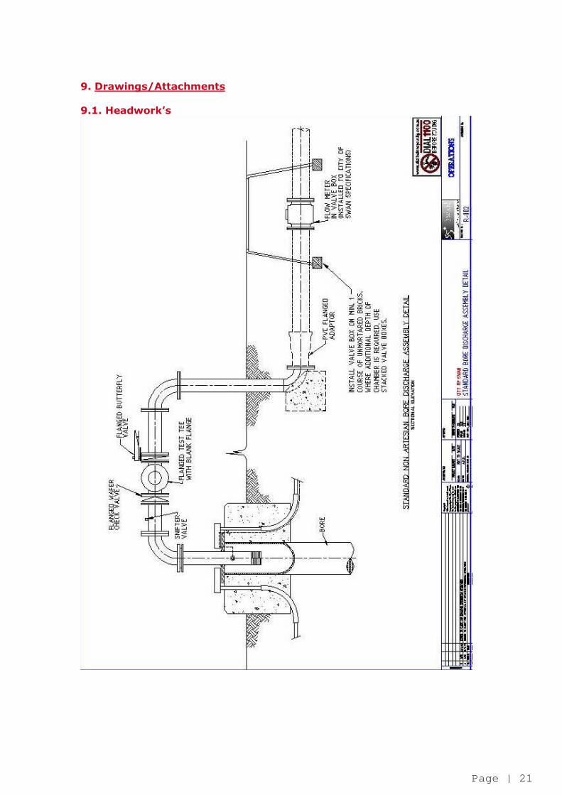
3.2. Headworks
For the purpose of this specification, the term Headworks (Discharge Assembly) shall refer to the
pipework and associated components from the top of the bore casing through to the underground connection to the PVC mainline.
3.2.1. Components
The headworks or discharge assembly shall contain, as a minimum, the following key components:
• Wafer check valve of equal diameter as piping; • Sniffer Valve (minimum 1”); • Flanged test tee with matching blank flange of equal diameter to piping; • Butterfly isolating valve (located after test tee).
All above ground pipework shall be constructed of hot dipped; galvanised Schedule 40 ERW fabricated steel and be butt weld flanged type, unless otherwise stated. All butt weld elbows shall be of the long radius type. The complete assembly shall be as per attached diagram.
3.2.2. Junction Boxes
• Two galvanised metal, electrical junction boxes are to be installed opposite each other on the top of the
first discharge assembly flange. • One box is to be for the pump supply cables, the other for the probe and drawdown tubes. • The pump electrical supply cable, 4 mm draw down tube and the two wire, low level probe wires, shall all
pass through Heavy Duty Electrical Grade electrical conduits (minimum diameter
• 32mm), installed in the concrete plinth and terminating in the junction boxes. • The probe wires, pump cable and draw down tube shall all pass through propriety glands or bushes
installed in the junction boxes. Cables passing through plain holes will not be accepted. • One junction box shall be equipped with a brass earth stud for the earthing of the assembly in accordance
with Western Australian electrical requirements.
3.2.3. Pressure Take Offs
A ¼ inch BSP tapping into the discharge pipe (near the point of connection to the mainline) shall be installed and connected to pressure tubing run to the electrical cubicle for attachment to relevant sensors.
3.3. Filtration
Any filtration systems shall be assessed individually at the time of submission for approval. The submission shall include detailed plans of the filtration system, including: make; model; size; layout; service life; and servicing requirements/costs.
4. Electrical Works
4.1. Power supply
A constant, underground, 415/240 Volt, 3-phase, 50Hz mains power supply for all cabinets associated with an irrigation bore and/or pump. Where a cabinet is installed for the sole purpose of supplying power to an irrigation controller only an Un-metered Power Supply may be established. This supply shall be maintained throughout the maintenance period and account ownership transferred to
the City of Swan as part of the Handover process of the site.

Page | 8
4.2. Electrical Cabinet/Cubicle
A standard City of Swan Irrigation Electrical Cubicle shall be installed at all sites having either a pump
system or irrigation controller installed, refer to 4.2.2 of these specifications.
4.2.1. Location
Electrical Cubicles shall be located so as to allow unobstructed access from a constructed road or car park, facing away from main irrigated area and orientated so as to ensure no direct water jet from surrounding sprinklers shall strike the cubicle.
Electrical cubicle shall be located within property boundary and no more than 30 metres from the bore or pump headworks, to allow for connection of flow meters, etc.
4.2.2. Cubicle Construction
All Cubicles shall be constructed to be totally enclosed, air insulated and manufactured from a minimum
2.5 mm thickness, marine grade aluminium alloy (Comalco 5152/H34 or equivalent) with all seams welded and ground smooth, finished with a orbital sanded finish and coated with transparent anti-graffiti paint. It shall be rigidly constructed with dimensions to comfortably accommodate the necessary equipment (preferred size is 550 mm deep X 930 mm wide X 1200 mm high). Lockable door(s) shall be fitted, with captive stays (one top and one bottom of each door) that hold them open at 100o against the wind. The internal side of the front door shall be fitted with a document holder. Doors shall be adequately stiffened to achieve rigidity and be fitted with two padlock lugs to enable the fitting of two Lockwood Night latches, fitted with City of Swan “P” keys for access. Cubicles shall be complete with a sun shield, raised at the front and sloping toward the rear with a ducted
vent installed in the top of the cubicle with 20 mm clearance from the sun shield and shall not exceed 1475 mm in height, including base, sun shield and channel, unless approved by the City of Swan. Cubicles shall be equipped with wiring channels of ample dimensions and generous access for internal wiring. They shall be mounted on a galvanised channel iron base, with gaskets, which are continuous and effectively exclude dust, secured in channels without the need for adhesive (including the door(s)). Cubicles shall have weather lips, bowed at the top and ventilators which provide the cooling requirements (particularly to the starting equipment) and have a minimum protection rating of IP 55. Bottom vents shall be fitted with deflector plates and screened with fly wire mesh. Construction should be such that access to internal wiring by dismantling the escutcheon and cover plates is readily possible without the removal of the door(s).
4.2.2.1. Base
Cubicle shall be secured with 316 stainless steel “Chemset” anchor bolts to a concrete plinth, min. 20 Mpa strength. The top of the plinth shall be set 100 mm above finished ground level and extend a minimum of 600 mm
below finished ground level. The top of the plinth shall extend beyond the cubicle by at least 100 mm on all sides and shall angle away so as to prevent the accumulation of water against the base of the cubicle. Conduits shall be installed in the concrete base so that they enter the cubicle behind the control panel. Additional spare conduits, two X 50 mm, and, two X 25 mm, shall be installed and fitted with long radius bends. Conduit stubs shall be extended at least 100 mm beyond the concrete plinth and terminate within a cable pit.

Page | 9
4.2.3. Aerial Pole All electrical cabinets associated with irrigation control shall have an 80mm (Diameter) x 6.5 metre (Height) Medium Duty Galvanised Steel Pole installed between a minimum of 2 metres and a maximum of 20 metres from the cubicle. This pole shall be installed so as to minimise obstruction in the area and maximise communication signal
strength as per this specification.
4.3. Electrical Components
4.3.1. Switch Board
The cubicle shall contain a minimum of:- • Main Switch
• Supply and Other Circuit Fuses • Motor Starter • Two (2) General Power Outlets (GPO) • A Rainman Mps Irrigation Controller as per below Specifications • Ammeter • Western Power Corporation Meter Panel • A Mainline Pressure Gauge • Hour Meter
Bore pumps are to have a minimum of the following protection:
• Phase Failure Relay
• Motor Manufacturer’s Recommended Overload Relay • Low Water Level Detected By Two Wire Probe in Bore
4.3.2. Control Panel
The control panel shall be suitable for a prospective fault current of 9 kA and accommodate all control
and monitoring equipment for the operation of the irrigation pump and controller. The minimum standard for internal wiring is V75 stranded (1.5 mm2). All connections to the internal wiring shall be to a terminal strip, numbered to correspond with a schematic diagram. One, laminated, copy of the “As Constructed” wiring diagram is to be placed in the document holder placed inside the cubicle door and one additional copy is to be handed to the Superintendent. Wiring shall be neat and unobtrusive, cleated in vertical and horizontal runs and installed without any interposed joins. A labelled terminal strip (able to accommodate three valve wires) is to be provided, for the termination (and bridging if required) of the field valve wiring. This terminal strip is to be wired to the controller outputs. Labelled terminal strips are to be provided for the rain switch and low level probe terminations.
Cubicles associated with pump systems shall be fitted with fault indicator lights (which must indicate in bright sunshine), reset button(s) and manual off/auto switch. The ammeter shall be a minimum of 70 mm square and shall have a red line to indicate the full load current of the pump motor. The scale shall be such that the full load current shall be approximately at the middle of the scale.
4.3.3. Motor Starting Equipment
A Western Power Corporation approved soft starter capable of 12 starts per hour is to be installed. The starter and contactors shall:
• Be selected for electrical utilisation category AC36. • Have auxiliary contacts, as required, to provide the specified control and interlock functions. • Be equipped with auxiliary contacts of a minimum rating of six Ampere. If it is impractical to include • the required auxiliary contacts on the main contactor, an auxiliary relay may be installed. • Be provided with a pump rated circuit breaker.
Page | 10
• Comply with the requirements of Australian Standard Specifications as appropriate for contactors, starters, overloads, relays and so forth. Contactors, timers, relays and ammeter are to be housed in a dust proof enclosure or be protected by a well fitting escutcheon panel to the superintendent's satisfaction. The escutcheon panel shall be fabricated and aluminium hinged as per attached diagram (9.2). It shall be fitted with at least two lifting handles. It shall be provided with cut-outs which expose only toggles and dollies.
4.3.4. Fault Current Limiters Fault current limiters shall be incorporated, where necessary, to limit the prospective fault current to a value within the capacity of the equipment being protected and be clearly labelled “Fault Current Limiters,” together with the make, type, rating and catalogue number of the limiter on the label.
4.3.5. Circuit Breakers Miniature over current circuit breakers, if required, shall be a minimum of 6KA rated and comply with the requirements of AS 3111 and/or AS 2184, as applicable. They shall be DIN rail mounted and fitted with suitable covers, if required by the Superintendent.
4.3.6. Residual Current Devices Residual current devices shall be installed and shall comply with AS 3190 and have a sensitivity of 30 mA.
4.3.7. Switches and Isolators All switches and isolators shall comply with AS 3133, class “M” or “X” as applicable and be suitable for their intended use and be mounted in accessible positions. Contacts shall have a minimum 10 Ampere rating.
4.3.8. Voltage Transformer A 240 Volt to 24 Volt transformer is to be provided to power the controller and other equipment as required. Transformers shall be a minimum rated 100VA and be double wound type with an earth screen interposed between the primary and secondary windings.
They shall be enclosed, A-N type with coils either vacuum impregnated using varnish to BS 2778 or resin encapsulated. All transformers shall be acceptable by the controller manufacture for both type and location.
4.3.9. Pump Circuit Breaker
Motor Pump Circuit Breakers shall be thermal type and provided in each phase and as approved by the motor manufacture for the protection of the motor in its installed situation. Circuit Breakers shall be compensated for ambient temperature and if of the adjustable type, have a minimum adjustment from 70 to 105% of full load current.
4.3.10. Push Buttons
Push button units shall be rated for their intended duty and be of the same manufacture and pattern throughout. They shall be of dust proof and oil tight pattern, of robust construction and have dust tight gaskets fitted where they protrude through panels. If required, they shall have corresponding “on/off” buttons mounted adjacent at a convenient position on the front of the panel. All push buttons shall be fitted with self-aligning, double break butt type contacts.
Page | 11
4.3.11. Indicating Lights
“Run” and “Trip/Overload” lights shall be an LED type that can be clearly viewed from a wide angle and be grouped in a uniform manner with respect to the push buttons. “Run” lights shall be Green in colour and operate when the pump is running. “Trip/Overload” lights shall be Amber in colour and operate due to:
• high temperature; • earth leakage; • more than 12 start attempts • motor overload
any other electrical fault.
4.3.12. Controller A Micro Control Engineering Rainman Mps controller is to be supplied and installed as per this specification. The inputs/outputs shall be direct connected to the controller.
4.3.13. Fans/Heaters
All cubicles are to be provided with a cooling fan. The fan shall be of the sandwich type and be sized to be able to expel the volume of air in the cubicle at
least four times per hour. The fan shall be installed directly under the top vent and shall be thermostatically controlled. Cubicles exposed to condensation shall have one “Helois” 70 watt, anti condensation heater, per 2m3, located near the bottom of the cabinet and thermostatically controlled.
4.3.14. Surge Suppression
All equipment shall be designed, suitable for withstanding any over-voltage which might develop in the installation, be equipped, where necessary, with suitable non-liner resistors (surge diverters) to attenuate the effects of over voltages and comply with the relevant Australian Standards.
4.3.15. Interference
The installation shall also include equipment, if necessary, that limits voltage fluctuations and harmonics. All equipment shall be designed not to emit electro magnetic interference, or shall be equipped with electro magnetic interference suppression. If necessary, equipment shall be equipped with radio frequency filtering (RFI) to ensure that radio and television reception is not interfered with near the site.
4.3.16. Earthing
The earthing of the installation shall be arranged for the Multiple Earthed Neutral system, comply with Australian Standards wiring rules AS 3000 and any additional requirements of the Supply Authority. Earthing shall be by “Copperweld” earth electrode driven to a depth of 2.5 metres in a FC4 main earth pit or similar, installed outside the cubicle and preferably in the wetted zone of the sprinklers. It shall have copper earthing conductors and bond all metallic water pipes and so forth within 2.5 metres of the installation. Earthing shall also effectively earth all metallic escutcheons, doors and so forth and incorporate an earth busbar or link(s), sized to suit all earth conductors.
4.3.17. Cable Pits
Cable pits shall be provided where straight conduit runs exceed 100 metres in length, or at changes in direction of a conduit run. Pits shall be of glass-fibre reinforced concrete moulded type, FCI manufacture

Page | 12
or similar and have lift off covers with cast-in lettering “Electric Cables” or similar. They shall have two 50 mm diameter (minimum) drainage holes drilled in the bottom and be set level and flush with finished ground surface.
4.3.18. Labelling
All electrical components shall be labelled as to their designation and function. Labels shall be manufactured from “Traffolyte” or similar material, fitted to the front of each panel and secured to the equipment using at least two chrome plated, round head screw fixings which will permit ready replacement. Labels shall be machine engraved with minimum three (3) mm high characters. “Danger” labels shall be red lettering (6 mm min.) on white background. Main Control Labels shall be black lettering (6 mm min.) on white background.
4.3.19. As Constructed Drawings The Contractor shall provide two sets of “As Constructed” drawings of all control and protection circuits together with all information necessary for the operation, maintenance and replacement of equipment. Plans should include the conduit allocation and direction of all conduits. One set of these documents shall be housed in the door pocket, one set handed to the Superintendent at handover.
4.3.20. Operation
The bore motor can be manually started by selecting “Manual” position on the selector switch. In order for the bore motor to be controlled automatically by the irrigation controller, the “Auto” position
must be selected. A key lockable isolation switch shall be installed to permit future “tagging” during repairs or maintenance.
5. Irrigation System
5.1. Design City of Swan Irrigation systems shall be designed to utilise the key components as identified in this specification in order to ensure uniformity with other City of Swan irrigation systems. This is required to minimise all costs and availability associated with spare parts. All irrigation systems shall be designed to hydro-zoning principles. Sporting Ovals shall be divided into two zones, active and passive.
The active area shall be the playing surface and shall be valved and have sprinklers installed separately to any passive area. For non sporting ovals (Passive Parks) the turf and garden areas are to be design to be irrigation separately.
5.1.1. Efficiency
Irrigation systems shall be designed so as to maximise the coefficient of uniformity to enable optimal watering efficiency. The theoretical distribution uniformity (DU) shall be supplied as part of all irrigation plans submitted. Systems shall be capable of meeting plant water requirements by operating only between the hours of 10 pm and 6 am, for a maximum of five (5) days per week, where practicable. Licensing requirements currently dictate no watering is to occur between the hours of 9 am and 6 pm daily.
5.1.2. Stations Irrigation systems shall be designed so as to ensure a single use for each station, for example: turf only; gardens only; tree bubblers only.

Page | 13
Each individual station shall be designed for the use of one single method of delivery, i.e. one type of sprinkler, no mixed stations shall be accepted. NOTE: Tree bubblers are intended to be used for newly planted trees up to a maximum of two years from practical completion before being phased out due to establishment of the planted trees. All tree bubblers shall be installed as separate stations. Under no circumstances are tree bubblers to be installed as part of a sprinkler line.
5.1.3. Format Proposed Irrigation System plans shall be submitted to the City of Swan in both hard copy and electronically utilising CAD based software. “As Constructed” Irrigation System plans shall also be provided within three months of the practical completion date of the specific site.
5.2. Conduits
Piping or cabling to be installed under existing or future roadways or pathways shall be installed within PVC sleeving and be constructed of SWJ PVC Pipe as required by these specifications. Separate conduits shall be installed for piping and cabling, at no point shall cabling and piping be permitted within the same conduit. PVC sleeving shall be of a size at least 30% larger than the outside diameter of the pipe coupling and/or cabling to be installed within it, continue a minimum of 600mm past the finished edge of the roadway or pathway and be of sufficient depth to ensure a minimum of 600mm depth from finished ground level. Any such conduits shall be clearly marked and identified on “As Constructed” plans.
5.3. Mainlines For the purpose of this specification the term “Mainline” shall refer to all pipework and associated fittings up to but not including the Solenoid Valve Assembly.
5.3.1. Mainline Pipes All underground mainlines shall be constructed of a minimum of Class 12 uPVC Piping. Piping of 80mm size or larger shall Class 12 PVC RRJ (Rubber ring joint) as a minimum. Piping up to and including 50mm in size shall be Class 12 PVC SWJ (Solvent weld jointed). All mainlines shall be jointed strictly in accordance with the manufacturers specifications.
5.3.2. Mainline Fittings All mainline fittings up to and including 50mm in size shall be Class 18 moulded pre-fittings and be solvent cement jointed. Mainline fittings 80mm or larger in size shall be as follows:
• Bends less than 90° angle shall be PVC rubber ring jointed long radius.
• Bends or elbows of 90° angle shall be Rubber Ring Joint, Ductile Iron. • All tees are to be Rubber Ring Joint, Ductile Iron. • All reducers to be concentric, Rubber Ring Joint, Ductile Iron. • Flanged connectors are to be Rubber Ring Joint, Ductile Iron or PVC with galvanised
backing ring. All Flanges are to be pre-drilled Table E Flanges.
5.3.3. Mainline Isolation Valves
Mainline isolation valves shall be installed at all significant changes in direction, each side of road crossings and every 500 metres on straight lines.

Page | 14
Isolation valves shall be Ductile Iron, resilient seated gate valves (with spindle and configured for clockwise turning to close valve) and be of equal size to the mainline in which they are installed. Where mainlines are 50mm or smaller isolation valves shall be Philmac nylon ball valves of equal size to the mainline in which they are installed. All valves shall be installed within a valve box and marked as required by this specification.
5.3.4. Air Release Valves Air release valves shall be fitted at end of lines and at identified high points in the installation. When installed on mainlines up to and including 50mm the valve shall be a 1” Philmac dual action Air Release valves. For mainlines 80mm and larger air release valves shall be 2” Philmac dual action air release valves. All air release valves shall be installed as per attached diagram utilising brass tapping band, Philmac nylon isolating ball valve and Philmac nipple.
All valves shall be installed within a valve box and marked as required by this specification.
5.3.5. Thrust Blocks
Concrete thrust blocks shall be installed on all Rubber Ring Joint fittings and as required on mainlines, including: elbows, bends, reducers, tees and isolation valves. Thrust blocks will not be required for “self-straining” fittings such as those fitted “inline” and tapping bands. Thrust blocks shall be constructed symmetrically about the centre line of the fittings and shall be placed so as all pipe joints are accessible for inspection and/or repair. Pipe, fittings and cabling shall be covered with a protective membrane of plastic sheeting when adjacent to concrete surfaces. Thrust blocks shall have minimum dimensions of approximately 600mm by 600mm by 600mm and with
all sides being either formed or placed against undisturbed soil faces to ensure clean edges. Concrete shall be minimum 20 mPa and be thoroughly mixed prior to installation. Dry concrete mix and water shall not be mixed in the trench.
5.3.6. Installation requirements Mainlines shall be installed so as to ensure a minimum of 450mm soil covering between the top of the mainline and the finished soil surface, with the exception of pipes under roadways, where the minimum covering depth shall be 600mm.
Pipes shall be laid into trenches having a continuous, firm and relatively smooth base, free of rocks, rubble or sharp objects. When installed in areas that cannot meet this requirement the pipe shall be bedded onto and covered with a minimum 100mm layer of sand to avoid any pipe contact with rocks, rubble or sharp objects. Trenching shall be straight and of a width sufficient to enable a minimum of 100mm space between any additional pipes installed within the same trench. Under no circumstances shall separate pipes touch within the trench. All trenches shall be filled with the excavated soil and be plate compacted after filling to minimise any potential subsidence in the future. No debris (off cuts of pipe, etc…) shall be buried in trenches during the construction of the site.
5.4. Cabling Conventional Type Cabling
Conventional field wiring of all irrigation systems shall consist of multi wire systems and include a minimum of two spare cables or ten percent of the total number of stations, whichever is greater, run from the controller to the furthest point of each mainline.
Page | 15
Two Wire Type Cabling Two wire decoder systems shall be utilised only with the express written consent of the City of Swan.
5.4.1. Size and Type for Conventional Cabling All low voltage (24 Volt) solenoid control valves shall be Tyflo multi-strand copper conductors sheathed in polyethylene suitable for direct burial. inimum cable sizes shall be:
• Common Wires - 2.5mm2 conductor • Active Wires < 400m - 1.5mm2 conductor when cable run is shorter than 400 metres • Active Wires > 400m - 2.5mm2 conductor when cable run is longer than 400 metres
in order to ensure reliable valve operation.
A different colour cable shall be used for each active wire, with an individual cable being installed to each valve. Common wires shall be black, spare wires shall be white. At each solenoid valve a minimum 1.5 metres loop of both common and active wires shall be installed neatly within the valve box to allow for future works. Cabling shall be run in conjunction with mainline installation and shall be neatly bundled and taped at approximately 4 metres intervals. Care should be taken to place cables below or immediately beside mainline without being taped to pipes. Where cabling is not run in conjunction with the mainline it shall be installed within PVC conduit as per conduit specifications.
5.4.2. Size and Type for Two Wire Cabling All Two Wire cabling shall be of 4mm suitable for direct burial type. Refer to 9.6 TWIN Field Cable Sizing chart to determine the cable size and length (km) required for a total number of decoders, (maximum 96 decoder per controller)
5.4.3. Connection for Two Wire Cable All Two Wire cable connection shall be within a marked value box using 3M DBY or DBR direct bury splice kits. All two wire paths shall NOT be looped and shall not create a closed circuit, instead it should be a continuous length of cable with tees sections where required.
Note: soldering of wire connections will not be accepted.
5.4.4. Connection for Conventional Cable
All field wiring cable connections, including solenoid valve connections, shall be made within a marked valve box using 3M DBY or DBR direct bury splice kits.
Spare wires shall also be terminated using the same direct bury splice kits. Note: soldering of wire connections will not be accepted.
5.4.5. Two Wire Decoders
All Two Wire Decoders shall be to Rainman Mps manufacture specification. A maximum of 96 decoders shall be permitted per Rainmain controller. Refer to 9.6 TWIN Field Cable Sizing chart to determine total number of decoders per cable length. No two (2) decoders shall be programmed with the same number; each decoder shall be identified individually.
Page | 16
5.4.6. Junction Boxes All cable joints or end of cable runs shall be made within a clearly marked and identifiable cable pit and shall have a minimum of 2 metres of spare cable looped neatly within the pit. These pits shall be identified on the “As Constructed” plans.
5.5. Solenoid Valve Assembly Solenoid valve assemblies shall be comprised of the following components;
• tapping band • polyethylene nipple(s) • electric/hydraulic solenoid valve
• PVC valve socket • PVC “Slipfix” fitting.
Bronze Tapping Bands shall be used to connect Solenoid Valve Assemblies to the mainline and shall be of equal size to the valve to which they will connect. Solenoid Isolation Valves shall be Philmac nylon ball valves of equal size to the solenoid valve. Connections between valves and tapping bands shall be made using threaded polyethylene nipples. All threaded connections shall be sealed with the use of PTFE Thread sealing tape. Electric/hydraulic solenoid valves shall be normally closed 24 Volt (AC), 50 cycle, Bermad 200 series (including flow control) or Bermad 400 series only, and shall include a manual bleed facility. A Flo span “slip fix” repair coupling of equal size to the valve, shall be jointed to a Cat 17, PVC valve socket (Cat 17) to allow for future servicing requirements.
Solenoid Valve assembly shall be installed as per attached diagram.
5.6. Valve Boxes
All valves, including: mainline isolation valves; air release valves; solenoid isolation valves; solenoid
control valves, shall be installed within a lockable valve box. Mainline Isolation valve boxes shall be HR Products “Jumbo” Valve Box, Model 1420-12VBHR (or approved similar). Solenoid Valve & Air Release Valve boxes shall be HR Products Model 1419-12VBOL (or approved similar) without pipe portals and with overlay style lockable lids with stainless steel locking bolts. Valve Boxes shall be installed so as to have the overlay style lid finishing flush with the final soil level and shall ensure valves are readily accessible for servicing without removal of box as per the attached diagram. All valve boxes shall have a 3M Orange ball marker installed between the valve and the lockable lid to facilitate future locating requirements.
5.7. Lateral Lines For the purpose of this specification, lateral lines shall refer to all pipelines and associated fittings downstream from the Solenoid Valve Assembly, up to but not including, the sprinkler and its riser.
5.7.1. Pipes
Lateral lines shall be constructed of a minimum of Class 9 uPVC Piping. All joins in pipework and fittings shall be by Solvent Weld Joint (SWJ) and shall be constructed strictly in accordance with the manufacturer’s specifications. This includes the cleaning of all sized joints with approved primer prior to jointing.
5.7.2. Fittings All lateral line fittings shall be Class 18 moulded pre-fittings and be solvent cement jointed, in accordance with manufacturer’s specifications. Any excess solvent cement shall be wiped clean from pipes and fittings.

Page | 17
5.7.3. Installation Requirements
Lateral Lines shall be installed so as to ensure a minimum of 300mm soil covering between the top of the lateral line and the finished soil surface, with the exception of pipes under roadways, where the minimum covering depth shall be 600mm. Pipes shall be laid into trenches having a continuous, firm and relatively smooth base, free of rocks, rubble or sharp objects. When installed in areas that cannot meet this requirement the pipe shall be bedded onto and covered with a minimum 100mm layer of sand to avoid any pipe contact with rocks, rubble or sharp objects. Trenching shall be straight and of a width sufficient to enable a minimum of 100mm space between any additional pipes installed within the same trench. Under no circumstances shall separate pipes touch within the trench. All trenches shall be filled with the excavated soil and be plate compacted after filling to minimise any potential subsidence in the future.
5.8. Sprinklers
In order to maintain a standardised irrigation network across the City of Swan this specification provides a standard range of sprinklers to be utilised when designing irrigation systems. Any use of sprinklers outside of those listed may be approved with the express written consent of the
City of Swan at the time of assessment. Sprinklers shall be full circles where required and adjustable or part circle on edges. Adjustable sprinklers (adjusted to full circle) shall not be installed where a full circle sprinkler is required.
5.8.1. Size and Type
The following gear driven sprinklers shall be utilised as required:
• Hunter I-41 Series - o I-41: 9 cm pop up (Full Circle or Adjustable) sprinkler
• Hunter I-35 Plus Series - o I-35: 9 cm pop up (Full Circle or Adjustable) sprinkler
• Hunter I-20 Ultra Series - o I-10: Shrub (Full Circle or Adjustable) Sprinkler o I-20: 10 cm pop up (Full Circle or Adjustable) sprinkler (Stainless steel riser) o I-20-6P: 15 cm pop up (Full Circle or Adjustable) sprinkler (Stainless steel riser) o I-20-HP: 30 cm pop up (Full Circle or Adjustable) sprinkler
• Hunter PGJ Series -
o PGJ - 00: Shrub (Full Circle or Adjustable) sprinkler o PGJ - 04: 10 cm pop up (Full Circle or Adjustable) sprinkler o PGJ - 06: 15 cm pop up (Full Circle or Adjustable) sprinkler o PGJ - 12: 30 cm pop up (Full Circle or Adjustable) sprinkler
The following spray type sprinklers shall be utilised in smaller areas as required:
• Toro 570 Series – o 570Z-S: Shrub Adaptor o 570Z-3P: 75 mm pop up sprinkler o 570Z-4P: 100 mm pop up sprinkler o 570Z-6P: 150 mm pop up sprinkler (No side inlet) o 570Z-12P: 300 mm pop up sprinkler (No side inlet)
Toro MPR Plus spray nozzles shall be utilised with Toro 570 sprinklers. Toro 500 Series Flood Bubblers or approved equivalent, on 15mm poly risers, shall be utilised for tree bubblers. All sprinklers available with non-drain valves as an option shall have such valves installed. Sub surface or drip irrigation may be utilised in garden bed areas depending of water quality and with the written consent of the City of Swan.
5.8.2. Risers

Page | 18
All Sprinklers shall be installed on adjustable articulated risers, consisting of 3 threaded poly elbows and a straight poly riser, of equivalent diameter to the inlet thread size of the sprinkler. Length of the articulated risers shall be sufficient to ensure the riser is inclined at an angle of 45o to the horizontal when installed is complete. “Funny” pipe (Olsen EZ-EL or similar) may be used for spray type sprinklers only, as required and shall at no time be utilised for gear driven sprinklers.
5.8.3. Height and Adjustment
Sprinklers shall be set as per attached diagram with the top of the sprinkler being set flush with finished ground level, as per manufacturer’s specifications. Sprinklers should also be set straight to the vertical alignment, except when installed on significant
slopes where the sprinkler shall be set halfway between the vertical and the angle of the slope on which it is installed. When installed beside roadways or footpaths, sprinklers shall be installed so as to be 150 mm from the nearest kerb line. Sprinkler arcs shall be adjusted to ensure minimal overspray onto nearby roadways or fixtures occurs.
6. Irrigation Control System
The City of Swan operates a centrally controlled Irrigation network to monitor its irrigation operations throughout the City. All new systems installed by the City, or to be taken over by the City (eg new developments) are to be constructed as per the following specifications. Practical completion dates shall not be considered effective until the controller is communicating to the City of Swan Central Irrigation Control System.
6.1. Controller
All irrigation systems shall be operated by a Rainman Mps controller as manufactured by Greenspan and shall include inputs for all required components to fulfil the required specifications as detailed below. The controller shall be capable of operating the maximum number of stations and shall be housed with the electrical cabinet as per this specification.
6.2. Communications Equipment / Connection to Optical fibre network
All irrigation controllers shall be connected to the City of Swan Central Irrigation Control System via radio modem by the date of practical completion. The radio transmitter/receiver shall be an RF Innovations Allegro tuned to 471.85 frequency and
connected to a pole mounted RF Industries YB 66 antennae via RF Industries RG 58C communications cabling. The antennae shall be installed so as to maintain a reliable signal and be as unobtrusive as possible. All communications equipment shall be compliant with relevant Australian Communications Authority regulations. All radio equipment shall be installed neatly within the cabinet and secured, so as to ensure no loose cabling or other components within the cabinet.
6.3. Sensors
All Irrigation control systems shall include the following sensors to be installed and connected to the controller: Pressure Transducer – Danfoss MBS3000, to be installed within the cabinet to pressure tubing from the mainline (as per headworks specifications).
Rain Sensor – Hunter Mini Clik, to be pole mounted on the aerial pole. Current Transducer – 253 TALW LSHG, to be installed within the electrical cabinet.
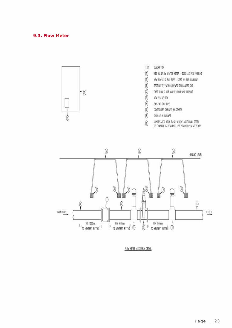
6.4. Flow Meters

Page | 19
All bores and/or ground water sources used for irrigation and/or other purposes shall be fitted with a City of Swan approved flow meter. Listed are some flow meters that maybe approved by the City of Swan.
• Emflux I300 Magnetic Flow meter • Arad Octave Ultrasonic flow metre • Bermad Pulse Hydrometer
The approved flow meter shall be required to communicate with the City of Swan Central Irrigation
Control System. All flow meters shall be installed as per the manufactures specifications and a testing tee configuration as shown within clause 9 Drawings/Attachments sub clause 9.3 Flow Metre.
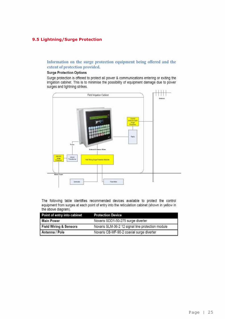
6.5. Lightning/Surge Protection
All irrigation components that communicate directly with the controller unit onsite (Rainman Mps) shall be protected by a lightning/surge protections system. The attachment diagram in clause 9 Drawings / Attachments sub clause 9.5 Lightning/Surge Protection illustrates the required protections. Mains Power: Novaris SDD1-50-275 surge diverter Field Wiring & Sensors: Novaris SLM-36-2 12 signal line protection module Antenna / Pole Novaris CB-MF-90-2 coaxial surge diverter
6.6. Central Irrigation Control System Connection
Upon commissioning of all irrigation systems it shall be compulsory to allow for connection of the site to the City of Swan Central Irrigation Control System and that all functions, including communications and reporting, are fully functional and verified by the City of Swan. Practical completion dates shall not be considered effective until connection to the central system is completed. This connection is to be maintained throughout the contractor’s maintenance period prior to hand over to
the City of Swan.
7. Commissioning 7.1. As Constructed Plans
“As Constructed” Irrigation System plans shall be provided to the City of Swan within three months of the practical completion date, in both hard copy and electronically in DXF file format. A copy of the “As Constructed” electrical plans, bore construction details and flow test results shall also be supplied at this time. Upon handover to the City, these drawings are to be resubmitted to the City of Swan as stated in clause 8, Handover Procedure to the City of Swan.
7.2. Training Site specific training, relating to any particular areas of maintenance shall be supplied to City of Swan upon request at the time of handover to the City. An example of this may be a specific filtration system or other such component of the irrigation system to which the City of Swan staff may not be familiar.
8. Handover Procedure to City of Swan
A formal handover procedure is required by the City of Swan. There are certain irrigation requirements that will form part of this procedure, prior to acceptance of any the irrigation system by the City. Any changers to the irrigation system during the maintenance period by the Developer will need to be
recorded in the appropriate drawings or information sheet.

Page | 20
This information shall be forwarded to the City during handover procedure. Further information on each component is explained in this clause.
8.1. Water Allocation
All irrigation systems that abstract ground water as its main water source within the City Of Swan, shall have a Water Allocation Entitlement as per the Department of Water regulations. The Water Allocation shall be transferred to the City of Swan on acceptance of handover by the City.
8.2. Transfer of Water Entitlements
The Water Entitlement transfer form that is provided by the Department of Water known as (Form F Application for the Transfer of Water Entitlements) shall be provided at handover acceptance by the City. This form shall be completed, signed by the authorised person and provide a payable cheque or other payment methods to the Department of Water for the amount stated on the Application for the Transfer of Water Entitlement form.
8.3. Bore Construction Details
All details in the construction of a bore within the City of Swan will be required to be forward on handover acceptance by the City. These details will need to provide all the specifications in the pumps, bore’s, headwork’s construction and any changers that may have been undertaken during the maintenance period by the Developer. These changes will need to be highlighted for future reference and ongoing maintenance.
8.4. Bore Service and Logs
Prior to handover acceptance by the City of Swan, all bore’s that are intended to be handed to the City, shall be serviced by a registered service provider. All bore log details that form part of this service shall be provided to the City.
8.5. Irrigation Pump Service
Prior to handover acceptance by the City Of Swan, all irrigating pumps and all associated equipment shall be serviced and returned to the manufacture specifications. All service details that form part of this service shall be provided to the City.
8.6. As Constructed Drawings
All “As Constructed” drawing shall be provided to the City at handover. These drawing will need to include any changers that may have been undertaken during the maintenance period by the Developer. These changes will need to be highlighted for future reference and ongoing maintenance.
Page | 21
9. Drawings/Attachments 9.1. Headwork’s

Page | 22
9.2. Electrical Cubicle
1. SOLENOID TERMINAL STRIP
2. AUTO OFF/MAN KEY (KEY REMOVABLE IN OFF ONLY) 3. GREEN PUMP RUN LIGHT 4. AMBER OVERLOAD LIGHT 5. LAMP TEST BUTTON 6. AMMETER (72 x 72) 7. 10 AMP DIN G.P.O. (4SO10) & 10 AMP R.C.D. MCB 8. T100F MAIN SWITCH 9. MICRO CONTROLLER (WITH 10 AMP G.P.O. MOUNTED BEHIND ESCUTCHEON)
NOTES: 1. STARTER TO BE SOFT START TYPE (D.O.L. IF ALLOWABLE) 2. ALL PRESSURE CUT OUTS TO BE THROUGHT MICRO CONTROLLER
VIA 0-10 BAR, 4-20 MA CURRENT TRANSDUCER 3. PUMP CURRENT MONITORING THROUGH MICRO CONTROLLER VIA 4-20 MA CURRENT TRANSDUCER 4. LOCKS TO BE CITY OF SWAN “P” KEYED WITH NIGHT LATCHES 5. FULL HEIGHT PAN WELDED TO REAR OF CUBICLE 6. WESTERN POWER FULLY SEGREGATED BEHIND PANEL 7. THUMB SCREWS TO BE USED ON BOTH ESCUTCHEONS
Page | 23
9.3. Flow Meter

Page | 24
9.4. Air Release, Mainline Isolation , Flushing Valve, Solenoid Valve Assembly & Sprinkler Installation
Page | 25
9.5 Lightning/Surge Protection

Page | 26
9.6 TWIN Field Cable Sizing
TWIN Field Cable Sizing
LP Solenoids (2W) HP Solenoids (5W)
Max. No. Solenoids/Grouping
on at once
Cable Size
(mm²)
50 Decoders
max length (km)
96 Decoders
max length (km)
50 Decoders
max length (km)
96 Decoders
max length (km)
1 6 6.6 4.0 4.2 3.0
4 4.2 2.7 2.8 2.0
2 6 4.8 3.2 2.7 2.1
4 3.2 2.1 1.6 1.4
4 6 3.1 2.4 1.5 1.3
4 2.0 1.6 1.0 0.8