irrigation flow monitor and control system, version 1rick.sparber.org/electronics/fmc.pdf · ·...
TRANSCRIPT
R. G. Sparber January 7, 2018 Page 1 of 125
Irrigation Flow Monitor and Control System, Version 1.4
By R. G. Sparber Protected by Creative Commons.
1
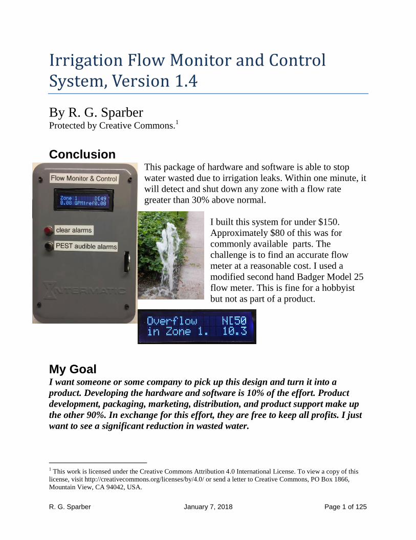
Conclusion This package of hardware and software is able to stop
water wasted due to irrigation leaks. Within one minute, it
will detect and shut down any zone with a flow rate
greater than 30% above normal.
I built this system for under $150.
Approximately $80 of this was for
commonly available parts. The
challenge is to find an accurate flow
meter at a reasonable cost. I used a
modified second hand Badger Model 25
flow meter. This is fine for a hobbyist
but not as part of a product.
My Goal I want someone or some company to pick up this design and turn it into a
product. Developing the hardware and software is 10% of the effort. Product
development, packaging, marketing, distribution, and product support make up
the other 90%. In exchange for this effort, they are free to keep all profits. I just
want to see a significant reduction in wasted water.
1 This work is licensed under the Creative Commons Attribution 4.0 International License. To view a copy of this
license, visit http://creativecommons.org/licenses/by/4.0/ or send a letter to Creative Commons, PO Box 1866,
Mountain View, CA 94042, USA.

R. G. Sparber January 7, 2018 Page 2 of 125
Background I own a very smart Irrigation Controller from RainBird. It is aware of the weather
and adjust the run time of each of my 6 zones accordingly.
However, this controller is missing an important
feature:
the ability to monitor and act on flow rates.
If a valve sticks closed or open it can't tell. If a pipe
bursts, it can't tell. If a single "spaghetti line" blows its
emitter, can't tell. Worse yet, I can't quickly shut off the water.
All of that changed with my Flow Monitor and
Control (FMC) installed.
See https://www.youtube.com/watch?v=fuf6UD6G-A8&t=94s and
https://www.youtube.com/watch?v=oRK1sAZ7rfI&t=73s for videos of the system
in action.
Up until now, I have compensated for the lack of automatic flow control by
manually recording my water usage on my city water meter. Since most of my
usage is due to irrigation, this does at least tells me something is wrong. I must
then sequence through all 6 zones and inspect the area of the property until I find
the one with the problem.
In one case, I had a major leak that left no water on the surface. My monthly bill
told me something was wrong when it indicated 20,000 gallons of unusual
consumption. That $300 bill was a big motivator for finding an automatic method
of dealing with flow problems.

R. G. Sparber January 7, 2018 Page 3 of 125
RainBird does sell a flow monitoring system but it is targeted for the commercial
market and is priced accordingly. The software can be found in Appendix 6, page
75.
This article presents the design of my system including system block diagrams,
schematics, flow charts, and software. It does not present the numerous dead ends
and re-writes needed to get to what was finally built.
I have included sufficient detail so someone with some hardware background could
build the system. Minimal software knowledge is needed since I have supplied my
code. If requested, I can supply the binary file.

R. G. Sparber January 7, 2018 Page 4 of 125
User's Manual Under normal conditions, the user does nothing. If the
beeper sounds, the screen will tell the user which zone
has a problem and what is wrong.
If the Flow Monitor and Control was able to stop the
flow of a faulted zone, the user should inspect the zone,
correct the fault, and then clear the alarm.
If the flow cannot be stopped, the user should turn off
the main water supply. The problem will be between the
water meter's output and the valve's output. A broken
pipe will be obvious. If a valve is unable to shut down
you will see water flowing in the zone when the
controller says it is off.
System Normal When The Flow Monitor and Control is first
powered up, it records the average water use for
each zone. Here you see Zone 1 is active and the
flow is 4.54 Gallons Per Minute (GPM). These
measurements are saved as the first reference
flow2 when Zone 1 is turned off by the Irrigation Controller.
When a give zone is run again, its flow rate is
compared to the reference. In this case, the
current flow matches the flow the last time this
zone ran.
When no zones are on, the flow is compared to a
limit3 of 0.06 GPM. Flow less than 0.06 GPM is
considered acceptable.
2 It is therefore essential that each zone is initially in proper working order. See page 9 for how to audit each zone.
3 All readings are ± 0.03 GPM so this is the smallest limit we can have and not get false alarms.

R. G. Sparber January 7, 2018 Page 5 of 125
Fault Situations When no zones are on and the flow exceeds the
limit of 0.06 GPM, we get an Overflow condition
and a Major Alarm is sounded both day and night.
It will sound for 0.1 seconds and be quiet for 0.1
seconds. The number in the lower right hand corner
is the current flow. It is possible to see "Can't stop idle flow." with a current flow
of 0. This means it was greater than 0.06 GPM but is now zero.
If the new flow is more than 30% higher than the
reference, we get an Overflow condition. The
system responds by turning off the valve and
taking another flow measurement.
If the flow is stopped, the screen indicates the
problem. If it is daytime, the Flow Monitor and
Control sounds a Minor Alarm which is 0.3
seconds on and 2 seconds off. The flow that
triggered the alarm is in the lower right corner.
In this case, other zones can run and they will be monitored. If the flow can't be
stopped, a Major Alarm will sound. Any time an Overflowed zone with Minor
Alarm runs, its flow will be stopped.
If the Flow Monitor and Control was unable to
stop the flow4, the screen tells the story and a
Major Alarm is sounded. The current flow is in
the lower right corner.
In this case, the Irrigation Controller can run other zones but they will be blocked
as the Flow Monitor and Control continues to try and stop the leak. I have not yet
seen this fault but it would be extremely expensive to ignore.
4 6.80 GPM is 9,800 gallons per day!

R. G. Sparber January 7, 2018 Page 6 of 125
If the flow is more than 30% lower than the
threshold, we get an Underflow condition. The
second line shows the current flow and normal
flow (ref). If during the day, a Minor Alarm is
sounded.
If the underflowed zone is not active, the system
will monitor and control the other zones while
displaying the error message for the faulted zone.
Controlling Alarms
By pushing the "clear alarms" button, all alarms
will be cleared. If the problem is still present, the
alarm will come back after 70 seconds.
By pushing the PEST audible alarms button, any
audible alarm will be silenced. It is a pest so this
shuts it up. Alarms will return if the problem has not been resolved and cleared in
time. For a Major alarm, expect it to sound again in 15 minutes. Minor alarms will
sound again after 24 hours. Fault information will remain on the screen.
R. G. Sparber January 7, 2018 Page 7 of 125
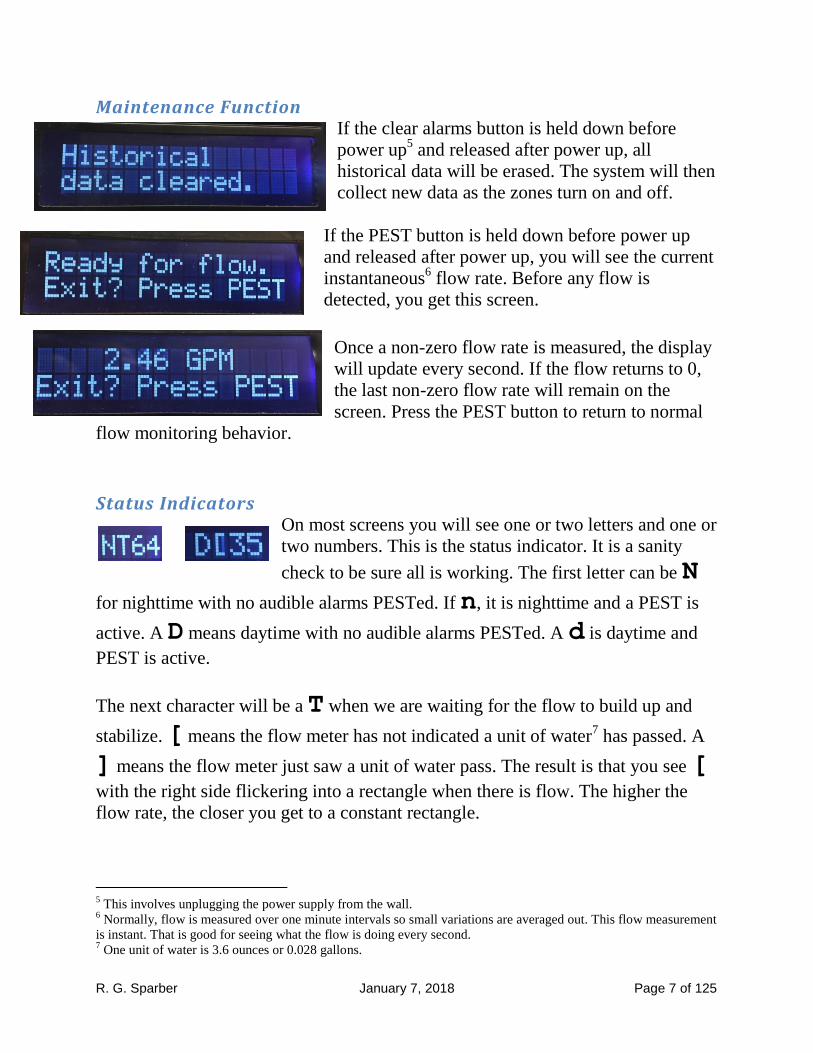
Maintenance Function If the clear alarms button is held down before
power up5 and released after power up, all
historical data will be erased. The system will then
collect new data as the zones turn on and off.
If the PEST button is held down before power up
and released after power up, you will see the current
instantaneous6 flow rate. Before any flow is
detected, you get this screen.
Once a non-zero flow rate is measured, the display
will update every second. If the flow returns to 0,
the last non-zero flow rate will remain on the
screen. Press the PEST button to return to normal
flow monitoring behavior.
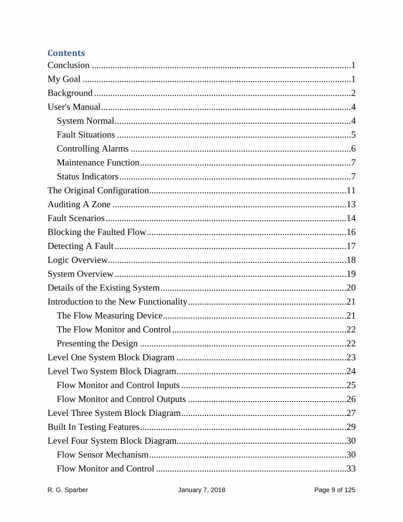
Status Indicators On most screens you will see one or two letters and one or
two numbers. This is the status indicator. It is a sanity
check to be sure all is working. The first letter can be N
for nighttime with no audible alarms PESTed. If n, it is nighttime and a PEST is
active. A D means daytime with no audible alarms PESTed. A d is daytime and
PEST is active.
The next character will be a T when we are waiting for the flow to build up and
stabilize. [ means the flow meter has not indicated a unit of water7 has passed. A
] means the flow meter just saw a unit of water pass. The result is that you see [
with the right side flickering into a rectangle when there is flow. The higher the
flow rate, the closer you get to a constant rectangle.
5 This involves unplugging the power supply from the wall.
6 Normally, flow is measured over one minute intervals so small variations are averaged out. This flow measurement
is instant. That is good for seeing what the flow is doing every second. 7 One unit of water is 3.6 ounces or 0.028 gallons.

R. G. Sparber January 7, 2018 Page 8 of 125
The two numbers are a countdown until a new flow measurement is
complete. If a zone just turned on, the count will go from 70 seconds
down to 60 and the T will precede the count. At 60 you will see [and the count
will decrement until it reaches 0. Then the flow information will update.
If the user chooses to manually operate more than
one zone at the same time, the flow is not
monitored.
There is an electromechanical relay inside the
Flow Monitor And Control that can fail. As long as
it is stuck in the open position, this message will
display and a Minor alarm will sound. However, if
the problem goes away, we will return to normal operation.
It is also possible that software errors will occur. This might be from real software
bugs or could be due to electrical noise crashing the Flow Monitor And Control. If
you get a software error message, please write it down. Then unplug power for 10
seconds and plug it back in. See if the problem returns. Any correlations with
zones turning on or off would be helpful in debugging the problem.
R. G. Sparber January 7, 2018 Page 9 of 125
Contents
Conclusion ................................................................................................................. 1
My Goal ..................................................................................................................... 1
Background ................................................................................................................ 2
User's Manual ............................................................................................................. 4
System Normal ....................................................................................................... 4
Fault Situations ...................................................................................................... 5
Controlling Alarms ................................................................................................ 6
Maintenance Function ............................................................................................ 7
Status Indicators ..................................................................................................... 7
The Original Configuration ......................................................................................11
Auditing A Zone ......................................................................................................13
Fault Scenarios .........................................................................................................14
Blocking the Faulted Flow .......................................................................................16
Detecting A Fault .....................................................................................................17
Logic Overview ........................................................................................................18
System Overview .....................................................................................................19
Details of the Existing System .................................................................................20
Introduction to the New Functionality .....................................................................21
The Flow Measuring Device ................................................................................21
The Flow Monitor and Control ............................................................................22
Presenting the Design ..........................................................................................22
Level One System Block Diagram ..........................................................................23
Level Two System Block Diagram ..........................................................................24
Flow Monitor and Control Inputs ........................................................................25
Flow Monitor and Control Outputs .....................................................................26
Level Three System Block Diagram ........................................................................27
Built In Testing Features ..........................................................................................29
Level Four System Block Diagram..........................................................................30
Flow Sensor Mechanism ......................................................................................30
Flow Monitor and Control ...................................................................................33

R. G. Sparber January 7, 2018 Page 10 of 125
Signal Converter Subsystem ................................................................................34
All Zones Off .......................................................................................................35
Pushbuttons ..........................................................................................................37
Light Sensor .........................................................................................................38
Flow Interface ......................................................................................................39
Power....................................................................................................................42
The Arduino .........................................................................................................42
The Liquid Crystal Display ..................................................................................48
The Full Schematic ..............................................................................................49
Bill Of Materials ..................................................................................................52
Software ...................................................................................................................53
Overall Software Strategy ....................................................................................54
Level 1 Flowchart ................................................................................................56
Major Subroutines ................................................................................................62
Software Structure................................................................................................64
Acknowledgements ..................................................................................................66
Appendix 1: Zero Crossing Pulse Width .................................................................67
Appendix 2: EEPROM Map ....................................................................................68
Appendix 3: Arduino Compilation Error Experiences ............................................69
Appendix 4: Anti-flicker ..........................................................................................71
Appendix 5: Test Cases............................................................................................72
Non-fault Cases ....................................................................................................72
Fault Cases ...........................................................................................................73
Appendix 6: The Code .............................................................................................75
R. G. Sparber January 7, 2018 Page 11 of 125
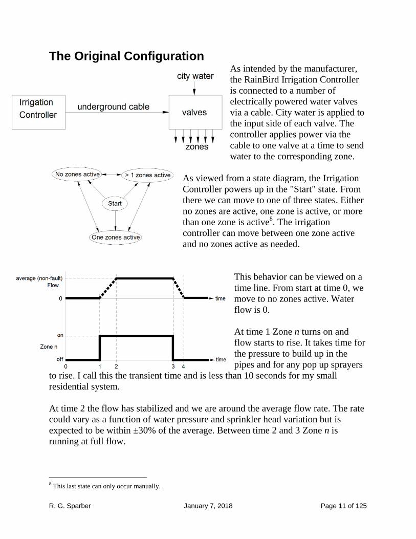
The Original Configuration As intended by the manufacturer,
the RainBird Irrigation Controller
is connected to a number of
electrically powered water valves
via a cable. City water is applied to
the input side of each valve. The
controller applies power via the
cable to one valve at a time to send
water to the corresponding zone.
As viewed from a state diagram, the Irrigation
Controller powers up in the "Start" state. From
there we can move to one of three states. Either
no zones are active, one zone is active, or more
than one zone is active8. The irrigation
controller can move between one zone active
and no zones active as needed.
This behavior can be viewed on a
time line. From start at time 0, we
move to no zones active. Water
flow is 0.
At time 1 Zone n turns on and
flow starts to rise. It takes time for
the pressure to build up in the
pipes and for any pop up sprayers
to rise. I call this the transient time and is less than 10 seconds for my small
residential system.
At time 2 the flow has stabilized and we are around the average flow rate. The rate
could vary as a function of water pressure and sprinkler head variation but is
expected to be within ±30% of the average. Between time 2 and 3 Zone n is
running at full flow.
8 This last state can only occur manually.

R. G. Sparber January 7, 2018 Page 12 of 125
At time 3 the zone turns off and the flow starts to drop. At time 4 the flow is back
to 0. This is the second transient time and is also less than 10 seconds. We just
transitioned from one zone on to no zones on.
R. G. Sparber January 7, 2018 Page 13 of 125
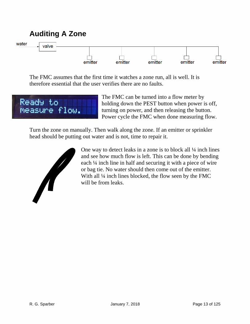
Auditing A Zone
The FMC assumes that the first time it watches a zone run, all is well. It is
therefore essential that the user verifies there are no faults.
The FMC can be turned into a flow meter by
holding down the PEST button when power is off,
turning on power, and then releasing the button.
Power cycle the FMC when done measuring flow.
Turn the zone on manually. Then walk along the zone. If an emitter or sprinkler
head should be putting out water and is not, time to repair it.
One way to detect leaks in a zone is to block all ¼ inch lines
and see how much flow is left. This can be done by bending
each ¼ inch line in half and securing it with a piece of wire
or bag tie. No water should then come out of the emitter.
With all ¼ inch lines blocked, the flow seen by the FMC
will be from leaks.
R. G. Sparber January 7, 2018 Page 14 of 125
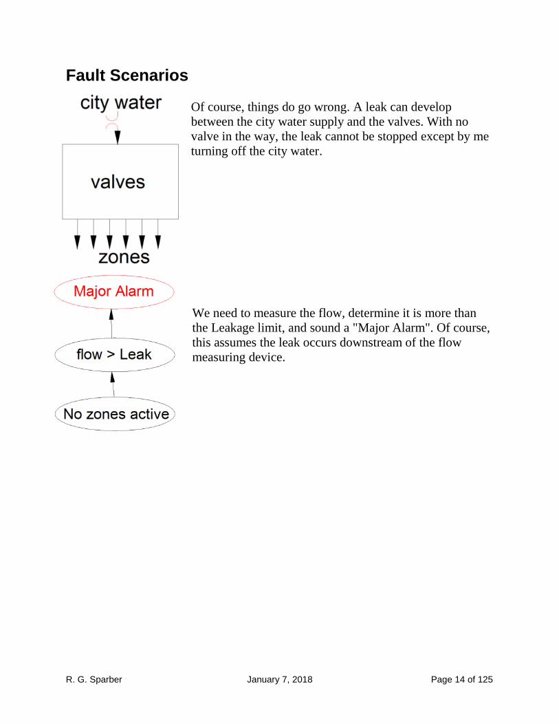
Fault Scenarios
Of course, things do go wrong. A leak can develop
between the city water supply and the valves. With no
valve in the way, the leak cannot be stopped except by me
turning off the city water.
We need to measure the flow, determine it is more than
the Leakage limit, and sound a "Major Alarm". Of course,
this assumes the leak occurs downstream of the flow
measuring device.

R. G. Sparber January 7, 2018 Page 15 of 125
More likely is a leak in a zone downstream from the valve.
As long as the zone is active, excess water will flow. But
when we return to having all zones off, the leak stops.
In this time line we start out the
same as the non-fault case. The zone
is initially off and the flow is 0. At
time 1 the zone turns on and the
flow starts to build. At time 2 the
flow is at the average. But at time 3
the flow builds up a second time.
Maybe a pipe burst or a sprinkler
head blew. We end up at a flow
more than 30% above average. At time 4 the controller turns off the zone, not
knowing that a fault has occurred. The flow then drops back to 0 at time 5.
R. G. Sparber January 7, 2018 Page 16 of 125
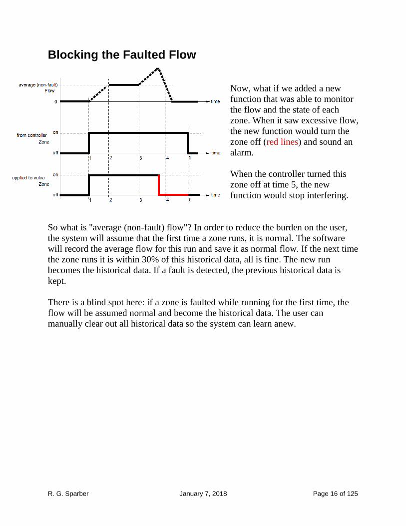
Blocking the Faulted Flow
Now, what if we added a new
function that was able to monitor
the flow and the state of each
zone. When it saw excessive flow,
the new function would turn the
zone off (red lines) and sound an
alarm.
When the controller turned this
zone off at time 5, the new
function would stop interfering.
So what is "average (non-fault) flow"? In order to reduce the burden on the user,
the system will assume that the first time a zone runs, it is normal. The software
will record the average flow for this run and save it as normal flow. If the next time
the zone runs it is within 30% of this historical data, all is fine. The new run
becomes the historical data. If a fault is detected, the previous historical data is
kept.
There is a blind spot here: if a zone is faulted while running for the first time, the
flow will be assumed normal and become the historical data. The user can
manually clear out all historical data so the system can learn anew.
R. G. Sparber January 7, 2018 Page 17 of 125
Detecting A Fault We do not want any false alarms but also do not want to miss faults. Experience
has taught me that normal flow can vary ± 25%. To avoid false alarms, we want
our limit to be greater than this variation. RainBird has their limit set at ±30%
which is reasonable9.
If a zone consists of sprinkler heads, the nominal flow will be much larger than
with drip but a blown head will pass more water too. I don't have any problem
detecting a blown head. However, a cracked riser could go undetected if it passes
less than 30% of the total.
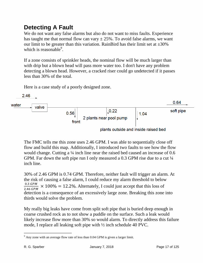
Here is a case study of a poorly designed zone.
The FMC tells me this zone uses 2.46 GPM. I was able to sequentially close off
flow and build this map. Additionally, I introduced two faults to see how the flow
would change. Cutting a ¼ inch line near the raised bed caused an increase of 0.6
GPM. Far down the soft pipe run I only measured a 0.3 GPM rise due to a cut ¼
inch line.
30% of 2.46 GPM is 0.74 GPM. Therefore, neither fault will trigger an alarm. At
the risk of causing a false alarm, I could reduce my alarm threshold to below
Alternately, I could just accept that this loss of
detection is a consequence of an excessively large zone. Breaking this zone into
thirds would solve the problem.
My really big leaks have come from split soft pipe that is buried deep enough in
coarse crushed rock as to not show a puddle on the surface. Such a leak would
likely increase flow more than 30% so would alarm. To directly address this failure
mode, I replace all leaking soft pipe with ½ inch schedule 40 PVC.
9 Any zone with an average flow rate of less than 0.04 GPM is given a larger limit.

R. G. Sparber January 7, 2018 Page 18 of 125
Logic Overview To address faults, we need to
1. monitor the flow on an active
zone
2. determine if it is too much
3. try to shut down the valve
4. check the flow again
5. determine if it is now less
than leakage
6. and sound an alarm
If closing the valve stopped the
flow, we call it a Minor Alarm.
Then we mark this zone so in the future it is prevented from running.
If, after we try to shut down the zone, the flow is more than leakage, we did not
stop the flow. It is then marked as a Major Alarm.
If the flow is too small, we call it Underflow and declare a Minor Alarm. The
plants are not getting enough water so shutting down the flow would only make
matters worse.

R. G. Sparber January 7, 2018 Page 19 of 125
System Overview Flow Monitoring and Control is not a new invention. Companies like RainBird sell
a similar function. They are used in application where a large amount of water
normally flows and one leak can be costly. The price of such a system is over
$1000 and I'm sure it pays for itself quickly. But in my little home irrigation
system, this price tag is out of the question. Mine cost around $150.
I will call this new function "George".
He sits between the Irrigation
Controller and all of the valves.
George can see which valves have
been operated by the Irrigation
Controller and also how much water is
flowing.
If the leak cannot be stopped, George must sound an alarm immediately. I must
then manually turn off the city water.
If the leak is only flowing while zone n is active, George can turn off valve n every
time the controller turns it on. Then he can sound an alarm during the day. No need
to wake me up if it is night.
My RainBird Controller automatically turns on only one zone at a time. The user
can manually turn on more than one zone. In this case, the user must deal with any
excessive flow. Since George only looks at the total flow, he would not be able to
figure out which zone was in trouble.
The user can also manually turn on a zone right on the valve. This will look like an
uncontrolled leak and generate an Overflow Major Alarm. To avoid such
excitement, it is best to manually turn on zones via the Irrigation Controller.
R. G. Sparber January 7, 2018 Page 20 of 125
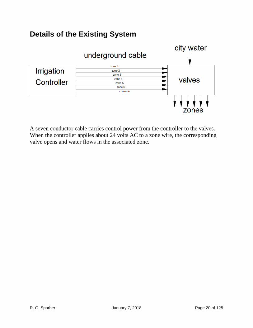
Details of the Existing System
A seven conductor cable carries control power from the controller to the valves.
When the controller applies about 24 volts AC to a zone wire, the corresponding
valve opens and water flows in the associated zone.

R. G. Sparber January 7, 2018 Page 21 of 125
Introduction to the New Functionality
The Flow Measuring Device George depends on knowing the precise flow rate in order to
do his job. Therefore, the first thing I bought was a water
meter. It was on eBay for $27 including shipping. This
meter is a Badger model 25 with a plastic body10
.
By removing a screw (red arrow),
the readout head comes off. This provides access to a
surface with a spinning steel bar under it. The bar turns as
a function of flow through the meter. I see one revolution
every 0.028 gallons of flow11
.
I sense the steel bar with a magnet attached to an arm. The
arm is supported by a ball bearing so is free to spin. A
magnetic sensor suspended over the path of the magnet
reports each revolution. It outputs pulses that are read by
George.
By measuring the flow over 1 minute, George calculates the
Gallons Per Minute (GPM). The meter connects between the
city water inlet and my valves and will provide water usage for
my irrigation system. This is necessary but not sufficient for
knowing the water usage per zone.
Logic is needed to look at which zone is active and how much
water is flowing.
10
The picture is of a bronze body meter. The plastic ones cost less and are black. 11
I used the city's water meter while I counted revolutions to determine this conversion factor.

R. G. Sparber January 7, 2018 Page 22 of 125
The Flow Monitor and Control The second piece of the puzzle is the Flow Monitor and Control
that will read the flow signal from the water meter plus read and
control the signals in the cable. This intelligence will have control
of the valves including overriding the Irrigation Controller if a
fault occurs in the valves or irrigation zones.
The FMC is built using discrete parts plus an Arduino
system on a board. Since this is a prototype, I used a
board much larger than ultimately needed. These
things do have a tendency to grow over time.
If turned into a real product, I expect the electronics to
be all Surface Mount Technology. It likely could be
slightly larger than the display.
Presenting the Design I have no interest boring you with how I arrived at the following design. Instead I
will present the illusion that it was a simple task with no dead ends or false starts.
The hardware will be presented first starting with a high level view and ending
with circuits. Then the software will be presented starting with a high level view
and ending in code.

R. G. Sparber January 7, 2018 Page 23 of 125
Level One System Block Diagram The Flow Monitor and Control
taps into each zone output of the
Irrigation Controller. It also
connects to the Common (COM)
wire. Under non-fault
conditions, "Common out"
(COM out) connects to COM.
All of the valves have two wires. One wire connects to a zone wire. The
other wire is joined with all other valves into a single conductor called
Common. Apply power between any zone wire and Common and that
valves will operate.
The figure shows the flow signal connected to wires in the underground cable. In
my case, the original cable had no spare wires so I had to run another cable.

R. G. Sparber January 7, 2018 Page 24 of 125
Level Two System Block Diagram
The FMC's Human/Machine Interface consists of a display, two buttons, and a
piezoelectric beeper. The beeper can be seen on the left side of the box (red arrow).
On many screens you will see "D[xx" where "xx" is a number between 0 and 70.
This is a countdown timer that tells me how long until the next update. If during
the day, you will see "D". At night, it will be "N". Remember that Minor Alarms
sound only during the day. Major Alarms sound when they occur.
It is also common to see the flow rate on the
second line. Here you have 4.54 GPM. It is
being compared to the reference which is
also 4.54. If there was no reference yet, you
would have seen "ref-". After the zone has
run once, the "-" is replaced by the reference flow.
The top button clears all alarms. If the problem has not been corrected, the alarm
will reappear after 70 seconds. The bottom button will temporarily silence the
audible alarm. A Minor Alarm will stay quiet for 24 hours. A Major Alarm will
return in 15 minutes.
The audible alarms emanate from the piezoelectric beeper. Intentionally, it is
extremely annoying. A Minor Alarm will be on for 0.3 seconds and off for 2

R. G. Sparber January 7, 2018 Page 25 of 125
seconds. A Major Alarm will be on for 0.1 seconds and off for 0.1 seconds. These
patterns were chosen so they would not sound like a smoke alarm.
Flow Monitor and Control Inputs The FMC will monitor all outputs of the Irrigation Controller so it knows what
zone is supposed to be active.
Under automatic control, there
should be only one zone
running at a time.
The FMC will also accept the
common wire. This is the
return path for all valves. If
the FMC detects excessive
flow through a valve, it will be
able to disconnect the
common wire and remove
power to all valves.
The light sensor is located outside and outputs a logic 1 when the sun is out. It tells
the system when there is daylight so safe to sound minor
audible alarms.
This approach lets me avoid the cost and complexity of
including a real time clock. I do not need to know the
exact time, just that it is a reasonable hour to sound a non-
urgent alarm.
The irrigation water meter has a Hall Effect magnetic sensor attached to it. For
every 0.028 gallons of water passed through the meter, the sensor will generate a
pulse on the Flow line (red arrow). The FMC counts these pulses over time to
determine flow rate. The maximum flow I have seen is 15 GPM. This means a
pulse every
.
The software has been designed to keep up with this pulse rate.

R. G. Sparber January 7, 2018 Page 26 of 125
The FMC receives unregulated
12V DC.
It is used directly to run the relay
that switches common and also
to power the piezoelectric
beeper. Most of this power feeds
into a 5V regulator which
supplies the rest of the board.
Flow Monitor and Control Outputs The FMC switches the switched
common line between the
common line at its input and an
open circuit.
The LCD display tell the user
status.
Power is supplied to the magnetic
sensor on the water meter.
The audible alarm is sounded by
the software to alert the user of
any fault conditions.

R. G. Sparber January 7, 2018 Page 27 of 125
Level Three System Block Diagram The FMC is controlled by an
Arduino Pro Micro 5V/16
MHz. In runs on 5V and has
a 16 MHz clock. The
Arduino is paired with a
MCP23017 port expander to
provide sufficient digital
input and output pins.
Starting at the top, we have
unregulated 12V DC coming
from a wall wart. This
power supply can deliver up
to 500 mA. The voltage is
fed to the piezoelectric
beeper and to the relay that
switches the common wire.
A 5V regulator brings the
12V down to a level used by
the rest of the electronics.
Below the 5V regulator are
our signal converters. They
sense 24VAC on the zone
leads and convert them to 5V logic levels.
Next we have the All Zones Off function. It contains a normally closed relay under
software control. When no power is applied to this relay, the "common" wire is
connected to the "switched common" wire. When needed, the Arduino will send an
active AZO signal to the All Zones Off box which will energize the relay and
disconnect the switched common from the common wire. This will cut power to all
valves. Note that if the FMC loses power, it will become transparent to the
RainBird Irrigation Controller.

R. G. Sparber January 7, 2018 Page 28 of 125
The PEST audible alarms and clear alarm buttons feed
directly into the port expander which has been configured to
connect 20K pull up resistors.
The light sensor generates a digital signal compatible with
the port expander. The sensor was placed where it can detect
daylight. If an irrigation fault is detected and controlled, the resulting alarm won't
sound until the sun comes out. No need to wake me.
The flow signal from the irrigation water meter feeds directly into the port
expander.
Software is used to remove any mechanical bounce in the buttons.
The Arduino has three outputs.
During an irrigation fault condition, it drives the AZO
signal which cuts power to all valves and hopefully stops
water flow.
It drives an audible alarm, AA, to notify the user when a
problem has been detected.
And finally, The Arduino feeds the Liquid Crystal Display to provide system
status. While the other three outputs are single pins, the display takes 6.

R. G. Sparber January 7, 2018 Page 29 of 125
Built In Testing Features In order to facilitate testing, a flow simulator has been built
into the software and hardware. The port expander can
output a pulse stream equivalent to a flow of 4.5 GPM. It
can also output 9 GPM and 2.25 GPM. These signals are
used to test nominal, Overflow, and Underflow states. By
moving a jumper I can select the flow sensor or simulated
flow. The jumper is shown in the flow sensor position.
My jumper block is made from a length of connector to
make it easier to grasp around all of those pins.
Not shown in the diagram are two jumpers that can simulate
Zone 1 and Zone 2 being active. Here you see both jumpers
set to normal operation.
An LED with limiting resistor connects across the relay coils. This makes it easier
to see when the software has disconnected the switched common wire from the
common wire.
Additionally, there is a software switch called SpeedUp. When turned on, the
software only measures flow for 10 seconds rather than a full minute. It also
shortens the PEST intervals to 100 seconds. This makes testing the software
quicker.

R. G. Sparber January 7, 2018 Page 30 of 125
Level Four System Block Diagram At this level of detail, each functional block is described.
Flow Sensor Mechanism
I started with a Badger model 25 flow meter. The readout
mechanism was lifted off
and my interface hardware dropped in place.
The interface hardware was an unfortunate addition.
Originally I thought that there was a spinning magnet
inside the water meter. This could be directly sensed
by a Hall Effect device. But upon investigation, I
discovered that a steel bar was in there. The interface
hardware senses the bar and generates a spinning
magnetic field. Then my Hall Effect device can do its
job and convert revolutions to pulses. By using the
City's water meter as my reference, I found that one
revolution equals 0.028 gallons of flow.

R. G. Sparber January 7, 2018 Page 31 of 125
The bar has a spigot on the back
that is a close fit to the ID of a ball
bearing. The bar has a ¼ inch
diameter hole in it that accepts a
neodymium magnet 1/8 inch thick.
I locked it in place with 3 punch
marks. At first I had two magnets
but found that this prevented
movement.
I later found that I needed to move
the bar closer to the top of the
meter in order to insure reliable
coupling. Placing a 3/8 inch
diameter by 1/8 inch thick magnet
on top did the trick.
Looking at the underside of the enclosure, you
can see the ball bearing's inside diameter. The
spigot slides through and is secured with a screw
on the other side.
This hole accepts the Hall Effect sensor.
R. G. Sparber January 7, 2018 Page 32 of 125
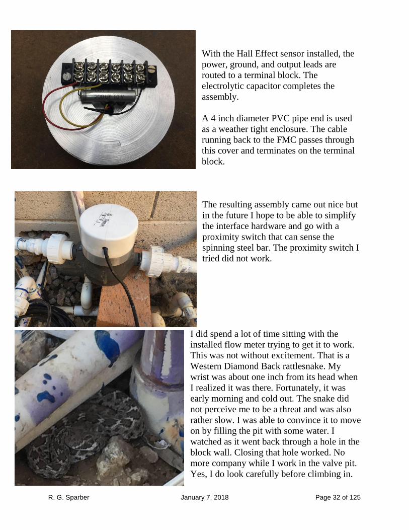
With the Hall Effect sensor installed, the
power, ground, and output leads are
routed to a terminal block. The
electrolytic capacitor completes the
assembly.
A 4 inch diameter PVC pipe end is used
as a weather tight enclosure. The cable
running back to the FMC passes through
this cover and terminates on the terminal
block.
The resulting assembly came out nice but
in the future I hope to be able to simplify
the interface hardware and go with a
proximity switch that can sense the
spinning steel bar. The proximity switch I
tried did not work.
I did spend a lot of time sitting with the
installed flow meter trying to get it to work.
This was not without excitement. That is a
Western Diamond Back rattlesnake. My
wrist was about one inch from its head when
I realized it was there. Fortunately, it was
early morning and cold out. The snake did
not perceive me to be a threat and was also
rather slow. I was able to convince it to move
on by filling the pit with some water. I
watched as it went back through a hole in the
block wall. Closing that hole worked. No
more company while I work in the valve pit.
Yes, I do look carefully before climbing in.

R. G. Sparber January 7, 2018 Page 33 of 125
Flow Monitor and Control Here is an overview of the subsystems on the perf board.
2 row by 16 character LCD
Arduino Pro Mini
Signal Converter Subsystem
Port expander
Relay driver and status LED
5V regulator
Testing jumpers
The relay is mounted on the back side.

R. G. Sparber January 7, 2018 Page 34 of 125
Signal Converter Subsystem
The zone wires will either have about 24V RMS on them or be open circuits. The
signal converter circuit monitors this AC voltage and puts the state in a format
readable by the Arduino.
The signal converter circuit
consists of 2 resistors and 2
NPN transistors. The input is
the voltage Vzone n and the
output is VZn.
When Vzone n is above about
2V, Q1 turns on. This pulls
down on the Zn node and
presents a logic 0 to the port
expander.
While Q1 is on, Q2 has about
-0.65V across its base emitter
junction. This keeps Q2 off but does no damage.
When Vzone n is below about -2V, Q2 turns on. This pulls down on the Zn node and
presents a logic 0 to the port expander.
When Vzone n is less than 0.6V but greater than -0.6V, both transistors will be off.
The output then gets pulled up to Vcc (+5V) by internal pull up resistor R3.
Note the red vertical line on the VZn trace as Vzone n changes from
positive to negative. This results from Vzone n being less than 2V
in magnitude. The spike is treated the same as bounce on a
mechanical switch.
See Appendix 1 on page 67 for details on this narrow pulse which is about 320
microseconds wide.
R. G. Sparber January 7, 2018 Page 35 of 125
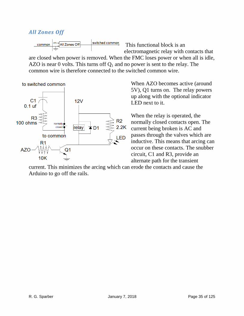
All Zones Off
This functional block is an
electromagnetic relay with contacts that
are closed when power is removed. When the FMC loses power or when all is idle,
AZO is near 0 volts. This turns off Q1 and no power is sent to the relay. The
common wire is therefore connected to the switched common wire.
When AZO becomes active (around
5V), Q1 turns on. The relay powers
up along with the optional indicator
LED next to it.
When the relay is operated, the
normally closed contacts open. The
current being broken is AC and
passes through the valves which are
inductive. This means that arcing can
occur on these contacts. The snubber
circuit, C1 and R3, provide an
alternate path for the transient
current. This minimizes the arcing which can erode the contacts and cause the
Arduino to go off the rails.
R. G. Sparber January 7, 2018 Page 36 of 125
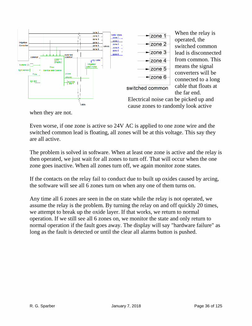
When the relay is
operated, the
switched common
lead is disconnected
from common. This
means the signal
converters will be
connected to a long
cable that floats at
the far end.
Electrical noise can be picked up and
cause zones to randomly look active
when they are not.
Even worse, if one zone is active so 24V AC is applied to one zone wire and the
switched common lead is floating, all zones will be at this voltage. This say they
are all active.
The problem is solved in software. When at least one zone is active and the relay is
then operated, we just wait for all zones to turn off. That will occur when the one
zone goes inactive. When all zones turn off, we again monitor zone states.
If the contacts on the relay fail to conduct due to built up oxides caused by arcing,
the software will see all 6 zones turn on when any one of them turns on.
Any time all 6 zones are seen in the on state while the relay is not operated, we
assume the relay is the problem. By turning the relay on and off quickly 20 times,
we attempt to break up the oxide layer. If that works, we return to normal
operation. If we still see all 6 zones on, we monitor the state and only return to
normal operation if the fault goes away. The display will say "hardware failure" as
long as the fault is detected or until the clear all alarms button is pushed.

R. G. Sparber January 7, 2018 Page 37 of 125
Pushbuttons When either of the pushbuttons is depressed, a contact
closes and the port expander
sees a logic 0. When released,
the internal pull up resistor
generates a logic 1.
This closing action may cause
the contacts to bounce.
Software is used to filter that
out. We take 10 readings and
average the result. If it is less
than ½, we call a zero. Greater than or equal to ½ is a one.

R. G. Sparber January 7, 2018 Page 38 of 125
Light Sensor
I am using an ALS-PT19 light sensor from Adafruit Industries. When light shines
on the sensor, the phototransistor, Q1 conducts. This moves the output voltage
towards the voltage on the positive terminal. Without light, Q1 is off and the
output voltage moves towards the voltage on the negative terminal.
My light sensor is mounted inside a glass bottle that is a tight
fit into a PVC 45° coupler. I happen to have two wire speaker
cable. Since the ALS-PT19 has three terminals, I would need
to run two of these speaker cables and have half of one cable
unused.
Instead, I chose to not use R1. Then I was able to use a single cable between sensor
and Arduino board. Over at the Arduino I duplicated R1 plus put a 5K variable
resistor, R3, from the output signal to ground. It was then possible to adjust the
variable resistor so daytime generated a logic 1 and nighttime produced a logic 0.
This scheme lets me avoid the cost and complexity of having a battery backed up
real time clock.

R. G. Sparber January 7, 2018 Page 39 of 125
Flow Interface The Hall Effect Sensor pulls the Flow lead down to ground very quickly to
generate a logic 0. With a logic 1 it just lets go. Rise time is defined by the
capacitance of the cable12
and a pull up resistor. This means that the fall time is
extremely small compared to the rise time. Both are much smaller than the
minimum period of the pulse stream.
The fast fall time is not a good thing. It causes
undershoot at the port expander that is greater
than what the device can safely handle.
I see about -0.8V which is beyond the -0.5V spec.
By placing a 50 ohm resistor in series with the Hall Effect device's output, I was
able to slow the fall time and therefore reduce undershoot. Now the undershoot is
about -0.2V so all is well. It still takes only about 200 ns to go from +5V down to
near 0.
12
My cable is 50 feet long.
R. G. Sparber January 7, 2018 Page 40 of 125
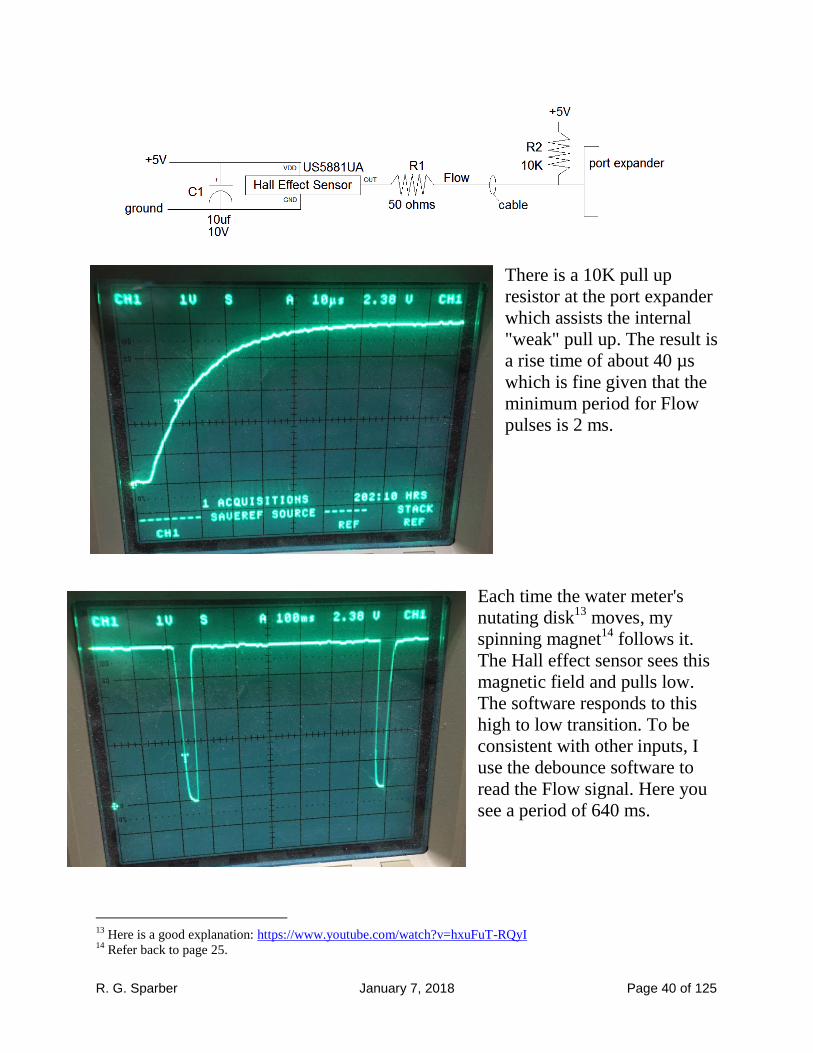
There is a 10K pull up
resistor at the port expander
which assists the internal
"weak" pull up. The result is
a rise time of about 40 µs
which is fine given that the
minimum period for Flow
pulses is 2 ms.
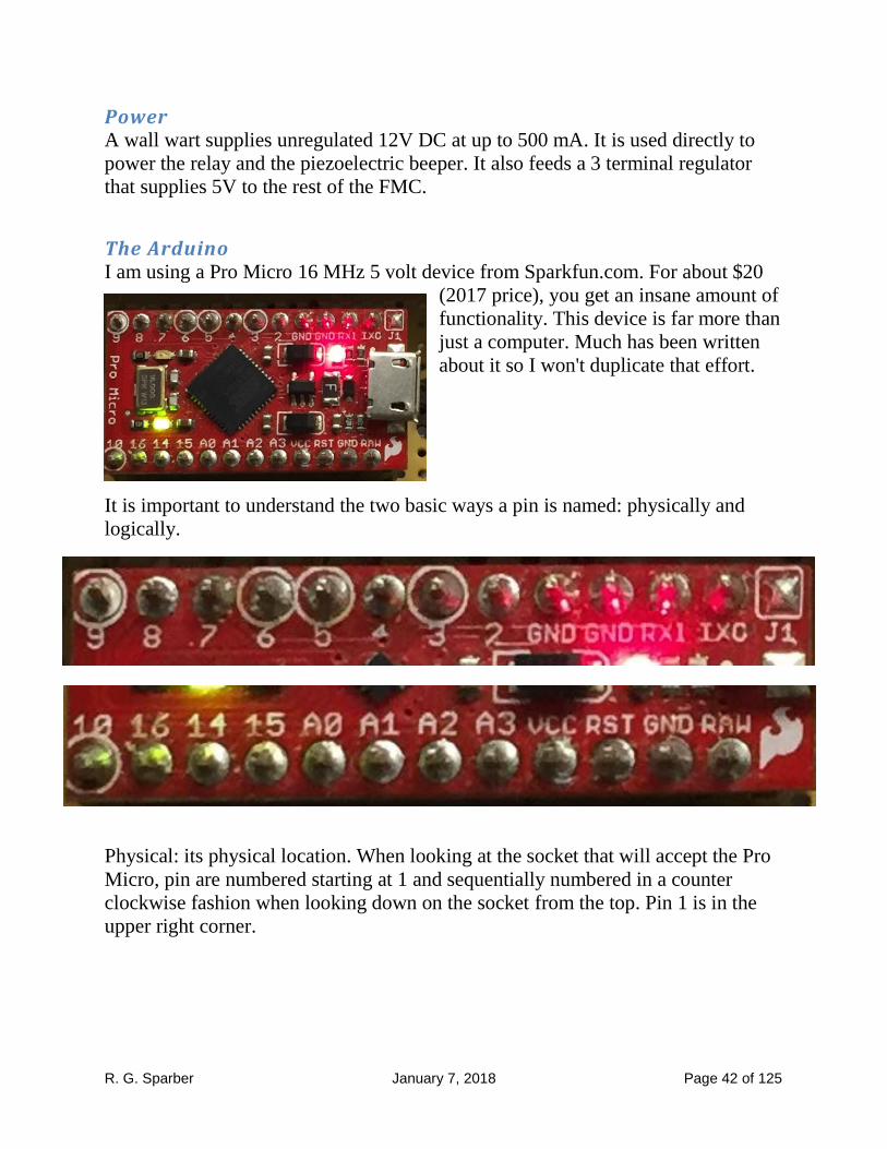
Each time the water meter's
nutating disk13
moves, my
spinning magnet14
follows it.
The Hall effect sensor sees this
magnetic field and pulls low.
The software responds to this
high to low transition. To be
consistent with other inputs, I
use the debounce software to
read the Flow signal. Here you
see a period of 640 ms.
13
Here is a good explanation: https://www.youtube.com/watch?v=hxuFuT-RQyI 14
Refer back to page 25.

R. G. Sparber January 7, 2018 Page 41 of 125
Give a period of 640 ms we can verify the conversion process works. Each pulse
represents 0.028 gallons. Therefore
The display showed 2.69 GPM which is a difference of 0.03 GPM or 1 pulse. All
readings are ±1 pulse so this is reasonable.
The maximum flow rate that I have directly measured is around 15 GPM. The
software can handle up to 63 GPM.
R. G. Sparber January 7, 2018 Page 42 of 125
Power A wall wart supplies unregulated 12V DC at up to 500 mA. It is used directly to
power the relay and the piezoelectric beeper. It also feeds a 3 terminal regulator
that supplies 5V to the rest of the FMC.
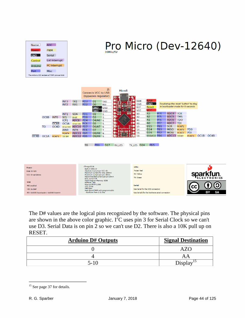
The Arduino I am using a Pro Micro 16 MHz 5 volt device from Sparkfun.com. For about $20
(2017 price), you get an insane amount of
functionality. This device is far more than
just a computer. Much has been written
about it so I won't duplicate that effort.
It is important to understand the two basic ways a pin is named: physically and
logically.
Physical: its physical location. When looking at the socket that will accept the Pro
Micro, pin are numbered starting at 1 and sequentially numbered in a counter
clockwise fashion when looking down on the socket from the top. Pin 1 is in the
upper right corner.

R. G. Sparber January 7, 2018 Page 43 of 125
Logical: the logical names of the pins. Some of these names are letters, some are
numbers, and the rest are a mix of letters and numbers. For example, physical pin 1
has the logical name TXO. It can get rather confusing at times. Consider physical
pin 5 which is logical pin 2. On top of this, you can configure each of these logical
pins to be any one of
a number of types.
This further changes
the name. For
example, logical pin
2 can be configured to
be a Serial Data port
(SDA) or to be
Interrupt 1 (INT1).
You really need a score card to keep it all straight! Fortunately, Sparkfun has done
a masterful job of providing such a card as can be seen on the next page.
R. G. Sparber January 7, 2018 Page 44 of 125
The D# values are the logical pins recognized by the software. The physical pins
are shown in the above color graphic. I2C uses pin 3 for Serial Clock so we can't
use D3. Serial Data is on pin 2 so we can't use D2. There is also a 10K pull up on
RESET.
15
See page 37 for details.
Arduino D# Outputs Signal Destination
0 AZO
4 AA
5-10 Display15

R. G. Sparber January 7, 2018 Page 45 of 125
One limitation of the Pro Micro is the number of input/output pins. This is easily
solved by adding a MCP23017 Port Expander. The device is controlled via I2C
using the Serial CLock and Serial DAta pins.
Connect pin #12 (SCL) of the expander to the Arduino SCL pin plus add a 1K
pull-up resistor to 5V.
Connect pin #13 (SDA) of the expander to Arduino SDA pin plus add a 1K pull-up
resistor to 5V.
Connect pins #15, 16 and 17 of the expander to ground (address selection).
Connect pin #9 (VDD) of the expander to 5V.
Connect pin #10 (Vss) of the expander to ground.
Connect pin #18 (RESET) through a 10K ohm resistor to 5V (reset pin, active
low).
From Adafruit: https://cdn-shop.adafruit.com/datasheets/mcp23017.pdf
GPA0-7 and GPB0-7 give a total of 16 input/output pins.
An example of how to use this device can be found at
https://github.com/adafruit/Adafruit-MCP23017-Arduino-
Library/blob/master/examples/button/button.ino#L1

R. G. Sparber January 7, 2018 Page 46 of 125
We must include two header files
available from Adafruit: wire.h and
Adafruit_MCP23017.h. The file
"wires.h" sets up the I2C interface.
Port Expander Input
Name
Virtual
pin#
Physical pin
#
Signal
Source
GPA0 0 21 Zone 1
GPA1 1 22 Zone 2
GPA2 2 23 Zone 3
GPA3 3 24 Zone 4
GPA4 4 25 Zone 5
GPA5 5 26 Zone 6
GPA6 6 27 PAB
GPA7 7 28 CAB
GPB0 8 1 LS
GPB1 9 2 Flow
This leaves 6 spare virtual I/O pins (10 - 15) on the port expander. I use three of
them as outputs of a flow simulator:
Port Expander Input
Name
Virtual
pin#
Physical
pin #
Description
GPB2 10 3 Half of nominal
GPB3 11 4 nominal
GPB4 12 5 Twice nominal
This flow simulator will generate a square wave of 50% duty cycle and output the
above 3 signals as long as the program is running. The cycle rate of the loop is
divided by the FlowSimulatorDivider value. Additionally, jumpers exist that can
pull Zone 1's and/or Zone 2's input to ground to simulate it/them going active.
R. G. Sparber January 7, 2018 Page 47 of 125
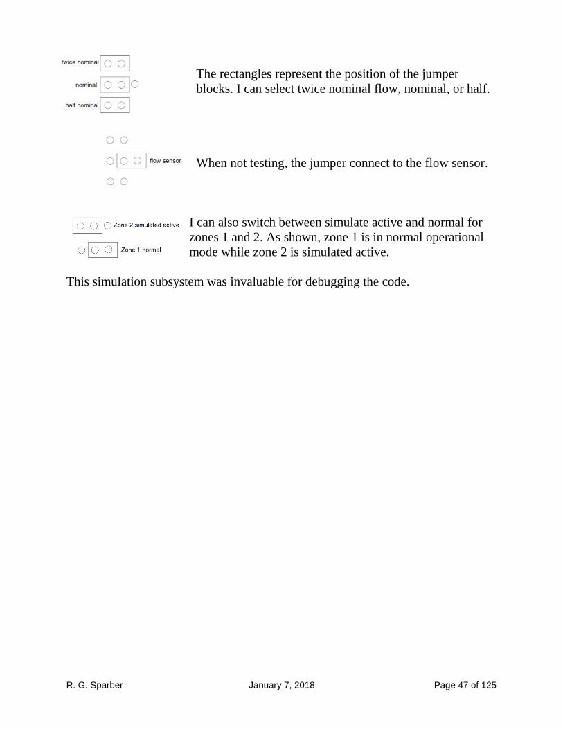
The rectangles represent the position of the jumper
blocks. I can select twice nominal flow, nominal, or half.
When not testing, the jumper connect to the flow sensor.
I can also switch between simulate active and normal for
zones 1 and 2. As shown, zone 1 is in normal operational
mode while zone 2 is simulated active.
This simulation subsystem was invaluable for debugging the code.
R. G. Sparber January 7, 2018 Page 48 of 125
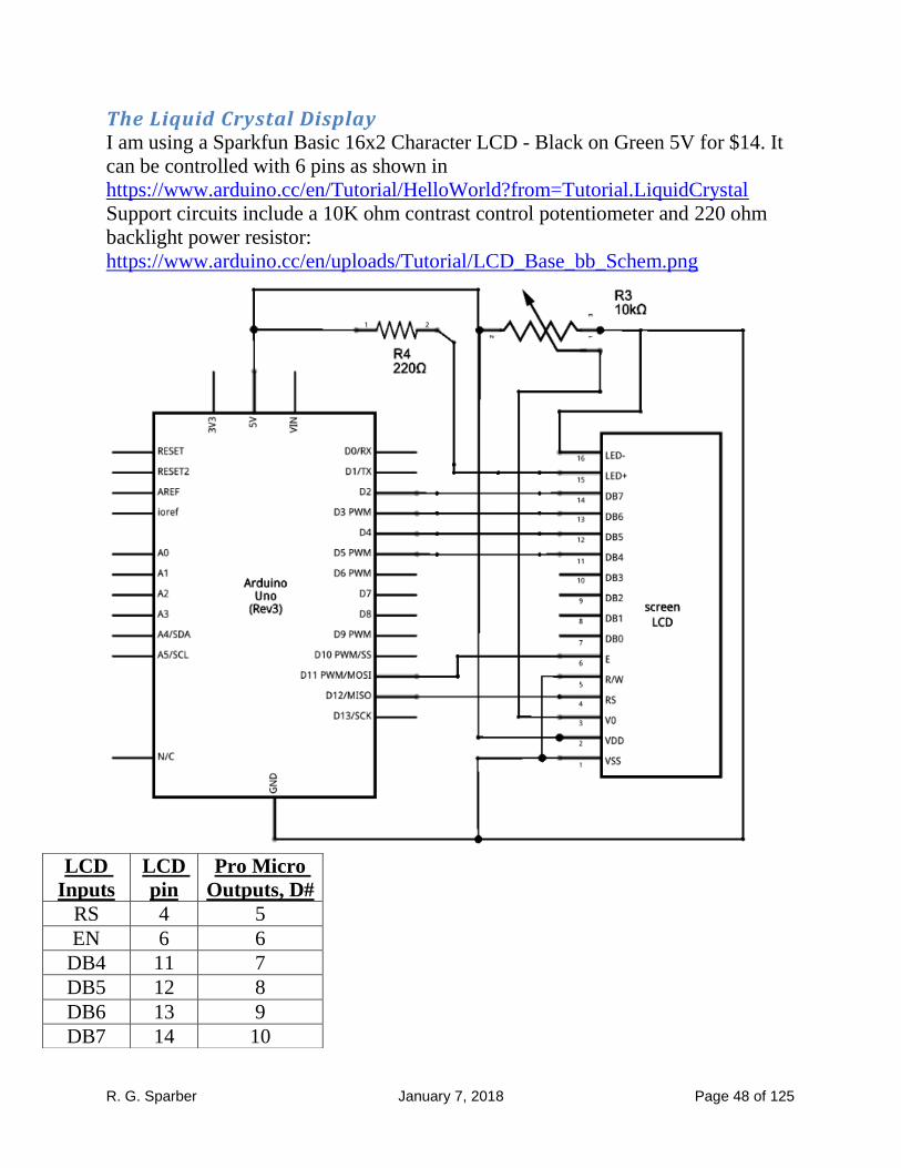
The Liquid Crystal Display I am using a Sparkfun Basic 16x2 Character LCD - Black on Green 5V for $14. It
can be controlled with 6 pins as shown in
https://www.arduino.cc/en/Tutorial/HelloWorld?from=Tutorial.LiquidCrystal
Support circuits include a 10K ohm contrast control potentiometer and 220 ohm
backlight power resistor:
https://www.arduino.cc/en/uploads/Tutorial/LCD_Base_bb_Schem.png
LCD
Inputs
LCD
pin
Pro Micro
Outputs, D#
RS 4 5
EN 6 6
DB4 11 7
DB5 12 8
DB6 13 9
DB7 14 10
R. G. Sparber January 7, 2018 Page 49 of 125
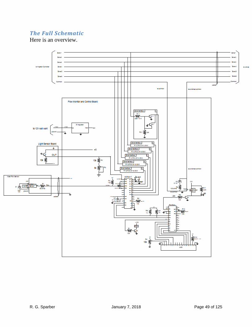
The Full Schematic Here is an overview.

R. G. Sparber January 7, 2018 Page 50 of 125
The zone wires from the Irrigation Controller pass through but are monitored. The
Common wire goes into the FMC and back out. All of these wires go into Cable 1
that runs out to the zone valves.
Power from the wall wart feeds the 5 volt regulator along with the relay and
piezoelectric beeper, not shown here.
The Light Senor runs through a two conductor cable a short distance to where it
can see daylight.
The six zone interface circuits are identical. Note that zone interface 1 shows all
detail and the rest are identical except for the names of the components. When 24
VAC is seen on a zone line, the interface sends a logic 0 to the port expander.

R. G. Sparber January 7, 2018 Page 51 of 125
The port expander, MCP23017, outputs test flow signals that are selectable via
optional jumpers. It accepts inputs from the clear all alarms and PEST audible
alarms buttons.
The Pro Micro Arduino controls the port expander via the I2C which consists of the
Serial Data (SDA) and Serial Clock (SCL) lines. It drives the piezoelectric beeper
via R1 and Q3 plus the relay via R9 and Q4. And finally, it drives the Liquid
Crystal Display.

R. G. Sparber January 7, 2018 Page 52 of 125
Bill Of Materials Estimated cost is $80 plus the cost of the Badger flow meter, cable, and enclosure.
Name Quantity Description Notes
R1 1 50 ohms 1/8W Mouser.com
R1.1 - R1.6 6 5.6K 1/4W Mouser.com
R2.1 - R2.6 6 1.5K 1/8W Mouser.com
R3 1 10K 1/8W pot Mouser.com
R4, R5, R9, R10, R12 5 10K 1/8W Mouser.com
R6, R7 2 1K 1/8W Mouser.com
R13 1 220 ohms Mouser.com
R8 1 100 ohms 1/4W Mouser.com
R11 1 2.2K 1/8W Optional
R14 1 5K 1/8W pot Mouser.com
C1 1 10 uf 10V electrolytic Mouser.com
C2, C3 2 0.1 uf Mouser.com
Q1.1 - Q1.6, Q2.1 - Q2.6, Q3, Q4 14 BC550B or any general purpose
NPN
Mouser.com
D1 1 any general purpose diode Mouser.com
LED 1 any general purpose LED optional
RELAY 1 OUAZ-SS112D,900 Mouser.com
LIGHT SENSOR 1 ALS-PT19 Adafruit.com
HALL EFFECT DEVICE 1 US5881UA Mouser.com
PRO MICRO 1 Arduino Sparkfun.com
PORT EXPANDER 1 MCP23017 Adafruit.com
PIEZO 1 254-20C6-ROX Mouser.com
LCD 1 LCD 00709 Sparkfun.com
PUSH BUTTON 1 AND 2 2 any general purpose low power
PERFERATED CIRCUIT BOARD 2 As needed
CABLE 1, CABLE 2 As needed
FLOW METER 1 BADGER MODEL 25 eBay.com
FLOW SENSOR ENCLOSURE 1 See page 30
FLOW MONITOR AND
CONTROL ENCLOSURE
1 Your choice
5V Regulator 1 833-MC7805CT-BP Mouser.com
12VDC at 500 mA unregulated
power supply
1 Your choice
jumper 3 Two terminal blocks optional

R. G. Sparber January 7, 2018 Page 53 of 125
Software We have 6 zones. Normally no
more than one zone is on at a
time. Any zone can have a flow
that is too low or too high.
Depending on the fault, we
might be able to stop excessive
flow. At any time there can be a
change in active zone or in fault
state.
The result is similar to a pinball machine with many possible
states. For example, zone 1 might be running normally while
zone 4 is in underflow and zone 5 is in overflow but
controlled. The software must deal with all of these
situations. Appendix 5 contains a list of my test cases. All of
these cases passed but that does not mean the software is free
of bugs.
R. G. Sparber January 7, 2018 Page 54 of 125
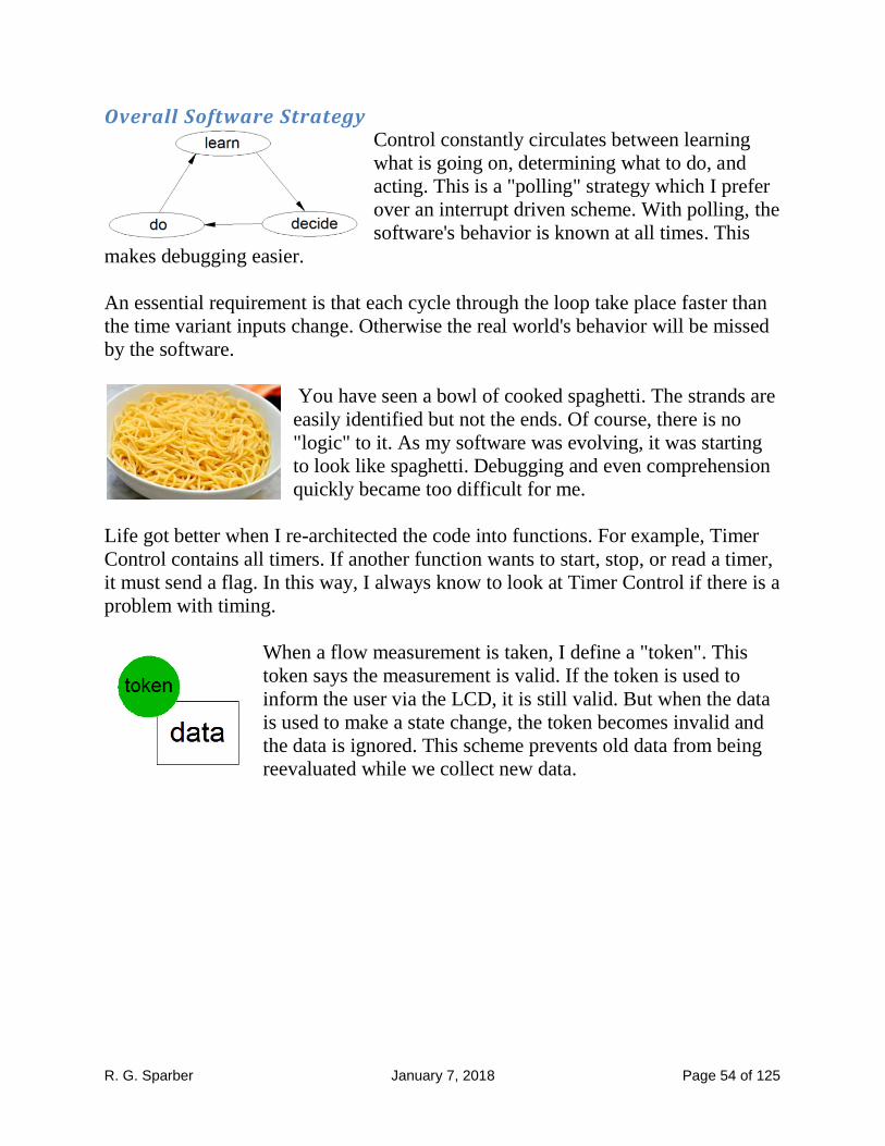
Overall Software Strategy Control constantly circulates between learning
what is going on, determining what to do, and
acting. This is a "polling" strategy which I prefer
over an interrupt driven scheme. With polling, the
software's behavior is known at all times. This
makes debugging easier.
An essential requirement is that each cycle through the loop take place faster than
the time variant inputs change. Otherwise the real world's behavior will be missed
by the software.
You have seen a bowl of cooked spaghetti. The strands are
easily identified but not the ends. Of course, there is no
"logic" to it. As my software was evolving, it was starting
to look like spaghetti. Debugging and even comprehension
quickly became too difficult for me.
Life got better when I re-architected the code into functions. For example, Timer
Control contains all timers. If another function wants to start, stop, or read a timer,
it must send a flag. In this way, I always know to look at Timer Control if there is a
problem with timing.
When a flow measurement is taken, I define a "token". This
token says the measurement is valid. If the token is used to
inform the user via the LCD, it is still valid. But when the data
is used to make a state change, the token becomes invalid and
the data is ignored. This scheme prevents old data from being
reevaluated while we collect new data.

R. G. Sparber January 7, 2018 Page 55 of 125
Many timers are used. In some cases I just need to know that a given timer is
running. In other cases I need to know when it starts and when it ends. Flags are
defined in the Timer Control subroutine and used by the rest of the code.
If you make it all the way down to the code, you will see that I have taken full
advantage of variables and subroutine naming freedom. These tags have been
selected to help me remember what is going on. For example, The subroutine used
to get zones states is called GetZoneStates( ). My flag that tells me I just set the
inhibit flag active is called JustSetInhibitActive. These long names are removed
during compilation so do not take up space in the Arduino's memory. By using
copy and paste, I avoid typing them more than once.

R. G. Sparber January 7, 2018 Page 56 of 125
Level 1 Flowchart When viewed for the first time, I'm sure there is an urge to just turn the page. If
you just want to run the code, there is no need to go further. But if you want to
understand the code, here is the first step.

R. G. Sparber January 7, 2018 Page 57 of 125
When the program starts for the first time, it has no
flow data on each zone. After it has run each zone, that
data exists.
Starting at "No zones
active",
we go to "zone n active".
The flow is measured for
60 seconds. When done, we
see if the zone's valve was
closed due to a previous
fault. If it was not, we see if
this zone has ever run
before. If this is the first
time, we have no historical
flow data so cannot judge if
there is a problem. If it has
run before, we know what
"nominal16
" means so start
judging the flow. If the
flow is below 70% of
nominal, we have
Underflow and set Minor
Alarm for this zone. Then
we start the cycle over.
If Above nominal by more
than 30%, we close the
valve every time this zone
is active. Then we start the cycle over.
If the flow is within 30% of nominal, it is ok and we start the cycle over.
16
"nominal" uses too many characters on my LCD so I use "ref" there.

R. G. Sparber January 7, 2018 Page 58 of 125
If the valve has been closed
when this zone is active, we
check if it was just closed. If
it was, we say the zone is in
Overflow and then see if the
flow is below the leakage
limit.
If closing the valve did not
turn off the flow, we go to
Major Alarm and wait for
human intervention. We
have an uncontrolled flow.
If closing the valve turned
off the flow, we call out a
Minor Alarm for this zone.
As we repeat the cycle, this
zone is defined as in
Overflow with Minor Alarm.
On the next pass, we again
measure the flow and see
that the valve has been
closed. But now we see that
the valve has not just been closed. If the flow is still less than Leakage, the cycle
repeats. If the flow is now greater than Leakage, we retire the Minor Alarm and
escalate to a Major Alarm and wait for help to arrive.
If a zone is in Overflow Minor alarm, every time it runs the FMC blocks the flow.
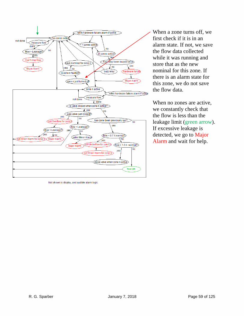
R. G. Sparber January 7, 2018 Page 59 of 125
When a zone turns off, we
first check if it is in an
alarm state. If not, we save
the flow data collected
while it was running and
store that as the new
nominal for this zone. If
there is an alarm state for
this zone, we do not save
the flow data.
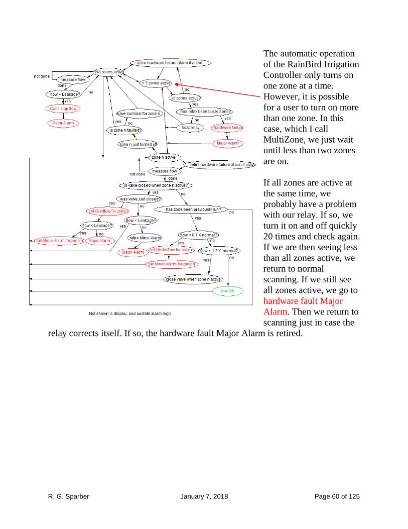
When no zones are active,
we constantly check that
the flow is less than the
leakage limit (green arrow).
If excessive leakage is
detected, we go to Major
Alarm and wait for help.
R. G. Sparber January 7, 2018 Page 60 of 125
The automatic operation
of the RainBird Irrigation
Controller only turns on
one zone at a time.
However, it is possible
for a user to turn on more
than one zone. In this
case, which I call
MultiZone, we just wait
until less than two zones
are on.
If all zones are active at
the same time, we
probably have a problem
with our relay. If so, we
turn it on and off quickly
20 times and check again.
If we are then seeing less
than all zones active, we
return to normal
scanning. If we still see
all zones active, we go to
hardware fault Major
Alarm. Then we return to
scanning just in case the
relay corrects itself. If so, the hardware fault Major Alarm is retired.
R. G. Sparber January 7, 2018 Page 61 of 125
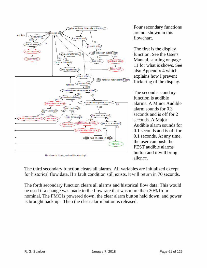
Four secondary functions
are not shown in this
flowchart.
The first is the display
function. See the User's
Manual, starting on page
11 for what is shows. See
also Appendix 4 which
explains how I prevent
flickering of the display.
The second secondary
function is audible
alarms. A Minor Audible
alarm sounds for 0.3
seconds and is off for 2
seconds. A Major
Audible alarm sounds for
0.1 seconds and is off for
0.1 seconds. At any time,
the user can push the
PEST audible alarms
button and it will bring
silence.
The third secondary function clears all alarms. All variables are initialized except
for historical flow data. If a fault condition still exists, it will return in 70 seconds.
The forth secondary function clears all alarms and historical flow data. This would
be used if a change was made to the flow rate that was more than 30% from
nominal. The FMC is powered down, the clear alarm button held down, and power
is brought back up. Then the clear alarm button is released.

R. G. Sparber January 7, 2018 Page 62 of 125
Major Subroutines Here you see the main subroutines that are in the loop and the subroutines called
from them. GetZoneStates()
InitializeZone()
PopulateZones()
FindActiveZone()
ZonePower()
TimerControl()
TransientTimeElapseTimer ()
OneMinuteElapseTimer ()
MinorPestElapseTimer ()
MajorPestElapseTimer ()
MinorCadence()
MajorCadence()
AntiFlickerCadence()
ZoneTransitionQ()
SaveOldZoneFlowMeasurement()
PrepareForNewZone()
ProcessFlowInfo()
GetFlowRate()
DisplayFlowRate()
SuspectRelay
MoreThanOne()
PossibleFault()
NoZoneOnAndNoDataYet()
NoZoneOnWithData()
ActiveZoneNoDataYet()
ZoneActive()
JudgeFlowRate()
MajorAlarm
MultiZoneQ
NoFlowDataQ()
NoHistoryQ()
SmallFlowQ()
UnderflowQ()
OverflowBeforeInhibitQ()
ImmediatelyAfterInhibitFaultQ()
AfterInhibitStableFaultQ()
LeakageNoZonesActiveQ()
RelayErrorControl()
AlarmControl()
CleanUpPrematureAlarmExitQ()
DisplayFaultDetails()
RelayErrorQ()
CABpressed()
SoftwareError()
CannotStop()
Trying()
HaveMinor()
ManuallyClearAlarmQ()
PestActiveAlarmQ()
AudibleAlarmProcessing()
R. G. Sparber January 7, 2018 Page 63 of 125
GetZoneStates() looks at all of the zones and reports back which ones are active.
To do this it calls three subroutines:
InitializeZone()
PopulateZones()
FindActiveZone()
ZonePower() turns the relay on and off under the control of an array of Inhibit
flags. If the Inhibit flag for the active zone is true, then the relay is powered up and
power is removed from this zone's valve.
TimerControl() handles all timers including the transient timer, the one minute
timer, PEST timers, and audible alarm cadence timers. Timers that only run when
needed are initiated by telling them to start. When they start, the clear the start flag
and raise a running flag. When timed out, the running flag is lowered.
ZoneTransitionQ() looks at the previous active zone and the current active zone to
see if there has been a zone transition. If so, it looks to see if the previous active
zone had a fault. If not, it saves the flow data as the new historical flow. If there
was a fault, it does not save the flow data. Then it prepares for the new zone being
active.
ProcessFlowInfo() performs three major tasks. First it measures the flow rate, then
it displays the flow rate, and finally, it judges the flow rate to see if it is normal or
faulted. The subroutine SmallFlowQ() checks the historical flow for the active
zone in order to prevent a division by 0.
RelayErrorControl() displays a message if the relay is stuck.
AlarmControl() handles all alarms associated with flow. This includes displaying
fault details, responding to a manual clear alarms request, responding to a PEST
audible alarm request, and controlling the audible alarm.
R. G. Sparber January 7, 2018 Page 64 of 125
Software Structure Although it is possible to have multiple files that together hold the Arduino
software, I have chosen to put it all in one file to minimize confusion and error.
Separate files must be loaded is a specific order to link correctly.
The following is an outline of how I ordered the segments of the program. Note
that variables and constants defined outside of functions are accessible by all
functions which is why you see so much going on before we reach Setup. See
Appendix 6 on page 75 for the code.
Program name and version number - they are displayed at start up on the LCD
#include - pulls in libraries that define hardware. In my case I have EEPROM,
an LCD display, and a port expander chip that uses I2C.
Constants and variables
MCP23017 port expander inputs
Arduino Outputs
States of the hardware and software
Timers
Rate of change of flow parameters
Flow level parameters
Input states like "Day" versus night and a button being pushed or not
Faults that are recorded and processed
Software error descriptions
LCD flicker reduction parameters
Diagnostic and built in simulator parameters
Hardware Initialization - port expander and LCD
Void Setup - this is where code is placed that only executes once. All of the
input and output pins in the hardware are defined here. We also look at the
pushbuttons to determine if the user wants all historical data erased or if they
want flow measuring mode enabled

R. G. Sparber January 7, 2018 Page 65 of 125
Void Loop - a collection of high level subroutines that hold the major
functional blocks resides here. These subroutines are made up of lower level
subroutines defined next.
Lower level subroutines - these are built from subroutines that are at the lowest
level.
Lowest level subroutines - narrowly defined functions that act as my custom
made program language.
End of file
An important fine point:
Looking at the code, you may spot something odd in my print commands to the
LCD. The standard command would be
lcd.print ("All alarms");
but I wrote
lcd.print (F("All alarms"));
You are looking at the F() subroutine which I found on an Adafruit forum17
. F()
tells the Arduino compiler to keep the string "All alarms" in program store rather
than duplicating it in Static Random Access Memory (SRAM). Without this
subroutine, the program runs out of memory used to store variables and strange
things happen.
For example, I was checking a small block of code because it did not seem to
execute correctly. A series of Serial.println statements told me what was going on.
I could see command 1 being reached followed by command 2. But rather than
command 3 I saw that a subroutine was called. That code did not call this
subroutine. It was corrupted memory caused by the SRAM being corrupted.
17
First try the URL: https://learn.adafruit.com/memories-of-an-arduino/optimizing-sram but if this link is broken,
search using " Adafruit managing sram F()"

R. G. Sparber January 7, 2018 Page 66 of 125
Acknowledgements Very special thanks go to my wife, Donna, for putting up with me constantly at my
computer writing and debugging the software.
I welcome your comments and questions.
If you wish to be contacted each time I publish an article, email me with just
"Article Alias" in the subject line.
Rick Sparber
Rick.Sparber.org
R. G. Sparber January 7, 2018 Page 67 of 125
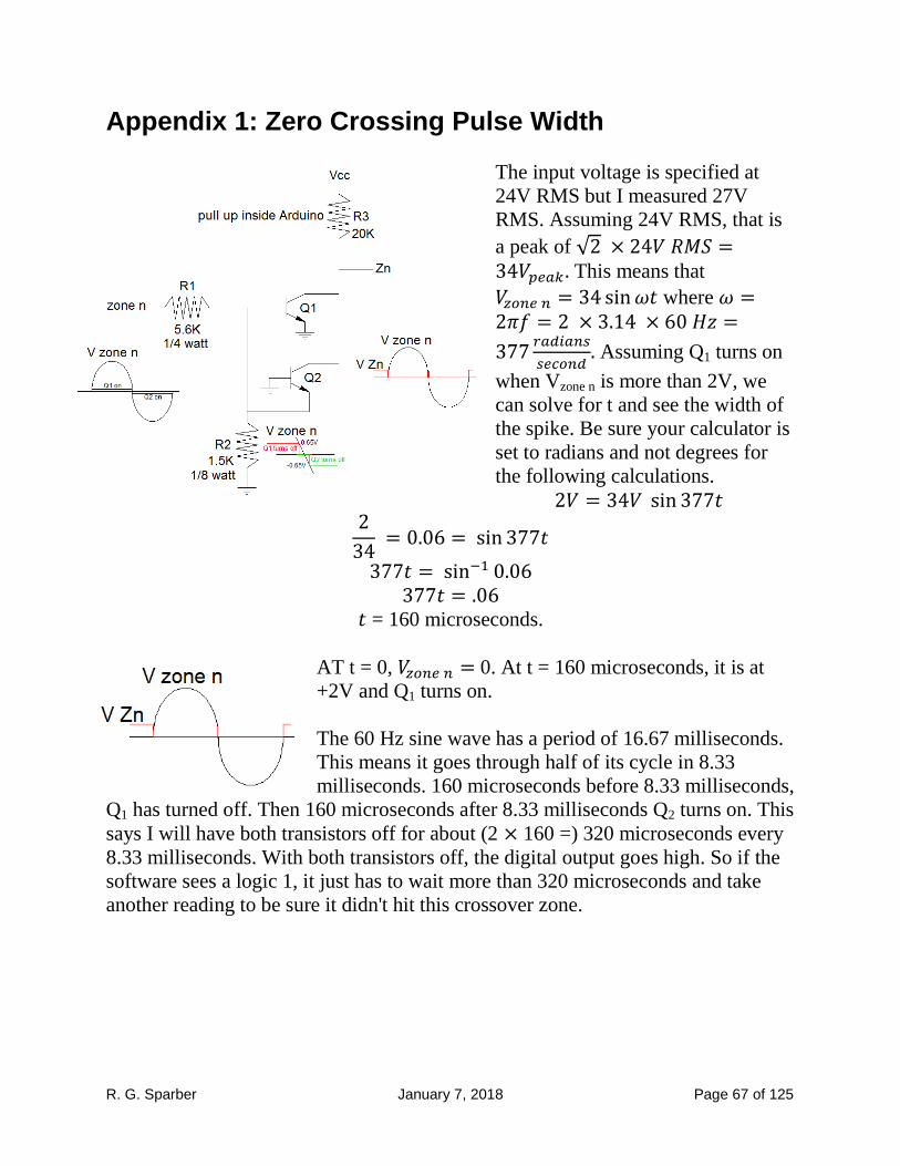
Appendix 1: Zero Crossing Pulse Width
The input voltage is specified at
24V RMS but I measured 27V
RMS. Assuming 24V RMS, that is
a peak of This means that
where
Assuming Q1 turns on
when Vzone n is more than 2V, we
can solve for t and see the width of
the spike. Be sure your calculator is
set to radians and not degrees for
the following calculations.
= 160 microseconds.
AT t = 0, 0. At t = 160 microseconds, it is at
+2V and Q1 turns on.
The 60 Hz sine wave has a period of 16.67 milliseconds.
This means it goes through half of its cycle in 8.33
milliseconds. 160 microseconds before 8.33 milliseconds,
Q1 has turned off. Then 160 microseconds after 8.33 milliseconds Q2 turns on. This
says I will have both transistors off for about (2 160 =) 320 microseconds every
8.33 milliseconds. With both transistors off, the digital output goes high. So if the
software sees a logic 1, it just has to wait more than 320 microseconds and take
another reading to be sure it didn't hit this crossover zone.

R. G. Sparber January 7, 2018 Page 68 of 125
Appendix 2: EEPROM Map The Electrically Erasable Programmable Read-Only Memory (EEPROM) present
inside the Arduino device will hold two seven member arrays of data.
The first array is ZoneNeverRun. It is initialized to all elements true. As each zone
is run for the first time and historical flow data collected, that element will be set to
false. Each element is defined as boolean so takes one byte.
We have:
ZoneNeverRun[i] with i equal any integer from 0 to 6. It occupies EEPROM at
memory locations 0 through 6.
To write to this array, we will use the subroutine WriteZoneNeverRun( ). To read
this array, we will use the subroutine ReadZoneNeverRun( ).
The second array is HistoricalFlow[i]. It is not initialized. Instead, we only look at
a given element when ZoneNeverRun[i] says HistoricalFlow[i] has valid data. As
each zone is successfully run, the measured data is written into this array. Each
element is defined as float so takes four bytes.
We have:
HistoricalFlow[i] with i equal any integer from 0 to 6. It will occupy EEPROM at
memory locations 7 through 28.
To write to this array, we will use the subroutine WriteHistoricalFlow( ). To read
this array, we will use the subroutine ReadHistoricalFlow( ).

R. G. Sparber January 7, 2018 Page 69 of 125
Appendix 3: Arduino Compilation Error Experiences
It has been a while since I programmed an Arduino so ran into many "newbie"
problems. The most confusing were the error messages when my code was not in
the sketch book folder. I saw many errors due to files I just included and even one I
didn't include. They went away once I moved my code to the sketch book folder.
After working through way too many typos in my program, I ran into two
compilation errors related to code supplied by Sparkfun and Adafruit.
The first error was
"main.cpp:43 undefined reference to 'setup'
Collect2.exe: error: ld returned
1 exit status
A search of the web turned up others with this problem plus a solution that worked
for them. Going to the file main.cpp line 43 I found
setup( );
I was instructed to add "void"
void setup( );
After switching to Administrator mode, I was able to save the change.
The second error was
EEPROM.h:43:30: warning: type qualifiers ignored on function return type [-
Wignored-qualifiers]
operator const uint8_t( ) const { return **this; }
I learned that EEPROM.h had two bugs in it. On line 43 was
operator const uint8_t( )
The expert said to remove "const".

R. G. Sparber January 7, 2018 Page 70 of 125
I then was instructed to go to line 92
operator const int( ) const
and remove the first "const". The modified file was then saved. The compilation
was then error free.
R. G. Sparber January 7, 2018 Page 71 of 125
Appendix 4: Anti-flicker
The software is constantly running in a loop. If a given LCD screen is written, it
will be re-written on each pass. This is both bad and good. It is bad because doing
many updates each second causes the LCD to flicker annoyingly. However, it is
good because any corruption of the LCD's displayed data is quickly corrected. The
trick is to do updates often, but not too often. I have found that an LCD refresh
every 10 seconds is about right.
The strategy I chose was to maintain a unique name for each LCD screen plus have
a global flag that presents the opportunity to do an update only every 10 seconds.
This flag is part of the TimerControl() subroutine.
We have two types of LCD screens. The simpler one is just text. I can describe it
with a constant. For example:
const int TryingToClose = 25;
TryingToClose has been assigned an arbitrary but unique value of 25.
I also have screens that display text that doesn't change mixed with numbers that
do change. In these cases, I assign them an arbitrary but unique value that has the
changing number added to it. For example, NoZoneOnWithGPMConstant is
assigned a unique number to represent the No Zone On screen. I generate the
complete screen name by adding the displayed GPM with the result saved as
NoZoneOnWithGPMC.
I keep track of the current LCD screen with the variable lcdNowDisplaying.
When the software is about to print a screen, it checks if the new screen differs
from the old screen or if it is time for an update. If either is true, the LCD screen is
refreshed. The one exception is when the software has closed the valve and is
waiting to see if the flow is now near 0. While displaying the "Trying to close
valve" screen, I block all non-alarm screens. Otherwise, I would get alternating
screens which is unreadable.

R. G. Sparber January 7, 2018 Page 72 of 125
Appendix 5: Test Cases The following Cases are designed to fully test the software so are detailed. There
were developed in parallel with creating the flow charts and thinking about how
my irrigation runs and fails.
"Start" means all variables have been initialized. This is done by powering off,
holding down the clear alarms button, powering on, and then releasing the button.
When a zone is first turned on, the software waits 10 seconds for the flow to
stabilize. It then takes 60 seconds to measure the flow. I am using the built in flow
simulator which generates half nominal, nominal, and twice nominal flow rates.
In all cases, m does not equal n.
Non-fault Cases 1. Start to no zones on for 65 seconds. 2. Start to zone n on 3. Zone n on with nominal flow. Zone n off. Zone n on with nominal flow. See
that nominal flow becomes reference. Turn off power. Hold down Clear all
alarms button. Power up. See that historical data removed. Zone n on with
nominal flow and see that ref is - . 4. Zone n on. Nominal flow for 1.5 minutes. Zone n off. Zone m on.
Nominal flow for 1.5 minutes. Zone m off. Zone n on for 75 seconds. Zone n off. Zone m on for 75 seconds. Zone m off.
5. MultiZone (more than one zone on) a. Before Start have zones n and m on. Start. b. Zone n on. Zone m on. Zone m off. c. Zone n on. Zone m on. Zone n off.
6. No zones on to more than one zone on 7. No zones on to zone n on for first time with nominal flow. See that ref is - . 8. No zones on to zone n on not first time. See that ref has nominal after it.
R. G. Sparber January 7, 2018 Page 73 of 125
Fault Cases A. Single fault
1. No zones on and then flow > leakage so go to "Can't stop flow." Major.
Press Clear All Alarms. 2. Zone n on with underflow. Then pest. 3. Zone n on with underflow. Zone m on normal flow. 4. overflow
a. Zone n on with overflow minor .Then pest. Zone n off. Zone n. b. Zone n on with overflow minor .Then pest. Zone m on with
nominal flow for 75 seconds. Zone m off. Zone n on. c. Zone n on with overflow major. Then pest. Zone m on. Zone m
off. B. Sequential Double fault on same zone
a. underflow 1. Zone n on with underflow. Then pest. Then overflow minor and
should hear minor audible alarm. Then pest. Then clear all alarms. 2. Zone n on with underflow. Hear minor. Then pest. Then overflow
major. Hear major audible alarm. Then pest. Then clear all alarms. 3. Zone n in underflow. Hear minor. Then pest. Then zone n off; zone
m runs normally. 4. Zone n in underflow. Hear minor. Then pest. Then zone n off; zone
m goes into underflow. Hear minor. Then pest. b. Zone n on with overflow minor. Hear Minor audible alarm. Then pest.
Then overflow major. Hear major audible alarm. Then pest. C. First zone faults and then turns off. Second zone on and faults.
1. Underflow a. Zone n in underflow and then zone n off; zone m goes into
overflow minor b. Zone n in underflow and then zone n off; zone m goes into
overflow major 2. Overflow
a. Zone n in overflow minor and then zone n off; zone m runs
normally b. Zone n in overflow minor and then zone n off; zone m goes into
underflow c. Zone n in overflow minor and then zone n off; zone m goes into
overflow minor d. Zone n in overflow minor and then zone n off; zone m goes into
overflow Major

R. G. Sparber January 7, 2018 Page 74 of 125
e. Zone n in Overflow Major. Turn off zone n. Turn on zone m
nominal flow. Wait 1.5 minutes. Zone m off. Should stay in
Overflow Major. 3. Interrupted flow measurement
a. Zone n on. Flow < 0.7 X nominal. While measuring flow, turn on
zone m. Then turn zone m off. Zone n should return to start of
measuring. b. Zone n on. Flow = nominal. While measuring, turn on zone m.
Then turn zone m off. Zone n should return to start of measuring. c. Zone n on. Flow > 1.3 X nominal. While measuring, turn on zone
m. Then turn zone m off. Zone n should return to start of
measuring. 4. Interrupted Inhibit processing
a. Zone n on. Flow > 1.3 X nominal. When valve first closed, zone n
off. Flow = nominal. Zone m on. b. Zone n on. Flow > 1.3 X nominal. When valve first closed, Zone m
on. Zone m off. Zone n should go to Overflow Minor.

R. G. Sparber January 7, 2018 Page 75 of 125
Appendix 6: The Code This code must be in a folder with the same name. If you forget, the Software
Development Environment will ask you if it is ok to create this folder and put your
code into it.
Before compiling, the following libraries must be present in the system library:
EEPROM.h
LiquidCrystal.h
Wire.h
The following must be in the user's library
Adafruit_MCP23017.h
In all cases an associated .c or .cpp file must also be in place. If not, the compiler
will tell you what is missing.
Use the software development tools to place the header files in the system library.
The header for the user's library is just placed there.
The driver for the MCP23017 was developed by Adafruit. Please support Adafruit
by buying your device from them. See https://github.com/adafruit/Adafruit-
MCP23017-Arduino-Library for details.
R. G. Sparber January 7, 2018 Page 76 of 125
///Flow Monitor and Control
String version = "V1.3"; //put version number here so it ends up on the welcome
screen
//#define SpeedUp //comment out to set One minute back to 60 seconds. If defined,
One Minute is 10 seconds
// include the library drivers:
#include <EEPROM.h> //hardware built into Arduino
#include <LiquidCrystal.h>
#include <Wire.h> //supports I2C used by port expander
#include "Adafruit_MCP23017.h" //supports port expander
//boolean SerialPrintEnable = false; //if true, all diagnostic Serial.prints that are not
commented out are active
//Constants and Variables
//MCP23017 port expander inputs
const int Zone1Pin = 0;
const int Zone2Pin = 1;
const int Zone3Pin = 2;
const int Zone4Pin = 3;
const int Zone5Pin = 4;
const int Zone6Pin = 5;
const int PestAlarmButtonPin = 6; //Pest Alarm button
const int ClearAlarmButtonPin = 7; //Clear Alarm button
const int LightSensorPiin = 8; //Light Sensor
const int FlowPin = 9; //Flow signal from water meter
//Arduino Outputs
const int AllZonesOffPin = 0;
const int AudibleAlarmPin = 4; //Audible Alarm
const int RS = 5; //name on LCD assigned to D number on Pro Micro
const int EN = 6;
const int DB4 = 7;
const int DB5 = 8;
const int DB6 = 9;
const int DB7 = 10;
const int OnBoardYellowLED = 17; //on board yellow LED pin
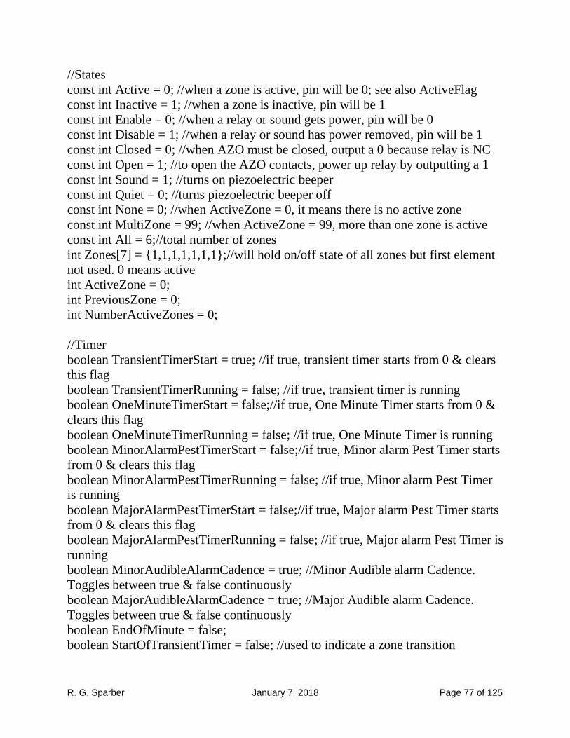
R. G. Sparber January 7, 2018 Page 77 of 125
//States
const int Active = 0; //when a zone is active, pin will be 0; see also ActiveFlag
const int Inactive = 1; //when a zone is inactive, pin will be 1
const int Enable = 0; //when a relay or sound gets power, pin will be 0
const int Disable = 1; //when a relay or sound has power removed, pin will be 1
const int Closed = 0; //when AZO must be closed, output a 0 because relay is NC
const int Open = 1; //to open the AZO contacts, power up relay by outputting a 1
const int Sound = 1; //turns on piezoelectric beeper
const int Quiet = 0; //turns piezoelectric beeper off
const int None = 0; //when ActiveZone = 0, it means there is no active zone
const int MultiZone = 99; //when ActiveZone = 99, more than one zone is active
const int All = 6;//total number of zones
int Zones[7] = {1,1,1,1,1,1,1};//will hold on/off state of all zones but first element
not used. 0 means active
int ActiveZone = 0;
int PreviousZone = 0;
int NumberActiveZones = 0;
//Timer
boolean TransientTimerStart = true; //if true, transient timer starts from 0 & clears
this flag
boolean TransientTimerRunning = false; //if true, transient timer is running
boolean OneMinuteTimerStart = false;//if true, One Minute Timer starts from 0 &
clears this flag
boolean OneMinuteTimerRunning = false; //if true, One Minute Timer is running
boolean MinorAlarmPestTimerStart = false;//if true, Minor alarm Pest Timer starts
from 0 & clears this flag
boolean MinorAlarmPestTimerRunning = false; //if true, Minor alarm Pest Timer
is running
boolean MajorAlarmPestTimerStart = false;//if true, Major alarm Pest Timer starts
from 0 & clears this flag
boolean MajorAlarmPestTimerRunning = false; //if true, Major alarm Pest Timer is
running
boolean MinorAudibleAlarmCadence = true; //Minor Audible alarm Cadence.
Toggles between true & false continuously
boolean MajorAudibleAlarmCadence = true; //Major Audible alarm Cadence.
Toggles between true & false continuously
boolean EndOfMinute = false;
boolean StartOfTransientTimer = false; //used to indicate a zone transition

R. G. Sparber January 7, 2018 Page 78 of 125
boolean LastMinuteFlowMeasurementValid = false; //is set true when flow data
updated and set false when flow data is used to change a state. It is not set false if
we just print to screen.
boolean NoTimerRunning = false; //summary flag over both transient and one
minute timers
const unsigned long TransientTimerInterval = 10000; //10000 TransienT Timer 10
seconds
#ifdef SpeedUp
const unsigned long MinorAudibleAlarmPestTimerInterval = 100000;
const unsigned long MajorAudibleAlarmPestTimerInterval = 100000;
#else
const unsigned long MinorAudibleAlarmPestTimerInterval = 86400000; //change
to 10 seconds for testing 86400000 Minor Alarm Pest Timer 24 hrs
const unsigned long MajorAudibleAlarmPestTimerInterval = 900000; //change to
10 seconds for testing 900000 Major Alarm Pest Timer 15 minutes
#endif
const unsigned long MinorAlarmOnTime = 300; //used by cadence function
const unsigned long MinorAlarmOffTime = 2000;
const unsigned long MajorAlarmOnTime = 100;
const unsigned long MajorAlarmOffTime = 100;
unsigned long TransientTimerFirstReading = millis(); //Transient Timer
unsigned long OneMinuteTimerFirstReading = millis(); //One Minute Timer
unsigned long MinorAudibleAlarmPestTimerFirstReading = millis(); //Minor
Alarm Pest timer
unsigned long MajorAudibleAlarmPestTimerFirstReading = millis(); //Major
Alarm Pest timer
unsigned long MinorAudibleAlarmCadenceTimerFirstReading = millis(); //Minor
Alarm Cadence first reading
unsigned long MajorAudibleAlarmCadenceTimerFirstReading = millis(); //Major
Alarm Cadence first reading
boolean AntiFlickerWriteOK = true;
unsigned long AntiFlickerFirstReading = millis();
unsigned long AntiFlickerUpdateTime = 10000;//LCD updates every 10 seconds
#ifdef SpeedUp
const unsigned long OneMinuteTimerInterval = 10000;
int CountDownSeconds = 20;
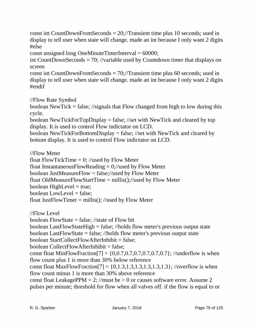
R. G. Sparber January 7, 2018 Page 79 of 125
const int CountDownFromSeconds = 20;//Transient time plus 10 seconds; used in
display to tell user when state will change. made an int because I only want 2 digits
#else
const unsigned long OneMinuteTimerInterval = 60000;
int CountDownSeconds = 70; //variable used by Countdown timer that displays on
screen
const int CountDownFromSeconds = 70;//Transient time plus 60 seconds; used in
display to tell user when state will change. made an int because I only want 2 digits
#endif
//Flow Rate Symbol
boolean NewTick = false; //signals that Flow changed from high to low during this
cycle.
boolean NewTickForTopDisplay = false; //set with NewTick and cleared by top
display. It is used to control Flow indictator on LCD.
boolean NewTickForBottomDisplay = false; //set with NewTick and cleared by
bottom display. It is used to control Flow indictator on LCD.
//Flow Meter
float FlowTickTime = 0; //used by Flow Meter
float InstantaneousFlowReading = 0;//used by Flow Meter
boolean JustMeasureFlow = false;//used by Flow Meter
float OldMeasureFlowStartTime = millis();//used by Flow Meter
boolean HighLevel = true;
boolean LowLevel = false;
float JustFlowTimer = millis(); //used by Flow Meter
//Flow Level
boolean FlowState = false; //state of Flow bit
boolean LastFlowStateHigh = false; //holds flow meter's previous output state
boolean LastFlowState = false; //holds flow meter's previous output state
boolean StartCollectFlowAfterInhibit = false;
boolean CollectFlowAfterInhibit = false;
const float MinFlowFraction[7] = {0,0.7,0.7,0.7,0.7,0.7,0.7}; //underflow is when
flow count plus 1 is more than 30% below reference
const float MaxFlowFraction[7] = {0,1.3,1.3,1.3,1.3,1.3,1.3}; //overflow is when
flow count minus 1 is more than 30% above reference
const float LeakagePPM = 2; //must be > 0 or causes software error. Assume 2
pulses per minute; threshold for flow when all valves off. if the flow is equal to or

R. G. Sparber January 7, 2018 Page 80 of 125
greater than this threshold, I flag Major Alarm. A leakage of 0.06 GPM is 87
gallons per day! At least display will show it although not alarm
float LastMinuteFlowPPM = 0;
float LastMinuteFlowGPM = 0;
float FlowCountPulse = 0;
float FlowRatePPM = 0;
float TotalFlowCount = 0; //running total of flow count while a zone is active
float TotalRunTime = 0; //running total of minutes zone is active after transient
time
float HistoricalDataPPM; //used when writing to EEPROM
const float GallonsPerPulse = 0.0280 ;//based on measurements with city meter.
//Input states
const boolean Day = true; //when light sensor output is true, it means daytime
because detector pulls up to Vcc
const boolean ActiveFlag = false; //when a zone is active, debounced read will
return false in response to seeing 0. See also Active which is an const integer and
equals 0
const boolean Pushed = false; //used by debouncedRead() of buttons
const boolean Released = true; //used by debouncedRead() of buttons
//Faults
boolean Fault = false; //fault summary flag
boolean MajorAlarm = false;
boolean AllAlarmsCleared = false;//set when CAB pushed and cleared when
display shows action.
boolean MinorAlarm[7] = {false, false, false, false, false, false, false}; //this lets
me handle multiple Minor alarms at same time although only first one is display
and available to clear. Pest blocks all of them.
boolean ZoneUnderflow[7] = {false, false, false, false, false, false, false};
boolean ZoneOverflow[7] = {false, false, false, false, false, false, false};
boolean Inhibit[7] = {false, false, false, false, false, false, false}; //when true, it
requests that zone power be removed from the active zone. ZonePower() makes the
change
boolean PESTrescindRequest = false;//if Judge Flow Rate() sees an escalation of
alarm state, it requests that Alarm Control() rescind all PESTs
boolean RelayMayBeOnSoDontLook = false; //if Alarm Control sees a manual
clear alarm, we must blind Get Zone States until relay releases
boolean SuspectRelay = false;//if the normally closed contacts on the relay are
open when the relay is off, we will get all zones on
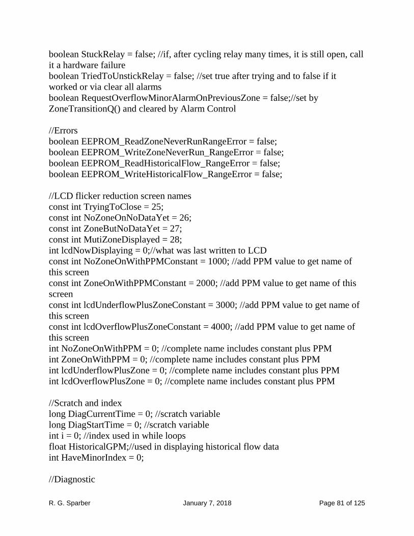
R. G. Sparber January 7, 2018 Page 81 of 125
boolean StuckRelay = false; //if, after cycling relay many times, it is still open, call
it a hardware failure
boolean TriedToUnstickRelay = false; //set true after trying and to false if it
worked or via clear all alarms
boolean RequestOverflowMinorAlarmOnPreviousZone = false;//set by
ZoneTransitionQ() and cleared by Alarm Control
//Errors
boolean EEPROM_ReadZoneNeverRunRangeError = false;
boolean EEPROM_WriteZoneNeverRun_RangeError = false;
boolean EEPROM_ReadHistoricalFlow_RangeError = false;
boolean EEPROM_WriteHistoricalFlow_RangeError = false;
//LCD flicker reduction screen names
const int TryingToClose = 25;
const int NoZoneOnNoDataYet = 26;
const int ZoneButNoDataYet = 27;
const int MutiZoneDisplayed = 28;
int lcdNowDisplaying = 0;//what was last written to LCD
const int NoZoneOnWithPPMConstant = 1000; //add PPM value to get name of
this screen
const int ZoneOnWithPPMConstant = 2000; //add PPM value to get name of this
screen
const int lcdUnderflowPlusZoneConstant = 3000; //add PPM value to get name of
this screen
const int lcdOverflowPlusZoneConstant = 4000; //add PPM value to get name of
this screen
int NoZoneOnWithPPM = 0; //complete name includes constant plus PPM
int ZoneOnWithPPM = 0; //complete name includes constant plus PPM
int lcdUnderflowPlusZone = 0; //complete name includes constant plus PPM
int lcdOverflowPlusZone = 0; //complete name includes constant plus PPM
//Scratch and index
long DiagCurrentTime = 0; //scratch variable
long DiagStartTime = 0; //scratch variable
int i = 0; //index used in while loops
float HistoricalGPM;//used in displaying historical flow data
int HaveMinorIndex = 0;
//Diagnostic

R. G. Sparber January 7, 2018 Page 82 of 125
boolean DiagOn = false; //set true to enable all instances of the Diag() tool
const int Pause = 1; //used by Diag()
const int Wait = 2; //used by Diag()
int qaz = 999; //local scratch used to calculate Diag data
//Built in Flow Simulator
boolean FastestFlow = false; //used in Flow Simulator
boolean NominalFlow = false; //used in Flow Simulator
boolean LowestFlow = false; //used in Flow Simulator
const int FlowSimulatorDivider = 1;//used by the Flow Simulator to generate rates
of 0.5, 1, and 1.5
int FlowSimulatorCount = 0; //used by the Flow Simulator to generate rates of 0.5,
1, and 1.5
//Hardware Initialization
Adafruit_MCP23017 mcp; //port expander that ties to Pro Micro via I2C
LiquidCrystal lcd(RS, EN, DB4, DB5, DB6, DB7);
void setup(){
lcd.begin(16, 2); // set up the LCD's number of columns and rows
//define each output on Arduino
pinMode(AllZonesOffPin, OUTPUT); //0 turns off relay and makes connection
pinMode(AudibleAlarmPin, OUTPUT); //1 turn on audible alarm through an NPN
pinMode(OnBoardYellowLED, OUTPUT); //on board LED for debug
digitalWrite(OnBoardYellowLED, HIGH); //turns off on board yellow LED
//Port Expander: define each input with pull ups
mcp.begin(); //using default address of 0
mcp.pinMode(0,INPUT); //define port 0 as an input
mcp.pullUp(0,HIGH); //enables 100K pull up on input
mcp.pinMode(1,INPUT);
mcp.pullUp(1,HIGH);
mcp.pinMode(2,INPUT);
mcp.pullUp(2,HIGH);
mcp.pinMode(3,INPUT);
mcp.pullUp(3,HIGH);
mcp.pinMode(4,INPUT);
mcp.pullUp(4,HIGH);
mcp.pinMode(5,INPUT);
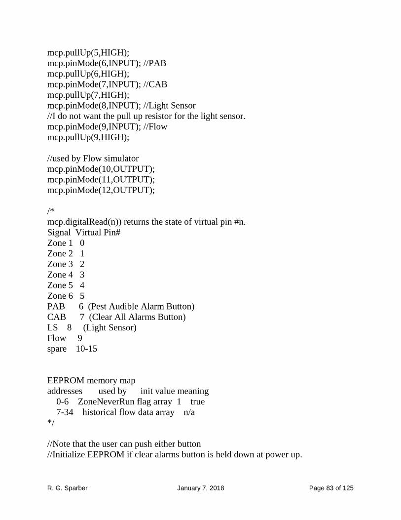
R. G. Sparber January 7, 2018 Page 83 of 125
mcp.pullUp(5,HIGH);
mcp.pinMode(6,INPUT); //PAB
mcp.pullUp(6,HIGH);
mcp.pinMode(7,INPUT); //CAB
mcp.pullUp(7,HIGH);
mcp.pinMode(8,INPUT); //Light Sensor
//I do not want the pull up resistor for the light sensor.
mcp.pinMode(9,INPUT); //Flow
mcp.pullUp(9,HIGH);
//used by Flow simulator
mcp.pinMode(10,OUTPUT);
mcp.pinMode(11,OUTPUT);
mcp.pinMode(12,OUTPUT);
/*
mcp.digitalRead(n)) returns the state of virtual pin #n.
Signal Virtual Pin#
Zone 1 0
Zone 2 1
Zone 3 2
Zone 4 3
Zone 5 4
Zone 6 5
PAB 6 (Pest Audible Alarm Button)
CAB 7 (Clear All Alarms Button)
LS 8 (Light Sensor)
Flow 9
spare 10-15
EEPROM memory map
addresses used by init value meaning
0-6 ZoneNeverRun flag array 1 true
7-34 historical flow data array n/a
*/
//Note that the user can push either button
//Initialize EEPROM if clear alarms button is held down at power up.
R. G. Sparber January 7, 2018 Page 84 of 125
if (debouncedRead(ClearAlarmButtonPin) == Pushed){ //clear EEPROM and tells
user
i=0;
while(i<7){
EEPROM.write(i,1);
i = i+1;
}
lcd.clear();
lcd.print (F("Historical"));
lcd.setCursor(0,1); //print next line on second row
lcd.print (F("data cleared."));
}
WaitUntilClearButtonReleased:
if (debouncedRead(ClearAlarmButtonPin) == Pushed) goto
WaitUntilClearButtonReleased;
//Enable Flow Meter if Pest button was held down at power up. Default is
FlowMeter() off
if (debouncedRead(PestAlarmButtonPin) == Pushed){
JustMeasureFlow = true;
lcd.print (F("Will just"));
lcd.setCursor(0,1); //print next line on second row
lcd.print (F("measure flow."));
}
WaitUntilPestButtonReleased:
if (debouncedRead(PestAlarmButtonPin) == Pushed) goto
WaitUntilPestButtonReleased;
Serial.begin(9600); //This pipes text to the PC's //Serial monitor
//Welcome screen at power up
lcd.clear();
lcd.print(F("Flow Monitor"));//the F() function prevents alphanumeric string from
be stored in scratch memory
lcd.setCursor(0,1); //print next line on second row
lcd.print (F("& Control "));
lcd.print (version);
delay(3000);
OldMeasureFlowStartTime = millis();//set starting time. Used by flow meter mode

R. G. Sparber January 7, 2018 Page 85 of 125
digitalWrite(AudibleAlarmPin, Quiet); //initialize Audible Alarm to off which is
low
}//**End of setup()
void loop(){ //TOL
JustMeasureFlowQ(); //if user just wants to measure flow, we do not return. Cancel
option with power cycle
Simulator(); //generate test Flow pulses on each pass through the loop. Selectable
via jumper plugs on board
SecondaryFlowScan();//runs often to catch narrow Flow pulses
GetZoneStates(); //returns Previous Zone and Active Zone
SecondaryFlowScan();//runs often to catch narrow Flow pulses
ZonePower(); //responds to Inhibit[] and controls zone power
SecondaryFlowScan();//runs often to catch narrow Flow pulses
TimerControl(); //all timers turned on and run from here
SecondaryFlowScan();//runs often to catch narrow Flow pulses
ZoneTransitionQ(); //Zone Transition? If so, prepare for it
SecondaryFlowScan();//runs often to catch narrow Flow pulses
ProcessFlowInfo(); // gets flow rate, displays it, and judges if flow rate is OK
SecondaryFlowScan();//runs often to catch narrow Flow pulses
RelayErrorControl();//if relay contacts fail, try to clean them
AlarmControl();//display fault details, accept manual clear of alarms, accept
pesting of active alarms, and generate audible alarms as necessary
}
//end of loop()
void GetZoneStates(){
/* GZS
Inputs: zone control lines, ActiveZone from last pass through loop,
RelayMayBeOnSoDontLook
Outputs: PreviousZone and new ActiveZone
*/
PreviousZone = ActiveZone; //save last zone state before recording new one
InitializeZone(); //set all of Zones[] to Inactive which means ones
//if Alarm Control was instructed to clear all alarms and related flags
//plus release relay, it can't be done until Zone Power so just don't look at zones
this time. Pass
//back no zones on.
R. G. Sparber January 7, 2018 Page 86 of 125
if (RelayMayBeOnSoDontLook == true){
goto FAZ;
}
PopulateZones(); //read zone pins and fill the Zones[] array
FAZ:
FindActiveZone(); //returns ActiveZone
}
//End of GetZoneStates()
void ZonePower(){ //ZP()
/*
Input: Inhibit[]
Output: control of All Zones Off relay
*/
if (Inhibit[ActiveZone] == true) {
digitalWrite(AllZonesOffPin, Open);//turn All Zones Off by operating the relay
}else{
//otherwise, ActiveZone should not be inhibited so insure it by write
digitalWrite(AllZonesOffPin, Closed);//let any zone be on by releasing the relay
(remove power from it)
}
if (RelayMayBeOnSoDontLook == true){ //I must wait after releasing the relay so
//GetZoneStates() doesn't see multizone due to floating COMMON OUT
delay(200);//wait 200 mS for relay to release but only in this special case
RelayMayBeOnSoDontLook = false; //clear flag because all is back to normal now
}
return;
}
//** End of ZonePower()
void TimerControl(){ //TC()
/*
if valve power removed due to Under or Over flow detected, wait 10 seconds for
Inhibit's effect on flow to stabilize.
*/
if ((ActiveZone != PreviousZone)&&(ActiveZone != MultiZone)){
TransientTimerStart = true; //so we have a zone transition to a single zone state or
just set Inhibit on a zone so start transient timer

R. G. Sparber January 7, 2018 Page 87 of 125
DiagStartTime = millis();//reset starting time to when TT starts. Then 10 sec for
TT followed by 1
}
if(StartCollectFlowAfterInhibit == true){
StartCollectFlowAfterInhibit = false;
TransientTimerStart = true;
DiagStartTime = millis();//reset starting time to when TT starts. Then 10 sec for
TT followed by 1 minute timer
}
TransientTimeElapseTimer();//Transient Timer
//if transient timer was just started or is running and the one minute timer was just
about to start or is running, we must Early Terminate the one minute timer
if((TransientTimerRunning == true)|| (TransientTimerStart == true)){
OneMinuteTimerStart = false;
OneMinuteTimerRunning = false;
}
/*TT starts out running. When TT done, start OM timer unless we are in
MultiZone.
*/
if ((TransientTimerRunning == false) && (OneMinuteTimerRunning == false)
&& (ActiveZone != MultiZone))OneMinuteTimerStart = true;
OneMinuteElapseTimer();//One Minute Timer
MinorPestElapseTimer();//Minor alarm Pest Timer
MajorPestElapseTimer();//Major alarm Pest Timer
MinorCadence();//Minor Alarm Cadence generator toggles
MinorAudibleAlarmCadence flag true/false
MajorCadence();//Major Alarm Cadence generator toggles
MajorAudibleAlarmCadence flag true/false
AntiFlickerCadence(); //sets the AntiFlickerWriteOK flag true every
AntiFlickerUpdateTime seconds
}
//**End of TimerControl
void ZoneTransitionQ(){//Zone Transition? ZT()
if (ActiveZone != PreviousZone){//if true, we have a zone transition
TestingNewInhibitInterruptedQ();//if inhibit was active but subsequent flow
measurement interrupted by zone change, ask for minor alarm on previous zone
SaveOldZoneFlowMeasurement(); //only does save if collected data valid

R. G. Sparber January 7, 2018 Page 88 of 125
PrepareForNewZone(); //initilizes variables
CollectFlowAfterInhibit = false;//if zone transition was during measurement
right after Inhibit invoked, we need to clean up flags
LastMinuteFlowMeasurementValid = false;
}
if (TransientTimerRunning == true){ //this signals a zone has been inhibited and
we must measure the resulting flow so reset flow variables
PrepareForNewZone(); //initilizes variables used to count flow
}
}
//End of ZoneTransitionQ()
void GetFlowRate(){
//one minute and running counts are done here
/* GFR()
Inputs: timers, Zones()
Outputs: if FlowMeasurementValid is true, LastMinuteFlowPPM is valid. Clear
this flag when data is part of a decision that comes out positive to prevent double
counting it. Flow rate while zone active is TotalFlowCount/TotalRunTime
*/
if ((ZoneOverflow[ActiveZone] == true) && (MinorAlarm[ActiveZone] ==
true)){//if we are in overflow and minor alarm has been set, stop collecting flow
data after inhibit because we are done
CollectFlowAfterInhibit = false; //clearing this flag lets Display Fault Details show
Overflow
}
FlowState = debouncedRead(FlowPin); //single read of Flow bit which is used here
and to update LCD flow symbols
digitalWrite(OnBoardYellowLED, FlowState);//echo Flow state to on board
yellow LED
if((TransientTimerStart == true) || (TransientTimerRunning == true)) return; //flow
not stable so don't measure it
if (OneMinuteTimerRunning == true){//within one minute flow sampling interval
if ((LastFlowStateHigh == true) && (FlowState == false)){
LastFlowStateHigh = false; //record that Flow is now low
FlowCountPulse = FlowCountPulse + 1;//then Flow went from high to low so
count it
FlowTickTime = millis(); //record time falling edge occurred

R. G. Sparber January 7, 2018 Page 89 of 125
NewTick = true; //set flag that a new falling edge has arrived on Flow
NewTickForTopDisplay = true; //used for top status display to show Flow activity
NewTickForBottomDisplay = true; //used for bottom status display to show Flow
activity
goto EndOfMinuteQ;
}
if ((LastFlowStateHigh == false) && (FlowState == true)){
LastFlowStateHigh = true; //record that Flow is now high
goto EndOfMinuteQ;
}
//Flow didn't change state
}
EndOfMinuteQ:
if (EndOfMinute == true){ //one minute just ended so calc flow
LastMinuteFlowPPM = FlowCountPulse;
LastMinuteFlowMeasurementValid = true;//used by Process Flow Info() and set
false after it is used to make a state change other than an LCD print
TotalFlowCount = FlowCountPulse + TotalFlowCount;//running total while zone
active
TotalRunTime = TotalRunTime + 1;//running total while zone active
FlowCountPulse = 0;//clear count for next 1 minute interval
}
return;
}
//**End of GetFlowRate()
void SecondaryFlowScan(){
//this runs multiple times in the loop to catch Flow pulses that are too narrow to be
caught
//if scanned once per cycle. Program cycle is approx 60 ms and min pulse est at
around 5 ms.
/* SRS()
Inputs: timers, Zones()
Outputs: just update flow count
*/
FlowState = debouncedRead(FlowPin);//do single read of Flow and then process it
plus I use it to toggle LCD flow status symbols
digitalWrite(OnBoardYellowLED,FlowState);//echo Flow state to on board yellow
LED

R. G. Sparber January 7, 2018 Page 90 of 125
if((TransientTimerStart == true) || (TransientTimerRunning == true)) return; //flow
not stable so don't measure it
if (OneMinuteTimerRunning == true){//within one minute flow sampling interval
if ((LastFlowStateHigh == true) && (FlowState == false)){
LastFlowStateHigh = false; //record that Flow is now low
FlowCountPulse = FlowCountPulse + 1;//then Flow went from high to low so
count it
FlowTickTime = millis(); //record time falling edge occurred
NewTick = true; //set flag that a new falling edge has arrived on Flow
NewTickForTopDisplay = true;
NewTickForBottomDisplay = true;
}
if ((LastFlowStateHigh == false) && (FlowState == true)){
LastFlowStateHigh = true; //record that Flow is now high
}
//Flow didn't change state
}
return;
}
// ** End of SecondaryFlowScan()
void DisplayFlowRate(){ //DFR()
//display the flow rate. Note that this is only sunny day. Rainy day displays done in
Alarm Control()
LastMinuteFlowGPM = LastMinuteFlowPPM*GallonsPerPulse;
if (SuspectRelay == true)return; //block all non fault messages if relay contacts
seem to be faulted
if (MoreThanOne() == true)return;
if (PossibleFault() == true)return;//if we have a fault or have just invoked Inhibit,
we don't want alarm message erased by nonfault flow info
if (NoZoneOnAndNoDataYet() == true)return;
if (NoZoneOnWithData() == true)return;
if (ActiveZoneNoDataYet() == true)return;
if (ZoneActive() == true)return;
}
//** End of DisplayFlowRate()

R. G. Sparber January 7, 2018 Page 91 of 125
void JudgeFlowRate(){ //JFR()
/*
Inputs: LastMinuteFlowPPM and flow references
Outputs: MinorAlarm[ActiveZone], Major Alarm, Fault flag.
ZoneUnderflow(ActiveZone), ZoneOverflow(ActiveZone). Major Alarm is not
tied to any zone. Fault is tied to current ActiveZone
Judge Flow Rate looks at LastMinuteFlowPPM only if
LastMinuteFlowMeasurementValid is true to determine if in spec. Once
LastMinuteFlowPPM is used to make a state change
(not just to print to LCD), LastMinuteFlowMeasurementValid is set to false so I
don't use the reading again. If LastMinuteFlowPPM is not within range, it sets
Inhibit[ActiveZone] to true. On the next pass through, it evaluates the flow to see if
the inhibit worked.
*/
if(MajorAlarm == true)return; //Once we reach Major Alarm, no flow judging is
done.
if(MultiZoneQ == true) return;
if (NoFlowDataQ() == true)return;
if(NoHistoryQ() == true)return;
if(SmallFlowQ() == true)return;//if flow is small, include uncertainty of readings to
determine if normal or Overflow. Return if normal or overflow set.
if(UnderflowQ() == true)return;
if(OverflowBeforeInhibitQ() == true)return;
if(ImmediatelyAfterInhibitFaultQ() == true)return;//if Inhibit was just invoked and
first flow data taken, set Minor Alarm if it held. If it didn't hold, set Major Alarm.
if (AfterInhibitStableFaultQ() == true)return;// if true, Inhibit not holding anymore,
we have Overflow Major
if(LeakageNoZonesActiveQ() == true)return;
/*
To get here, flow must be within normal range. Note that once a zone has been
inhibited, it can only be cleared manually. Otherwise, I would
have to turn on the suspect zone periodically and see if the problem
still there. Since manual intervention needed to fix the problem,
makes sense to just make alarm clear manual.
*/
}
//**End of JudgeFlowRate()

R. G. Sparber January 7, 2018 Page 92 of 125
void TransientTimeElapseTimer(){//** TTE()
if (ActiveZone == MultiZone){ //stop TT timer if MultiZone active
DiagStartTime = millis();//reset starting time to when TT starts. Then 10 sec
for TT followed by 1
TransientTimerStart = false;
TransientTimerRunning = false;
return;
}
NoTimerRunning =((TransientTimerStart == false) &&
(TransientTimerRunning == false) && (OneMinuteTimerStart == false) &&
(OneMinuteTimerRunning == false));
if ((PreviousZone == MultiZone) && (NoTimerRunning == true)){
TransientTimerStart = true; //while in MultiZone, all timers were stopped but
now that we have left, start the TT
DiagStartTime = millis();//reset starting time to when TT starts. Then 10 sec for
TT followed by 1
}
if (TransientTimerStart == true){
LastMinuteFlowMeasurementValid = false; //will be true after first minute
passes and the first Flow data has been generated
StartOfTransientTimer = true;//used to indicate a zone transition NOT USED
TransientTimerStart = false;
DiagStartTime = millis();//reset starting time to when TT starts. Then 10 sec
for TT followed by 1
TransientTimerFirstReading = millis();
TransientTimerRunning = true;
CountDownSeconds = CountDownFromSeconds; //since this is the start of
transient interval, initialize countdown
return;
}
//When TT done, clear TransientTimerRunning flag
if (TransientTimerRunning == true){
CountDownSeconds = CountDownFromSeconds - (millis() -
TransientTimerFirstReading)/1000; //start at CountDownFrom and count down to
60. Then OM takes over
if ((millis() - TransientTimerFirstReading) >= TransientTimerInterval){ //so
transient interval is over
TransientTimerRunning = false;
R. G. Sparber January 7, 2018 Page 93 of 125
CountDownSeconds = OneMinuteTimerInterval/1000; // count down during
transient is done so prepare for one minute count down
return;
}
}
}
//** end of TransientTimeElapseTimer()
void OneMinuteElapseTimer(){//**one minute timer OME()
if (ActiveZone == MultiZone){//stop OM timer if MultiZone active
OneMinuteTimerStart = false;
OneMinuteTimerRunning = false;
EndOfMinute = false;
return;
}
if (OneMinuteTimerStart == true){
EndOfMinute = false;
OneMinuteTimerStart = false;
OneMinuteTimerFirstReading = millis();
OneMinuteTimerRunning = true;
CountDownSeconds = OneMinuteTimerInterval/1000;
return;
}
if (OneMinuteTimerRunning == true){
CountDownSeconds = OneMinuteTimerInterval/1000. - (millis() -
OneMinuteTimerFirstReading)/1000; //CountDown timer used on screen when
flow being displayed.
if ((millis() - OneMinuteTimerFirstReading) >= OneMinuteTimerInterval){ //if
timer done
OneMinuteTimerRunning = false;
EndOfMinute = true;
return;
}
}
}
//**end of OneMinuteElapseTimer()
void MinorPestElapseTimer(){//**Minor alarm Pest Timer MIPE()
if (MinorAlarmPestTimerStart == true){
R. G. Sparber January 7, 2018 Page 94 of 125
digitalWrite(AudibleAlarmPin, Quiet); //turns sound off
MinorAlarmPestTimerStart = false;
MinorAudibleAlarmPestTimerFirstReading = millis();
MinorAlarmPestTimerRunning = true;
return;
}
if ((MinorAlarmPestTimerRunning == true) && ((millis() -
MinorAudibleAlarmPestTimerFirstReading) >=
MinorAudibleAlarmPestTimerInterval))MinorAlarmPestTimerRunning = false;
return;
}
//**end of MinorPestElapseTimer()
void MajorPestElapseTimer(){//**Major alarm Pest Timer MAPE()
if (MajorAlarmPestTimerStart == true){
digitalWrite(AudibleAlarmPin, Quiet); // be sure sound is off
MajorAlarmPestTimerStart = false;
MajorAudibleAlarmPestTimerFirstReading = millis();
MajorAlarmPestTimerRunning = true;
return;
}
if ((MajorAlarmPestTimerRunning == true) && ((millis() -
MajorAudibleAlarmPestTimerFirstReading) >=
MajorAudibleAlarmPestTimerInterval))MajorAlarmPestTimerRunning = false;
return;
}
//**end of MajorPestElapseTimer()
void MinorCadence(){ //**Minor Cadence Timer Subroutine MiC()
if (MinorAudibleAlarmCadence == true){
if ((millis() - MinorAudibleAlarmCadenceTimerFirstReading) <
MinorAlarmOnTime)return;
MinorAudibleAlarmCadence = false; //change timer from true to false
MinorAudibleAlarmCadenceTimerFirstReading = millis();//reset timer for use by
MIACC being false
}else{
if ((millis() - MinorAudibleAlarmCadenceTimerFirstReading) <
MinorAlarmOffTime)return;
R. G. Sparber January 7, 2018 Page 95 of 125
MinorAudibleAlarmCadence = true; //change timer from false to true
MinorAudibleAlarmCadenceTimerFirstReading = millis();//reset timer for use by
MIACC being true
}
return;
}
//**End of MinorCadence()
void MajorCadence(){ //**Major Cadence Timer Subroutine
if (MajorAudibleAlarmCadence == true){
if ((millis() - MajorAudibleAlarmCadenceTimerFirstReading) <
MajorAlarmOnTime)return;
MajorAudibleAlarmCadence = false; //change timer from true to false
MajorAudibleAlarmCadenceTimerFirstReading = millis(); //reset timer for use
by MAACC being false
AntiFlickerWriteOK = true;//UNRELATED TO ALARM CADENCE: once
every MajorAlarmOnTime interval we will update the LCD to reduce flicker
}else{
if ((millis() - MajorAudibleAlarmCadenceTimerFirstReading) <
MajorAlarmOffTime)return;
MajorAudibleAlarmCadence = true;//change timer from false to true
MajorAudibleAlarmCadenceTimerFirstReading = millis();//reset timer for use
by MAACC being true
}
return;
}
//**End of MajorCadence()
void AntiFlickerCadence(){ //generates a flag that is set true every
AntiFlickerUpdateTime seconds. It is cleared when any screen is updated
if ((millis() - AntiFlickerFirstReading) < AntiFlickerUpdateTime)return;//if not
time to set AntiFlickerWriteOK flag, just return
AntiFlickerWriteOK = true; //time to set the flag true
AntiFlickerFirstReading = millis(); //reset timer for use by AntiFlickerWriteOK
being set true
return;
}

R. G. Sparber January 7, 2018 Page 96 of 125
//**End of AntiFlickerCadence()
void ProcessFlowInfo(){ //flow is in pulses per minutes except when being
displayed
GetFlowRate();
DisplayFlowRate();
JudgeFlowRate();
}
//** End of ProcessFlowInfo()
void AlarmControl(){ //** AC()
/*
Inputs: alarm states, Inhibit(), pushbuttons
Outputs: audible alarms, LCD display text, cleared error arrays
*/
CleanUpPrematureAlarmExit();//if zone change occurred during flow
measurement immediately after Inhibit true, force MinorAlarm on the zone as best
guess
DisplayFaultDetails(); //if there is a software fault, stop the program; otherwise
display and return
ManuallyClearAlarmQ();
PestActiveAlarmQ();
AudibleAlarmProcessing();
}
//**End of AlarmControl()
void SaveOldZoneFlowMeasurement(){ //SOZFM()
//only save historical flow data that is not from faulted zone or Multizone and is
from at least one minute of measuring flow
if ((TotalRunTime == 0) || (Inhibit[PreviousZone] == true) ||
(MinorAlarm[PreviousZone] == true) || (MajorAlarm == true) || (PreviousZone ==
MultiZone))return;
//no save if past flow data not valid. However, when CAB pushed, all of these are
cleared so should cause return.
//otherwise, save the past flow data
HistoricalDataPPM = TotalFlowCount/TotalRunTime; //the new historical data in
PPM is the average rate over the full time the zone was just running
WriteHistoricalFlow(PreviousZone, HistoricalDataPPM);
WriteZoneNeverRun(PreviousZone, false); //this zone's historical data is now valid
R. G. Sparber January 7, 2018 Page 97 of 125
}
//end of SaveOldZoneFlowMeasurement()
void PrepareForNewZone(){ //PFNZ()
FlowCountPulse = 0;//initialize since new zone active
TotalFlowCount = 0;//initialize since new zone active
TotalRunTime = 0;//initialize since new zone active
}
//end of PrepareForNewZone()
void InitializeZone(){ //IZ()
/*
Inputs: none
Outputs: Zones[]
Desc: sets all elements of Zones[] to Inactive
*/
i=0;
while(i<7){
Zones[i]=Inactive;
i=i+1;
}
}
//**End of InitializeZone()
void PopulateZones(){ //read zone pins and fill the Zones() array
//if COM disconnected but one zone active, all zones will appear active
if (debouncedRead(Zone1Pin) == ActiveFlag)Zones[1] = Active;
if (debouncedRead(Zone2Pin) == ActiveFlag)Zones[2] = Active;
if (debouncedRead(Zone3Pin) == ActiveFlag)Zones[3] = Active;
if (debouncedRead(Zone4Pin) == ActiveFlag)Zones[4] = Active;
if (debouncedRead(Zone5Pin) == ActiveFlag)Zones[5] = Active;
if (debouncedRead(Zone6Pin) == ActiveFlag)Zones[6] = Active;
}
//**End of PopulateZones()
void FindActiveZone(){
i = 1;

R. G. Sparber January 7, 2018 Page 98 of 125
NumberActiveZones = 0;//initialize count of active zones
while(i<7){ //count number of active zones
if (Zones[i] == Active)NumberActiveZones = NumberActiveZones + 1;
i=i+1;
}
if (NumberActiveZones == 0){//no zones are active
//with no zones active, we can't tell if relay not stuck so if SusprectRelay was true,
leave it there
ActiveZone = None;
return;
}
if (NumberActiveZones == 1){//identify the one active zone
SuspectRelay = false;//with only 1 active zone, relay can't be stuck
i = 1;
while(i<7){
if (Zones[i] == Active){
ActiveZone = i;
return; //found the active zone so stop looking
}
i=i+1;
}
}
//otherwise, more than 1 zone is active or relay is active
//if Inhibit is active, COM has been disconnected and the ActiveZone backfeeds
the zones that are off
//to cause them all to look active. Therefore, just return so the previous ActiveZone
value persists.
if (Inhibit[ActiveZone] == true){
return;
}
//if all zones are active but Inhibit not true, it is likely that the relay contacts have
oxides on them which prevents them closing when the relay is released
if (NumberActiveZones == All){
SuspectRelay = true; //relay contacts may not have closed but also call it
MultiZone
}
//Since Inhibit not active, assume NumberActiveZones > 1 due to user action so
have Multizone
ActiveZone = MultiZone;
return;
R. G. Sparber January 7, 2018 Page 99 of 125
}
//** End of FindActiveZone()
void DisplayFaultDetails(){//DFD()
if (RelayErrorQ()==true) return;
if(CABpressed()==true)return;
if (SoftwareError() == true)return;
if(CannotStop() == true)return;
if (Trying() == true)return;
if(HaveMinor() == true)return;
}
//** end of DisplayFaultDetails()
void ManuallyClearAlarmQ(){//manually clear alarm?
if (debouncedRead(ClearAlarmButtonPin) == Pushed){
//clears Major or all Minor alarms; put all flags back to init state except a few
AllAlarmsCleared = true; //used to control display managed by Alarm Control()
TransientTimerStart = true;//start timing sequence the same as a zone change
TransientTimerRunning = false;
TotalRunTime = 0; //this prevents bad flow data from being saved in historical
OneMinuteTimerStart = false;
OneMinuteTimerRunning = false;
MinorAlarmPestTimerStart = false;
MajorAlarmPestTimerStart = false;
EndOfMinute = false;
StartOfTransientTimer = false;
LastMinuteFlowMeasurementValid = false;
NoTimerRunning = false;
FlowState = false;
EEPROM_ReadZoneNeverRunRangeError = false;
EEPROM_WriteZoneNeverRun_RangeError = false;
EEPROM_ReadHistoricalFlow_RangeError = false;
EEPROM_WriteHistoricalFlow_RangeError = false;
SuspectRelay = false;
CollectFlowAfterInhibit = false;//Inhibit[] cleared below but must also clear this
flag
StartCollectFlowAfterInhibit = false;
MajorAlarm = false;
Fault = false;

R. G. Sparber January 7, 2018 Page 100 of 125
MajorAlarmPestTimerRunning = false; //in case Major Pest timer running, turn
it off
i = 0;
while(i<7){
MinorAlarm[i] = false;
Inhibit[i] = false;
RelayMayBeOnSoDontLook = true; //tells Get Zone States to not look because
if relay is operated it will see multizone
ZoneUnderflow[i] = false;
ZoneOverflow[i] = false;
MinorAlarmPestTimerRunning = false; //in case Minor Pest timer running,
turn it off
i=i+1;
}
//this is a violation of the architecture because it is a display function not done in
a display subroutine. Must do it here because we stay in a tight loop until CAB
released and need positive feedback to user.
lcd.clear();
lcd.print (F("Cleared"));
lcd.setCursor(0,1); //print starting at col 0 row 1
lcd.print (F("all alarms."));
WaitForClearButtonRelease:
if (debouncedRead(ClearAlarmButtonPin) == Pushed)goto
WaitForClearButtonRelease; //user will hear audible alarm go away so wait until
they let go of clear button
lcd.clear();
}
} //end of ManuallyClearAlarmQ()
void PestActiveAlarmQ(){
if(PESTrescindRequest == true){
//Judge Flow Rate() has requested that Major and Minor Alarm PEST be rescinded
because new alarm has arrived
MinorAlarmPestTimerStart = false;//stops Minor alarm Pest Timer
MinorAlarmPestTimerRunning = false; //stops Minor alarm Pest Timer
MajorAlarmPestTimerStart = false;//stops Major alarm Pest Timer
MajorAlarmPestTimerRunning = false; //stops Major alarm Pest Timer
PESTrescindRequest = false;//clear rescind flag
return;
R. G. Sparber January 7, 2018 Page 101 of 125
}
if (debouncedRead(PestAlarmButtonPin) == Pushed){
lcd.clear();//after pesting alarms, acknowledge button pushed
lcd.print (F("Silenced"));
lcd.setCursor(0,1); //print starting at col 0 row 1
lcd.print (F("audible alarms."));
//pest any audible alarms
if(MajorAlarm == true){
MajorAlarmPestTimerStart = true; //starts the Major Alarm Pest timer
}
//if any zone has MinorAlarm, start Minor Alarm Pest timer
i = 1;
while(i<7){
if (MinorAlarm[i] == true){
MinorAlarmPestTimerStart = true; //start the Minor alarm pest timer
goto WaitForPestButtonRelease;
}
i=i+1;
}
WaitForPestButtonRelease:
if (debouncedRead(PestAlarmButtonPin) == Released){
lcd.clear();
return;
}else{
goto WaitForPestButtonRelease; //user will stop hearing audible alarm when they
let go of Pest button
}
}
}
// end of PestActiveAlarmQ()
void AudibleAlarmProcessing(){
if(MajorAlarmPestTimerRunning == true)return; //Major audible alarm Pested so
just leave audible alarm generation
if (MajorAlarm == true){
if(MajorAudibleAlarmCadence == true){ //if cadence says time to beep, do it
digitalWrite(AudibleAlarmPin, Sound); //turn on sound
}else{
digitalWrite(AudibleAlarmPin, Quiet); //turns sound off
R. G. Sparber January 7, 2018 Page 102 of 125
}
return; //by leaving audible alarm generation now, we prevent having both a
Major and Minor alarm at the same time. Only the Major will sound.
}
//there is no Major Alarm but there might be a Minor
if (MinorAlarmsActiveQ() == false){//no Minor Alarms so be sure piezo is quiet
and return
digitalWrite(AudibleAlarmPin, Quiet);
return;
}//otherwise we have a Minor Alarm
if(MinorAlarmPestTimerRunning == true){ //Minor audible alarm Pested so return
digitalWrite(AudibleAlarmPin, Quiet);
return;
}//have at least one Minor Alarm that is not pested
if (debouncedRead(LightSensorPiin) == Day){
//it is daytime so sound it
if(MinorAudibleAlarmCadence == true){ //if cadence says time to beep, do it
digitalWrite(AudibleAlarmPin, Sound);
}else{
digitalWrite(AudibleAlarmPin, Quiet); //turns sound off
}
}else{
digitalWrite(AudibleAlarmPin, Quiet); //be sure audible alarm is off at night
}
return; // then it is night so do not sound Minor audible alarm even if active
}
// **end of AudibleAlarmProcessing()
boolean ReadZoneNeverRun(byte zone){
/*
EEPROM memory map
addresses used by init value meaning
0-6 ZoneNeverRun flag array 1 true
7-34 historical flow data array n/a
*/
boolean flag;
if (zone > 6){
EEPROM_ReadZoneNeverRunRangeError = true;

R. G. Sparber January 7, 2018 Page 103 of 125
return true;
}
if (zone == None) return false; //since we use Leakage limit for No zones on, we
always have historical data so can say it has always run before
flag = EEPROM.read(zone);
return flag;
} //end of ReadZoneNeverRun()
void WriteZoneNeverRun(int zone, boolean data){
/*
EEPROM memory map
addresses used by init value meaning
0-6 ZoneNeverRun flag array 1 true
7-34 historical flow data array n/a
*/
if (zone > 6){
EEPROM_WriteZoneNeverRun_RangeError = true;
return;
}
if (zone == None) return;//no need to write because we use Leakage as historical so
it is as if we have always previously run for this case
EEPROM.write(zone, data);
} //end of WriteZoneNeverRun()
float ReadHistoricalFlowPPM(int zone){
/*
EEPROM memory map
addresses used by init value meaning
0-6 ZoneNeverRun flag array 1 true
7-34 historical flow data array n/a
*/
int address;
float data;
if (zone == None)return LeakagePPM;//when no zones on, we use Leakage as our
historical
if (zone > 6){
EEPROM_ReadHistoricalFlow_RangeError = true;
return 0;

R. G. Sparber January 7, 2018 Page 104 of 125
}
address = (zone * 4) + 7; //points to lowest byte in float variable
EEPROM.get(address,data);
return data;
} //end of ReadHistoricalFlow
void WriteHistoricalFlow(int zone,float data){
/*
EEPROM memory map
addresses used by init value meaning
0-6 ZoneNeverRun flag array 1 true
7-34 historical flow data array n/a
*/
int address;
if (zone == None) return; //nothing to write because we use Leakage
if (zone > 6){
EEPROM_WriteHistoricalFlow_RangeError = true;
return;
}
address = (zone * 4) + 7;
EEPROM.put(address,data);
} //end of WriteHistoricalFlow
void SoftwareFaultBeep(){ //0.1 second on and 10 seconds off
SFB:
digitalWrite(AudibleAlarmPin, Sound);
delay (100);
digitalWrite(AudibleAlarmPin, Quiet);
delay (10000);
goto SFB;
} // end of SoftwareFaultBeep
void Diag(int marker, int data, int control){ //diagnostic tool; control can be Pause
or Wait. Pause is for 5 seconds. Wait is until Pest pushed and released
if (DiagOn == false) return; //default is all instances of this diagnostic tool off.
Turn them on by holding down only the Pest button at power up.

R. G. Sparber January 7, 2018 Page 105 of 125
/*
Inputs:
marker - identify of this instance of Diag()
data - an integer to be displayed
control - what to do when data is displayed
* Pause - delay 3 seconds and then return
* Wait - wait until the Pest button is pushed and then return
*/
delay (3000); //give time for last LCD message to be seen.
lcd.clear();
lcd.print (F("ID "));
lcd.print(marker);
lcd.setCursor(0,1); //print starting at col 0 row 1
lcd.print (F("Data "));
lcd.print (data);
if (control == Pause){
delay(3000); //wait 3 seconds
lcd.clear(); //clean up display
return;
}
if (control == Wait){
ScanPestButton:
if(debouncedRead(PestAlarmButtonPin) == Pushed){
//clean up display; next wait for Pest to be pushed and then wait for it to be
released
lcd.clear(); //when Pest is pushed, clear the display
if (debouncedRead(PestAlarmButtonPin) != Pushed)return; //when Pest is then
released, return
}
goto ScanPestButton; //keep scanning for Pest to be pushed and released
}
//control is not Pause or Wait so tell user they didn't specify a valid Control type,
wait 5 seconds, clean up, and return
lcd.clear();
lcd.print (F("ID "));
lcd.print(marker);
lcd.setCursor(0,1); //print next line on second row
lcd.print (F("Control?")); //was Control

R. G. Sparber January 7, 2018 Page 106 of 125
delay(5000); //wait 5 seconds
lcd.clear();
return;
} // **end of Diag()
boolean MinorAlarmsActiveQ(){ //return true if we have at least one Minor
Alarms
if(StuckRelay == true)return true;//a stuck relay is a minor alarm
i = 1;
while(i<7){
if(MinorAlarm[i] == true)return true;
i=i+1;
}
return false; //no Minor Alarms exist
} // end of MinorAlarmsActiveQ
//Debounced Read of an input on the MCP23017
boolean debouncedRead(int Pin){//this is the only place a local variable is used and
passed back as the value of a subroutine
float debounce = 0;
float reading;
i = 0;
while (i<10){//read pin 10 times and take average rounded to nearest int
//note that read is from port expander and not from Arduino pin
reading = float(mcp.digitalRead(Pin));
debounce = reading + debounce;
i = i+1;
}
debounce = round((debounce/10));//take average and round to nearest integer but
debounce is still float
if (debounce <= 0.5)return false;
// fall through to signal must be > 0.5 so true
return true;
}
//**End of port expander Debounced Read.
void PrintStatusTop(){//puts day/night, flow activity, and countdown timer in top
right corner
R. G. Sparber January 7, 2018 Page 107 of 125
lcd.setCursor(12,0); //column, row
if (debouncedRead(LightSensorPiin) == Day){
if((MajorAlarmPestTimerRunning == false)&&(MinorAlarmPestTimerRunning
== false)){
lcd.print (F("D"));//daytime with no active pests
}else{
lcd.print (F("d"));//daytime with an active pest
}
}else{//is night
if(MajorAlarmPestTimerRunning == false){
lcd.print (F("N"));//nighttime with no active pests
}else{
lcd.print (F("n"));//nighttime with an active pest
}
}
if (TransientTimerRunning == true){//we are in the transient interval so ignoring
flow
lcd.print (F("T"));
}else{//we are measuring flow for 1 minute so show flow activity
if (NewTickForTopDisplay == true){ //when a falling edge detected on this cycle,
show a "]".
lcd.print (F("]"));
NewTickForTopDisplay = false; //clear Flow edge flag in preparation for next
falling edge
}else{ //when there has not been a falling edge, show a "[".
lcd.print(F("["));
}
}
if(CountDownSeconds < 10)lcd.print(F(" ")); //going from 2 digits to 1 digit so
shift count over 1 space
lcd.print(CountDownSeconds);
}
//** end of PrintStatusTop()
void PrintStatusBottom(){//puts countdown timer in bottom right corner along with
flow indicator. It does not show day/night or pest status.
lcd.setCursor(13,1); //so 3 character positions left on second line
if (TransientTimerRunning == true){//we are in the transient interval so ignoring
flow
R. G. Sparber January 7, 2018 Page 108 of 125
lcd.print (F("T"));
}else{//we are measuring flow for 1 minute so show flow activity
if (NewTickForBottomDisplay == true){ //when a falling edge detected on this
cycle, show a "]".
lcd.print (F("]"));
NewTickForBottomDisplay = false;
}else{ //when there has not been a falling edge, show a "[".
lcd.print (F("["));
}
}
if(CountDownSeconds < 10)lcd.print(F(" "));//going from 2 digits to 1 digit so
shift count over 1 space
lcd.print (CountDownSeconds);
}
//**end of PrintStatusBottom()
//Flow Simulator executes on each pass of the loop but only increments its count
every "FlowSimulatorDivider" times.
void Simulator(){
if (FlowSimulatorCount < 1){
FlowSimulatorCount = FlowSimulatorDivider;//reset the count
//ripple counter to divide down fastest rate
if (FastestFlow == false){//it toggles each time we have count down to 0
//FastestFlow falling edge
FastestFlow = true;
mcp.digitalWrite(12,HIGH);
if (NominalFlow == false){ //each time the fastest flow rises, toggle the nominal
rate
//Nominal Flow rising edge
NominalFlow = true;
mcp.digitalWrite(11,HIGH);
if (LowestFlow == false){
LowestFlow = true;
mcp.digitalWrite(10,HIGH);
//digitalWrite(OnBoardYellowLED, HIGH); //drive yellow LED on the board
too
}else{
LowestFlow = false;
mcp.digitalWrite(10,LOW);

R. G. Sparber January 7, 2018 Page 109 of 125
//digitalWrite(OnBoardYellowLED, LOW);//drive yellow LED on the board
too
}
}else{
NominalFlow = false;
mcp.digitalWrite(11,LOW);
}
}else{
FastestFlow = false;
mcp.digitalWrite(12,LOW);
}
}
-- FlowSimulatorCount; //decrement Flow Simulator Counter
}
//end of Simulator()
void PrintLastMinuteFlowGPM(){ //does rounding based on size of number so it
fits into 4 character positions
if (LastMinuteFlowGPM >= 10.) {// xx.x
lcd.print (LastMinuteFlowGPM,1); //print looks at the variable and sees it is a
float so rounds to 1 place
}
if (LastMinuteFlowGPM < 10.){//x.xx or 0.xx
lcd.print (LastMinuteFlowGPM,2);//print looks at the variable and sees it is a
float so rounds to 2 place
}
}
boolean MultiZoneQ(){
if (ActiveZone == MultiZone){//don't judge flow if in Multi Zone
return true;
}else{
return false;
}
}
boolean NoFlowDataQ(){//see if we have no flow data yet for what appears to be a
healthy ActiveZone.
if ((TotalRunTime == 0) && (Inhibit[ActiveZone] == false)){//Assume no fault.
R. G. Sparber January 7, 2018 Page 110 of 125
return true; //We have no historical flow data to use as reference. No zone active
has Leakage limit so can proceed. Assume no fault.
}else{
return false;
}
}
boolean NoHistoryQ(){//see if we have no historical flow data to use as reference.
No zone active has Leakage limit so can proceed.
if (ReadZoneNeverRun(ActiveZone) == true){//Assume no fault.
return true;
}else{
return false;
}
}
boolean ImmediatelyAfterInhibitFaultQ(){
if((CollectFlowAfterInhibit == false) || (LastMinuteFlowMeasurementValid ==
false))return false; //if we are not waiting for flow data
//right after Inhibit enabled or new measured data not available yet, return false.
//zone has just been inhibited and data good, see if flow has been controlled
LastMinuteFlowMeasurementValid = false;//we are about to use
LastMinuteFlowPPM so it is no longer valid.
//we know flow isn't right because Inhibit just invoked but do not know the new
alarm state yet. Therefore
//leave old alarm state in place along with state of PEST
Fault = true;//since we do know a new alarm state will be found soon, set fault
summary flag true
CollectFlowAfterInhibit = false; //finally can retire this flag because collected
data after inhibit was used to set an alarm. Data's value now used up
PESTrescindRequest = true; //we are reaching a new alarm state so be sure PEST
rescinded
ZoneOverflow[ActiveZone] = true;//since Inhibit was set active, we know
Overflow exists. Must next determine if Minor or Major
if(LastMinuteFlowPPM < LeakagePPM){
//inhibit did work so we have just arrived at Overflow Minor Alarm
MinorAlarm[ActiveZone] = true;
}else{//the LastMinuteFlowPPM >= LeakagePPM //inhibit did not work so we
have just arrived at Overflow Major Alarm
R. G. Sparber January 7, 2018 Page 111 of 125
MajorAlarm = true; //zone inhibited and it did not work so Overflow Major
Alarm
}
return true; //return true because an alarm always results from Inhibit first going
active
}
// ** End of ImmediatelyAfterInhibitFaultQ()
boolean AfterInhibitStableFaultQ(){
if((Inhibit[ActiveZone] == false) || (CollectFlowAfterInhibit == true) ||
(LastMinuteFlowMeasurementValid == false))return false;
//We are already at Overflow Minor. Monitor flow to be sure blocked flow persists.
if(LastMinuteFlowPPM >= LeakagePPM){
//inhibit was working but has now failed so we have moved from Overflow Minor
to Overflow Major Alarm
//I will be coming back here when Inhibit true in the minor alarm case. We just
escalated to major.
MinorAlarm[ActiveZone] = false; //we keep fault type at Overflow but retire
Minor.
MajorAlarm = true; //set new alarm level
PESTrescindRequest = true; //we are changing alarms so be sure PEST rescinded
return true; //have new alarm state
}else{ //LastMinuteFlowPPM is < LeakagePPM so are holding at Overflow
Minor
return false; //no new alarm state
}
}
// ** End of AfterInhibitStableFaultQ()
boolean SmallFlowQ(){//if small flow, guard against 0/0 and do best to determine
if normal or overflow
//note that historical flow, i.e, ref, is an average so can be fractional. Flow is a
count so is an integer
if((ZoneUnderflow[ActiveZone] == true) || (ZoneOverflow[ActiveZone] == true) ||
(LastMinuteFlowMeasurementValid == false))return false;//no valid data to
evaluate
if(ReadHistoricalFlowPPM(ActiveZone) < 1.43){

R. G. Sparber January 7, 2018 Page 112 of 125
//given a ref of less than 1.43, can't have underflow. (flow+1)/ref = 0.7 so at flow
of 0, ref = 1.43
if (LastMinuteFlowPPM <= 3){ //0, 1, 2, or 3 is normal flow
goto CallItNormal;
}else{ //4 or higher is overflow. (flow-1)/ref = 1.3 so at ref of 1.43, flow = 2.86.
Therefore, 3 +/- 1 is overflow
goto CallItOverflow;
}
}else{
return false; //there was no small flow so can use the regular logic to determine
underflow, normal, and overflow
}
CallItNormal:
LastMinuteFlowMeasurementValid = false;//I used
LastMinuteFlowMeasurementValid to make a state change so has now been used
up
return true;
CallItOverflow:
PESTrescindRequest = true;//we are about to arrived at a new alarm state so
request that any PESTed audible alarms be rescinded
ZoneOverflow[ActiveZone] = true;//have Overflow so next try Inhibit() and go
around loop again.
ZoneUnderflow[ActiveZone] = false;//if we were in Underflow, retire that flag
since we just went to Overflow
Inhibit[ActiveZone] = true;
CollectFlowAfterInhibit = true;
LastMinuteFlowMeasurementValid = false;//I used
LastMinuteFlowMeasurementValid to make a state change so has now been used
up
StartCollectFlowAfterInhibit = true; //tells Timer Control() to set
TransientTimerStart true and that starts new flow measurement. It then clears this
flag so we don't continuously restart TT.
//Fault summary flag not set yet because we don't know if Minor or Major
return true;
}
boolean UnderflowQ(){
if (ActiveZone == None){
return false; //there can't be underflow when no zones active
}
R. G. Sparber January 7, 2018 Page 113 of 125
if ((Inhibit[ActiveZone] == false) && (ZoneOverflow[ActiveZone] == false)
&&(LastMinuteFlowMeasurementValid == true) &&((LastMinuteFlowPPM +
1)/ReadHistoricalFlowPPM(ActiveZone)) < MinFlowFraction[ActiveZone]){
//we have Underflow.
MinorAlarm[ActiveZone] = true; //no retesting of flow needed so just declare
Minor Alarm
Fault = true; // no retesting of flow needed so just declare Fault
ZoneUnderflow[ActiveZone] = true; //set Underflow flag for this zone
LastMinuteFlowMeasurementValid = false;//we used LastMinuteFlowPPM so it
is no longer valid
return true;
}else{
return false;
}
}
boolean LeakageNoZonesActiveQ(){
//all flow measurements are +/- 1 pulse. When LastMinuteFlowPPM is only a few
pulses per minute, +/- 1 pulse is a large percentage.
//Therefore I will decrease LastMinuteFlowPPM by 1 for Overflow
//see if we have excessive flow when no zones are active
if ((ActiveZone == None) && (LastMinuteFlowPPM > LeakagePPM)){//if flow is
greater than leakage, set Major Alarm now because Inhibit won't help
PESTrescindRequest = true;//we are about to arrived at a new alarm state so
request that any PESTed audible alarms be rescinded
MajorAlarm = true;//a Major alarm takes priority over Minor alarms so no need to
deal with state of any Minor alarms
Fault = true; //fault summary flag set
return true;
}else{
return false;
}
}
boolean OverflowBeforeInhibitQ(){
//see if we have Overflow before Inhibit when a zone is running
if ((Inhibit[ActiveZone] == false) && (LastMinuteFlowMeasurementValid ==
true) &&((LastMinuteFlowPPM - 1)/ReadHistoricalFlowPPM(ActiveZone)) >
MaxFlowFraction[ActiveZone]){
//have Overflow so try to Inhibit

R. G. Sparber January 7, 2018 Page 114 of 125
Inhibit[ActiveZone] = true;
ZoneUnderflow[ActiveZone] = false;//in case we came from Underflow, retire
this alarm to make way for new alarm
MinorAlarm[ActiveZone] = false;//retire the current alarm since we are about to
determine a new one after affects of inhibit are known.
CollectFlowAfterInhibit = true;
LastMinuteFlowMeasurementValid = false;//I used
LastMinuteFlowMeasurementValid to make a state change so has now been used
up
StartCollectFlowAfterInhibit = true; //tells Timer Control() to set
TransientTimerStart true and that starts new flow measurement. It then clears this
flag so we don't continuously restart TT.
//Fault summary flag not set yet because we don't know if Minor or Major
return true;
}else{
return false;
}
}
boolean NoZoneOnAndNoDataYet(){
if ((TotalRunTime < 1) && (ActiveZone == None)){ //if we do not have one full
minute of data yet for the No zones on case
if ((lcdNowDisplaying != NoZoneOnNoDataYet) || (AntiFlickerWriteOK ==
true)){ //if update to LCD isn't needed, just update status and return.
AntiFlickerWriteOK = false; //clear flag that lets us update screen every few
seconds to reduce flicker
lcdNowDisplaying = NoZoneOnNoDataYet; //used to prevent flicker
lcd.clear();
lcd.print (F("No zone on."));
PrintStatusTop();
lcd.setCursor(0,1); //print next line on second row
lcd.print (F("No data yet."));
}else{
PrintStatusTop(); //just update one minute countdown in top right corner on each
cycle
}
return true;
}else{
return false;
}

R. G. Sparber January 7, 2018 Page 115 of 125
}
boolean NoZoneOnWithData(){
if ((TotalRunTime >= 1) && (ActiveZone == None)){//if we have at least one full
minute of data for the No zones on case, print this screen
if ((lcdNowDisplaying != NoZoneOnWithPPM) || (AntiFlickerWriteOK ==
true)){ //if this is a new screen or it is time for a refresh
AntiFlickerWriteOK = false; //clear flag that lets us update screens
NoZoneOnWithPPM = NoZoneOnWithPPMConstant +
LastMinuteFlowPPM;//the constant means "No zone on." and
LastMinuteFlowPPM is rest of display screen. Update every few seconds to reduce
flicker
lcdNowDisplaying = NoZoneOnWithPPM;
lcd.clear();
lcd.print (F("No zone on."));
PrintStatusTop();
lcd.setCursor(0,1); //print next line on second row. column, row counting from 0
PrintLastMinuteFlowGPM(); //does rounding based on size of number so it fits
into 4 character positions
lcd.setCursor(4,1); //leave 4 characters for LastMinuteFlowGPM which includes
decimal point
lcd.print (F(" GPM;ref"));//leave 4 characters for historical data including
decimal point
HistoricalGPM =LeakagePPM*GallonsPerPulse;//when no zone on, we check
measured flow against leakage
lcd.print(HistoricalGPM,2);//the variable is rounded to 2 places
}else{//this is an old screen that does not need full refresh
PrintStatusTop(); //just update one minute countdown in top right corner.
}
return true;
}else{
return false;
}
}
boolean ActiveZoneNoDataYet(){
if((TotalRunTime < 1) && (ActiveZone > 0) && (ActiveZone < 7)){
PrintStatusTop(); //places one minute countdown in top right corner
if ((lcdNowDisplaying != ZoneButNoDataYet) || (AntiFlickerWriteOK == true)){
//if update to LCD isn't needed, just return.

R. G. Sparber January 7, 2018 Page 116 of 125
AntiFlickerWriteOK = false; //clear flag that lets us update screen every few
seconds to reduce flicker
lcdNowDisplaying = ZoneButNoDataYet; //used to prevent flicker lcd.clear();
lcd.clear();
lcd.print (F("Zone "));
lcd.print(ActiveZone);
PrintStatusTop();
lcd.setCursor(0,1); //print next line on second row
lcd.print (F("No data yet."));
}
return true;
}else{
return false;
}
}
boolean ZoneActive(){
//we only get here if all other possible screens don't apply
if ((LastMinuteFlowMeasurementValid == true) && (ActiveZone > 0) &&
(ActiveZone < 7)){
//I check to see that flow data is valid but since I'm just updating the LCD, do not
set LastMinuteFlowMeasurementValid false
//if any other screen written, lcdNowDisplaying will not equal ZoneOnWithPPM
so will write it now
if ((lcdNowDisplaying != ZoneOnWithPPM) || (AntiFlickerWriteOK == true)){
//if new display or time for update, print new screen
AntiFlickerWriteOK = false; //clear flag that lets us update screen every few
seconds to reduce flicker
ZoneOnWithPPM = ZoneOnWithPPMConstant + LastMinuteFlowPPM;//the
constant means "zone on." and LastMinuteFlowPPM is rest of screen name which
completely represents what is on the LCD
lcdNowDisplaying = ZoneOnWithPPM; //update variable that says what is on the
LCD now
//refresh the screen
lcd.clear();
lcd.print (F("Zone "));
lcd.print (ActiveZone);
PrintStatusTop();
lcd.setCursor(0,1); //print next line on second row
PrintLastMinuteFlowGPM();//xx.x or x.xx

R. G. Sparber January 7, 2018 Page 117 of 125
lcd.setCursor(4,1); //leave 3 characters for LastMinuteFlowGPM which includes
decimal point
lcd.print (F(" GPM;ref"));
if (ReadZoneNeverRun(ActiveZone) == true){
lcd.print (F("-"));
}else{
HistoricalGPM = ReadHistoricalFlowPPM(ActiveZone)*GallonsPerPulse;//put
historical flow data next to measured data
lcd.print (HistoricalGPM);
}
}
return true;
}else{
PrintStatusTop(); //places one minute countdown in top right corner even though
rest of screen not updated
return false;
}
}
boolean MoreThanOne(){
if (ActiveZone == MultiZone){
if ((lcdNowDisplaying != MutiZoneDisplayed) || (AntiFlickerWriteOK == true)){
//if new display or time for update, print new screen
AntiFlickerWriteOK = false; //clear flag that lets us update screen every few
seconds to reduce flicker
lcdNowDisplaying = MutiZoneDisplayed;
lcd.clear();
lcd.print(F("More than one"));
lcd.setCursor(0,1); //print next line on second row
lcd.print (F("zone active."));
}
return true;
}else{
return false;
}
}
boolean PossibleFault(){
if ((Fault == true) || (CollectFlowAfterInhibit == true)){

R. G. Sparber January 7, 2018 Page 118 of 125
return true; //if we have a fault or have just invoked Inhibit, we don't want alarm
message erased by nonfault flow info
}else{
return false;
}
}
boolean CABpressed(){
//if CAB pressed, display fact.
if (AllAlarmsCleared == true){//one time display so no flicker problem
lcd.clear();
lcd.print (F("All alarms"));
lcd.setCursor(0,1);
lcd.print (F("were cleared."));
delay(5000); //needed a little bit longer to see it. I didn't do clear so message will
stay up until new message and avoid blank screen.
AllAlarmsCleared = false; //clear flag since this is its only use
return true;
}else{
return false;
}
}
boolean SoftwareError(){
//if any software errors, display and stop
if(EEPROM_ReadZoneNeverRunRangeError == true){//one time display so no
flicker problem
lcd.clear();
lcd.print (F("EEPROM read"));
lcd.setCursor(0,1); //print next line on second row
lcd.print (F("range error."));
SoftwareFaultBeep(); //0.1 second on and 10 seconds off and never come back
return true;
}
if(EEPROM_WriteZoneNeverRun_RangeError == true){//one time display so no
flicker problem
lcd.clear();
lcd.print (F("EEPROM write"));
lcd.setCursor(0,1); //print next line on second row

R. G. Sparber January 7, 2018 Page 119 of 125
lcd.print (F("range error."));
SoftwareFaultBeep(); //0.1 second on and 10 seconds off and never come back
return true;
}
if(EEPROM_ReadHistoricalFlow_RangeError == true){//one time display so no
flicker problem
lcd.clear();
lcd.print (F("Historical read"));
lcd.setCursor(0,1); //print next line on second row
lcd.print (F("range error."));
SoftwareFaultBeep(); //0.1 second on and 10 seconds off and never come back
return true;
}
if(EEPROM_WriteHistoricalFlow_RangeError == true){//one time display so no
flicker problem
lcd.clear();
lcd.print (F("Historical write"));
lcd.setCursor(0,1); //print next line on second row
lcd.print (F("range error"));
SoftwareFaultBeep(); //0.1 second on and 10 seconds off and never come back
return true;
}
return false;
}
boolean CannotStop(){
if (MajorAlarm == true){//one time display so no flicker problem
lcd.clear();
lcd.print (F("Can't stop"));
PrintStatusTop();
lcd.setCursor(0,1); //print first column second row
if (ActiveZone == None){
lcd.print (F("idle flow. "));
PrintLastMinuteFlowGPM();
}else{
lcd.print (F("Zone "));
lcd.print(ActiveZone);
lcd.print (F(". "));
R. G. Sparber January 7, 2018 Page 120 of 125
PrintLastMinuteFlowGPM();
}
return true;
}else{
return false;
}
}
boolean Trying(){
if(CollectFlowAfterInhibit == true){ //only true while flow is being collected
immediately after Inhibit set so this message will show for 60 seconds
//and does supersede all other error messages
if ((lcdNowDisplaying != TryingToClose) || (AntiFlickerWriteOK == true)){ //if
this is the first time this screen has printed or if it is time for a refresh, print screen
AntiFlickerWriteOK = false; //clear flag that lets us update screen every few
seconds to reduce flicker
lcdNowDisplaying = TryingToClose; //update what is now displayed
lcd.clear();
lcd.print (F("Valve off."));
lcd.setCursor(0,1); //print next line on second row
lcd.print (F("Measuring flow."));
PrintStatusTop(); //updates only on full screen update
}else{
PrintStatusTop(); //just update status
}
return true;
}else{
return false;
}
}
boolean HaveMinor(){
//display first zone with Minor Alarm but Overflow checked before Underflow.
Clear alarm will remove all minor alarms.
HaveMinorIndex = 1;
while(HaveMinorIndex<7){
if (MinorAlarm[HaveMinorIndex] == true){
if (ZoneOverflow[HaveMinorIndex] == true){

R. G. Sparber January 7, 2018 Page 121 of 125
//for overflow Minor Alarm, the flow has been stopped so we do not display
flow rate.
if ((lcdNowDisplaying != lcdOverflowPlusZone) || (AntiFlickerWriteOK ==
true)){
AntiFlickerWriteOK = false; //clear flag since screen about to be updated
lcdOverflowPlusZone = lcdOverflowPlusZoneConstant + HaveMinorIndex;
lcdNowDisplaying = lcdOverflowPlusZone; //update screen variable to reflect
LCD
lcd.clear();
lcd.print (F("Overflow"));
PrintStatusTop();
lcd.setCursor(0,1); //print next line on second row
lcd.print (F("in Zone "));
lcd.print(HaveMinorIndex);
lcd.print (F(". "));
PrintLastMinuteFlowGPM();
return true;
}else{
PrintStatusTop();
return true;
}
}
if (ZoneUnderflow[HaveMinorIndex] == true){//for underflow there is still flow
so we will display it
if((lcdNowDisplaying != lcdUnderflowPlusZone) || (AntiFlickerWriteOK ==
true)){ //if new screen or time to refresh it
AntiFlickerWriteOK = false; //clear flag since screen about to be updated
lcdUnderflowPlusZone = lcdUnderflowPlusZoneConstant +
HaveMinorIndex;
lcdNowDisplaying = lcdUnderflowPlusZone;
lcd.clear();
lcd.print (F("Underflow Zone "));
lcd.print(HaveMinorIndex);
lcd.setCursor(0,1); //print next line on second row starting at first column
if (HaveMinorIndex == ActiveZone){//if faulted zone is active, display flow
information
PrintLastMinuteFlowGPM();//xx.x or x.xx
//note that if zone was in underflow and then goes into overflow, I won't
change alarm but will show higher flow

R. G. Sparber January 7, 2018 Page 122 of 125
lcd.setCursor(4,1); //leave 4 characters for LastMinuteFlowGPM which
includes decimal point
lcd.print (F(" GPM;ref"));
HistoricalGPM =
ReadHistoricalFlowPPM(HaveMinorIndex)*GallonsPerPulse;//put historical flow
data next to measured data
lcd.print (HistoricalGPM);
}else{//faulted zone is not currently active
lcd.print(F("but not active."));
}
}
return true;
}
}
HaveMinorIndex=HaveMinorIndex+1;
}
return false;
}
// ** End of HaveMinor()
void RelayErrorControl(){
if((SuspectRelay == false) && (TriedToUnstickRelay == false)) return; //no fault
present
if((SuspectRelay == false) && (TriedToUnstickRelay == true)){
TriedToUnstickRelay = false;//unstick worked for leave fault state
Fault = false; //clear Fault flag so system can get back to looking for irrigation
faults
StuckRelay = false;
return;
}
if((SuspectRelay == true) && (TriedToUnstickRelay == false)){
i = 1;
while(i<21){ //try to break through any oxides on contact by cycling relay 20 times
digitalWrite(AllZonesOffPin, Open); //this powers up relay
delay(10);//give a little time for the contacts to open
digitalWrite(AllZonesOffPin, Closed); //this powers down relay
delay(10);//give a little time for the contacts to close
i = i+1;
}
R. G. Sparber January 7, 2018 Page 123 of 125
delay(100);//give time for relay to settle
TriedToUnstickRelay = true;
return;
}
if((SuspectRelay == true) && (TriedToUnstickRelay == true)){//gave up on relay
so alarm
Fault = true;
StuckRelay = true;
return;
}
}
boolean RelayErrorQ(){
if (StuckRelay == true){
lcd.clear();
lcd.print (F("Hardware failure."));
return true;
}else{
return false;
}
}
void TestingNewInhibitInterruptedQ(){//see if zone change occurred immediately
after Inhibit invoked so no alarm set
if ((Inhibit[PreviousZone] == true) && (CollectFlowAfterInhibit == true) &&
MinorAlarm[PreviousZone] == false){
//Inhibit was set on last zone and was in the middle of measuring flow when zone
change occurred.
//Assuming Minor Alarm on that zone. If it really is Major, the next zone or no
zone will get the alarm.
RequestOverflowMinorAlarmOnPreviousZone = true;//ask Alarm Control to set
MinorAlarm[PreviousZone] to true
}
}
void CleanUpPrematureAlarmExit(){
if (RequestOverflowMinorAlarmOnPreviousZone == true){
MinorAlarm[PreviousZone] = true;
ZoneOverflow[PreviousZone] = true;
Fault = true;

R. G. Sparber January 7, 2018 Page 124 of 125
RequestOverflowMinorAlarmOnPreviousZone = false;
}
}
void JustMeasureFlowQ(){
if (JustMeasureFlow == false)return;
JustMeasureFlow = false;//user held down PEST button at power up
//to indicate they want to just measure flow. Now clear flag.
OldMeasureFlowStartTime = millis();
lcd.clear();
lcd.print (F("Ready for flow."));
lcd.setCursor(0,1); //print next line on second row
lcd.print (F("Exit? Press PEST"));
JustFlowTimer = millis() - 1000;//start timer at present minus 1 second so screen
prints right away
JustFlow:
if (debouncedRead(PestAlarmButtonPin) == Pushed){//does user want to exit
measurement mode?
lcd.clear();
lcd.print (F("Exit flow"));
lcd.setCursor(0,1); //print next line on second row
lcd.print (F("measurements."));
WaitUntilPestButtonReleasedToEndFlowMeasurements:
if (debouncedRead(PestAlarmButtonPin) == Pushed) goto
WaitUntilPestButtonReleasedToEndFlowMeasurements;
return;//when PEST released, start normal FMC operation
}
FlowState = debouncedRead(FlowPin); //look at Flow signal
if ((LastFlowState == HighLevel) && (FlowState == LowLevel)){
//have a falling edge
LastFlowState = LowLevel; //record that Flow is now low
FlowTickTime = millis(); //record time falling edge occurred
goto ShowLiveFlow;
}
if ((LastFlowState == LowLevel) && (FlowState == HighLevel)){ //see if there
is a rising edge
LastFlowState = HighLevel; //record that Flow is now high
}
goto JustFlow;//no falling edge so keep looking
R. G. Sparber January 7, 2018 Page 125 of 125
ShowLiveFlow: //calculate period and convert to flow
if((millis() - JustFlowTimer) > 1000){ //only update display once per second to
prevent flickering at high flow rates // 20 -(-9990) SO TRUE
lcd.clear();
if((FlowTickTime - OldMeasureFlowStartTime) == 0)goto JustFlow;//divide by
0 protection //15 - 0 = 15
InstantaneousFlowReading = 1680./(FlowTickTime -
OldMeasureFlowStartTime); //convert period of flow pulses to
GPMlcd.setCursor(0,0); //start on first column and first line
lcd.setCursor(0,1); //print on second row
lcd.print (F("Exit? Press PEST"));
lcd.setCursor(0,0); //go back to first line for update
if (InstantaneousFlowReading < 10){ //so x.xx
lcd.print (F(" "));
lcd.print(InstantaneousFlowReading,2);//display flow with 2 place accuracy
past decimal
lcd.print (F(" GPM "));
}else{ //so xx.xx
lcd.print (F(" "));//shortened fill by 1 to make room for extra digit
lcd.print(InstantaneousFlowReading,2);//display flow with 2 place accuracy
past decimal
lcd.print (F(" GPM "));
}
JustFlowTimer = millis();//set new current time
}
OldMeasureFlowStartTime = FlowTickTime; //record new last falling edge time
goto JustFlow;
}
//end of file. Be sure the next line has a number but no code follows.