iris dampers application guide 0705 - duct and … · 2 introduction the iris damper is a...
TRANSCRIPT

0.5“ WG
16
3 C
FM
IRIS 6” ADJUSTMENT
A I R F LO W - CU B IC FE E T PT ER MI N U T E
P
PR
ES
SU
RE
DIF
FE
RE
NC
E -
SSIN
CH
ES
W.G
2.0
Typical Performance CurveTT
K=12
K=1
K=122
4
PO4
PO
24
POO
SIT
IOS
ITIO
OS
ITIOO
NNOO
NNNOO
OOS
224
ON
ON
88888
K=17
K=1
K=177
4
PO4
PO
74POO
774POPOO
SIT
IOS
ITIO
SIT
IOONN
ON
OOOO
S P
O P
OS
777K=
23K=
2K=
233113133
PO
P
OPOOS
ITIO
SIT
IOO
SIT
IOON
N
ON
OOOO
S1
P1
P
6666K=
2K=
2KK=
29K=
22998
PO
8
PO98
P
OOS
ITI
SIT
IO
SIT
OOS
998
ITIO
ITIOTIOO
NNO
NOO
SIT
IOS
ITIO
K=2
K=29
555K=
36K=
3K=
36666666666
PO
6
PO POO
SIT
IOS
ITIO
OS
ITIOO
N
NO
NOO
OOS
666P
444K=
44K=
4K=
4448
PO
8
PO48
POO
SOO
S448
POPOOOS
ITIO
SIT
IOO
SIT
IOON
N
ON
OOOO
SPO
SPO
S333
K=55
K=5
K=555
2P
2P
52552
PO POPOO
SIT
IOS
ITIO
OS
ITIOO
NNO
NOO
OOS
2 P
2 PO
222222
K=8
K=8
KK=80
K=8800
6
PO6
PO
06
POO
SSO
SOO
S006
OOOS
ITIO
SIT
IOS
ITIOO
NNO
NOO
OOS
K=8
K=80
POS
POS
INN
1111111
1.8
1.6
1.4.
1.2
1.0
0.8
0.6
0.4.
0.240 50 60 80 100 150 200 300 400 500 600 800 1000 1500
better AIRFLOWby DESIGNTM
Custom Fan SolutionsTM
DAMPERS
IRISDAMPERS
APPLICATIONGUIDE
Table of Contents Page
Principles of Operation 2
Application Considerations 3
Selection Curves 4
IRIS & IRIS-S Dampers 6
IRIS-M & IRIS-M-PS Dampers 8
IRIS-M Control Examples 10
Guide Specifications 11
2
INTRODUCTIONThe IRIS damper is a brilliantly simple solution for fastand exact measurement, balance and control of airflow. Itis ideal for supply and exhaust tracking control, individualcomfort control, and any space requiring accurate airflowregulation. Applications for the IRIS damper includeoffice buildings, pharmaceuticals, clean room environ-ments and laboratories. Its unique design allows for air-flow to be measured and controlled at a single station,thus saving time and money in initial installation and com-missioning, and those applications requiring air balanceon a regular basis.
CONSTRUCTIONThe IRIS damper is comprised of a casing, damperblades, an adjustment or regulating nut, an airflow adjust-ment chart, and airflow taps. Blades and casing are man-ufactured from either galvanized (IRIS, IRIS-M) or 316stainless steel (IRIS-S). The remaining components aremade from high strength plastics. On the IRIS-M, anelectronic actuator is included to allow for remote controlof the damper. The IRIS-M-PS has a positive seal centerplug that provides 100% shut-off capability.
SELECTIONThe criteria to be considered when applying an IRISdamper are airflow, pressure drop and sound require-ments. The IRIS damper represents a resistance to air-flow, as do the duct and fittings.
Selecting an IRIS damper is simple. In the case of anexisting duct design, choose an IRIS damper to matchduct size.
Alternatively, using the Selection Curves on pages 4 and5, select an IRIS damper at a mid-range setting to matchdesired airflow and pressure drop. This establishes therequired duct size. Additionally, this provides the enduser with balancing flexibility in the event that airflowrequirements should change.
Consideration of the total pressure drop and soundrequirements at design airflow is important. TheSelection Curves indicate the total pressure drop of anIRIS damper at a given airflow and damper position.Additionally, sound pressure curves across variousdamper settings are provided. LA is the sound pressurelevel with 4 dB room attenuation.
AIRFLOW CONTROL AND BALANCEOnce an IRIS damper has been selected and installed,and the system is operational, the damper may be adjust-ed to deliver the required airflow using the airflow adjust-ment chart located on the damper. Airflow AdjustmentCharts for IRIS and IRIS-S dampers are presented onpages 6 and 7. Airflow Adjustment Charts for IRIS-Mdampers are presented on page 9.
PRINCIPLES OF OPERATION
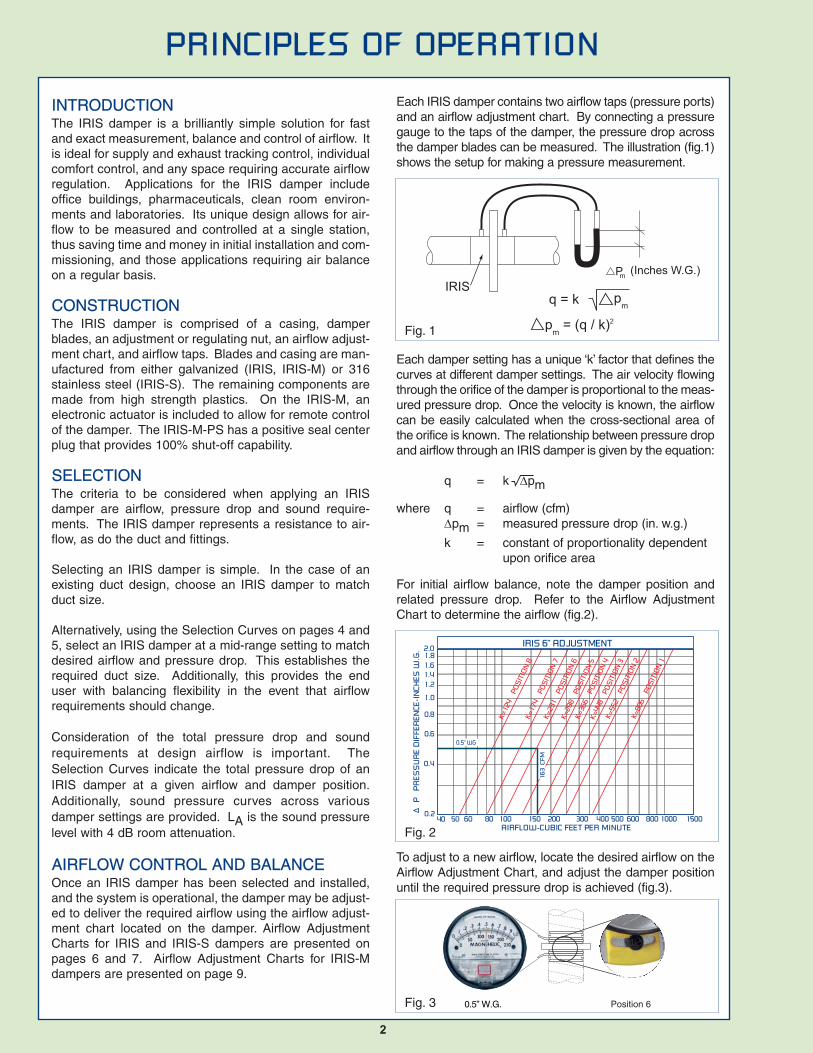
Each IRIS damper contains two airflow taps (pressure ports)and an airflow adjustment chart. By connecting a pressuregauge to the taps of the damper, the pressure drop acrossthe damper blades can be measured. The illustration (fig.1)shows the setup for making a pressure measurement.
Each damper setting has a unique ‘k’ factor that defines thecurves at different damper settings. The air velocity flowingthrough the orifice of the damper is proportional to the meas-ured pressure drop. Once the velocity is known, the airflowcan be easily calculated when the cross-sectional area ofthe orifice is known. The relationship between pressure dropand airflow through an IRIS damper is given by the equation:
q = k ∆pm
where q = airflow (cfm)∆pm = measured pressure drop (in. w.g.)
k = constant of proportionality dependent upon orifice area
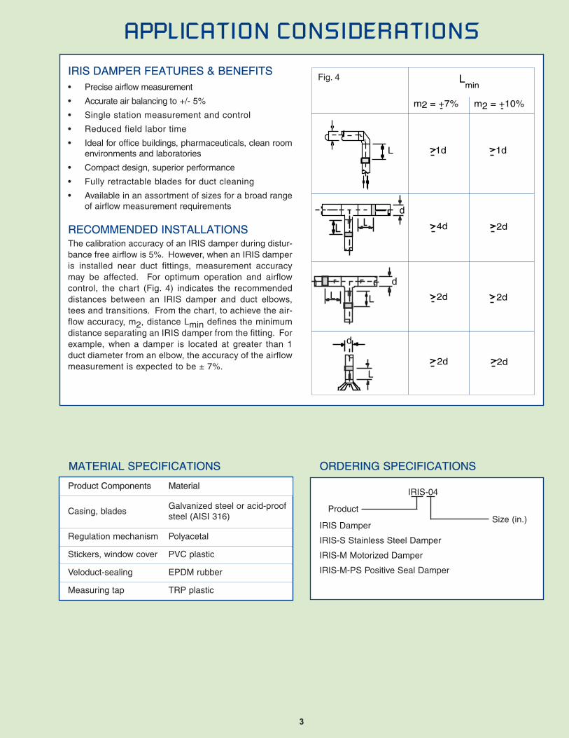
For initial airflow balance, note the damper position andrelated pressure drop. Refer to the Airflow AdjustmentChart to determine the airflow (fig.2).
To adjust to a new airflow, locate the desired airflow on theAirflow Adjustment Chart, and adjust the damper positionuntil the required pressure drop is achieved (fig.3).
Pm (Inches W.G.)
q = k
pm = (q / k)2
pm
IRIS
0.5” W.G. Position 6
0.5” WG
16
3 C
FM
IRIS 6” ADJUSTMENT
AIRFLOW-CUBIC FEET PER MINUTE
P P
RES
SU
RE
DIF
FER
ENCE
-IN
CHES
W.G
. 2.0
K=12
4
POS
ITIO
N 8
K=
174
PO
SIT
ION
7
K=23
1
POS
ITIO
N 6
K=29
8
POS
ITIO
N 5
K=36
6
POS
ITIO
N 4
K=44
8
POS
ITIO
N 3
K=55
2
POS
ITIO
N 2
K=
806
PO
SIT
ION
1 1.8
1.61.41.2
1.0
0.8
0.6
0.4
0.240 50 60 80 100 150 200 300 400 500 600 800 1000 1500
Fig. 1
Fig. 2
Fig. 3
3
APPLICATION CONSIDERATIONS
IRIS DAMPER FEATURES & BENEFITS• Precise airflow measurement
• Accurate air balancing to +/- 5%
• Single station measurement and control
• Reduced field labor time
• Ideal for office buildings, pharmaceuticals, clean roomenvironments and laboratories
• Compact design, superior performance
• Fully retractable blades for duct cleaning
• Available in an assortment of sizes for a broad rangeof airflow measurement requirements
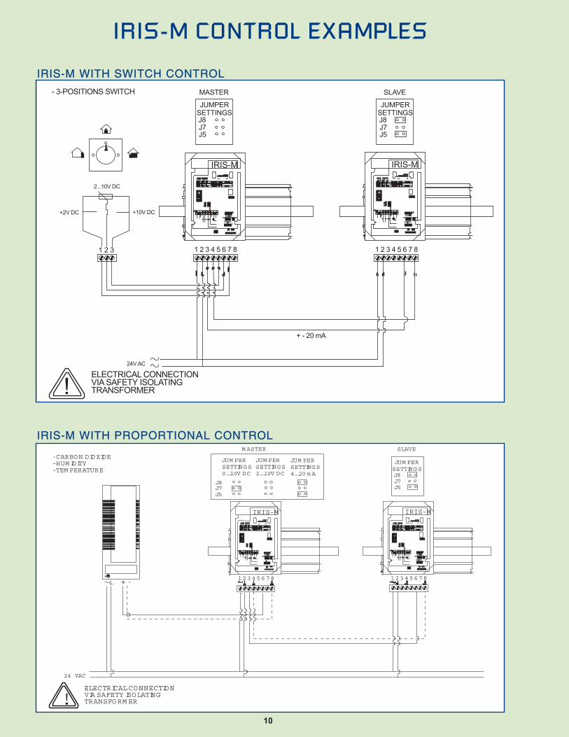
RECOMMENDED INSTALLATIONSThe calibration accuracy of an IRIS damper during distur-bance free airflow is 5%. However, when an IRIS damperis installed near duct fittings, measurement accuracymay be affected. For optimum operation and airflowcontrol, the chart (Fig. 4) indicates the recommendeddistances between an IRIS damper and duct elbows,tees and transitions. From the chart, to achieve the air-flow accuracy, m2, distance Lmin defines the minimumdistance separating an IRIS damper from the fitting. Forexample, when a damper is located at greater than 1duct diameter from an elbow, the accuracy of the airflowmeasurement is expected to be ± 7%.
Product Components Material
Casing, bladesGalvanized steel or acid-proofsteel (AISI 316)
Regulation mechanism Polyacetal
Stickers, window cover PVC plastic
Veloduct-sealing EPDM rubber
Measuring tap TRP plastic
MATERIAL SPECIFICATIONS ORDERING SPECIFICATIONS
IRIS-04
Product
IRIS Damper
IRIS-S Stainless Steel Damper
IRIS-M Motorized Damper
IRIS-M-PS Positive Seal Damper
Lmin
m2 = +7% m2 = +10%- -
1d 1d
4d 2d
2d 2d
2d 2d
L
d
d
L L
L
d
Size (in.)
Fig. 4

2.00
1.00
0.50
0.20
0.10
0.05
0.02160 200 500 1000 2000 250
q, cfm
Pt.
in
W
G
12” Damper Selection Curve
55
6 54
3
2
1
78
dB (A)
L A.
2.00
1.00
0.50
0.20
0.10
0.05
0.02500 1000 2000100 200
q, cfm
Pt. in WG
10 Damper Selection Curve
60
55
50
6 5
4
3
2
1
78
dB (A)
L A.
2.00
1.00
0.50
0.20
0.10
0.05
0.026 10 20 50 100 200 250
q, cfm
Pt. in WG
4 Damper Selection Curve
45
40
356 5 4 3 2 17
s = 8
dB (A)
L A.
2.00
1.00
0.50
0.20
0.10
0.05
0.0230 50 100 200 400
q, cfm
Pt. in WG
5 Damper Selection Curve
45
40
35
6 5 4 3
2
1
7
50
30
25
dB (A)
L A.
2.00
1.00
0.50
0.20
0.10
0.05
0.0250050 100 200 700
q, cfm
Pt. in WG
6 Damper Selection Curve
45
40
50
6 5
4
3
2
1
78
dB (A)
L A.
2.00
1.00
0.50
0.20
0.10
0.05
0.02100070 2000100 200 500
q, cfm
Pt. in WG
8 Damper Selection Curve
45
40
50
6 5 4
3
2
1
78
dB (A)
L A.
SELECTION CURVES
4

SELECTION CURVES
1.50
1.00
0.50
0.20
0.10
.015
0.02
2000500 1000200 2500q, cfm
Pt.
in
W
G16” Damper Selection Curve
25
30
35
6 5
4
3
2
1
7
s = 8
dB (A)
L A.
2.00
1.00
0.50
0.20
0.10
0.05
0.02300 1000 2000500 90005000
q, cfm
Pt.
in
W
G
20” Damper Selection Curve
45
40
55
6 5 4
3
2
1
7
s =
8
50
dB (A
)
L A.
2.00
1.00
0.50
0.20
0.10
0.05
0.021000 2000500 5000 10000 14000
q, cfm
Pt.
in
W
G
25” Damper Selection Curve
60
6
5 4 3 2 1
7
s =
8
dB (A
)
L A.
2.00
1.00
0.50
0.20
0.10
0.05
0.021000 2000 5000 10000500 16000
q, cfm
Pt.
in
W
G
32” Damper Selection Curve
45
40
356 5 4 3 2 17
s =
8
50
55
60
dB (A
)
L A.
5

Damper position2.00
1.50
1.00
0.50
0.30
0.20
0.10
0.050.04
0.40
0.03
0.0210 15 20 30 40 50 60 80 100 150 200 250
q, cfm
1
2
345678
K=34
8K=
251K=
201
K=15
1
K=11
4
K=84
K=57
K=30
4” Damper Adjustment Chart
P mIN
. WG
q, cfm
2.004567
K=157
K=117
5 Damper Adjustment CharDamper position
P mIN. WG
K=217
K=90
K=294
K=462
32
1
1.50
1.00
0.500.40
0.30
0.20
0.10
0.050.04
0.03
0.0220 30 40 50 70 100 150 200 300 400
K=50
q, cfm
2.004567
K=298
K=231
6 Damper Adjustment CharDamper position
P mIN. WG
K=368
K=174
K=448
K=806
3
2
1
1.50
1.00
0.500.40
0.30
0.20
0.10
0.050.04
0.03
0.0270030 40 50 70 100 500200 300 400
K=124
8
K=552
q, cfm
2.004567
K=609
K=468
8 Damper Adjustment CharDamper position
P mIN. WG
K=776
K=368
K=167
K=1478
3 2
11.00
1.50
0.500.40
0.30
0.20
0.10
0.05
0.04
0.03
0.02700150 100050 70 100 500200 300 400
K=281
8
K=1033
1500
6
MODEL A C D L OD WT(lbs)
IRIS-04, IRIS-S-04 1.2 0.6 3.9 4.6 6.5 1.1IRIS-05, IRIS-S-05 1.2 0.6 4.9 4.6 7.4 1.5IRIS-06, IRIS-S-06 1.2 0.6 5.9 4.6 9.1 2.0IRIS-08, IRIS-S-08 1.2 0.6 7.8 4.6 11.2 3.1IRIS-10, IRIS-S-10 1.6 0.7 9.8 5.3 13.2 4.6IRIS-12, IRIS-S-12 1.6 0.7 11.8 6.1 16.1 7.7IRIS-16, IRIS-S-16 2.4 0.8 15.7 7.5 20.7 14.1IRIS-20, IRIS-S-20 2.0 0.8 19.6 6.7 25.8 21.2IRIS-25, IRIS-S-25 2.0 0.9 24.7 6.7 32.1 34.4IRIS-32, IRIS-S-32 3.9 0.9 31.4 10.6 40.0 55.1
DIMENSIONS IN INCHES
D
A C A
L OD
IRIS-S STAINLESS STEEL DAMPER• AISI 316 stainless steel construction
• Prolonged excellence in extreme conditions
• Ideal for corrosive environments
• Capacities: 15 cfm to 20,000 cfm
IRIS DAMPER• Single station measurement and control
• Hot dipped galvanized steel construction
• Fitted neoprene gasket for airtight mounting
• Capacities: 15 cfm to 20,000 cfm
IRIS & IRIS-S DAMPERS
IRIS & IRIS-S DIMENSIONS

7
q, cfm
2.004567
K=22
51
K=17
63
16” Damper Adjustment ChartDamper position
P mIN
. WG
K=29
53K=12
88
K=51
8
K=43
81
3 2
11.50
1.00
0.500.40
0.30
0.20
0.10
0.050.04
0.03
0.02400030001000150 2000500200 300 400
K=95
0
8
K=34
11
5000q, cfm
2.004567
K=3746
K=2960
20 Damper Adjustment ChartDamper position
P mIN. WG
K=4883
K=2227
K=1003
K=7693
32
1
1.50
1.00
0.500.40
0.30
0.20
0.10
0.050.04
0.03
0.02700 5000300 400500 40001000 2000 3000
K=1605
8
K=5920
8000
q, cfm
2.004567
K=5652
K=4248
25 Damper Adjustment ChartDamper position
P mIN. WG
K=7960
K=3064
K=1174
K=15084
3 2
1
1.50
1.00
0.50
0.40
0.30
0.20
0.10
0.05
0.04
0.03
0.0210000400 600 1000 50002000 3000
K=2100
8
K=9933
16000q, cfm
2.004567
K=7258
K=5686
32 Damper Adjustment ChartDamper position
P mIN. WG
K=8930
K=13445K=2465
K=16355
3
2
1
1.50
1.00
0.500.40
0.30
0.20
0.10
0.050.04
0.03
0.022000 10000700 1000 1500 500030004000
K=4080
8
K=11505
15000
IRIS & IRIS-S DAMPERS
q, cfm
2.004567
K=1254
K=1013
12 Damper Adjustment ChaDamper position
P mIN. WG
K=1559
K=739K=
518
K=2579
3
2
1.50
1.00
0.500.40
0.30
0.20
0.10
0.05
0.04
0.03
0.02700 1000150 500200 300 400
8
K=2100
1500 2000 2500q, cfm
2.004567
K=1027
K=806
10 Damper Adjustment CharDamper position
P mIN. WG
K=1294
K=615
K=298
K=2154
3
2
1
1.00
1.50
0.500.40
0.30
0.20
0.10
0.050.04
0.03
0.02700150 1000250100 500200 300 400
K=428
8
K=1525
1500

8
DESCRIPTIONThe IRIS-M motorized damper assembly provides all thebenefits of the standard IRIS damper, plus adds anelectronic actuator to allow for remote control of thedamper. The IRIS-M is available in six sizes, and permitsthe damper to be controlled by a building control system,or operate as a standalone unit through the use of switch-es.
CONTROL FEATURES• Accepts 0-10 VDC, 2-10 VDC or 4-20 mA analog
inputs• Adjustable min/max pots for airflow settings• 2 position or modulating control• Fully open switch for duct cleaning• Airflow taps for measuring airflow with either manual
gauge or differential pressure transducer• Multiple actuators may be used in a master/slave
arrangement
ELECTRICAL/CONTROL SPECIFICATION• 24 VAC Supply Voltage• Rated Power - 4.5 VA• Inputs
0-10 VDC2-10 VDC4-20 mA
• Actuator Drive Time: 1-3 min.
IRIS-M & IRIS-M-PS DAMPERS
IRIS-MMOTORIZED DAMPER• Retracts fully for duct cleaning
• Finger tip control with adjustable set-points
• Interlocking galvanized steel plate construction
• Automatic measurement and control of airflow
• Accepts 0-10 VDC, 2-10 VOC or 4-20 mA signal
• Capacities: 15 cfm to 4,000 cfm
A, B 24 VAC power and input wiring connections
C, D Input jumpers and instructions
E Power on/off indicator
F Min/max flow indicators
G,H Min/max flow pots
I Drive open switch
IRIS-M WIRING CONNECTIONS
IRIS-M24V~50...60Hz4,5W
1 2 3 4 5 6 7 8J3
J7J8
J5
24V AC
4...20mA2V DC
ref.
OPERATIONPOSITION
CLEANINGPOSITION10V DC
SWITCHUNDERCOVER
2...10VDC0...10VDC4...20mA
POWER
JUMPER SETTINGS
qv max
qv min
J7 J8J5J3-6
J3-6J3-6
2...10VDC0...10VDC4...20mA
DEFAULT
SLAVE
- qv +
BA
C
GH
D
F
E
I
MODEL A C D E F L OD WT(lbs)
IRIS-M-04, IRIS-M-PS-04 1.2 0.6 3.9 6.1 1.7 4.6 6.5 4.4IRIS-M-05 1.2 0.6 4.9 6.6 1.7 4.6 7.4 4.8IRIS-M-06, IRIS-M-PS-04 1.2 0.6 5.9 7.5 1.6 4.6 9.1 5.3IRIS-M-08, IRIS-M-PS-04 1.2 0.6 7.8 8.5 1.6 4.6 11.2 6.4IRIS-M-10, IRIS-M-PS-04 1.6 0.7 9.8 9.4 1.3 5.3 13.2 7.9IRIS-M-12, IRIS-M-PS-04 1.6 0.7 11.8 10.5 1.0 5.6 16.1 11.0
DIMENSIONS IN INCHES
IRIS-M & IRIS-M-PS DIMENSIONS
IRIS-M-PSPOSITIVE SEAL DAMPER• Simple to calibrate min and max settings
• Positive seal with 100% shut-off capability
• Automatic measurement and control of airflow
• Finger tip control with adjustable set-points
• Interlocking galvanized steel plate construction
• Capacities: 15 cfm to 4,000 cfm
For IRIS-M-PS weight, add 0.5 lbs to IRIS-M.

9
2.00
1.50
1.00
0.500.400.30
0.20
0.10
0.050.040.03
0.0210 15 20 30 40 50 60 80 100 150 200 250
q, cfm
1
2
345678
K=34
8K=
251
K=20
1K=
151
K=11
4K=
84
K=57
K=30
4” Damper Adjustment ChartP m
IN. W
G8.5
5
K=13
.4
Min.2.00
1.50
1.00
0.500.40
0.30
0.20
0.10
0.050.04
0.03
0.0210 20 30 40 50 70 400100 150 200 300
q, cfm
1
2345678
K=462
K=294K=217
K=157
K=117K=90
K=50
5 Damper Adjustment Chart
P mIN. WG
K=23.4
Min.
K=16.7
2.00
1.50
1.00
0.500.40
0.30
0.20
0.10
0.050.04
0.03
0.027020 30 40 50 300 400100 500200 700
q, cfm
1
2
345678
K=552
K=448K=368
K=298 K=231
K=174
K=124
K=97
6 Damper Adjustment Ch
P mIN. WG
8.5
K=80.3
Min.
K=806
2.00
1.50
1.00
0.500.40
0.30
0.20
0.10
0.050.04
0.03
0.0270 1500100030 40 50 700100 150 200 300
q, cfm
1
2345678
K=1478K=
1033
K=776K=609
K=468
K=368
K=167
K=100.3
8 Damper Adjustment Ch
P mIN. WG
8.5
500
K=36.8
Min.
K=281
2.00
1.50
1.00
0.500.40
0.30
0.20
0.10
0.050.04
0.03
0.02100 150 300400 500 700 10001500200250
q, cfm
1
2
3
45678
K=2154
K=1525
K=1294
K=1027
K=806
K=615
K=428
K=298
10 Damper Adjustment Char
P mIN. WG
8.5
50
K=13.4
Min.
K=204
2.00
1.50
1.00
0.500.40
0.30
0.20
0.10
0.050.04
0.03
0.02150 200 300 400 500 700 1000 1500 20002500
q, cfm
2
3
45678
K=2579
K=2100
K=1559
K=1254
K=1013
K=739
K=518
12 Damper Adjustment Char
P mIN. WG
100
K=340
Min.
IRIS-M DAMPERS
10
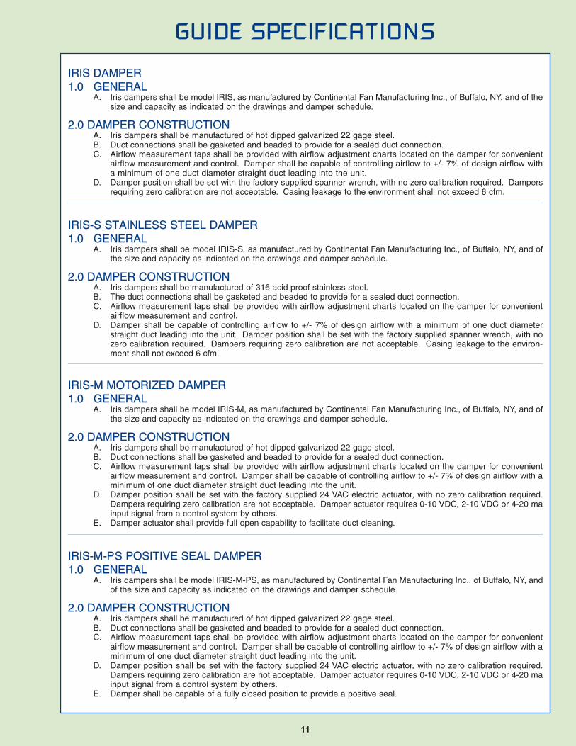
IRIS-M CONTROL EXAMPLES
+-
IRIS-M
+-
IRIS-M
JUMPERSETTINGSJ8J7J5
MASTER
JUMPERSETTINGSJ8J7J5
SLAVE
1 2 3 1 2 3 4 5 6 7 8 1 2 3 4 5 6 7 8
24V AC
ELECTRICAL CONNECTIONVIA SAFETY ISOLATINGTRANSFORMER!
- 3-POSITIONS SWITCH
+2V DC +10V DC
2...10V DC
+ - 20 mA
+-
IRIS-M
+-
IRIS-M
1 2 3 4 5 6 7 8 1 2 3 4 5 6 7 8+ -
+
24 VAC
ELECTRICAL CONNECTIONVIA SAFETY ISOLATINGTRANSFORM ER!
JUM PERSETTINGS0...10V DC
J8J7J5
M ASTER
JUM PERSETTINGSJ8J7J5
SLAVE
JUM PERSETTINGS2...10V DC
JUM PERSETTINGS4...20 m A
- CARBON DIOXIDE- HUM IDITY- TEM PERATURE
IRIS-M WITH SWITCH CONTROL
IRIS-M WITH PROPORTIONAL CONTROL
11
GUIDE SPECIFICATIONS
IRIS DAMPER1.0 GENERAL
A. Iris dampers shall be model IRIS, as manufactured by Continental Fan Manufacturing Inc., of Buffalo, NY, and of thesize and capacity as indicated on the drawings and damper schedule.
2.0 DAMPER CONSTRUCTIONA. Iris dampers shall be manufactured of hot dipped galvanized 22 gage steel.B. Duct connections shall be gasketed and beaded to provide for a sealed duct connection.C. Airflow measurement taps shall be provided with airflow adjustment charts located on the damper for convenient
airflow measurement and control. Damper shall be capable of controlling airflow to +/- 7% of design airflow witha minimum of one duct diameter straight duct leading into the unit.
D. Damper position shall be set with the factory supplied spanner wrench, with no zero calibration required. Dampersrequiring zero calibration are not acceptable. Casing leakage to the environment shall not exceed 6 cfm.
IRIS-S STAINLESS STEEL DAMPER1.0 GENERAL
A. Iris dampers shall be model IRIS-S, as manufactured by Continental Fan Manufacturing Inc., of Buffalo, NY, and ofthe size and capacity as indicated on the drawings and damper schedule.
2.0 DAMPER CONSTRUCTIONA. Iris dampers shall be manufactured of 316 acid proof stainless steel.B. The duct connections shall be gasketed and beaded to provide for a sealed duct connection.C. Airflow measurement taps shall be provided with airflow adjustment charts located on the damper for convenient
airflow measurement and control.D. Damper shall be capable of controlling airflow to +/- 7% of design airflow with a minimum of one duct diameter
straight duct leading into the unit. Damper position shall be set with the factory supplied spanner wrench, with nozero calibration required. Dampers requiring zero calibration are not acceptable. Casing leakage to the environ-ment shall not exceed 6 cfm.
IRIS-M MOTORIZED DAMPER1.0 GENERAL
A. Iris dampers shall be model IRIS-M, as manufactured by Continental Fan Manufacturing Inc., of Buffalo, NY, and ofthe size and capacity as indicated on the drawings and damper schedule.
2.0 DAMPER CONSTRUCTIONA. Iris dampers shall be manufactured of hot dipped galvanized 22 gage steel.B. Duct connections shall be gasketed and beaded to provide for a sealed duct connection.C. Airflow measurement taps shall be provided with airflow adjustment charts located on the damper for convenient
airflow measurement and control. Damper shall be capable of controlling airflow to +/- 7% of design airflow with aminimum of one duct diameter straight duct leading into the unit.
D. Damper position shall be set with the factory supplied 24 VAC electric actuator, with no zero calibration required.Dampers requiring zero calibration are not acceptable. Damper actuator requires 0-10 VDC, 2-10 VDC or 4-20 mainput signal from a control system by others.
E. Damper actuator shall provide full open capability to facilitate duct cleaning.
IRIS-M-PS POSITIVE SEAL DAMPER1.0 GENERAL
A. Iris dampers shall be model IRIS-M-PS, as manufactured by Continental Fan Manufacturing Inc., of Buffalo, NY, andof the size and capacity as indicated on the drawings and damper schedule.
2.0 DAMPER CONSTRUCTIONA. Iris dampers shall be manufactured of hot dipped galvanized 22 gage steel.B. Duct connections shall be gasketed and beaded to provide for a sealed duct connection.C. Airflow measurement taps shall be provided with airflow adjustment charts located on the damper for convenient
airflow measurement and control. Damper shall be capable of controlling airflow to +/- 7% of design airflow with aminimum of one duct diameter straight duct leading into the unit.
D. Damper position shall be set with the factory supplied 24 VAC electric actuator, with no zero calibration required.Dampers requiring zero calibration are not acceptable. Damper actuator requires 0-10 VDC, 2-10 VDC or 4-20 mainput signal from a control system by others.
E. Damper shall be capable of a fully closed position to provide a positive seal.

Wholesale Products DivisionWholesale Products DivisionThe Wholesale Products Division offers a superior line of commercial blowers, residential ventilation products and airpurification systems, available through a wide network of wholesalers and distributors throughout North America.
OEM Fan DivisionOEM Fan DivisionContinental Fan’s sales team provides customer focusedsolutions for original equipment manufacturers, by working closely with them during the design process, to find the bestproducts for their applications.
Industrial Fan DivisionIndustrial Fan DivisionContinental Fan’s Industrial Fan Division offers a superblycrafted collection of industrial ventilation products,uniquely marketed through a network of manufacturersrepresentatives across North America.
IRIS DAMPERS APPLICATION GUIDE
IRIS
-APP
LICA
TION
GUI
DE-0
705