ir reflectance of aircraft paints - dtic · standard form 298 (rev. 8/98) prescribed by ansi std....
TRANSCRIPT
PL-TR-94-2313
IR Reflectance of Aircraft Paints
Brian P. Sandford
2 December 1985
PHII.LIPS LABORATORY Directorate of Geophysics AIR FORCE MATERIEL COMMAND HANSCOM AIR FORCE BASE, MA 01731-3010

REPORT DOCUMENTATION PAGEForm Approved
OMB No. 0704-01-0188
The public reporting burden for this collection of information is estimated to average 1 hour per response, including the time for reviewing instructions, searching existing data sources,gathering and maintaining the data needed, and completing and reviewing the collection of information. Send comments regarding this burden estimate or any other aspect of this collectionof information, including suggestions for reducing the burden to Department of Defense, Washington Headquarters Services Directorate for Information Operations and Reports(0704-0188), 1215 Jefferson Davis Highway, Suite 1204, Arlington VA 22202-4302. Respondents should be aware that notwithstanding any other provision of law, no person shall be
PLEASE DO NOT RETURN YOUR FORM TO THE ABOVE ADDRESS.1. REPORT DATE (DD-MM-YYYY) 2. REPORT TYPE 3. DATES COVERED (From - To)
4. TITLE AND SUBTITLE 5a. CONTRACT NUMBER
5b. GRANT NUMBER
5c. PROGRAM ELEMENT NUMBER
5d. PROJECT NUMBER
5e. TASK NUMBER
5f. WORK UNIT NUMBER
6. AUTHORS
7. PERFORMING ORGANIZATION NAME(S) AND ADDRESS(ES) 8. PERFORMING ORGANIZATION REPORT NUMBER
10. SPONSOR/MONITOR’S ACRONYM(S)
11. SPONSOR/MONITOR’S REPORT NUMBER(S)
9. SPONSORING/MONITORING AGENCY NAME(S) AND ADDRESS(ES)
12. DISTRIBUTION/AVAILABILITY STATEMENT
13. SUPPLEMENTARY NOTES
14. ABSTRACT
15. SUBJECT TERMS
16. SECURITY CLASSIFICATION OF:
a. REPORT b. ABSTRACT c. THIS PAGE
17. LIMITATION OF ABSTRACT
18. NUMBER OF PAGES
19a. NAME OF RESPONSIBLE PERSON
19B. TELEPHONE NUMBER (Include area code)
Standard Form 298 (Rev. 8/98)Prescribed by ANSI Std. Z39.18
subject to any penalty for failing to comply with a collection of information if it does not display a currently valid OMB control number.
12-02-1985 Scientific, Final Infrared Reflectance of Aircraft Paints
62601F
Brian P. Sandford 3054
02
01
Phillips Laboratory 29 Randolph Road Hanscom AFB, MA 01731-3010
PL-TR-94-2313
Defense Advanced Research Projects Agency (STO) 1400 Wilson Blvd Arlington, VA 22209
PL/GPOA
Approved for Public Release; distribution unlimited.
.
Publicly Releasable Revision to AFGL-TR-84-0307
The reflectance and emittance properties of aircraft paints play an important role in determining IR contrast signatures. As an adjunct to its aircraft signature measurement program, the Geophysics Directorate of the Phillips Laboratory has also obtained paint chips from operational aircraft and had Surface Optics Corp. measure the paint directional and bidirectional reflectance properties. This report presents samples of these data and shows how they can be incorporated into aircraft signature calculations through of a semi-empirical bidirectional reflectance model. The model is incorporated into aircraft signature calculations through use of a semi-empirical bidirectional reflectance model. The model is incorporated into an IR signature code that calculates target thermal emissions plus specular and diffuse scatter of sunshine, earthshine, and skyshine.
Spectral directional reflectance Bidirectional reflectance
Brian P. Sandford
UNCL UNCL UNCL UNL 28

iii
Contents
1. INTRODUCTION 3
2. GENERAL REFLECTANCE PARAMETERS 4
3. PAINT REFLECTANCE DATABASE 8
3.1 Optical Properties 8
3.2 Paint Reflectance Data 13
4. ROBERTSON-SANDFORD REFLECTANCE MODEL 18
4.1 Model Assumptions and Properties 19
4.1 Diffuse Reflectance 20
4.3 Specular Reflectance 21
4.4 Shadowing and Obscuration 23
4.5 Comparison to SOC Data 23
5. CONCLUSIONS 27
6. REFERENCES 28
iv
Illustrations
1. Definition of the Angles (, ) 4
2. Angles for Scattering by a Surface Element 7
3. Logarithmic Polar Plot of the BRDF for Sample AFGL-01 15
4. The Spectral Directional Reflectance for Samples AFGL-03 and -09 15
5. The Directional Reflectance at I = 20° for Samples AFGL-03 and -09 16
6. Linear Polar Plots of the BRDF at i = 40° for Samples AFGL-03 and -09 16

INFRARED REFLECTANCE PROPERTIES OF AIRCRAFT PAINTS
12 February 1985 (Revised August 1994)
Brian P. Sandford Phillips Laboratory, Geophysics Directorate/GPOA
29 Randolph Road Hanscom AFB, MA 01731-3010
and
David C. Robertson Spectral Sciences, Inc. 99 S. Bedford Street
Burlington, MA 01803-5169
ABSTRACT
The reflectance and emittance properties of aircraft paints play an important role in determining IR contrast signatures. As an adjunct to its aircraft signature measurement program, the Geophysics Directorate of the Phillips Laboratory has also obtained paint chips from operational aircraft and had Surface Optics, Corp. measure the paint directional and bidirectional reflectance properties. This paper presents samples of these data and shows how they can be incorporated into aircraft signature calculations through use of a semi-empirical bidirectional reflectance model. The model is incorporated into an IR signature code that calculates target thermal emissions plus specular and diffuse scatter of sunshine, earthshine and skyshine.
APPROVED FOR PUBLIC RELEASE: ESC-94-1004, 26 Aug 94
1

2

1. INTRODUCTION
Analysis of elements contributing to aircraft signatures in the infrared (IR) has become of increasing
importance as IR detectors make rapid gains in efficiency and sensitivity. The increased sophistication
of air defense systems is forcing aircraft designers to pay careful attention to observable features
throughout the electromagnetic spectrum. Since the IR plays an important role for many present and
proposed systems, reflections and emissions from the airframe can lead to vulnerable situations if not
considered during their design.
Except for molecular emissions of the exhaust plume and emissions from hot metal parts related to
the engine, radiation emitted and scattered by the airframe is the dominant part of the aircraft IR
signature. The magnitudes of the airframe components are largely governed by the emissive-reflective
properties of the surface coatings, i.e., paints. This paper presents a discussion of the emissive-reflective
characteristics of paints from operational aircraft by describing a database developed by the Air Force
Phillips Laboratory, Geophysics Directorate (PL/GPOA) and a semi-empirical reflectance model
developed by Spectral Sciences, Inc. (SSI).
The airframe contrast signature in the IR consists of skin thermal emission plus reflection of sunshine,
skyshine, and earthshine. The intensities of these signature components can be characterized from the
directional and bidirectional reflectance of the surface. These are well defined optical surface properties
that can be measured in the laboratory and then incorporated into an aircraft signature computer code. The
next section presents the nomenclature for describing the optical properties of the surface. Section 3
presents illustrative examples of the database developed by PL/GPOA from measurements by Surface
Optics, Corp.(1-3) (SOC). Section 4 describes an emission-reflection model which derives its parameters
from the data and has been incorporated into SPIRITS and other aircraft signature codes.(4)
3

2. GENERAL REFLECTANCE PARAMETERS
The optical properties of a surface are completely defined by the bidirectional reflectance distribution
function (BRDF). The BRDF is defined as the surface reflectance for a given wavelength (λ), angles of
incidence (θi,φi) and angles of reflectance (θr,φr). The angles (θ,φ), shown in Figure 1, are the standard
zenith and polar angles measured from the z and x axes, respectively. Reflectance parameters used in
this paper are given in Table 1. This list is based on recent definitions that should be used in order
to standardize the nomenclature.(5,6) For an exhaustive discussion of this issue, the reader is directed to
Reference (6). The wavelength dependence of the BRDF is an important function that has been
suppressed in this treatment solely to simplify the notation.
When the surface shows no preferentially oriented marks (striae), the number of angles in the BRDF
may be reduced to three by defining the incident azimuth angle (φrr) relative to φi. The unit of
bidirectional reflectance is sr-1; it is defined as the ratio of the reflected intensity (W.sr-1) in direction
(θr,φr) to the incident energy in a collimated beam that illuminates the surface from direction (θi,φi).
Figure 1. Definition of the Angles (θ,φ).
4
Table 1. Nomenclature List for Various Reflectance Quantities.
SYMBOL DEFINITION UNITS
ρ,ρ(λ) (spectral) surface reflectance - ρ(λ,θ) directional spectral reflectance - ε,ε(λ) (spectral) surface emittance - ε(λ,θ) directional spectral emittance - α,α(λ) (spectral) surface absorptivity - α angle between glint vector and surface normal rad. A area m2
E irradiance (replaces H) W•m-2
fr,fr(θi,φi;θr,φr) BRDF s r -1
Bi-directional Reflectance Distribution Function fd,fs diffuse, specular part of the spectral BRDF - frI BRIDF s r -1
Bi-directional reflected intensity distribution function
I source radiant intensity (replaces J) W•sr-1
L radiance (replaces N) W•m-2•sr-1
Surfaces are frequently described as near diffuse (flat surface) or near specular (mirror surface). A
perfectly diffuse or lambertian surface reflects energy isotropically, i.e., the reflected energy measured
in any direction in the same for a given incident ray. Since the intercepted energy depends only on the
angle of incidence (θi) and the sample area, the BRDF is independent of (θr,φr). A 100 percent reflecting
and perfectly diffuse sample has, for all incident angles, a BRDF of 1/π sr-1 in all directions. A specular
surface reflects energy according to Snell's law, i.e., the incident beam is reflected with angle θr = θi and
φr = φi + 180°. A perfectly reflecting specular surface sends all the incident beam energy into the reflected
beam with no loss in intensity. If the incident beam were perfectly collimated (a physical impossibility),
the BRDF would be infinite at the reflected ray (θr,φr) and zero at all other angles (i.e., a delta-function).
Actual paint samples invariably exhibit features that are neither perfectly lambertain nor perfectly
specular.
When the BRDF is integrated over the hemisphere above the sample, the directional reflectance is
obtained. The directional reflectance (ρ) is only a function of the angles of incidence (θi,φi) and reduces
to a function of just θi when the surface is homogeneous with no preferential marks or surface scratches.
The integral relating directional and bidirectional reflectance is
5

Conservation of energy requires that radiation incident on a surface be either absorbed, transmitted
or reflected. This requires that
where α, τ, ρ are the absorptivity, transmittance, and reflectance. This is also true for the spectral
quantities. Excepting transparent surfaces like aircraft canopies, surfaces are opaque, and τ(λ) = 0.
Thus,
Note that Equations (2) and (3) are not always valid for each of the polarization components.(5)
Kirchhoff's law states that the absorptivity and emissivity of a blackbody in thermal equilibrium are
equal.(6) This is valid totally and spectrally,(5) i.e.,
This assumption relates the absorption of incident radiation at a given angle, (θi,φi), to the directional
emissivity at that angle.
2.1 Viewing Geometry.
Consider a planar surface element of area A. Its orientation in space is specified by the polar angles
(θ,φ) of its normal; θ is measured from the zenith, and φ is measured from the x-axis. The coordinate
axes are illustrated in Figure 1. The same coordinate system is used to specify the direction to the
observer (θr,φr) and to the sun (θi,φi). The unit vectors specifying the directions towards the observer
and illumination source are and , respectively. Thus, the directions of and are given by (θo s o s r,φr)
and (θi,φi), respectively.
Various angles for defining the scattering geometry are shown in Figure 2. For simplicity, the
surface normal lies along the z-axis. The unit vectors and s point towards the observer and source,
respectively. The glint vector is the unit vector for the bisector of the angle between and .
n o
g o s It is
given by
6
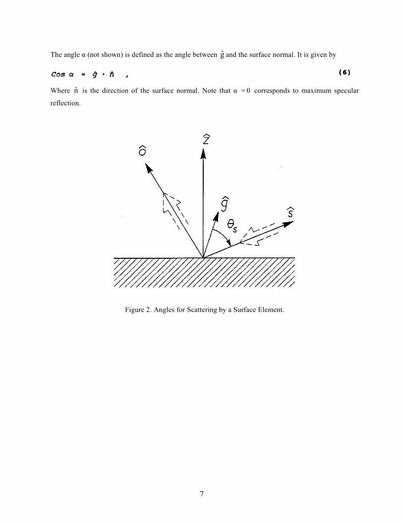
The angle α (not shown) is defined as the angle between and the surface normal. It is given by g
Where is the direction of the surface normal. Note that α = 0 corresponds to maximum specular
reflection.
n
Figure 2. Angles for Scattering by a Surface Element.
7
8
3. PAINT REFLECTANCE DATABASE
The PL Flying Infrared Signatures Technology Aircraft (FISTA) has been actively engaged in field
measurements (air-air) of aircraft IR signatures. Under many different programs PL/GPOA has supported
reduction and analyses of both target and background data. Application of these data to other scenario
conditions is made through the use of validated models. An important element is, of course, the
properties of airframe surface coatings or paints. The complex phenomenology of operational aircraft
finishes is strongly influenced by the spectral reflectance and bidirectional reflectance. Since a database
for reflectances of operational aircraft could not be found, PL/GPOA collected samples of panels from
various aircraft and contracted to Surface Optics Corporation (SOC), P.O. Box 261602, San Diego, CA
92196, the task of measuring paint reflectance properties. To date 50 (currently 102) samples have been
taken, mostly from operational aircraft, and 28 of these have been measured by SOC. Table 2 lists the
samples as of February 1985. Later measurements of spectral directional reflectance included the
perpendicular and parallel polarizations in addition to their sum. Approximate wavelengths for the BRDF
measurements are also given in the table.
3.1 Optical Properties
The measurement techniques used by SOC for the directional reflectance (ρ) and BRDF are described
elsewhere,(1-3) so we give only a brief description here. The directional reflectance, ρ(θi,φi), is a measure
of the ratio of the energy reflected into the hemisphere above the sample to the energy incident from a
given vector direction. The energy in the incident beam is divided into absorbed and reflected energy
without concern for where in the hemisphere the reflected energy goes. This means that a surface can
be specular or diffuse and still have the same directional reflectance. Directional reflectance data are
required for the determination of thermal emittance and solar absorptance, for thermal balance
calculations, and in the establishment of bidirectional reflectance in absolute terms. In many cases the
degree of surface specularity is important, and the BRDF is required to describe the distribution of the
reflected energy into the hemisphere above the sample. It must be measured over enough points in the
upper hemisphere to provide an adequate description of the reflected energy distribution. The number of
points depends on whether the surface exhibits a predominately diffuse or specular reflectance
characteristic. The BRDF is influenced not only by the composition of the surface material but also by
its condition and/or roughness.
9
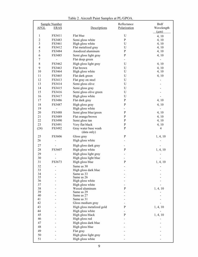
Table 2. Aircraft Paint Samples at PL/GPOA. Sample Number Reflectance Brdf
AFGL ERAS Descriptions
Polarization Wavelength (µm)
1 FS3411 Flat blue U 4, 10 2 FS3483 Semi gloss white P 4, 10 3 FS3461 High gloss white U 4, 10 4 FS3412 Flat metalized gray U 4, 10 5 FS3484 Anodized aluminum P 4, 10 6 FS3485 Semi gloss light gray P 4, 10 7 - Flat deep green - - 8 FS3462 High gloss light gray U 4, 10 9 FS3463 Flat brown U 4, 10
10 FS3464 High gloss white U 4, 10 11 FS3465 Flat dark green U 4, 10 12 FS3413 Flat gray on steel U - 13 FS3414 Semi gloss olive U - 14 FS3415 Semi gloss gray U - 15 FS3416 Semi gloss olive green U - 16 FS3417 High gloss white U - 17 FS3486 Flat dark gray P 4, 10 18 FS3487 High gloss gray P 4, 10 19 - High gloss white - - 20 FS3488 Semi gloss blue/green P 4, 10 21 FS3489 Flat orange/brown P 4, 10 22 FS3490 Semi gloss tan P 4, 10 23 FS3491 Very flat black P 4, 10 (24) FS3492 Gray water base wash
(data only) P 4
25 FS3606 Gloss gray P 1, 4, 10 26 - High gloss white - -
27 - High gloss dark gray - - 28 FS3607 High gloss white P 1, 4, 10 29 - High gloss light gray - - 30 - High gloss light blue - - 31 FS3673 High gloss blue P 1, 4, 10 32 - Same as 30 - - 33 - High gloss dark blue - - 34 - Same as 33 - -35 - Same as 26 - -36 - High gloss white - - 37 - High gloss white - - 38 - Waxed aluminum P 1, 4, 1039 - Same as 29 - -40 - Same as 27 - -
41 - Same as 31 - - 42 - Gloss medium gray - - 43 - High gloss metalized gold P 1, 4, 10 44 - High gloss white - - 45 - High gloss black P 1, 4, 10 46 - High gloss red - - 47 - High gloss dark blue - - 48 - High gloss blue - - 49 - Flat gray - - 50 - High gloss light gray - - 51 - High gloss white - -

3.1.1 SOC Integrating Sphere
In the wavelength range 0.3 to 2.0 µm, SOC utilizes an integrating sphere with a double beam
spectrophotometer to measure directional reflectance. The spectrophotometer provides a continuous
spectral directional reflectance output from 0.3 to 2.0 µm. Directional reflectance can also be directly
determined at discrete wavelengths by setting the dispersing elements at the desired wavelength. The
source is a 200 W (3400 K) lamp and a 150 W xenon lamp that has a continuous output over the
desired spectral range. A photodetector is used for 0.3 to 0.6 µm and a PbS detector from 0.6 to 2.0 µm.
The internal surface of the nine inch diameter integrating sphere is coated with a thick layer of
magnesium oxide. The sample, located at the center of the sphere, and the hemisphere behind it are
uniformly illuminated. The instrument utilizes a two beam system; one beam looks at the surface of the
sample and the other, the reference or 100 percent beam, looks at the wall of the integrating sphere. The
instrument automatically computes and records the ratio of the power incident on the sample surface from
the hemispherical uniform source to that reflected in the direction of the receiver (the spectrophotometer).
This ratio is the directional reflectance of the sample. The angle at which the directional reflectance is
measured is varied by rotating the sample.
Some limitations of the instrument are:
1. Reflections from normal incidence do not include the specular component. Measurements of the directional reflectance at normal incidence with this type of instrument are usually made to determine the ratio of the specular to diffuse components of the reflectance by comparing to a near normal (22°) measurement that has both components.
2. Measurements at “near normal” incidence are limited to an angle of about 20° from the normal.
3. Measurements at “grazing” incidence are limited to an angle of about 80° from the normal. This limitation arises from two considerations. First the image of the spectrometer entrance slit projected to the sample surface falls off the finite sized sample as the sample becomes parallel to the direction of the receiver. Second, as grazing incidence is approached, due care must be taken to assure the energy is in fact not reflected from the edge of the sample.
3.1.2 SOC Ellipsoidal Reflectometer
Suitable materials are not available for integrating spheres over such a wide IR spectral range, so an
ellipsoidal reflectometer is used to measure the directional reflectance from 1.0 to 600 µm.(1,3) This
instrument utilizes a blackbody source, a grating spectrometer, filters for wavelength determination and
10
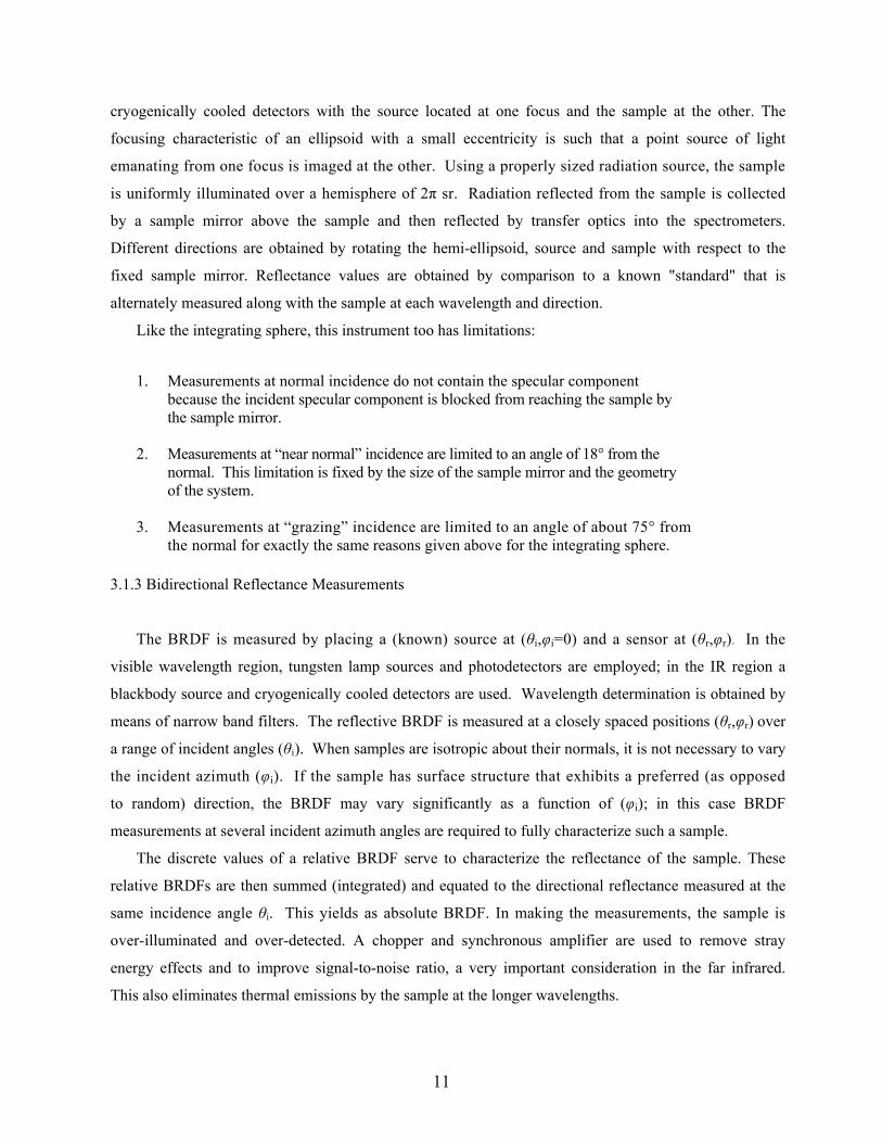
cryogenically cooled detectors with the source located at one focus and the sample at the other. The
focusing characteristic of an ellipsoid with a small eccentricity is such that a point source of light
emanating from one focus is imaged at the other. Using a properly sized radiation source, the sample
is uniformly illuminated over a hemisphere of 2π sr. Radiation reflected from the sample is collected
by a sample mirror above the sample and then reflected by transfer optics into the spectrometers.
Different directions are obtained by rotating the hemi-ellipsoid, source and sample with respect to the
fixed sample mirror. Reflectance values are obtained by comparison to a known "standard" that is
alternately measured along with the sample at each wavelength and direction.
Like the integrating sphere, this instrument too has limitations:
1. Measurements at normal incidence do not contain the specular component because the incident specular component is blocked from reaching the sample by the sample mirror.
2. Measurements at “near normal” incidence are limited to an angle of 18° from the normal. This limitation is fixed by the size of the sample mirror and the geometry of the system.
3. Measurements at “grazing” incidence are limited to an angle of about 75° from the normal for exactly the same reasons given above for the integrating sphere.
3.1.3 Bidirectional Reflectance Measurements
The BRDF is measured by placing a (known) source at (θi,φi=0) and a sensor at (θr,φr). In the
visible wavelength region, tungsten lamp sources and photodetectors are employed; in the IR region a
blackbody source and cryogenically cooled detectors are used. Wavelength determination is obtained by
means of narrow band filters. The reflective BRDF is measured at a closely spaced positions (θr,φr) over
a range of incident angles (θi). When samples are isotropic about their normals, it is not necessary to vary
the incident azimuth (φi). If the sample has surface structure that exhibits a preferred (as opposed
to random) direction, the BRDF may vary significantly as a function of (φi); in this case BRDF
measurements at several incident azimuth angles are required to fully characterize such a sample.
The discrete values of a relative BRDF serve to characterize the reflectance of the sample. These
relative BRDFs are then summed (integrated) and equated to the directional reflectance measured at the
same incidence angle θi. This yields as absolute BRDF. In making the measurements, the sample is
over-illuminated and over-detected. A chopper and synchronous amplifier are used to remove stray
energy effects and to improve signal-to-noise ratio, a very important consideration in the far infrared.
This also eliminates thermal emissions by the sample at the longer wavelengths.
11

Measurement limitations of this BRDF apparatus are:
1. True monostatic measurements cannot be made with this type of bidirectional reflectance apparatus. The source and detector cannot be brought into coincidence either mechanically or optically. In the visible and near IR spectrum, the detector-source included angle may be reduced to a minimum of about 15°. In the far IR, this angle is limited to a minimum of about 30° because of the physical size of the detector dewar.
2. BRDF measurements are limited to grazing angles of about 85°.
3. Very "black" samples, specular or diffuse, can yield noisy bidirectional reflectance data because the signal-to-noise ratio attainable with the apparatus is low.
4. The bidirectional reflectance in the grazing angles between 85° and 90° may include a significant portion of the reflected energy, which amount is difficult to estimate by extrapolation. The calibration of relative BRDF to absolute BRDF is done by normalizing to the directional reflectance; this can give rise to an error of up to 5 percent.
3.1.4 Sample Preparation
Skin samples were collected from operational aircraft, either from recently crashed aircraft or from small
inspection covers that could easily be replaced. The covers were checked to insure that their surface
finishes were typical of the finish and condition of that paint on the aircraft as a whole. In all cases, the
coatings have been subjected to normal operational conditions, that is, they have been exposed to weather,
repairs, retouching, cleaning, flying, and handling that arises during a typical lifetime in service.
The SOC equipment described above for directional reflectance and BRDF measurements utilized the
same size and type sample. This feature was purposely designed into the apparatus to assure that identical
samples may be used for both measurements. This is especially important for the BRDF since its
normalization requires use of the directional reflectance results. The samples are one inch flat discs that
were milled by PL/GPOA from the aircraft skin samples, with the outer rim under cut at a sharp angle to
minimize edge reflection.
Samples were measured “as received” and in a cleaned condition. Cleaning increased the reflectivity
by only a few percent at most. These samples were recleaned by gently scrubbing with an aircraft
cleaning detergent, thoroughly rinsing under running tap water, blotting off excess water with paper
towels and allowed to air dry. This process is similar to that used to clean aircraft under operational
conditions.
12
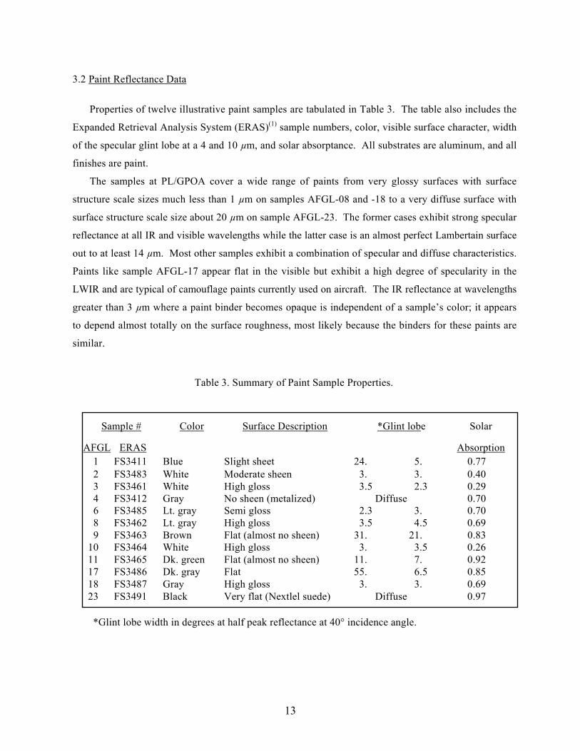
3.2 Paint Reflectance Data
Properties of twelve illustrative paint samples are tabulated in Table 3. The table also includes the
Expanded Retrieval Analysis System (ERAS)(1) sample numbers, color, visible surface character, width
of the specular glint lobe at a 4 and 10 µm, and solar absorptance. All substrates are aluminum, and all
finishes are paint.
The samples at PL/GPOA cover a wide range of paints from very glossy surfaces with surface
structure scale sizes much less than 1 µm on samples AFGL-08 and -18 to a very diffuse surface with
surface structure scale size about 20 µm on sample AFGL-23. The former cases exhibit strong specular
reflectance at all IR and visible wavelengths while the latter case is an almost perfect Lambertain surface
out to at least 14 µm. Most other samples exhibit a combination of specular and diffuse characteristics.
Paints like sample AFGL-17 appear flat in the visible but exhibit a high degree of specularity in the
LWIR and are typical of camouflage paints currently used on aircraft. The IR reflectance at wavelengths
greater than 3 µm where a paint binder becomes opaque is independent of a sample’s color; it appears
to depend almost totally on the surface roughness, most likely because the binders for these paints are
similar.
Table 3. Summary of Paint Sample Properties.
Sample # Color Surface Description *Glint lobe Solar
AFGL ERAS Absorption1 FS3411 Blue Slight sheet 24. 5. 0.77 2 FS3483 White Moderate sheen 3. 3. 0.40 3 FS3461 White High gloss 3.5 2.3 0.29 4 FS3412 Gray No sheen (metalized) Diffuse 0.70 6 FS3485 Lt. gray Semi gloss 2.3 3. 0.70 8 FS3462 Lt. gray High gloss 3.5 4.5 0.69 9 FS3463 Brown Flat (almost no sheen) 31. 21. 0.83
10 FS3464 White High gloss 3. 3.5 0.26 11 FS3465 Dk. green Flat (almost no sheen) 11. 7. 0.92 17 FS3486 Dk. gray Flat 55. 6.5 0.85 18 FS3487 Gray High gloss 3. 3. 0.69 23 FS3491 Black Very flat (Nextlel suede) Diffuse 0.97
*Glint lobe width in degrees at half peak reflectance at 40° incidence angle.
13
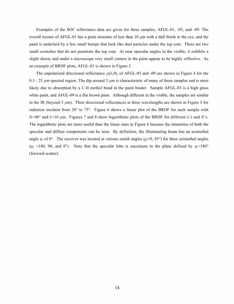
Examples of the SOC reflectance data are given for three samples, AFGL-01, -03, and -09. The
overall texture of AFGL-01 has a grain structure of less than 10 µm with a dull finish to the eye, and the
paint is underlaid by a few small bumps that look like dust particles under the top coat. There are two
small scratches that do not penetrate the top coat. At near specular angles in the visible, it exhibits a
slight sheen, and under a microscope very small centers in the paint appear to be highly reflective. As
an example of BRDF plots, AFGL-01 is shown in Figure 3.
The unpolarized directional reflectance, ρ(λ,θ), of AFGL-03 and -09 are shown in Figure 4 for the
0.3 - 25 µm spectral region. The dip around 3 µm is characteristic of many of these samples and is most
likely due to absorption by a C-II methyl bond in the paint binder. Sample AFGL-03 is a high gloss
white paint, and AFGL-09 is a flat brown paint. Although different in the visible, the samples are similar
in the IR (beyond 3 µm). Their directional reflectances at three wavelengths are shown in Figure 5 for
radiation incident from 20° to 75°. Figure 6 shows a linear plot of the BRDF for each sample with
θi=40° and λ=10 µm. Figures 7 and 8 show logarithmic plots of the BRDF for different λ’s and θi’s.
The logarithmic plots are more useful than the linear ones in Figure 6 because the intensities of both the
specular and diffuse components can be seen. By definition, the illuminating beam has an azimuthal
angle φi of 0°. The receiver was located at various zenith angles (ρr=0, 85°) for three azimuthal angles
(φr =180, 90, and 0°). Note that the specular lobe is maximum in the plane defined by φr=180°
(forward scatter).
14
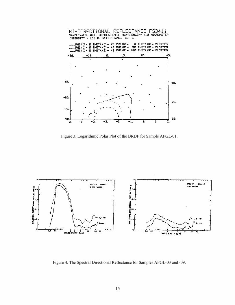
Figure 3. Logarithmic Polar Plot of the BRDF for Sample AFGL-01.
Figure 4. The Spectral Directional Reflectance for Samples AFGL-03 and -09.
15

Figure 5. The Directional Reflectance at θi =20° for Samples AFGL-03 and -09.
Figure 6. Linear Polar Plots of the BRDF at θi=40° for Samples AFGL-03 and -09
16

Figure 7. Logarithmic Polar Plots of the BRDF for Sample AFGL-03. (a) θi = 20º, λ = 10 μm, φ i = 0, 90 and 180º (c) θ i = 40º, λ = 10 μm, φ i = 0, 90 and 180º (b) θi = 20º, λ = 3.8 μm, φ i = 0, 90 and 180º (d) θ i = 40º, λ = 3.8 μm, φ i = 0, 90 and 180º
Figure 8. Polar Plots of the BRDF for Sample AFGL-09.
(a) θi = 20º, λ = 10 μm, φ i = 0, 90 and 180º (c) θ i = 40º, λ = 10 μm, φ i = 0, 90 and 180º (b) θi = 20º, λ = 3.8 μm, φ i = 0, 90 and 180º (d) θ i = 40º, λ = 3.8 μm, φ i = 0, 90 and 180º
17

4. ROBERTSON-SANDFORD REFLECTANCE MODEL
The Robertson-Sandford (R-S) directional reflectance model provides a consistent description of
surface emissive and reflectance properties in terms of a few semi-empirical parameters. Although this
discussion is based on opaque planar surfaces, the model is easily extended to transmitting surfaces, by
defining a spectral transmittance as part of the paint data file. Two key features of the model are a
semi-empirical formulation for the angular dependence of diffuse scatter and emission, and a finite width
to the angular distribution for specular scatter. The width of the specular lobe is based on a model for
surface roughness developed by Trowbridge and Reitz.(8)
The R-S model is empirical in that its emittance and reflectance parameters are derived from analysis
of reflectance data. Surface reflectance results from many underlying physical parameters and processes;
examples are the dielectric properties of the scattering surface (expressed as the complex index of
refraction), surface roughness effects, subsurface (or volume) scattering, thickness of a paint layer,
scattering from a substrate, and polarization effects.(1,5,8,10-12) In addition one has to consider the combined
effects of aging and weather for surfaces used on aircraft or other operational vehicles. The object of
this model is to arrive at a simplified parameterization of a paint’s reflectance properties that is suitable
for incorporation into a code for calculating target signatures. This includes scattered sunshine,
earthshine, and skyshine plus surface emissions.
The four basic parameters are:
ρD(λ) = diffuse spectral reflectance,
ε(λ) = spectral emissivity,
b = grazing angle reflectivity, and
e = width of specular lobe
The first two vary with wavelength; the second two are used to fit the angular distribution of the data.
The model is empirically based in that these emittance and reflectance parameters are derived from
analysis of reflectance data (e.g., those taken by SOC).
We make the physically reasonable assumption that b and e vary slowly with wavelength, so that they
can be treated as constant over finite wavelength regions. For the BRDF and related quantities,
18

where ρr (the BRDF) gives the angular dependence of the reflected radiation. Factorization is assumed
so that the spectral and angular properties vary independently.
4.1 Model Assumptions and Properties
4.1.1 Factorization of Angular and Spectral Dependencies
The angular dependence of the emissivity and the reflectivity is essentially wavelength
independent over fairly wide spectral regions.
4.1.2 Angular Dependence of Emissivity
The directional and spectral dependence of the emissivity is given by
where
By requiring ε(λ) to be the total hemispherical emittance of the surface element, G(b), the normalization
constant for the angular distribution, is given by
The cosine factor gives the effective area of the surface element. The constant b is empirical, is
determined from surface reflectance data, and takes the emissivity to zero as θr approaches 90°. A
Lambertain surface has b = 0. and emits equally in all directions.
19

4.1.3 Total Reflectance
Consider an incident, well collimated beam of light like that coming from the sun. From Equation (4)
the amount of energy in a wavelength interval absorbed by a surface equals the emissivity of the
surface. The reflected radiation is divided into diffuse and specular components, so that
where the subscripts identify the specular and diffuse contributions and the bar indicates integration over
all reflection directions (i.e., the total reflectance). Figure 9 shows the angular dependence of the total
reflectance predicted by Equation (11) for three illustrative values of b.
Figure 9. Angular Dependence of the Total Reflectance for Three Values of the Parameter b.
4.2 Diffuse Reflectance
Diffuse reflectance is assumed to be an average property of the surface resulting from subsurface
scattering and from multiple scattering due to surface roughness on the microscopic level. The amount
of radiation available for diffuse scattering varies with the angle of the incident beam. We assume that
20
the directional dependence from an illuminated surface is the same as its emissivity. We then assume that
the scattering process is symmetrical, e.g.,(6)
and that the diffuse BRDF is given by
The amount of diffusely scattered energy is given by ρd(λ)g(θi), and the angular distribution of that
radiation is given by g(θr). The diffusely scattered energy is given by
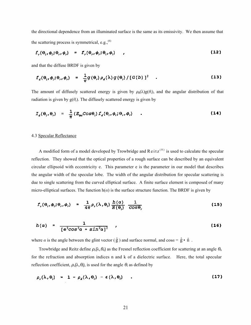
4.3 Specular Reflectance
A modified form of a model developed by Trowbridge and R e i t z ( 8 ) is used to calculate the specular
reflection. They showed that the optical properties of a rough surface can be described by an equivalent
circular ellipsoid with eccentricity e. This parameter e is the parameter in our model that describes
the angular width of the specular lobe. The width of the angular distribution for specular scattering is
due to single scattering from the curved elliptical surface. A finite surface element is composed of many
micro-elliptical surfaces. The function h(α) is the surface structure function. The BRDF is given by
where α is the angle between the glint vector ( ) and surface normal, and cosα = • . g g n
Trowbridge and Reitz define ρs(λ,θs) as the Fresnel reflection coefficient for scattering at an angle θs
for the refraction and absorption indices n and k of a dielectric surface. Here, the total specular
reflection coefficient, ρs(λ,θi), is used for the angle θi as defined by
21

Since ρs(θi) gives the fraction of the incident energy which undergoes specular reflection, it is required
that the integral of Equation (15) over all observer angles (θi,φr) be normalized to ρs. Thus,
The energy scattered specularly for given incident and exciting directions is
Maximum specular scatter occurs when α = 0.
An example of specular scattering for three different values of the parameter e is shown in Figure
10. The BRDF is calculated for an angle of 20° for the incident radiation and for a total reflectivity
(specular only) of 0.20.
Figure 10. The BRDF for Incident Radiation at 20° and for Three Values of the Parameter e.
22

4.4 Shadowing and Obscuration
As the observer angle θr approaches 90°, the predicted amount of specularly reflected energy remains
finite. This leads to divergences in the BRDF as θ approaches 90°. The data shown by Torrence and
Sparrow exhibit this divergence, but with a sharp cut-off at 90° so that there is a peak in the BRDF
around 85° (11) The divergence in the BRDF arises from the parameterization of the surface roughness
as a single equivalent curved surface (ellipsoidal) that scatters for all angles. Shadowing and obscuration
of scattering surface elements occur for grazing angles because the surface is planar in the macroscopic
sense; this causes a cut-off at 90°. Convenient cut-off factors are
and
Both factors lead to very messy normalization integrals when combined with the specular scattering
function, Equation (16). One way to get around this is to note that the cut-off is only significant in the
80-90° range and that Equation (16) is approximately constant except for incident angles near 90°.
Equation (21) is used in this model to cut-off the BRDF with δ = b and normalized to 1.0 at θ = 80°.
4.5 Comparison to SOC Data
Comparisons to reflectance data are presented for two samples, AFGL-01 (Camouflage Paint) at 4.0
µm and AFGL-10 (Gloss White Paint) at 3.0 µm. The model parameters used for each sample are given
in Table 4. Figure 11 shows a comparison of the BRDF for AFGL-01 at a wavelength of 3.8 µm and
at three angles of incidence (θi = 20, 40, 60°) for forward scatter, φr = 180°; this shows the glint lobe.
The angular dependencies of the total reflectance for AFGL-01 and AFGL-10 are shown in Figures 12
and 14, respectively. Similar comparisons of the BRDF for sample AFGL-10 are shown in Figure 13.
The model does a good job of following the trends in the angular dependence of the data. The sharper
specular features seen in Sample AFGL-10 (White Gloss Paint) result from a smaller value of e (see Table
4). The calculations for each sample were done with fixed values of the four parameters, b, e, εo, and
ρD, showing that this simple four-parameter model gives a good fit to the data.
23

Table 4. Parameters for Reflectance Model at 4µm.
Paint Sample ρ0 ε0 b eAFGL-01 (Camouflage) .07 .85 .12 .12 AFGL-10 (White Gloss) .05 .88 .08 .012
24

Figure 11. Comparison of Model Calculations (- - -) and SOC Data (──) at 4 µm
for sample AFGL-01 for Three BRDF (θi = 20, 40, 60°).
Figure 12. Model Calculations of the Total and Diffuse Reflectance and the SOC Reflectance Data at 4.0 µm for AFGL-01.
25
Figure 13. Comparison of Model Calculations (- - -) and SOC Data (──)
at 3.8 µm for sample AFGL-10 for BRDF (θi = 20, 40, 60°).
Figure 14. Model Calculations of the Total and Diffuse Reflectance and the SOC Data at 4.0 µm for Sample AFGL-10.
26

5 . CONCLUSIONS
As IR detection systems continue to become increasingly sophisticated, the reflectance properties of
airframe paints are one of many signature elements to which aircraft designers must become increasingly
sensitive. Our goal in this paper has been to make the research community aware of the reflectance (and
aircraft IR signature) data available at PL/GPOA and to introduce an approach for synthesizing these data
within the framework of an IR signature model. Further work to expand the data base, analyze the
reflectance data, and further validate the model is continuing (and support is welcome!).
27
6. REFERENCES
1. J. T. Neu and R. S. Dummer, “Theoretical and Practical Implication of the Bidirectional Reflectance of Spacecraft Surfaces”, AIAA Journal, 7, 484 (1969).
2. J. T. Neu, R. S. Dummer, and J. H. Wray, Private Communication to B. Sandford (1982).
3. J. T. Neu, R. S. Dummer, M. Beecroft, P. McKenna, and D. C. Robertson, “Surface Optical Property Measurements on Bark and Leaf Samples”, Phillips Laboratory Rpt. PL-TR-91-2009 (December 1990) ADA240714.
4. D. C. Robertson, “Aircraft Contrast Signatures in the Infrared Spectral Region”, SPIE, 327, 59 (1982).
5. W. L. Wolf and Zissis, eds., The Infrared Handbook, The IRIA Center, Environmental Research Institute of Michigan, P.O. Box 8618, Ann Arbor, MI (1978).
6. F. E. Nicodemus, J. C. Richmond, J. J. Hsia, I. W. Ginsberg, and T. Limperis, “Geometrical Considerations and Nomenclature for Reflectance”, U. S. Department of Commerce, National Bureau of Standards, Washington, DC, NBS Monograph 160 (1977).
7. F. E. Nicodemus, “Directional Reflectance and Emissivity of an Opaque Surface”, Appl. Opt., 4, 767 (1965).
8. T. S. Trowbridge and K. P. Reitz, “Average Irregularity of a Rough Surface for Ray Reflections”, J. Opt. Soc. Am., 65, 531 (1975).
9. D. Tanre, et al., “Atmospheric Modeling for Space Measurements of Ground Reflectances, Including Bidirectional Properties”, Appl. Opt., 18, 3587 (1979).
10. J. R. Aronson and A. E. Emslie, “Modeling the Infrared Emittance of Paints”, Report No. 83670-28, Arthur D. Little, Inc., Cambridge, MA 02140 (October 1980).
11. K. E. Torrance and E. M. Sparrow, “Theory for Off-Specular Reflection from Roughened Surfaces”, J. Opt. Soc. Am., 67, 1105 (1967).
12. J. C. Leader, “Analysis and Prediction of Laser Scattering from Rough-Surface Materials”, J. Opt. Soc. Am., 69, 610 (1979).
28