ir preheater - jbc soldering tools · ir preheater ir preheater ref. ph-1b (120v) ref. ph-2b (230v)...
TRANSCRIPT

日本語 26
Deutsch 18
Español 10
English 2
Page
IR PreheaterRef. PH-B
www.jbctools.com
中文 34

22
Packing List
The following items should be included:
Heater Unit
Heater Unit ................................................1 unit
Console. .....................................................1 unit
Power Cord ...............................................1 unit
Kapton Tape .............................................1 unit
Thermocouple ..........................................1 unit
Console
Power CordRef. 0009417 (100V/120V) Ref. 0009401 (230V)
ThermocoupleRef. PH218
Kapton TapeRef. PH217
Manual
www.jbctools.com
Ref. PH-BIR Preheater
IR PreheaterRef. PH-1B (120V)Ref. PH-2B (230V) Ref. PH-9B (100V)
2

33
Features
Console socket connection Pedal socket connection (optional)
Heating Area
Mains input
Mains switch
Fixing brackets for PH321 Support
Heater Unit
Console
Auxiliary Thermocouple (Type K) Input
Thermocouple (Type K)
USB-B connector to PC:- Update the Control Unit software
Zone B
Zone A
Control Unit
3
www.jbctools.com

44
Profiles by Temperature
Why Infrared? The most efficient technology for PCB preheating
Operation
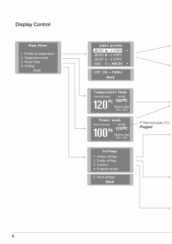
The usual way to run a profile is using the Thermocouple (TC) connected to the Control Input of the console. JBC offers 3 predefined profiles (JBCset) and 20 profiles ready for you to personalize.
JBCset profiles There are 3 profiles predefined by JBC: A, B and C. The difference between them is the number of steps: 2, 3 or 4. The thicker your PCB is and the more layers it contains, the more steps are needed to obtain a gradual warming. These profiles are not modifiable but they can be used as a template to create your own profiles.
JBCset A2 steps
JBCset B3 steps
JBCset C4 steps
This is the most advanced, efficient and cost-effective method to preheat PCBs in any soldering job or rework job. The low thermal mass of the infrared element gives outstanding control of the heat output and the process temperature. This technology provides fast response, high heating rates and uniform heating that ensure the best results.
For repetitive jobs we recommend running profiles without the Thermocouple (TC). Once any profile has been run to the end, the system has all the process data which you can save. Once it is saved, you can run this profile without connecting the Thermocouple (TC). The heating process will the same as long as the same working conditions are respected.
User profiles You can create your own profiles from the JBCset profiles. On the work screen of the profile, press the Enter button and choose the option Edit profile.
Power or Temperature ModesThe unit works at the selected power or temperature during the defined time. These parameters can be modified from the work screen by pressing the Enter button and the Edit parameters menu.To see the current temperature you must plug the Thermocouple (TC) into the Control connector.
PCB reference specifications:
FR4 1,6mm thick and 2 layers.
FR4 2,2mm thick and 6 layers.
FR4 1,6mm thick and 6 layers.
Profiles set using the low position of the PH321 PCB Support (28 mm in height between the PCB and the heating area).
4

55
Recommended Guidelines
1. Place the Thermocouple (TC) as near as possible to the component being worked on.
2. If there are any sensitive components, use the Auxiliary Thermocouple as protection.You can select the protection temperature in Station settings. If the selected temperature is rea-ched, the Heater Unit will stop the process and a warning message will be shown.
3. IPC* does not recommend exceeding ramp-up rates over 3 - 4 °C / sec (5 - 7 °F / sec) so as to reduce the risk of thermal stress on the PCB.* IPC was founded in the U.S. in 1957 as the Institute for Printed Circuits.
Fix the TC with Kapton Tape
Auxiliary Thermocouple (TC)
5
www.jbctools.com
66
Display Control
6

777
www.jbctools.com

88
Safety
It is imperative to follow safety guidelines to protect health and prevent electric
shock, injury, fire or explosions.
- Do not use the units for any purpose other than PCB preheating. Incorrect use may cause fire.
- The power cord must be plugged into approved bases. Be sure that it is properly grounded before use. When unplugging it, hold the plug, not the wire.
- The temperature of accessible surfaces may remain high after the unit is turned off. Handle with care.
- Do not leave the appliance unattended when it is on.
- Do not cover the ventilation grills. Heat can cause inflamable products to ignite. - Use a “non residue” classified flux and avoid contact with skin or eyes to prevent irritation. - Be careful with the fumes produced when soldering.
- Keep your workplace clean and tidy. Wear appropriate protective glasses and gloves when working to avoid personal harm.
- Utmost care must be taken with liquid tin waste which can cause burns.
- This appliance can be used by children over the age of eight and also persons with reduced physical, sensory or mental capabilities or lack of experience provided that they have been given adequate supervision or instruction concerning use of the appliance and understand the hazards involved. Children must not play with the appliance.
- Maintenance must not be carried out by children unless supervised.
8

99
Specifications
PH-1B 120V. Input 120V 50/60Hz Fuse 8APH-2B 230V. Input 230V 50/60Hz Fuse 4APH-9B 100V. Input 100V 50/60Hz Fuse 8A- Total weight: 2,8 kg (6.2 lb)- Dimensions Heater Unit: 173 x 282 x 41 mm- Maximum Power: 500VA- Heating Area: 65 x 135mm (1 zone) 30 x 135mm (2 zones)- Temperature Range: 50-250°C (120-482ºF)- Temperature Measurement: Thermocouple type K- JBCset temperature profiles: 3 profiles ( 2, 3 or 4 steps)- User Profiles: 20 (up to 6 steps for each)- Maximum work time: 600 min or indefinite
Complies with CE standardsESD protected housing “skin effect”
9
www.jbctools.com

10
Composición
Los siguientes artículos deberían estar incluidos:
Heater UnitUnidad calefactora
Heater Unit Unidad calefactora ..............................1 unidad
ConsoleConsola .................................................1 unidad
Power Cord Cable de Red ........................................1 unidad
Kapton Tape Cinta Kapton .........................................1 unidad
ThermocoupleTermopar ...............................................1 unidad
ConsoleConsola
Power CordCable de redRef. 0009417(100V/120V) Ref. 0009401 (230V)
ThermocoupleTermoparRef. PH218
Manual
www.jbctools.com
Ref. PH-BIR Preheater
IR PreheaterPrecalentador por infrarrojosPH-1B (120V)PH-2B (230V) PH-9B (100V)
Kapton TapeCinta KaptonRef. PH217
1010

11
Características
Conexión a la Consola Conexión para pedal (opcional)
Zona B
Area calefactora
Zona A
Unidad de Control
Entrada de Red
Conector de Red
Fijadores para el soporte PH321
Entrada para Termopar Auxiliar (Tipo K)
Termopar (Tipo K)
Conector USB-B para PC:- Actualizar el programa de la Unidad de control
Heater Unit Unidad calefactora
Console Consola
1111
www.jbctools.com

12
Temperature profiles (Perfiles por Temperatura)
Funcionamiento
JBCset A2 pasos
JBCset B3 pasos
JBCset C4 pasos
Recomendamos que para trabajos repetitivos, se ejecuten los perfiles sin Termopar: Una vez un perfil cualquiera se ha ejecutado hasta el final, el sistema dispone de todos los datos del proceso y pregunta si se desea salvar. En caso afirmativo se podrá ejecutar ese perfil sin tener el termopar conectado. El proceso de calentamiento será idéntico siempre que se respeten las mismas condiciones de trabajo.
El modo usual de ejecutar un perfil es utilizando el Termopar (TC) en el conector de Control. JBC le ofrece 3 perfiles predefinidos (JBCset) y 20 perfiles listos para personalizar (User Profiles).
JBCset profiles (Perfiles JBCset) Hay 3 perfiles predefinidos por JBC: A, B y C. La diferencia entre ellos es el número de pasos: 2, 3 o 4. Cuanto más grueso sea su PCB y más capas contenga, más pasos serán necesarios para obtener un calentamiento uniforme y progresivo. Estos perfiles no son modificables pero pueden ser usados como plantilla para crear sus propios perfiles (User Profiles).
User Profiles (Perfiles de Usuario) Puede crear sus propios perfiles a partir de los perfiles JBCset. Desde la pantalla de trabajo del perfil, apriete el botón Enter y elija la opción Edit profile.
PCBs y condiciones de referencia:
FR4 de espesor 1,6mm y 2 capas.
FR4 de espesor 2,2mm y 6 capas.
FR4 de espesor 1,6mm y 6 capas.
Por qué Infrarrojos? La tecnología más eficiente para precalentar PCBsEs el método más avanzado, eficiente y rentable para precalentar PCBs en cualquier trabajo de soldadura o reparación. La poca masa térmica del elemento infrarrojo proporciona un control ex-cepcional del calor y de la temperatura del proceso. Esta tecnología ofrece una respuesta rápida, altas tasas de calor y un calentamiento uniforme que garantiza los mejores resultados.
Power or Temperature Modes (Modos de potencia o temperatura)La unidad funciona a la potencia o temperatura seleccionada durante el tiempo establecido. Estos parámetros pueden ser modificados desde la pantalla de trabajo apretando el botón Enter y accediendo al menu Edit parameters. Si desea ver la temperatura actual debe conectar el Termopar en el conector de Control.
Perfiles realizados utilizando la posición baja del soporte PH321 (28 mm de altura entre el PCB y el área calefactora).
1212

13
Recomendaciones
Cinta Kapton para fijar el Termopar en el PCB
1. Coloque el Termopar tan cerca como sea posible del componente a trabajar.
2. Si hay algún componente sensible, use el Termopar Auxiliar como protección.Puede seleccionar la temperatura de protección en el menú Station settings. Si la temperatura llega a la establecida, se interrumpirá el proceso y mostrará un warning.
3. IPC* no recomienda exceder tasas de rampas por encima de los 3 - 4 °C / seg (5 - 7 °F / seg) con el fin de reducir el riesgo de estrés térmico en los PCBs.
* IPC se fundó en USA en 1957 con el nombre de Institute for Printed Circuits.
Termopar Auxiliar (TC)
1313
www.jbctools.com

14
Pantallas de control
1414

151515
www.jbctools.com

16
Seguridad
- No utilice la unidad para otros fines que no sea el precalentamiento de PCBs. El uso incorrecto puede causar fuego.
- El cable de red debe enchufarse en bases homologadas. Asegúrese de que está conectado a tierra antes correctamente antes de su uso.
- La temperatura de las superficies accesibles puede ser alta incluso cuando la unidad está apagada. Manipule con cuidado.
- No deje el aparato desatendido cuando esté en funcionamiento.
- No cubrir las rejillas de ventilación.
- El calor puede causar que los productos inflamables se enciendan aunque no estén a la vista.
- Tenga cuidado con los restos de estaño líquido. En contacto con la piel, puede causar quemaduras.
- Utilice un flux clasificado como “non residue” y evite el contacto con la piel y los ojos para evitar que se irriten.
- Tenga cuidado con el humo producido al trabajar.
- Mantenga su lugar de trabajo limpio y ordenado. Use gafas y guantes de protección adecuados. Así evitará cualquier daño.
- Este aparato puede ser utilizado por personas a partir de 8 años o más y también por aquellas personas con movilidad reducida o capacidades físicas, sensoriales o mentales limitadas o con falta de experiencia y conocimientos siempre y cuando reciban supervisión o instrucciones relativas al uso del aparato de una manera segura y entiendan los riesgos involucrados. Los niños no deben jugar con el aparato. La limpieza y el mantenimiento no se deberá realizar por niños sin supervisión.
- Cualquier mantenimiento de las unidades sólo podrá ser realizado por un servicio técnico oficial.
Es necesario seguir estas directrices de seguridad para proteger su salud y
prevenir cualquier choque eléctrico, heridas, fuego o explosiones.
1616
17
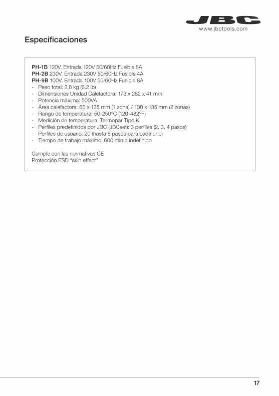
Especificaciones
PH-1B 120V. Entrada 120V 50/60Hz Fusible 8APH-2B 230V. Entrada 230V 50/60Hz Fusible 4APH-9B 100V. Entrada 100V 50/60Hz Fusible 8A- Peso total: 2,8 kg (6.2 lb)- Dimensiones Unidad Calefactora: 173 x 282 x 41 mm- Potencia máxima: 500VA- Área calefactora: 65 x 135 mm (1 zona) / 130 x 135 mm (2 zonas)- Rango de temperatura: 50-250°C (120-482ºF)- Medición de temperatura: Termopar Tipo K- Perfiles predefinidos por JBC (JBCset): 3 perfiles (2, 3, 4 pasos)- Perfiles de usuario: 20 (hasta 6 pasos para cada uno)- Tiempo de trabajo máximo: 600 min o indefinido
Cumple con las normativas CEProtección ESD “skin effect”
1717
www.jbctools.com

Inhalt
Die folgenden Teile sollten in dem Paket enthalten sein:
Heater UnitHeizgerät
Heater Unit Heizgerät ................................................1 Stück
ConsoleKonsole ....................................................1 Stück
Power Cord Netzkabel ................................................1 Stück
Kapton Tape Kaptonband ...........................................1 Stück
ThermocoupleThermoelement .....................................1 Stück
ConsoleKonsole
Power CordNetzkabelRef. 0009417(100V/120V) Ref. 0009401 (230V)
ThermocoupleThermoelementRef. PH218
Kapton TapeKaptonbandRef. PH217
Bedienungsanleitung
www.jbctools.com
Ref. PH-BIR Preheater
IR PreheaterUnterheizungPH-1B (120V)PH-2B (230V) PH-9B (100V)
181818

Eigenschaften
Steckanschluß für Konsole Steckanschluß für Pedal
Heizzone
Netzanschluss Netzschalter
Befestigungselementefür PH321 PCB-Halter
Heater Unit Heizgerät
ConsoleKonsole
Steuereinheit
Eingang für Hilfsthermoelement (Typ K)
Thermoelement(Typ K)
USB-B Anschluss zum PC:- Zum aktualisieren der Steuereinheits-software
Zone B
Zone A
191919
www.jbctools.com

Temperature Profiles (Temperaturprofile)
Warum Infrarot? Die effizienteste Technologie für die PCB Vorheizung
Betrieb
Der übliche Weg, um ein Profil ausführen zu lassen, ist die Verwendung des Thermoelements (TC), das mit dem Steuereingang der Konsole verbunden wird. JBC bietet drei vordefinierte Profile (JBC set) und 20 frei zu definierende Profile an.
JBCset Profiles (JBC vordefinierte Profile) Es gibt 3 vordefinierte JBC Profile: A, B und C. Der Unterschied zwischen ihnen ist die Anzahl der Stufen: 2, 3 oder 4. Je dicker Ihre Leiterplatte ist und je mehr Schichten enthalten sind, desto mehr Stufen sind notwendig, um eine allmähliche Erwärmung zu erhalten. Diese Profile können nicht geändert werden, aber sie können als Vorlage verwendet werden, um eigene Profile zu erstellen.
JBCset A2 Stufen
JBCset B3 Stufen
JBCset C4 Stufen
Dies ist die fortschrittlichste, effizienteste und kostengünstigste Methode, um Leiterplatten für jede beliebige Lötarbeit oder bei Reparaturarbeiten vorzuheizen. Die geringe thermische Masse des Infrarotelementes bietet eine hervorragende Kontrolle der Heizleistung und der Prozesstempera-tur. Diese Technologie bietet schnelle Reaktionszeiten, hohe Erwärmungsraten und gleichmäßige Erwärmung, was beste Ergebnisse sicherstellt.
Für sich wiederholende Arbeiten empfehlen wir Profile ohne Thermoelement (TC) laufen zu lassen. Sobald ein Profil bis zum Ende ausgeführt wurde, hat das System alle Prozessdaten und fragt, ob Sie sie speichern möchten. Wenn das der Fall ist, dann können Sie arbeiten ohne dass das Thermoelement angeschlossen ist. Der Erwärmungsvorgang wird identisch sein, solange die gleichen Arbeitsbedingungen eingehalten werden.
User profiles (Benutzerprofile) Basierend auf den JBC Profilen können Sie Ihre eigenen Profile erstellen. Auf dem Bildschirm drücken Sie die Enter-Taste und wählen die Option Enter Profile.
Power or Temperature Modes (Energie-Modus oder Temperatur-Modus)Das Gerät arbeitet mit der gewählten oder Temperatur Leistung während der definierten Zeit. Diese Parameter können vom Bildschirm aus durch drücken der Enter-Taste und dem Edit Parameters Menu geändert werden. Um die aktuelle Temperatur zu sehen, müssen Sie das Thermoelement (TC) anschliessen.
PCB Referenz Spezifikationen
FR4 1,6 mm dick und 2 Schichten.
FR4 2,2 mm dick und 6 Schichten.
FR4 1,6 mm dick und 6 Schichten.
Profil-Einstellungen (settings) unter Verwendung der niedrigen Position des PH321 PCB-Halters (28 mm position).
202020

Empfehlungen
1. Bringen Sie das Thermoelement so nah wie möglich bei der zu bearbeitenden Komponente an.
2. Wenn es ein besonders empfindliches Element auf der Leiteplatte gibt, benutzen Sie ein zusätzliches Hilfsthermoelement um dieses Bauteil zu schützen. Sie können die Schutztemperatur in dem Menu Station Settings auswählen. Wenn die gewählte Temperatur erreicht ist, wird das IR-Vorheiz-System den Prozess stoppen und eine Warnmeldung angezeigen.
Kapton-Band, um das Thermoelement (TC) auf der Leiterplatte zu fixieren
3. IPC* empfiehlt Anstiegsraten von 3 - 4 °C/s nicht zu überschreiten, um die Gefahr von thermischen Stress auf der Leiterplatte zu reduzieren.* IPC wurde in den USA im Jahr 1957 mit dem Namen Institute for Printed Circuits (Institut für Leiterplatten) gegründet.
Hilfsthermoelement (TC)
212121
www.jbctools.com
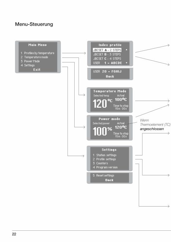
Menu-Steuerung
222222

232323
www.jbctools.com

Sicherheit
- Setzen Sie das Gerät nicht für einen anderen Zweck als zum Vorwärmen von PCB´s ein. Falsche Verwendung kann Brand verursachen.
- Das Netzkabel darf nur in zugelassenen Steckdosen eingesteckt werden. Achten Sie vor der Verwendung darauf, das die Steckdose ordnungsgemäss geerdet ist.
- Die Temperatur von zugänglichen Oberflächen kann hoch sein, auch wenn das Gerät ausges chaltet ist. Vorsicht beim Umgang.
- Lassen Sie das Gerät nicht unbeaufsichtigt, wenn es in Betrieb ist.
- Verdecken Sie nicht die Lüftungsgitter.
- Hitze kann dazu führen, brennbare Produkte zu entzünden, auch wenn diese nicht sichtbar sind.
- Seien Sie vorsichtig mit den Überresten von flüssigem Zinn. Bei Kontakt mit der Haut, kann es zu Verbrennungen führen.
- Verwenden Sie ein “non residue” eingestuftes Flussmittel und verhindern Sie Berührung mit der Haut oder den Augen, um Irritationen zu vermeiden.
- Seien Sie vorsichtig mit dem beim Löten erzeugten Lötrauch.
- Halten Sie Ihren Arbeitsplatz sauber und ordentlich. Tragen Sie eine geeignete Schutzbrille und Handschuhe bei der Arbeit, um Verletzungen zu vermeiden.
- Dieses Gerät kann von Kindern ab 8 Jahren und älter und von Personen mit eingeschränkten physischen, sensorischen oder geistigen Fähigkeiten oder mit mangelnder Erfahrung und Wissen benutzt werden, wenn eine angemessene Aufsicht oder ausführliche Anleitung zur sicheren Benutzung des Gerätes erfolgte und die damit verbundenen Gefahren verstanden wurden Kinder dürfen nicht mit dem Gerät spielen. Reinigung und Wartung dürfen nicht von Kindern ohne Beaufsichtigung eines Erwachsenen durchgeführt werden.
- Die Wartung der Geräte darf nur von einem After-Sales Service durchgeführt werden.
Es ist zwingend notwendig den Sicherheitsrichtlinien zu folgen, um die
Gesundheit zu schützen und Stromschlägen, Verletzungen, Brand oder
Explosionen vorzubeugen.
242424

Technische Daten
PH-1B 120V. Eingang 120V 50/60Hz Sicherung 8APH-2B 230V. Eingang 230V 50/60Hz Sicherung 4APH-9B 100V. Eingang 100V 50/60Hz Sicherung 8A- Gesamtgewicht: 2,8 kg (6.2 lb)- Maximale Leistung: 500 VA- Heizfläche: 65 x 135 mm (1 Zone) / 30 x 135 mm (2 Zonen) - Temperaturbereich: 50 bis 250 ºC (120-482ºF) - Temperaturmessung: Thermoelement Typ K - 3 JBCset Temperaturprofile - Bis zu 20 Benutzerprofile (bis zu 6 Schritte für jedes Profil) - Maximale Arbeitszeit: 600 min oder unbegrenzt
Entspricht den CE-NormenESD-geschütztes Gehäuse “Skin-Effekt”
252525
www.jbctools.com
www.jbctools.com
Ref. PH-BIR Preheater
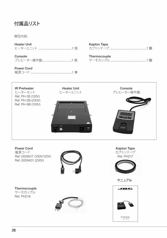
Power Cord電源コードRef. 0009417 (100V/120V) Ref. 0009401 (230V)
ThermocoupleサーモカップルRef. PH218
Kapton Tapeカプトンテープ
Ref. PH217
マニュアル
Heater Unit ヒーターユニット ...........................................1 個
Console プレヒーター操作盤......................................1 個
Power Cord 電源コード .....................................................1 本
Kapton Tape カプトンテープ ...............................................1 個
Thermocouple サーモカップル ..............................................1 個
付属品リスト
梱包内容:
Heater Unitヒーターユニット
Consoleプレヒーター操作盤
IR Preheater ヒーターセットRef. PH-1B (120V)Ref. PH-2B (230V) Ref. PH-9B (100V)
262626
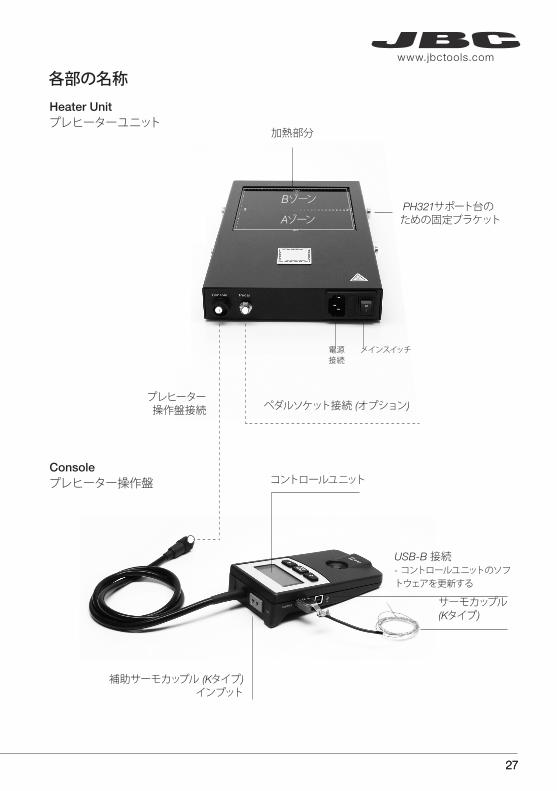
プレヒーター操作盤接続 ペダルソケット接続 (オプション)
加熱部分
電源接続
メインスイッチ
PH321サポート台のための固定ブラケット
Console プレヒーター操作盤 コントロールユニット
補助サーモカップル (Kタイプ) インプット
サーモカップル (Kタイプ)
USB-B 接続- コントロールユニットのソフトウェアを更新する
各部の名称Heater Unit プレヒーターユニット
Bゾーン
Aゾーン
272727
www.jbctools.com

Temperature Profiles (温度によるプロファイル)
なぜ赤外線なのか。PCBsプレヒーティングに最適なテクノロジーだからです。
使用方法
プロファイルの通常の使用方法はサーモカップル(TC)がプレヒーター操作盤のコントロールインプットに接続されている状態での使用になります。JBCは予め3つの定義付けされたプロファイル(JBCセット)と個人に合わせて設定できる20のプロファイルを提供します。
JBCset Profiles (JBCセットプロファイル) JBCによって予め定義された3つのプロファイル:A、B、C。3つの違いはステップの数:2、3、4。 PCBsが厚めなほどステップが必要になります。
JBCセット A2 ステップ
JBCセット B3 ステップ
JBCセット C4 ステップ
あらゆるタイプの半田ごて作業または、再作業において、PCBsを予め暖めておくのに最も進化した、有効で、費用効率の高い方法です。赤外線により暖められた小さな塊が熱放出とプロセス温度の調整を顕著にします。この技術は迅速なレスポンス、高度な加熱速度、加熱の一様化により、最良な結果をもたらします。
繰り返す作業のためにサーモカップル(TC)なしで、プロファイルを作動させるようお勧めします。一度、どれかのプロファイルで最後まで作動させると、システムは保存したプロセスデータを保有しています。一度保存されたら、サーモカップルを接続しなくてもそのプロファイルを作動させることができます。加熱プロセスは同じ作動環境が維持されていれば、同様に作動します。
User Profiles (ユーザープロファイリング)JBCセットプロファイルからお客様自身のプロファイルを作っていただくことができます。作業スクリーンで、Enterボタンを押し、プロファイルを編集するオプションを選択してください。
Power or Temperature Modes (電源や温度モード)ユニットは、定義された期間内の電力または選択された温度で動作します。このパラメーターはパラメーターメニューのEnterとEditボタンを押して、作業スクリーンから修正することができます。現時点の温度を見るためにサーモカップル(TC)をコントロール接続に差し込まなければなりません。
PCBs 参考仕様 : FR4 厚さ1,6mm 2層 FR4 厚さ2,2mm 6層FR4 厚さ1,6mm 6層
プロファイルはPH321プリント基板サポート台(PCBsと加熱部分の間の高さが28mm)低位置で使用されるようセットされています。
282828
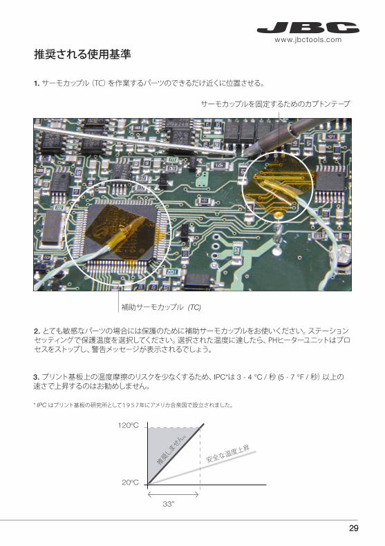
1. サーモカップル(TC)を作業するパーツのできるだけ近くに位置させる。
2. とても敏感なパーツの場合には保護のために補助サーモカップルをお使いください。ステーションセッティングで保護温度を選択してください。選択された温度に達したら、PHヒーターユニットはプロセスをストップし、警告メッセ−ジが表示されるでしょう。
サーモカップルを固定するためのカプトンテ−プ
3. プリント基板上の温度摩擦のリスクを少なくするため、IPC*は 3 - 4 °C / 秒 (5 - 7 °F / 秒)以上の速さで上昇するのはお勧めしません。
* IPC はプリント基板の研究所として1957年にアメリカ合衆国で設立されました。
補助サーモカップル (TC)
推奨される使用基準
292929
www.jbctools.com

コントロールディスプレイ
303030

313131
www.jbctools.com

安全のために
- PCBsプレヒーティング以外の目的で機器を使用しないでください。
- メインケーブルは正しく配置し、使用前に適正に接続されているか確認してください。
- 手に触れるフェイスの温度は電源切断後も熱いことがありますので、注意してください。
- 電源が入っている時に機器を放置しないでください。
- 換気口を塞がないようにしてください。
- 目に見えなくても可燃性の製品に発火する恐れがあります。
- 液体スズの残留には気をつけてください。肌に触れると、やけどをする可能性があります。
- 「残留なし」と分類された液体を使用し、炎症を起こさないように肌や目との接触を避けてください。
- はんだ付けの際に発生する煙に注意してください。
- 作業スペースは整然ときれいに片付けてください。けがのないよう、作業するときは防御メガネをかけ、手袋をしてください。
- この器具は8才以上のお子様、身体、感覚及び精神に障害のある方が使用される場合または経験や知識不足の場合は適正な監督及び器具の使用に関する説明を受け、関係する危険性を理解した上でご使用になるようお願いいたします。お子様の手の届かないところに置き、お子様が触らないようご注意ください。
- 機器のメンテナンスは指定されたアフターサービスまでお持ちください。
下記の注意事項に従い、健康を保護し、電気ショック、けが、火事または爆発を予防しなければなりません。
323232

主な仕様
PH-1B 120V. インプット 120V 50/60Hz ヒューズ 8APH-2B 230V. インプット 230V 50/60Hz ヒューズ 4APH-9B 100V. インプット 100V 50/60Hz ヒューズ 8A- 本体質量: 2,8 kg (6.2 lb)- 最大電圧: 500VA- 加熱部分: 65 x 135mm (1 ゾーン) 130 x 135mm (2 ゾーン)- 動作温度: 50 〜 250°C (120 から 482ºF)- 温度測定: サーモカップルKタイプ- JBC による3プロファイル(JBCセット)- ユーザープロファイル: 20プロファイルまで (各プロファイルに6ステップまで)- 最大作業時間: 600 分 / 無限の
CE 標準基準放電保証 “表皮効果”.
333333
www.jbctools.com

343434
清单
应包含以下项目:
Heater Unit加热器平台
Heater Unit加热器平台.................................................. 1 件
Console控制器 ......................................................... 1 件
Power Cord 电源线 ......................................................... 1 件
Kapton Tape 卡普顿胶带 ................................................ 1 件
Thermocouple热电偶 ........................................................ 1 件
Console控制器
Power Cord电源线 型号 0009417 (100V/120V) 型号 0009401 (230V)
Thermocouple热电偶型号 PH218
Kapton Tape 卡普顿胶带 型号 PH217
说明书
IR PreheaterIR预热器 型号 PH-1B (120V)型号 PH-2B (230V) 型号 PH-9B (100V)
Ref. PH-BIR Preheater
www.jbctools.com

353535
www.jbctools.com
特性
控制台插座连线
踏板接口连接(可选)
B区
加热区域
A区
控制屏
电源输入
电源开关
固定支架 PH321 支架
备用热电偶 ( K型)
热电偶(K型)
USB-B 电脑连接头:- 更新控制单元软件
Heater Unit加热器平台
Console 控制器

363636
Temperature profiles (温度曲线)
操作
JBC配置 A 2 步
JBC配置 B 3 步
JBC配置 C 4 步
对于重复性工作,我们建议使用没有热电偶(TC)的曲线。 一旦曲线已经运行完毕,系统会储存所有过程中的数据。 储存后,你就可以在没有热电偶(TC)的情况下直接运行曲线。 只要工作条件一致加热过程始终都是一样的。
通常运行曲线时使用连接到控制台的控制输入的热电偶(TC)。JBC提供3个预定义的曲线(JBC配置)和20个为你准备好的可个性化的曲线。
JBCset profiles (JBC配置 曲线) 有3个预定义的曲线:A,B和C。它们之间的区别是步数:2,3或4。 印刷电路板越厚,层数越高,就需要更多的步骤,以得到逐渐升温。 这些曲线不可修改,但它们可以被用来作为模板创建自己的曲线。
User Profiles (用户定义曲线) 你可以利用JBC配置曲线创建自己的曲线。 在曲线工作屏上按下回车键并选择编辑曲线。
线路板: FR4 1,6mm 厚度 和 2 层。参数
FR4 2,2mm厚 和 6 层FR4 1,6mm 厚 和 6 层
为什么红外线?这是线路板加热最有效的技术。这是焊接或返工中线路板预热的最先进,有效而经济的方法。红外线元件的低热容为热度输出和过程温度提供了出色的控制。该技术响应快速,具有高加热功率和均匀加热,确保了最好的结果。
Power or Temperature Modes (功率和溫度模式 )本机在预定时间内按照选择的功率工作。点激工作屏上的回车键后在参数菜单里可编辑修改这些参数。要看到现有工作参数,你必须将热电偶(TC)插入控制连接器内。
曲线设置使用PH321线路板支架低档(28mm在线路板和加热区域之间)。

373737
www.jbctools.com
推荐指南
固定TC的卡普顿胶带
1. 将热电偶(TC)尽可能接近到正在工作的组件。
2. 如果有敏感组件,请使用辅助热电偶保护。你可在工作台设置中选择保护温度。如果达到保护 温度,IR预热器会停止运行,警告信息会出现。
3. IPC*建议加速率不超过3 - 4°C/秒(5 - 12°F/秒),以减少线路板上热应力的风险。* IPC 于1957年在美国成立,全名为线路板学院。
辅助热电偶 (TC)

383838
屏幕控制

393939
www.jbctools.com
404040
安全注意事项
- 不要使用该产品在非线路板加热的其他任何目的。不正确的使用可能会导致火灾。
- 电源线必须插入认可的插座。确保使用前正确接地。
- 机组关闭后可触及表面仍然维持高温。小心轻放。
- 电器运行时不能无人看管。勿覆盖通风架。
- 高温可能引燃易燃产品,甚至是在视线看不见的地方。
- 小心液态锡的残留。它与皮肤接触可引起灼伤。
- 使用“无残渣”类助焊剂,避免与皮肤或眼睛接触,以防刺激。小心焊接过程中产生的烟雾。
- 保持工作环境的干净整洁。 工作时,为避免人身伤害需穿戴适当的防护眼镜和手套。
- 本设备可以由8岁以上儿童及成人操作,或者体能,感官缺陷或精神障碍者或缺乏经验及知识者使用,
前提是他们在被监督下或已被赋予相关安全操作的指令,并且了解可能存在的危险性。
儿童绝对不能玩耍该产品。清洁及维护不能由没有监督的儿童进行。
- 维护必须由授权的售后服务进行。
必须遵循安全规范,以保护健康,预防触电,人身伤害,火灾或爆炸。

414141
www.jbctools.com
技术参数
PH-1B 120V. 输入 120V 50/60Hz 保险丝 8APH-2B 230V. 输入230V 50/60Hz 保险丝 4APH-9B 100V. 输入100V 50/60Hz 保险丝 8A- 总重: 2.8 公斤 (6.2 磅)- 最大功率: 500VA- 加热区域: 65 x 135mm (1 个区) 130 x 135mm (2 个区)- 温度范围: 50 - 250°C (120 - 482ºF)- 温度计测: K型热电偶- 3 JBC配置 温度曲线- 用户配置曲线: 最多 20个 (每个配置最多6个)- 最大工作时间: 600 分钟 / 无限的
符合CE标准。ESD保护壳“趋肤效应”。

Exploded View · Despiece · Explosionszeichnung · 分解組立図 · 分解图
424242

Exploded View · Despiece · Explosionszeichnung · 分解組立図 · 分解图
434343
www.jbctools.com

保証JBCはすべての工場出荷状態での製品不具合に対して、不具合部品の交換と作業を含めて2年間補償します。使用後、または誤使用による不具合は補償できかねます。保証期間中は郵便料金支払済みの上、ご購入いただいた代理店まで返却ください。
この製品は一般ゴミと一緒に廃棄することできません。 ヨーロッパディレクティブ 2002/96/ECにより、電気製品を処分する場合は認定されたリサイクル設備に持ち込み、返却されなければなりません。
GarantieDie 2-Jahres-Garantie von JBC ersteckt sich auf das Gerät bei Herstellungsfehlern, einschließlich Fehlern der Verarbeitung und dem Ersatz defekter Teile und deren Austausch. Die Garantie gilt nicht für Produktverschleiß durch normale Nutzung oder durch falsche Anwendung. Damit die Garantie Gültigkeit erlangt, muß das Gerät an den Händler, bei dem es gekauft wurde, zurückgesand weden (Porto bezahlt).
Dieses Produkt sollte nicht mit dem Hausmüll entsorgt werden. In Übereinstimmung mit der europäischen Richtlinie 2002/96/EC müssen elektronische Geräte am Ende ihrer Lebensdauer eingesammelt und einem autorisierten Recyclingbetrieb zugeführt werden.
0013
384-
1114
GarantíaEsta garantía de 2 años cubre este equipo contra cualquier defecto de fabricación,incluyendo la sustitución de partes defectuosas y mano de obra.La garantía no cubre el desgaste del producto por uso o mal uso. Para que esta garantía sea válida, el equipo debe ser devuelto, a portes pagados, al distribuidor donde se compró.
Este producto no debe desecharse en la basura. De acuerdo a la directiva europea 2002/96/EC, los equipos electrónicos al final de su vida se deberán recoger y trasladar a una planta de reciclaje autorizada.
WarrantyJBC’s 2 year warranty covers this equipment against all manufacturing defects, including the replacement of defective parts and labour.Warranty does not cover product wear due to use or mis-use. In order for the warranty to be valid, equipment must be returned, postage paid, to the dealer where it was purchased.
This product should not be thrown in the garbage. In accordance with the European directive 2002/96/EC, electronic equipment at the end of their life must be collected and returned to an authorized recycling facility.
www.jbctools.com
保修JBC的2年保修涵盖了该设备所有的制造缺陷,包括更换损坏的零件和人工。保修不包括因使用或误用而产生的产品损坏。为了使保修有效, 设备邮资已付返回到购买时的经销 处返修。
本产品不应被扔在垃圾筒内。根据欧洲指令2002/96/EC,电子设备在其寿命结束后必须被收集并返回到授权回收工厂。