ir 25-2 - - /€¦ · · 2017-11-09ir 25-2.13 (rev 11-09-17) page 1 of 12 ... fasten hanger wires...
TRANSCRIPT

IR 25-2.13 METAL SUSPENSION SYSTEMS FOR LAY-IN PANEL CEILING: 2013 CBC Disciplines: Structural
History: Revised 11-09-17 Revised 05-16-13 Revised 04-20-17 Revised 12-21-12 Revised 02-10-16 Revised in its entirety 05-18-11
Revised in its entirety 09-21-15 Issued 06-22-09 as IR 25-5 Revised 04-08-14
PURPOSE: The purpose of this Interpretation of Regulations (IR) is to provide guidelines for the design and installation of metal suspension systems for lay-in ceilings on projects submitted under the 2013 California Building Code (CBC). For projects submitted to the Division of the State Architect (DSA) for review under the 2007 or 2010 CBC, see DSA IR 25-2.07 or IR 25-2.10, respectively.
1. GENERAL REQUIREMENTS: CBC Section 1616A.1.20 (1616.10.16*) requires the design and installation to be in compliance with ASTM C635, C636, and E580, Section 5, with modifications.
Note: Amendments in CBC Section 1616A.1.20 (1616.10.16*) replace and append ASCE 7, Section 13.5.6.
The requirements in this IR apply to flat and level ceiling systems whose total weight, including ceiling mounted air terminals, services and light fixtures, does not exceed four (4) psf. Heavier systems, systems that are not flat and level, those supporting lateral loads from partitions, and free floating ceilings supported by chains or cables are beyond the minimum requirements of this IR and will require special design and details.
2. CEILING DESIGN & INSTALLATION REQUIREMENTS: 2.1 Ceiling System Components:
a) Shall comply with ASTM C635 and Section 5.1 of ASTM E580.
b) The ceiling grid system must be rated heavy duty as defined by ASTM C635.
c) Main runners, cross runners, splices, expansion devices and intersection connectors shall be designed to carry a mean ultimate test load of not less than 180 lbs. in compression and tension per ASTM E580 Section 5.1.2.
d) Ceiling wire shall be Class 1 zinc coated (galvanized) carbon steel conforming to ASTM A641. Wire shall be #12 gauge (0.106" diameter) with soft temper and minimum tensile strength = 70 ksi. The maximum allowable (ASD) tension load for wire meeting this specification is 350 lbs. • Four (4) turns of the wire within 1.5" will develop the wire allowable load. • Three (3) turns of the wire within 3" is assumed to develop no more than 50
percent of wire allowable load.
2.2 Suspension System Installation: a) Shall comply with ASTM C636 and Section 5.2 of ASTM E580.
b) #12 gauge hanger wires may be used for up to and including a 4 foot by 4 foot grid spacing and shall be attached to main runners. Splices in hanger wires shall develop 50 percent of the wire allowable load.
c) Provide #12 gauge hanger wires at the ends of all main and cross runners within eight (8) inches of the support or within one-fourth (1/4) of the length of the end tee,
IR 25-2.13 (rev 11-09-17) Page 1 of 12 DIVISION OF THE STATE ARCHITECT DEPARTMENT OF GENERAL SERVICES STATE OF CALIFORNIA

DSA IR 25-2.13 METAL SUSPENSION SYSTEMS FOR LAY-IN PANEL CEILINGS: 2013 CBC
whichever is least, for the perimeter of the ceiling area. Perimeter wires are not required when the length of the end tee is eight (8) inches or less.
d) Ceiling grid members shall be attached to two (2) adjacent walls per ASTM E580, Section 5.2.3. Ceiling grid members shall be at least 3/4 inch clear of other walls. If walls run diagonally to ceiling grid system runners, one end of main and cross runners should be free, and a minimum of 3/4 inch clear of wall.
e) The width of the perimeter supporting closure angle shall be not less than two (2) inches. Use of angles with smaller widths in conjunction with proprietary perimeter clips may be acceptable in accordance with Section 5 of this IR.
f) At the perimeter of the ceiling area, where main or cross runners are not connected to the adjacent wall, provide interconnection between the runners at the free end to prevent lateral spreading. A metal stabilizer or a #16 gauge wire with a positive mechanical connection to the runner may be used and placed within eight (8) inches of the wall. Where the perpendicular distance from the wall to the first parallel runner is eight (8) inches or less, the stabilizer or #16 gauge wire is not required.
2.3 Lateral Force Bracing Assembly Installation: a) Lateral force bracing assemblies consisting of a compression strut and four (4) #12
gauge splayed bracing wires oriented 90 degrees from each other are required for all ceiling areas.
Exception: Lateral force bracing may be omitted for suspended acoustical ceiling systems with a ceiling area not to exceed 144 square feet, for all values of SDS, when perimeter support is provided in accordance with Section 2.2 of this IR and perimeter walls are designed to carry the ceiling lateral forces.
b) Lateral force bracing assemblies shall be spaced per Table 1 for all values of the component importance factor (Ip) of the ceiling.
c) There shall be a brace assembly a distance of not more than one-half (1/2) of the above spacing from each surrounding wall, expansion joint and at the edges of any ceiling vertical offset. For example, where the brace spacing is 8' x 12', the edge distance shall be 4 feet in the direction of the 8 foot spacing and 6 feet in the direction of the 12 foot spacing.
d) The slope of bracing wires shall not exceed 45 degrees from the horizontal plane and wires shall be taut. Splices in bracing wires shall develop the wire allowable load.
e) Compression struts shall meet the following requirements: • The strut shall be sized to adequately resist the vertical component force induced
by the ceiling bracing wires and have a maximum kl/r not to exceed 300. The struts listed in Appendix A meet this requirement for ceilings complying with the general requirements of this IR.
• The strut shall not be more than one (horizontal) in six (vertical) out of plumb.
IR 25-2.13 (rev 11-09-17) Page 2 of 12 DIVISION OF THE STATE ARCHITECT DEPARTMENT OF GENERAL SERVICES STATE OF CALIFORNIA

DSA IR 25-2.13 METAL SUSPENSION SYSTEMS FOR LAY-IN PANEL CEILINGS: 2013 CBC
TABLE 1 LATERAL FORCE BRACE ASSEMBLY SPACING
Design Spectral Acceleration Parameter, SDS Brace Assembly Spacing (ft.)
z/h ≤ 0.5a z/h > 0.5a,b
SDS ≤ 1.15 12 x 12 12 x 12
1.15 < SDS ≤ 1.73 12 x 12 8 x 12
SDS > 1.73 8 x 12 8 x 8
Footnotes: a. Where, as defined in ASCE 7, Section 13.3.1: z = height in structure of point of attachment of ceiling with respect to the base. h = average roof height of the structure with respect to the base. b. It shall be permitted to use the brace assembly spacing for “z/h > 0.5” for the full
building height.
2.4 Attachment of Hanger and Bracing Wires: a) Fasten hanger wires with not less than three (3) tight turns in three (3) inches.
Hanger wire loops shall be tightly wrapped and sharply bent to prevent any vertical movement or rotation of the member within the loops (see ASTM E580, Section 5.2.7.2).
b) Fasten bracing wires with not less than four (4) tight turns in one and one-half (1-1/2) inches.
c) Hanger and bracing wire anchorage to the structure shall be installed in such a manner that the direction of the anchorage aligns closely with the direction of the wire (e.g. bracing wire ceiling clips must be bent as shown in the details and rotated as required to align closely with the direction of the wire, screw eyes in wood must be installed so they align closely with the direction of the wire, etc.).
d) Separate all ceiling hanger and bracing wires at least six (6) inches from all unbraced ducts, pipes, conduit, etc.
e) Hanger and bracing wires shall not attach to or bend around obstructions including but not limited to: piping, ductwork, conduit and equipment. Provide trapeze or other supplementary support members at obstructions to allow typical hanger spacing. Brace assemblies must be configured and/or located in order to avoid obstructions in addition to maintaining the required brace assembly spacing.
f) Provide additional hangers, struts and brace assemblies as required at all ceiling breaks, soffits or discontinuous areas.
g) Hanger wires that are more than one (horizontal) in six (vertical) out of plumb shall have counter-sloping wires.
Note: See ASTM C636, Figure 1, for counter-sloping methods.
h) Attachment of the bracing wires to the structure above and to the main runners shall be adequate for the load imposed. The weight (Wp) shall be taken as not less than four (4) psf for calculating seismic forces (Fp).
i) Post-installed anchors (e.g. expansion anchors, screw anchors and power actuated fasteners) shall have a current Evaluation Report acceptable to DSA in accordance with DSA IR A-5.
IR 25-2.13 (rev 11-09-17) Page 3 of 12 DIVISION OF THE STATE ARCHITECT DEPARTMENT OF GENERAL SERVICES STATE OF CALIFORNIA
DSA IR 25-2.13 METAL SUSPENSION SYSTEMS FOR LAY-IN PANEL CEILINGS: 2013 CBC
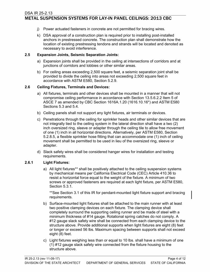
j) Power actuated fasteners in concrete are not permitted for bracing wires.
k) DSA approval of a construction plan is required prior to installing post-installed anchors in prestressed concrete. The construction plan shall demonstrate how the location of existing prestressing tendons and strands will be located and denoted as necessary to avoid interference.
2.5 Expansion Joints, Seismic Separation Joints: a) Expansion joints shall be provided in the ceiling at intersections of corridors and at
junctions of corridors and lobbies or other similar areas.
b) For ceiling areas exceeding 2,500 square feet, a seismic separation joint shall be provided to divide the ceiling into areas not exceeding 2,500 square feet in accordance with ASTM E580, Section 5.2.9.
2.6 Ceiling Fixtures, Terminals and Devices: a) All fixtures, terminals and other devices shall be mounted in a manner that will not
compromise ceiling performance in accordance with Section 13.5.6.2.2 Item 5 of ASCE 7 as amended by CBC Section 1616A.1.20 (1616.10.16*) and ASTM E580 Sections 5.3 and 5.4.
b) Ceiling panels shall not support any light fixtures, air terminals or devices.
c) Penetrations through the ceiling for sprinkler heads and other similar devices that are not integrally tied to the ceiling system in the lateral direction shall have a two (2) inch oversized ring, sleeve or adapter through the ceiling tile to allow free movement of one (1) inch in all horizontal directions. Alternatively, per ASTM E580, Section 5.2.8.5, a flexible sprinkler hose fitting that can accommodate one (1) inch of ceiling movement shall be permitted to be used in lieu of the oversized ring, sleeve or adapter.
d) Slack safety wires shall be considered hanger wires for installation and testing requirements.
2.6.1 Light Fixtures: a) All light fixtures** shall be positively attached to the ceiling suspension systems
by mechanical means per California Electrical Code (CEC) Article 410.36 to resist a horizontal force equal to the weight of the fixture. A minimum of two screws or approved fasteners are required at each light fixture, per ASTM E580, Section 5.3.1. **See Section 3.1 of this IR for pendant-mounted light fixture support and bracing requirements.
b) Surface-mounted light fixtures shall be attached to the main runner with at least two positive clamping devices on each fixture. The clamping device shall completely surround the supporting ceiling runner and be made of steel with a minimum thickness of #14 gauge. Rotational spring catches do not comply. A #12 gauge slack safety wire shall be connected from each clamping device to the structure above. Provide additional supports when light fixtures are eight (8) feet or longer or exceed 56 lbs. Maximum spacing between supports shall not exceed eight (8) feet.
c) Light fixtures weighing less than or equal to 10 lbs. shall have a minimum of one (1) #12 gauge slack safety wire connected from the fixture housing to the structure above.
IR 25-2.13 (rev 11-09-17) Page 4 of 12 DIVISION OF THE STATE ARCHITECT DEPARTMENT OF GENERAL SERVICES STATE OF CALIFORNIA

DSA IR 25-2.13 METAL SUSPENSION SYSTEMS FOR LAY-IN PANEL CEILINGS: 2013 CBC
d) Light fixtures weighing greater than 10 lbs. but less than or equal to 56 lbs. may be supported directly on the ceiling runners, but they shall have a minimum of two (2) #12 gauge slack safety wires connected from the fixture housing at diagonal corners to the structure above.
Exception: All light fixtures greater than two by four feet weighing less than 56 lbs. shall have a #12 gauge slack safety wire at each corner.
e) All light fixtures weighing greater than 56 lbs. shall be independently supported by not less than four (4) taut #12 gauge hanger wires (one at each corner) attached from the fixture housing to the structure above or other approved hangers. The four (4) taut #12 gauge wires or other approved hangers, including their attachment to the structure above, shall be capable of supporting four (4) times the weight of the fixture.
2.6.2 Services within the Ceiling: a) All flexible sprinkler hose fitting mounting brackets, ceiling-mounted air terminals
or other services shall be positively attached to the ceiling suspension systems by mechanical means to resist a horizontal force equal to the weight of the component. Screws or approved fasteners are required. A minimum of two attachments are required at each component.
b) Ceiling-mounted air terminals or other services weighing less than or equal to 20 lbs. shall have one (1) #12 gauge slack safety wire attached from the terminal or service to the structure above.
c) Flexible sprinkler hose fittings, ceiling-mounted air terminals or other services weighing more than 20 lbs. but less than or equal to 56 lbs. shall have two (2) #12 gauge slack safety wires (at diagonal corners) connected from the terminal or service to the structure above.
d) Flexible sprinkler hose fittings, ceiling-mounted air terminals or other services weighing more than 56 lbs. shall be supported directly from the structure above by not less than four (4) taut #12 gauge hanger wires attached from the terminal or service to the structure above or other approved hangers. The four (4) taut #12 gauge wires or other approved hangers, including their attachment to the structure above, must be capable of supporting four (4) times the weight of the unit.
2.6.3 Other Devices within the Ceiling: All lightweight miscellaneous devices, such as strobe lights, occupancy sensors, speakers, exit signs, etc., shall be attached to the ceiling grid per Section 2.6.2 a) of this IR. In addition, devices weighing more than 10 lbs. shall have a #12 gauge slack safety wire anchored to the structure above per Section 2.6.1 b) of this IR. Devices weighing more than 20 lbs. shall be supported from the structure above using details provided by the registered design professional.
3. ADDITIONAL REQUIREMENTS: 3.1 Pendant-Mounted Light Fixtures:
a) Where pendant-mounted light fixtures are to be installed in areas with a suspended ceiling, the construction documents shall include complete support details complying with this IR and DSA IR 16-9.
b) Support pendant-mounted light fixtures directly from the structure above with hanger wires or cables passing through each pendant hanger and capable of supporting two
IR 25-2.13 (rev 11-09-17) Page 5 of 12 DIVISION OF THE STATE ARCHITECT DEPARTMENT OF GENERAL SERVICES STATE OF CALIFORNIA

DSA IR 25-2.13 METAL SUSPENSION SYSTEMS FOR LAY-IN PANEL CEILINGS: 2013 CBC
(2) times the weight of the fixture.
c) If a pendant-mounted light fixture is directly and independently braced below the ceiling (i.e., aircraft cables to walls), then a brace assembly is not required above the ceiling.
d) If a pendant-mounted light fixture is free to swing 45 degrees from vertical in all directions, and is not directly and independently braced below the ceiling, then a bracing assembly is only required where the pendant hanger penetrates the ceiling. Special details are required to attach the pendant hanger to the bracing assembly to transmit the horizontal and vertical forces.
Exception: Where the weight of the fixture is less than 20 lbs., the vertical component of the brace force need not be considered so no compression strut/post is required.
e) Rigid conduit shall not be used for attachment of the fixtures.
3.2 Fire Rated Ceilings:
a) Provide a detail and tested assembly number for rated ceiling assemblies from an authorized testing agency. The components and installation details must conform in every respect with the listed detail and number. Details shall clearly depict all components, including insulation materials, framing and attachment of the design so that the assembly can be constructed and inspected accordingly.
b) Pop rivets, screws or other attachments are not acceptable unless specifically detailed in the listed construction detail(s), or an approved listing by a State Fire Marshal (SFM) recognized laboratory.
3.3 Acoustical Ceiling Tile Panel Installation: For ceiling installations utilizing acoustical tile panels of mineral or glass fiber, it is not
mandatory to provide 3/4 inch clearance between the acoustical tile panels and the wall on the sides of the ceiling which are free to slip.
3.4 Other Panel Types: Panels weighing more than one-half (1/2) psf, other than mineral fiber and glass fiber acoustical tile, and all metal and wood panels shall be positively attached to the ceiling suspension runners by mechanical means, such as bolts, screws or rivets, and each attachment shall have the allowable design strength to support 100 percent of the weight of the panel acting in any direction. A minimum of two attachments are required for each panel. For ceiling installations utilizing panels other than mineral or glass fiber, 3/4 inch clearance shall be provided between the ceiling panel and the wall on the sides of the ceiling area which are free to slip, unless otherwise justified by seismic qualification indicated below.
The use of other types of attachment, such as clips, snap-in devices, perforated lips, clamping devices or spring loaded devices or hooks, shall be listed per DSA IR A-5 and identified for use with the type of ceiling framing members and panels. The listing shall be seismically qualified in accordance with ASCE 7 Section 13.2.5 or 13.2.6.
An alternate means of compliance per California Administrative Code (CAC), Section 4-304 may be proposed and reviewed on a project-by-project basis when using unlisted means of attachment. The alternate means of attachment shall have the allowable design strength to support 100 percent of the weight of the panel acting in any direction and shall be capable of maintaining that strength if the ceiling grid is distorted or out of level.
IR 25-2.13 (rev 11-09-17) Page 6 of 12 DIVISION OF THE STATE ARCHITECT DEPARTMENT OF GENERAL SERVICES STATE OF CALIFORNIA

DSA IR 25-2.13 METAL SUSPENSION SYSTEMS FOR LAY-IN PANEL CEILINGS: 2013 CBC
It is also alternately permitted to provide a secondary means of connecting the panel to the grid or structure to retain the panel in case of panel dropout, ceiling grid distortion and ceiling grid becoming out-of-level. The secondary attachment shall have the allowable design strength to support two (2) times the weight of the panel acting in any direction, such as a slack wire or cable.
Special attachment details complying with one of the methods outlined above, such as screws or cables, shall be provided at the perimeter of the ceiling, where panels are cut or altered, or where non-standard panel sizes or edge conditions occur.
3.5 Exitways: Exitways of essential services buildings shall be installed in accordance with Section 13.5.6.2.2 Item 1 of ASCE 7 as amended by CBC Section 1616A.1.20 (1616.10.16*). A main or cross runner shall be installed on all sides of each piece of tile, board or panel and each light fixture or grill. Splices or intersection of such runners shall be attached with through connectors such as pop rivets, screws, pins, plates with end tabs or other approved connectors.
3.6 Free Floating Ceilings: Free floating ceilings (ceilings not attached to any walls) supported by wires in
accordance with this IR shall be braced in accordance with this IR, regardless of the ceiling area, unless it can be demonstrated the anticipated ceiling movement will not cause failure of the ceiling components or failure of mechanical, electrical, plumbing and fire and life safety components/systems within the ceiling area and within the area of anticipated movement.
The perimeter of free floating ceilings shall be supported by a continuous runner which is spliced in accordance with ASTM E580 Section 5.1.2.
4. CEILING SYSTEM ALTERATION: The entire1 ceiling in the affected space shall be upgraded to meet the current requirements of the CBC and this IR if any portion of the grid system is cut or altered and the ceiling has no lateral bracing assemblies2 (4-way splay wires and compression post) or has lateral bracing assemblies spaced more than 12 feet on-center.
Exception: If the ceiling has lateral bracing assemblies spaced no more than 12 feet on-center, a ceiling upgrade will only be required if the area cut or altered exceeds 10 percent of the entire ceiling area.
Notes: 1. The “entire” ceiling in the affected space is defined as the area of ceiling bounded
by four walls or a combination of walls and expansion joints or seismic separation joints.
2. With DSA concurrence, other existing lateral bracing systems may be deemed equivalent to a 4-way splay wire and compression post lateral force bracing system.
4.1 Where the ceiling grid is not cut or altered, and the scope of work includes only the following: • replacement of existing ceiling panels with like panels of equal or lesser weight • replacement of light fixtures and/or terminals with like units (units of equal size and of
equal or lesser weight) placed in the same location
no upgrade to the ceiling grid, suspension system or lateral force brace assemblies is
IR 25-2.13 (rev 11-09-17) Page 7 of 12 DIVISION OF THE STATE ARCHITECT DEPARTMENT OF GENERAL SERVICES STATE OF CALIFORNIA

DSA IR 25-2.13 METAL SUSPENSION SYSTEMS FOR LAY-IN PANEL CEILINGS: 2013 CBC
required.
4.2 Re-Use of Existing Ceiling Hanger Wires and Bracing Wires: Existing ceiling hanger and bracing wires may be reused provided they comply with the following:
a) The gauge and spacing of the wires must comply with the current applicable codes and this IR.
b) If a new wire is to be spliced to an existing wire, the architect or structural engineer in general responsible charge must submit to DSA for approval a detail and specification describing how the splice is to be made. Acceptable wire splice details are provided in Appendix A.
c) See Section 7 of this IR for testing requirements for the re-use of existing hanger and bracing wire assemblies.
5. DSA ACCEPTANCE OF EVALUATION REPORTS: Ceiling grid systems or components, with valid evaluation reports issued by qualified evaluation agencies, in accordance with DSA IR A-5, are accepted by DSA, provided the system or component meets the requirements of CBC Section 1616A.1.20 (1616.10.16*), ASTM C635, C636 and E580. Where a qualified evaluation report is utilized, the installation shall comply with all the requirements specified in the evaluation report, i.e., connections, member sizes, perimeter details, special clips to wall angles, etc.
In accordance with DSA IR A-5, DSA will accept OSHPD Preapproved Details (OPD) “2013 CBC Standard Suspended Ceiling Details for Acoustical Tile or Lay-in Panel Ceilings.”
6. CONSTRUCTION DOCUMENTS: The construction documents shall clearly identify all suspended ceiling systems, support details, and lateral bracing.
6.1 General Requirements: The items listed in this section are required to be provided in the construction documents where applicable to the project scope. This list includes items common to most projects but is not complete for all projects. Additional information and/or details may be required on the construction documents for a specific project for specialty conditions, configurations, products, etc.
Except as indicated in both Section 6.2 and Appendix A of this IR, it is not permitted to reproduce this IR on the construction documents as a means to meet these requirements.
6.1.1 Ceiling Systems. A list of acceptable grid systems must be shown on the construction documents. Each system specified must be classified as heavy duty and shall have a valid evaluation report in accordance with DSA IR A-5. The construction documents shall specify the following for each acceptable grid system: the manufacturer, product name, evaluation report number, main and cross runner catalog number, and if used, seismic wall clip. When manufacturer specific information (proprietary seismic wall clips, etc.) is provided in the specifications, details on the construction drawings shall be provided and/or coordinated to reflect the same manufacturer specific information.
6.1.2 Ceiling Suspension System. The ceiling suspension system and its anchorage to the structure shall be fully detailed.
Where accepted proprietary devices, clips, wall angles, etc. are utilized, the details on the construction documents shall clearly indicate the installation details necessary to show compliance with all evaluation report requirements.
6.1.3 Ceiling Lateral Force Bracing. The ceiling lateral force bracing system, including the bracing wires and compression strut, and the bracing system anchorage to the
IR 25-2.13 (rev 11-09-17) Page 8 of 12 DIVISION OF THE STATE ARCHITECT DEPARTMENT OF GENERAL SERVICES STATE OF CALIFORNIA

DSA IR 25-2.13 METAL SUSPENSION SYSTEMS FOR LAY-IN PANEL CEILINGS: 2013 CBC
structure shall be fully detailed on the construction documents. The bracing assembly spacing at each floor and roof level must be clearly indicated.
6.1.4 Expansion Joints and Seismic Separations Joints. Expansion joints and seismic separation joints shall be fully detailed and the location shall be shown on the ceiling plans.
6.1.5 Ceiling Fixtures, Terminals and Devices Anchorage and Bracing. Details of construction for all fixtures, terminals, flexible fire sprinkler hose fittings and other devices must be provided as required to comply with this IR.
6.1.6 Pendant-Mounted Light Fixtures. Where pendant-mounted light fixtures are to be installed in areas with a suspended ceiling, the construction documents shall include complete support details complying with this IR and DSA IR 16-9.
6.1.7 Supplementary Support Members. Trapeze or other supplementary support members provided so typical hanger spacing can be maintained while avoiding obstructions shall be shown on the construction documents.
6.1.8 Partition Bracing. Partition bracing shall be shown on the construction documents and be braced independent of the ceiling system.
6.2 Ceiling Notes and Details in Appendix A: The ceiling notes and details provided in Appendix A are deemed to meet the general requirements of this IR. These notes and details shall not be used for construction or inspection except when incorporated in DSA approved construction documents.
Use of the notes and details is not mandated by DSA; they are provided only as a convenience to the registered design professional for incorporation into the construction documents.
Use of other notes and details created by the registered design professional is always acceptable provided they comply with the CBC and this IR. While these notes and details do not cover every condition that may occur on every project, they are intended to cover conditions common to many projects, and it is anticipated their use will facilitate the design, plan review and construction process.
Electronic drawing files of the details created using Revit LTTM 2015 are available for download at http://www.documents.dgs.ca.gov/dsa/pubs/DSA-IR_25-2-13_CeilingDetails_2017_0310_R3.zip. DSA is providing these electronic drawing files to the registered design professional for convenience only and DSA is not responsible for issues of compatibility with particular computer systems or conversion to other file formats. The requirements of this IR are in no way changed or modified by providing the registered design professional with the electronic drawing files. The files may not be currently up to date or in conformance with the published IR and the registered design professional shall verify and coordinate the information with the latest published IR. Information contained in the files may be changed or updated by DSA, and DSA shall have no responsibility to notify or supply the registered design professional with these changes.
6.2.1 Conditions for Use of Ceiling Notes and Details. The conditions and requirements for use of the ceiling notes and details in Appendix A are as follows:
a) The details give no consideration to suitability for use in a specific application, compatibility with other building systems, appropriate use of materials or design, appearances, etc. The registered design professionals listed on the plan review application shall review all such qualities, features and/or properties to ensure code compliance, appropriate integration with other building systems, and proper
IR 25-2.13 (rev 11-09-17) Page 9 of 12 DIVISION OF THE STATE ARCHITECT DEPARTMENT OF GENERAL SERVICES STATE OF CALIFORNIA

DSA IR 25-2.13 METAL SUSPENSION SYSTEMS FOR LAY-IN PANEL CEILINGS: 2013 CBC
design for the project-specific conditions and installation.
b) When the details in the Appendix are used, they shall be incorporated into the construction drawings submitted for DSA approval. Incorporation by reference alone is not permitted. Only the notes and details applicable to the scope of the project shall be incorporated in the construction documents (e.g., do not incorporate wood connection details in the construction drawings for a concrete structure, do not include essential services building details in the construction documents for a school project, etc.).
c) Provided the content of the details is not changed, it is left to the discretion of the registered design professional(s) to reconfigure (renumber, resize, etc.) the details for integration into the construction drawings.
Exception: The registered design professional(s) is required to provide additional information on a detail where brackets [ ] are indicated. The brackets and notes to the registered design professional shall be removed from the details and replaced with the applicable requirements.
d) These details submitted as part of the construction documents during the plan review process will be subject to plan review as follows: • It is expected no DSA plan review comment will be made on a detail
incorporated into the construction documents that is unaltered and found applicable to the project for which it is submitted.
• Where a detail requires the designer to provide additional information to complete the detail before applying it to the drawings, plan review will be limited to the following: o A review of only the additional information provided. o A review to determine if the detail, with the additional information, is
applicable to project for which it is submitted. • Where a detail incorporated into the construction documents has been
altered beyond that indicated in c) and d) above, it will be subject to a full review for both detail content and applicability to the project for which it is submitted.
e) Where conditions not covered by the details in Appendix A occur, project-specific design and details will be required. This includes, but is not limited to, pendant light fixtures, projector supports, projector screens, ceiling fans and free-floating ceilings.
7. TESTING: All field testing must be performed in the presence of the project inspector or a special inspector.
7.1 New Installations: Post-installed anchors in concrete used to support hanger wires shall be tested at a frequency of 10 percent. Power actuated fasteners in concrete shall be field tested for 200 lbs. in tension. All other post-installed anchors in concrete shall be tested in accordance with CBC Section 1913A.7.
Post-installed anchors in concrete used to attach bracing wires shall be tested at a frequency of 50 percent in accordance with CBC Section 1913A.7.
7.2 Re-Use of Existing Ceiling Hanger Wires and Bracing Wires: a) All existing ceiling hanger wire/anchor assemblies must be field tested to 200 lbs.
b) All existing bracing wire/anchor assemblies must be field tested to 440 lbs.
IR 25-2.13 (rev 11-09-17) Page 10 of 12 DIVISION OF THE STATE ARCHITECT DEPARTMENT OF GENERAL SERVICES STATE OF CALIFORNIA

DSA IR 25-2.13 METAL SUSPENSION SYSTEMS FOR LAY-IN PANEL CEILINGS: 2013 CBC
c) Where a new wire is spliced to an existing wire, each spliced wire/anchor assembly must be field tested to the loads given for existing assemblies above.
REFERENCES: California Code of Regulations (CCR) Title 24 Part 2, 2013 California Building Code (CBC), Section 1616A.1.20, 1616.10.16* Part 3, 2013 California Electrical Code (CEC), Article 410.36 ASCE 7-10 Minimum Design Loads for Building and Other Structures ASTM C635.07, C636-08, and E580-10a
This Interpretation of Regulations (IR) is intended for use by the Division of the State Architect (DSA) staff and by design professionals to promote more uniform statewide criteria for plan review and construction inspection of projects within the jurisdiction of DSA which includes State of California public elementary and secondary schools (grades K–12), community colleges and state-owned or state-leased essential services buildings. This IR indicates an acceptable method for achieving compliance with applicable codes and regulations, although other methods proposed by design professionals may be considered by DSA.
This IR is reviewed on a regular basis and is subject to revision at any tim e. Please check DSA’s website for currently effective IRs. Only IRs listed on the webpage at www.dgs.ca.gov/dsa/Resources/IRManual.aspx at the time of plan submittal to DSA are considered applicable.
*Indicates alternative 2013 CBC sections that may be used by community colleges, per 2013 CBC Section 1.9.2.2.
IR 25-2.13 (rev 11-09-17) Page 11 of 12 DIVISION OF THE STATE ARCHITECT DEPARTMENT OF GENERAL SERVICES STATE OF CALIFORNIA

DSA IR 25-2.13 METAL SUSPENSION SYSTEMS FOR LAY-IN PANEL CEILINGS: 2013 CBC
APPENDIX A: CONSTRUCTION DOCUMENTS CEILING NOTES AND DETAILS
IR 25-2.13 (rev 11-09-17) Page 12 of 12 DIVISION OF THE STATE ARCHITECT DEPARTMENT OF GENERAL SERVICES STATE OF CALIFORNIA

Appendix A
Sheet Index
SHEET NO. SHEET TITLE REV. DATE 0.00 Sheet Index
0.01 Sheet Index
1.00 Ceiling Notes
1.01 Ceiling Notes
1.02 Ceiling Notes
1.03 Ceiling Notes
2.10 Typical Ceiling Plan for 8’-0” X 8’-0” Brace Assembly Spacing
2.11 Typical Ceiling Plan for 8’-0” X 12’-0” Brace Assembly Spacing
2.12 Typical Ceiling Plan for 12’-0” X 12’-0” Brace Assembly Spacing
2.30 Suspended Acoustical Ceiling – Corridor Ceiling Plan (Schools)
2.31 Suspended Acoustical Ceiling – Corridor Ceiling Plan (ESB1)
2.35 Suspended Ceiling – Suspension and Bracing Assembly
2.40 Suspended Acoustical Ceiling – Expansion Joint at Intersections (Schools)
2.41 Suspended Acoustical Ceiling – Expansion Joint at Intersections (ESB1)
2.45 Suspended Acoustical Ceiling – Seismic Separation Joint
2.50 Typical Ceiling Section @ Exitway Corridors (ESB1)
2.60 Ceiling Perimeter
2.80 Suspended Acoustical Ceiling – Light Fixture/Air Terminal Support
3.10 Suspended Acoustical Ceiling – Channel Type Strut
3.20 Suspended acoustical Ceiling – EMT Type Strut
3.21 Compression Strut Table
4.10 Hanger and Bracing Wire Connections – Typical Wire Turns
4.11 Hanger and Bracing Wire Connections Matrix
4.20 Hanger Wire Connection to Metal Deck
1ESB – Essential Services Buildings
Basis Document: DSA IR 25-2.13 Sheet No:
0.00 Sheet Title:
Sheet Indexrev. 09-21-15
DSA IR 25-2.13 - Appendix A (rev 11/09/17)
1 of 51

Sheet Index
SHEET NO. SHEET TITLE REV. DATE 4.21 Hanger Wire Connection to Concrete Over Metal Deck
4.22 Hanger Wire Connection to Concrete Slab, Beam, or Joist
4.23 Hanger Wire Connection to Structural Steel
4.24 Hanger Wire Connection to Metal Stud Wall
4.25 Hanger Wire Connection to Sawn Timber
4.26 Hanger Wire Connection to Wood I Joist
4.27 Hanger Wire Connection to Wood Chord Truss
4.28 Hanger Wire Connection to Open Web Steel Joist
4.29 Typical Saddle Tie Detail
4.30 Bracing Wire Connection at Metal Deck
4.31 Bracing Wire Connection to Concrete Over Metal Deck
4.32 Bracing Wire Connection to Concrete Slab, Beam, or Joist
4.33 Bracing Wire Connection to Structural Steel
4.34 Bracing Wire Connection to Metal Stud Wall
4.35 Bracing Wire Connection to Sawn Timber
4.36 Bracing Wire Connection to Wood I Joist
4.37 Bracing Wire Connection to Wood I Joist
4.38 Bracing Wire Connection to Wood Chord Truss
4.39 Bracing Wire Connection to Open Web Steel Joist
5.10 Compression Strut Connection to Structure – Connection Matrix
5.20 Strut Connection to Metal Deck
5.21 Strut Connection to Concrete Over Metal Deck
5.30 Strut Connection to Concrete Slab, Beam, or Joist
5.40 Strut Connection to Structural Steel
5.50 Strut Connection to Sawn Timber with Gypsum Board
5.60 Strut Connection to Sawn Timber without Gypsum Board
6.10 Ceiling Wire Splices
Basis Document: DSA IR 25-2.13 Sheet No:
0.01 Sheet Title:
Sheet Index rev. 09-21-15
DSA IR 25-2.13 - Appendix A (rev 11/09/17)
2 of 51

1. CEILING SYSTEM GENERAL NOTES:
1.01 Ceiling system components shall comply with ASTM C635-07 and Section 5.1 of ASTM E580-10a.
1.02 The ceiling grid system must be rated heavy duty as defined by ASTM C635-08.
1.03 Ceiling systems. The following ceiling system(s) is/are part of the scope of this project: [For each system used, the RDP shall indicate in the construction documents, the information that follows]
Manufacturer's Name _____________ __. Product Evaluation Report Type and Number __________________. Manufacturer's Model Number - main runner ______________ __ . Manufacturer's catalog number - cross runner _________________ .
1.04 Seismic Wall Clip: [RDP to specify if used]
Manufacturer’s Model _____________ __ .
1.05 Ceiling panels shall not support any light fixtures, air terminals or devices.
1.06 For ceiling installations utilizing acoustical tile panels of mineral or glass fiber, it is not mandatory to provide ¾” clearance between the acoustical tile panels and the wall on the sides of the ceiling which are free to slip. For all other ceiling panel types, provide ¾” clearance between the ceiling panel and the wall on the sides of the ceiling free to slip.
2. MATERIALS:
2.01 Ceiling wire shall be Class 1 zinc coated (galvanized) carbon steel conforming to ASTM A641-09a. Wire shall be #12 gage (0.106” diameter) with soft temper and minimum tensile strength = 70 ksi.
2.02 Galvanized sheet steel (including that used for metal stud and track compression struts/post) shall conform to ASTM A653-11, or other equivalent sheet steel listed in Section A2.1 of the North American Specification for the Design of Cold-Formed Steel Structural Members 2007, including supplement 2 dated 2010 (AISI S100-07/S2-10). Material 43 mil (18 gage) and lighter shall have minimum yield strength of 33 ksi. Material 54 mil (16 gage) and heavier shall have a minimum yield strength of 50 ksi.
2.03 Electrical metallic tube (EMT) shall be ANSI C80.3/UL 797 carbon steel with G90 galvanizing. EMT shall have minimum yield strength (Fy) of 30 ksi and minimum ultimate strength (Fu) of 48 ksi.
Basis Document: DSA IR 25-2.13 Sheet No:
1.00 Sheet Title:
Ceiling Notes rev. 09-21-15
DSA IR 25-2.13 - Appendix A (rev 11/09/17)
3 of 51

3. ATTACHMENT OF HANGER AND BRACING WIRES:
3.01 Separate all ceiling hanger and bracing wires at least six (6) inches from all unbraced ducts, pipes, conduit, etc.
3.02 Hanger and bracing wires shall not attach to or bend around obstructions including but not limited to: piping, ductwork, conduit and equipment.
3.03 Hanger wires that are more than one (horizontal) in six (vertical) out of plumb shall have counter-sloping wires.
3.04 Slack safety wires shall be considered hanger wires for installation and testing requirements. 3.05 Hanger and bracing wire anchorage to the structure shall be installed in such a manner that
the direction of the anchorage aligns closely with the direction of the wire. (e.g. bracing wire ceiling clips must be bent as shown in the details and rotated as required to align closely with the direction of the wire, screw eyes in wood must be installed so they align closely with the direction of the wire, etc.)
4. FASTENERS AND WELDING:
4.01 Sheet metal screws shall comply with ASTM C1513-10, ASME B18.6.4-89 (R2005). Penetration of screws through joined material shall not be less than three exposed threads.
4.02 Expansion anchors shall be: [RDP to indicate manufacturer, product, evaluation report number and load for each size specified per CBC 1913A.7.2.]
4.03 Power-Actuated Fasteners shall be: [RDP to indicate manufacturer, product, evaluation report number]
4.04 If not otherwise specified in the evaluation report, power-actuated fasteners installed in steel shall be installed so the entire pointed end of the fastener is driven through the steel member.
4.05 Power-actuated fasteners in concrete are not permitted for bracing wires.
4.06 Concrete reinforcement and prestressing tendons shall be located by non-destructive means prior to installing post - installed anchor.
4.07 Welding shall be in accordance with AWS D1.3 using E60XX series electrodes.
5. TESTING: All field testing must be performed in the presence of the project inspector.
5.01 Post-installed anchors in concrete used to support hanger wires shall be tested at a frequency of 10 percent. Power actuated fasteners in concrete shall be field tested for 200 lbs. in tension. All other post-installed anchors in concrete shall be tested in accordance with CBC Section 1913A.7.
5.02 Post-installed anchors in concrete used to attach bracing wires shall be tested at a frequency of 50 percent in accordance with CBC Section 1913A.7.
Basis Document: DSA IR 25-2.13 Sheet No:
1.01 Sheet Title:
Ceiling Notes rev. 09-21-15
DSA IR 25-2.13 - Appendix A (rev 11/09/17)
4 of 51

6. LIGHT FIXTURES:
6.01 All light fixtures shall be positively attached to the ceiling suspension systems by mechanical means to resist a horizontal force equal to the weight of the fixture. A minimum of two screws or approved fasteners are required at each light fixture, per ASTM E580, Section 5.3.1.
6.02 Surface-mounted light fixtures shall be attached to the main runner with at least two positive clamping devices. The clamping device shall completely surround the supporting ceiling runner and be made of steel with a minimum thickness of #14 gage. Rotational spring catches do not comply. A #12 gage slack safety wire shall be connected from each clamping device to the structure above. Provide additional supports when light fixtures are eight (8) feet or longer or exceed 56 lb. Maximum spacing between supports shall not exceed eight (8) feet.
6.03 Light fixtures weighing less than or equal to 10 lb. shall have a minimum of one (1) #12 gage slack safety wire connected from the fixture housing to the structure above.
6.04 Light fixtures weighing less than or equal to 10 lb. shall have a minimum of one (1) #12 gage slack safety wire connected from the fixture housing to the structure above.
6.05 Light fixtures weighing greater than 10 lb. but less than or equal to 56 lbs. may be supported directly on the ceiling runners, but they shall have a minimum of two (2) #12 gage slack safety wires connected from the fixture housing at diagonal corners to the structure above.
Exception: All light fixtures greater than two by four feet weighing less than 56 lbs. shall have a #12 gage slack safety wire at each corner.
6.06 All Light fixtures weighing greater than 56 lb. shall be independently supported by not less than four (4) taut #12 gage hanger wires (one at each corner) attached from the fixture housing to the structure above or other approved hangers. The four (4) taut #12 gage wires or other approved hangers, including their attachment to the structure above, shall be capable of supporting four (4) times the weight of the fixture.
7. SERVICES WITHIN THE CEILING:
7.01 All flexible sprinkler hose fitting mounting brackets, ceiling-mounted air terminals or other services shall be positively attached to the ceiling suspension systems by mechanical means. Screws or approved fasteners are required. A minimum of two attachments are required at each component.
7.02 Ceiling-mounted air terminals or other services weighing less than or equal to 20 lb. shall have one (1) #12 gage slack safety wire attached from the terminal or service to the structure above.
7.03 Flexible sprinkler hose fittings, ceiling-mounted air terminals or other services weighing more than 20 lb. but less than or equal to 56 lb. shall have two (2) #12 gage slack safety wires (at diagonal corners) connected from the terminal or service to the structure above.
7.04 Flexible sprinkler hose fittings, ceiling-mounted air terminals or other services weighing more than 56 lb. shall be supported directly from the structure above by not less than four (4) taut #12 gage hanger wires attached from the terminal or service to the structure above or other approved hangers.
Basis Document: DSA IR 25-2.13 Sheet No:
1.02 Sheet Title:
Ceiling Notes rev. 09-21-15
DSA IR 25-2.13 - Appendix A (rev 11/09/17)
5 of 51

8. OTHER DEVICES WITHIN THE CEILING:
8.01 All lightweight miscellaneous devices, such as strobe lights, occupancy sensors, speakers, exit signs, etc., shall be attached to the ceiling grid. In addition, devices weighing more than 10 lbs. shall have a #12 gage slack safety wire anchored to the structure above. Devices weighing more than 20 lb. shall be supported independently from the structure above.
Basis Document: DSA IR 25-2.13 Sheet No:
1.03 Sheet Title:
Ceiling Notes rev. 09-21-15
DSA IR 25-2.13 - Appendix A (rev 11/09/17)
6 of 51

9/1
4/2
015
2:16
:02
PM
FREE JOINT
ATTACHED JOINT
CROSS RUNNERS TYP.
BRACING WIRE LOCATION-TYP.
STABILIZER BARS, CROSS TEES OR STRUTS 8" MAX. FROM WALL TYP. ALONG FREE JOINTS
CONT ANGLE @ PERIMETER
FREE JOINT
NOTE:
BRACING WIRES AND COMP. STRUT SHALL OCCUR AT EVERY 64 SQ. FT. MAX. IN ROOMS OVER 144 SQ. FT.
MAIN RUNNERS
2.60
MAX
4' - 0"
MAX
8' - 0"
MAX
4' - 0"
MA
X
4' -
0"
MA
X
8' -
0" ATTACHED JOINT
2.60
2.60 ATTACHED JOINT
MA
X
4' -
0"
64 SQ FT MAX
2.60 FREE JOINT
Typical 2.35
[WHERE A PROPRIETARYSEISMIC CLIP IS SPECIFIED, RDP TO REMOVE THE STABILIZER BARS SHOWN ON THE PLAN AND THE ABOVE STABILIZER BAR NOTE]
Basis Document : DSA IR 25-2.13 Sheet No:
2.10Sheet Title : TYPICAL CEILING PLAN FOR
8'-0" X 8'-0" Brace Assembly Spacing
rev. 09-21-15
DSA IR 25-2.13 - Appendix A (rev 11/09/17)
7 of 51

9/1
4/2
015
2:16
:02
PM
FREE JOINT CONT ANGLE @ PERIMETER
NOTE:
BRACING WIRES AND COMP. STRUT SHALL OCCUR AT EVERY 96 SQ. FT. MAX. IN ROOMS OVER 144 SQ. FT.
2.60
2.60
96 SQ FT
MAX
MAX
4' - 0"
MAX
8' - 0"
MAX
4' - 0"
ATTACHED JOINT
MA
X
6' -
0"
MA
X
12'
-0"
MA
X
6' -
0"
FREE JOINT
2.60 FREE JOINT
ATTACHED JOINT
CROSS RUNNERS TYP.
BRACING WIRE LOCATION-TYP.
MAIN RUNNERS
STABILIZER BARS, CROSS TEES OR STRUTS 8" MAX. FROM WALL TYP. ALONG FREE JOINTS
2.60 ATTACHED JOINT
Typical 2.35
[WHERE A PROPRIETARYSEISMIC CLIP IS SPECIFIED, RDP TO REMOVE THE STABILIZER BARS SHOWN ON THE PLAN AND THE ABOVE STABILIZER BAR NOTE]
Basis Document : DSA IR 25-2.13 Sheet No:
2.11Sheet Title : TYPICAL CEILING PLAN FOR
8'-0" x 12'-0" Brace Assembly Spacing
rev. 09-21-15
DSA IR 25-2.13 - Appendix A (rev 11/09/17)
8 of 51

FREE JOINT
ATTACHED JOINT
CROSS RUNNERS TYP.
BRACING WIRE LOCATION-TYP.
CONT ANGLE @ PERIMETER
NOTE:
BRACING WIRES AND COMP. STRUT SHALL OCCUR AT EVERY 144 SQ. FT. MAX. IN ROOMS OVER 144 SQ. FT.
MAIN RUNNERS
STABILIZER BARS, CROSS TEES OR STRUTS 8" MAX. FROM WALL TYP. ALONG FREE JOINTS
MAX
6' - 0"
MAX
12' - 0"
MAX
6' - 0"
MA
X
6' -
0"
MA
X
12'
-0"
MA
X
6' -
0"
2.60
2.60
ATTACHED JOINT
FREE JOINT
2.60 FREE JOINT
2.60 ATTACHED JOINT
144 SQ FT MAX
Typical 2.35
[WHERE A PROPRIETARYSEISMIC CLIP IS SPECIFIED, RDP TO REMOVE THE STABILIZER BARS SHOWN ON THE PLAN AND THE ABOVE STABILIZER BAR NOTE]
Sheet No: Basis Document :
Sheet Title :
DSA IR 25-2.13 rev. 09-21-15
9/1
4/2
015
2:16
:02
PM
2.12TYPICAL CEILING PLAN FOR 12'-0" x 12'-0" Brace Assembly Spacing
DSA IR 25-2.13 - Appendix A (rev 11/09/17)
9 of 51

9/1
4/2
015
2:16
:03
PM
2.60
2.60
2.40
2.40
FREE JOINT
EXPANSION JOINT
FREE JOINT
ATTACHED JOINT
FREE JOINT
ATTACHED JOINT
ATTACHED JOINT CONNECTED TO WALL
LOCATION OF EXPANSION/SLIP JOINTS IN CORRIDORS
O.H.
12'-0" MAX (TYP)
"L/2" MAX
"L/2" MAX.
FREE JOINT
(TYP.) 4'-0" MAX.
(TYP)
"L" MAX.
TYPICAL STRUT AND BRACING
2.35
NOTES:
1. "L"IS MAX. BRACE ASSEMBLY SPACING PER CEILING PLAN DETAIL, FOR EXAMPLE, WHERE 8' x 12' SPACING IS SPECIFIED, USE "L" = 8'.
STABILIZER BARS, CROSS TEES OR STRUTS 8" MAX. FROM WALL TYP. ALONG FREE JOINTS
[WHERE A PROPRIETARY SEISMIC CLIP ISSPECIFIED, RDP TO REMOVE THE STABILIZER BARS SHOWN ON THE PLAN AND THE ABOVE STABILIZER BAR NOTE]
*
*
*
*
*
*
*
* *
*
*
*
*
**
*
*
*
*
[IF THE "ATTACHED JOINT" WALLS AREDESIGNED TO RESIST PERPENDICULAR LATERAL LOAD FROM THE CEILING, THE RDP SHALL REMOVE THE STRUT BRACING ONLY IN THE DIRECTION PERPENDICULAR TO THE CORRIDOR MARKED WITH AN ASTERISK (*) AND ALSO THE ASTERISK (*)FROM THE PLAN, OTHERWISE REMOVE ONLY THE ASTERISK (*).]
Basis Document : DSA IR 25-2.13 Sheet No:
2.30Sheet Title : SUSPENDED ACOUSTICAL CEILING-
CORRIDOR CEILING PLAN (Schools)
rev. 09-21-15
DSA IR 25-2.13 - Appendix A (rev 11/09/17)
10 of 51

9/1
4/2
015
2:16
:03
PM
2.50
2.50
2.41
2.41
FREE JOINT
EXPANSION JOINT
FREE JOINT
ATTACHED JOINT
FREE JOINT
ATTACHED JOINT
ATTACHED JOINT CONNECTED TO WALL
LOCATION OF EXPANSION/SLIP JOINTS IN CORRIDORS
12'-0" MAX (TYP)
4'-0" MAX
4'-0" MAX
FREE JOINT
(TYP) 4'-0" MAX
(TYP)
8'-0" MAX
STRUT AND
BRACING TYP.
2.35
2.60
@ NON-EXITWAYS
@ EXITWAYS
@ EXITWAYS
2.60 @ NON-EXITWAYS *
*
*
*
*
*
*
*
*
*
*
*
*
*
*
*
*
*
*
*
STABILIZER BARS, CROSS TEES OR STRUTS 8" MAX. FROM WALL TYP. ALONG FREE JOINTS AT NON-EXITWAYS.
[AT NON-EXITWAYS WHERE A PROPRIETARYSEISMIC CLIP IS SPECIFIED, RDP TO REMOVE THE STABILIZER BARS SHOWN ON THE PLAN AND THE ABOVE STABILIZER BAR NOTE]
[IF THE "ATTACHED JOINT" WALLS ARE DESIGNED TO RESISTPERPENDICULAR LATERAL LOAD FROM THE CEILING, THE RDP SHALL REMOVE THE STRUT BRACING ONLY IN THE DIRECTION PERPENDICULAR TO THE CORRIDOR MARKED WITH AN ASTERISK (*) AND ALSO THE ASTERISK (*) FROMTHE PLAN, OTHERWISE REMOVE ONLY THE ASTERISK (*).]
Basis Document : DSA IR 25-2.13 Sheet No:
2.31Sheet Title : SUSPENDED ACOUSTICAL CEILING-
CORRIDOR CEILING PLAN (Essential Sevices Buildings)
rev. 09-21-15
DSA IR 25-2.13 - Appendix A (rev 11/09/17)
11 of 51

3/1
0/2
01
7 1
1:3
4:4
3 A
M
3.10 3.20
STRUTS SHALL NOT REPLACE HANGER WIRES.
THE MINIMUM ACCEPTABLE ANGLE IS DETERMINED SUCH THAT THE WIRES DO NOT INTERFERE WITH THE RUNNERS, LIGHT FIXTURES, ETC. AND REMAIN STRAIGHT AND UNOBSTRUCTED.
NOTES:
RIGID VERT. STRUT
SEE DET. OR
4.10
12 GA VERTICAL HANGERS AT 4'-0" O.C. EACH WAY AT MAIN RUNNER WITH MINIMUM 3-TIGHT TURNS IN 3" AT BOTH ENDS, SEE
CROSS RUNNER
1.
.
0° TO 45° (NOTE 2)
2'-0" TYP
4'-0"
2'-0" TYP
2.
4.10
12 GA. BRACING WIRE W/MIN. 4-TIGHT TURNS IN 1 1/2" BOTH ENDS OF WIRE CONNECTED TO MAIN RUNNERS 90º APART, 4-TOTAL AT EACH STRUT (U.N.O.) SEE
SEE DETAIL 3.10 & 3.20 FOR LOCATION OF BRACING WIRES AND STRUT
MAIN RUNNER
6 MIN
1
Basis Document : DSA IR 25-2.13 Sheet No:
2.35 Sheet Title :
SUSPENDED CEILING - SUSPENSION
AND BRACING ASSEMBLY
rev. 09-21-15
rev.
DSA IR 25-2.13 - Appendix A (rev 11/09/17)
12 of 51

9/1
4/2
015
2:16
:03
PM
STEEL POP RIVET
STEEL POP RIVET
CONT. RUNNERS (SPLICE ALL JOINTS)
TYP. HANGER WIRES @ 4'-0" O.C.
EXPANSION JOINT ALTERNATE
8" MAX. 8" MAX.
COVER PLATE WITH 1" FLEXIBILITY MINIMUM IN ALL DIRECTIONS
1" CLEAR
EXPANSION JOINTS AT THE INTERSECTION OF CORRIDORS AND AT JUNCTIONS OF CORRIDORS AND LOBBIES OR OTHER SIMILAR AREAS
NOTES: 1. PROVIDE #12 GAGE HANGER WIRES AT THE ENDS OF ALL MAIN AND CROSS
RUNNERS WITHIN EIGHT (8) INCHES OF THE SUPPORT OR WITHIN ONE-FOURTH (1/4) OF THE LENGTH OF THE END TEE, WHICHEVER IS LESS, FOR THE
PERIMETER OF THE CEILING AREA. PERIMETER WIRES ARE NOT REQUIRED WHEN THE LENGTH OF THE END TEE IS EIGHT (8) INCHES OR LESS.
(SEE NOTE 1 BELOW) (SEE NOTE 1 BELOW)
POP RIVET @ EACH RUNNER (TYP.)
STEEL POP RIVET
WALL MOULDING
HANGER WIRE @ EACH RUNNER
8" MAX. 8" MAX.
CONTINUOS WALL MOULDING 1" CLEAR
(SEE NOTE 1 BELOW) (SEE NOTE 1 BELOW)
EXPOSED CEILING TEES FIELD CUT TO LENGTH
SPLICE WALL MOULDING BY CLIPPING HORIZONTAL LEG, LAP VERTICAL LEG & INSTALL (3)- #8 SMS (TYP.)
EXPANSION JOINT
Basis Document : DSA IR 25-2.13 Sheet No:
2.40Sheet Title : SUSPENDED ACOUSTICAL CEILING -
EXPANSION JOINT AT INTERSECTIONS
rev. 09-21-15
DSA IR 25-2.13 - Appendix A (rev 11/09/17)
13 of 51

9/1
4/2
015
2:16
:03
PM
TYPICAL SPLICE @ CROSS RUNNERS
TYP. HANGER WIRES @ 4'-0"
O.C.
RUNNER SPLICE
MAIN RUNNER
CROSS RUNNER
NOTES: 1. PROVIDE #12 GAGE HANGER WIRES AT THE ENDS OF ALL
MAIN AND CROSS RUNNERS WITHIN EIGHT (8) INCHES OF THE SUPPORT OR WITHIN ONE-FOURTH (1/4) OF THE LENGTH OF THE END TEE, WHICHEVER IS LESS, FOR THE PERIMETER OF THE CEILING AREA. PERIMETER WIRES ARE NOT REQUIRED WHEN THE LENGTH OF THE END TEE IS EIGHT (8) INCHES OR LESS.
STEEL POP RIVET
STEEL POP RIVET
CONT. RUNNERS (SPLICE ALL JOINTS)
TYP. HANGER WIRES @ 4'-0"
O.C.
EXPANSION JOINT
8" MAX. 8" MAX.
COVER PLATE WITH 1" FLEXIBILITY MINIMUM IN ALL DIRECTIONS
1" CLEAR
(SEE NOTE 1 BELOW) (SEE NOTE 1 BELOW)
EXPANSION JOINTS AT THE INTERSECTION OF CORRIDORS AND AT JUNCTIONS OF CORRIDORS AND LOBBIES OR OTHER SIMILAR AREAS
Basis Document : DSA IR 25-2.13 Sheet No:
2.41Sheet Title : SUSPENDED ACOUSTICAL CEILING -
EXPANSION JOINT AT INTERSECTIONS (Essential Services Buildings)
rev. 09-21-15
DSA IR 25-2.13 - Appendix A (rev 11/09/17)
14 of 51

9/1
4/2
015
2:16
:03
PM
SEISMIC SEPARATION JOINT
SEISMIC SEPARATION JOINT AT CONTINUOUS CEILING AREAS EXCEEDING 2500 SQ. FT. SEE CEILING PLANS FOR LOCATION
NOTES: 1. PROVIDE #12 GAGE HANGER WIRES AT THE ENDS OF ALL MAIN AND CROSS RUNNERS WITHIN EIGHT (8) INCHES OF THE SUPPORT OR WITHIN ONE-FOURTH (1/4) OF THE LENGTH OF THE END TEE, WHICHEVER IS LESS, FOR THE PERIMETER OF THE CEILING AREA. PERIMETER WIRES ARE NOT REQUIRED WHEN THE LENGTH OF THE END TEE IS EIGHT (8) INCHES OR LESS.
STEEL POP RIVET
STEEL POP RIVET
CONT. RUNNERS (SPLICE ALL JOINTS)
TYP. HANGER WIRES @ 4'-0" O.C.
8" MAX. 8" MAX.
COVER PLATE WITH 1" FLEXIBILITY MINIMUM IN ALL DIRECTIONS
1" CLEAR
(SEE NOTE 1 BELOW) (SEE NOTE 1 BELOW)
POP RIVET @ EACH RUNNER (TYP.)
STEEL POP RIVET
WALL MOULDING
HANGER WIRE @ EACH RUNNER
8" MAX. 8" MAX.
CONTINUOS WALL MOULDING 1" CLEAR
(SEE NOTE 1 BELOW) (SEE NOTE 1 BELOW)
EXPOSED CEILING TEES FIELD CUT TO LENGTH
SPLICE WALL MOULDING BY CLIPPING HORIZONTAL LEG, LAPVERTICAL LEG & INSTALL (3)- #8 SMS (TYP.)
ALTERNATE SEISMIC SEPARATION JOINT
Basis Document : DSA IR 25-2.13 Sheet No:
2.45Sheet Title : SUSPENDED ACOUSTICAL CEILING -
SEISMIC SEPARATION JOINT
rev. 09-21-15
DSA IR 25-2.13 - Appendix A (rev 11/09/17)
15 of 51
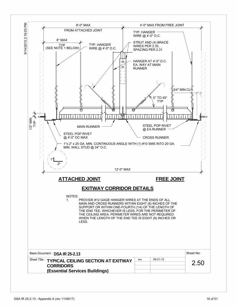
TY
P
1/2
"M
IN
94
//
52
21
116:
:0
03
PM
STEEL POP RIVET @ 4'-0" OC MAX
1"x 2" x 25 GA. MIN. CONTINUOUS ANGLE WITH (1) #10 SMS INTO 20 GA. MIN. WALL STUD @ 24" O.C.
TYP. HANGER WIRE @ 4'-0" O.C.
STEEL POP RIVET @ EA.RUNNER
TYP. HANGER WIRE @ 4'-0" O.C.
3/4" MIN.CLR.
ATTACHED JOINT FREE JOINT
EXITWAY CORRIDOR DETAILS
MAIN RUNNER
CROSS RUNNER
4'-0" MAX FROM FREE JOINT
STRUT AND (4) BRACE WIRES PER 2.35, SPACING PER 2.31
HANGER AT 4'-0" O.C. EA. WAY AT MAIN RUNNER
0° TO 45° TYP
12'-0" MAX
TYP
8" MAX
FROM ATTACHED JOINT
8'-0" MAX
(SEE NOTE 1 BELOW)
NOTES: 1. PROVIDE #12 GAGE HANGER WIRES AT THE ENDS OF ALL
MAIN AND CROSS RUNNERS WITHIN EIGHT (8) INCHES OF THE SUPPORT OR WITHIN ONE-FOURTH (1/4) OF THE LENGTH OF THE END TEE, WHICHEVER IS LESS, FOR THE PERIMETER OF THE CEILING AREA. PERIMETER WIRES ARE NOT REQUIRED WHEN THE LENGTH OF THE END TEE IS EIGHT (8) INCHES OR LESS.
1" 2"
Basis Document : DSA IR 25-2.13 Sheet No:
2.50Sheet Title : TYPICAL CEILING SECTION AT EXITWAY
CORRIDORS (Essential Services Buildings)
rev. 09-21-15
DSA IR 25-2.13 - Appendix A (rev 11/09/17)
16 of 51

3.
3/1
0/2
01
7 1
1:3
4:4
3 A
M
ATTACHED JOINT FREE JOINT
NOTES:
1. PROVIDE #12 GAGE HANGER WIRES AT THE ENDS OF ALL MAIN AND CROSS RUNNERS WITHIN EIGHT (8) INCHES OF THE SUPPORT OR WITHIN ONE-FOURTH (1/4) OF THE LENGTH OF THE END TEE, WHICHEVER IS LESS, FOR THE PERIMETER OF THE CEILING AREA. PERIMETER WIRES ARE NOT REQUIRED WHEN THE LENGTH OF THE END TEE IS EIGHT (8) INCHES OR LESS.
CONT. SLOTTED ANGLE STABILIZER BAR W/ HORIZ. 6d RINGSHANK NAIL (NOTE 2). OMIT STRUT WHERE RUNNER IS WITHIN 8" OF WALL .
ALTERNATE STABILIZER LOCATION W/O NAIL (NOTE 3)
HANGER WIRE
MAIN OR CROSS RUNNER
CEILING PANEL
STEEL POP RIVET @ ATTACHED SIDE ONLY
CHANNEL. (STABILIZER BAR)
RUNNER
(SEE NOTE 1 BELOW)
8" MAX.
(SEE NOTE 1 BELOW)
8" MAX.
2. NAILS AT ENDS OF HORIZONTAL STABILIZERS ARE TO BE PLACED WITH NAIL HEAD TOWARD CENTER LINE OF SPAN OF STRUT.
3/4" MIN. CLR.
APPROVED STABILIZER
1" x 2" x 25 GA. MIN. CONTINUOUS ANGLE WITH (1) #10 SMS INTO 20 GA. MIN. WALL STUD @ 24" O.C.
(TY
P.)
1
/2"
MIN
.
[RDP TO REVISE DETAIL AND NOTE IF SMALLER ANGLE IS USED IN CONJUCTION WITH A PROPRIETARY SEISMIC CLIP. PROVIDE COMPLETE DETAILS OF CONSTRUCTION FOR PROPRIETARY CLIP.]
(SEE NOTE 3)
NOTE #4
STABILIZER BAR MAY BE SLOTTED APPROVED ANGLES OR CHANNELS WITH "DIAMOND POINTS" OF SPRING STEEL WHICH SNAP TIGHT TO PREVENT MOVEMENT OF STRUT.
3.
(1) #10 SMS TO 20 GA. MIN. WALL STUD @ 24" O.C. 4.
1"
2"
[WHERE A PROPRIETARY SEISMIC CLIP IS SPECIFIED, RDP TO REMOVE FROM THE DETAIL ALL REFERENCES REGARDING STABILIZERS.]
Basis Document : DSA IR 25-2.13 Sheet No:
2.60 Sheet Title :
CEILING PERIMETER rev. 09-21-15
rev.
DSA IR 25-2.13 - Appendix A (rev 11/09/17)
17 of 51

AM
142
:5 1
0:20
16/1
0/2
AIR TERMINAL ORLIGHT FIXTURE(56# MAX.)
(2) 12 GA. SLACK SAFETY WIREHANGERS FOR DEVICES THAT WEIGHLESS THAN 56 LBS PLACE ONDIAGONAL CORNERS.
EXCEPTION: FIXTURES GREATERTHAN 2 FEET X 4 FEET WEIGHINGLESS THAN 56 LBS. REQUIRE A 12 GA.SLACK SAFETY WIRE HANGER AT EA.CORNER.
1-#8 S.M.S. IN OPPOSITE SIDES (2TOTAL) LOCATE SCREWS NEARTHE CENTER OF TERMINAL ORFIXTURE
HEAVY DUTY SYSTEM
Basis Document : DSA IR 25-2.13 Sheet No:
2.80Sheet Title : SUSPENDED ACOUSTICAL CEILING -
LIGHT FIXTURES/ AIR TERMINALSUPPORT DETAIL
rev. 09-21-15
rev. 02-10-16
DSA IR 25-2.13 - Appendix A (rev 11/09/17)
18 of 51

.X
CD
OO
OW
AA
BLL
LL
GG
VII
NN
NN
TT
TT
TH
HH
EE
EE
EE
EE
AB
3.2
1F
HM
PI
OO
OO
NN
RR
RU
SS
SS
LL
CC
TT
TT
TE
EE
EE
ED
9/
/5
22
11
16::
00
44
PM
5.10
FOR CONNECTION TO STRUCTURE SEE
(2) 1/4"DIA. MACHINE BOLT
CROSS RUNNER
3/4" MIN. EDGE DISTANCE,TYP.
HANGER WIRE
3 TIGHT TURNS IN 3" FOR HANGER TYP.
MAX 1 1/2"
.
MAX
4'-0" OC
TYP 3/4" MIN
MAIN RUNNER
HANGER WIRE BEYOND
COPE FLANGE OR FLATTEN TO ALLOW INSTALLATION OF ACOUSTICAL TILE
3" = 1'-0" A SECTION
4.10
STRUCTURE
BRACE WIRES SEE
MAIN RUNNER
4 TIGHT TURNS IN 1 1/2" TYP. FOR BRACE WIRE
TYP
0º
TO
45º
CHANNEL TYPE COMPRESSION STRUT PER TABLE 0N 3.21 CENTERED OVER CROSS RUNNER
MAX 1 1/2"
1" MAX
A
CROSS RUNNER
BRACE WIRE BEYOND
Basis Document : DSA IR 25-2.13 Sheet No:
3.10Sheet Title : SUSPENDED ACOUSTICAL CEILING -
CHANNEL TYPE STRUT
rev. 09-21-15
DSA IR 25-2.13 - Appendix A (rev 11/09/17)
19 of 51
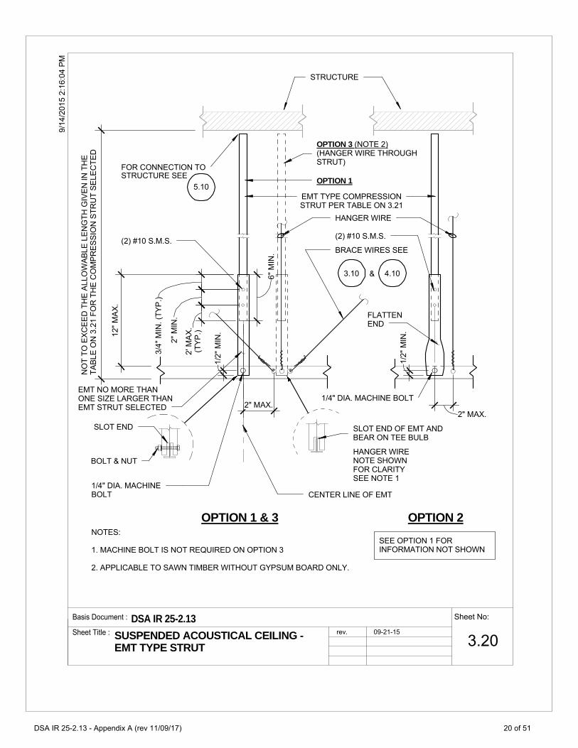
5.10
4.10
FLATTENEND
EMT NO MORE THANONE SIZE LARGER THANEMT STRUT SELECTED
SLOT END OF EMT ANDBEAR ON TEE BULB
1/4" DIA. MACHINE BOLT
FOR CONNECTION TO
EMT TYPE COMPRESSIONSTRUT PER TABLE ON 3.21
STRUCTURE
STRUCTURE SEE
HANGER WIRE
BRACE WIRES SEE
(2) #10 S.M.S.
HANGER WIRENOTE SHOWNFOR CLARITYSEE NOTE 1
OPTION 1 & 3 OPTION 2
(2) #10 S.M.S.
2" MAX.
3/4
"M
IN.(
TY
P.)
2"
MIN
.
6"
MIN
.
12"
MA
X.
.
(TY
P.)
2'M
AX
.
1/4" DIA. MACHINEBOLT
SEE OPTION 1 FORINFORMATION NOT SHOWN
3.10 &
NO
TT
OE
XC
EE
DT
HE
ALL
OW
AB
LEL
EN
GT
HG
IVE
NIN
TH
ET
AB
LEO
N3
.21
FO
RT
HE
CO
MP
RE
SS
ION
ST
RU
TS
ELE
CT
ED
1/2
"M
IN.
1/2
"M
IN.
SLOT END
BOLT & NUT
OPTION 1
OPTION 3 (NOTE 2)(HANGER WIRE THROUGHSTRUT)
2" MAX.
CENTER LINE OF EMT
NOTES:
1. MACHINE BOLT IS NOT REQUIRED ON OPTION 3
2. APPLICABLE TO SAWN TIMBER WITHOUT GYPSUM BOARD ONLY.
Sheet No:Basis Document :
Sheet Title :
DSA IR 25-2.13rev. 09-21-15
9/1
4/2
015
2:16
:04
PM
3.20SUSPENDED ACOUSTICAL CEILING -EMT TYPE STRUT
DSA IR 25-2.13 - Appendix A (rev 11/09/17)
20 of 51

3/1
0/2
01
7 1
1:3
4:4
3 A
M
5'-0"
6'-10"
8'-0"
8'10"
10'-10"
CHANNEL COMPRESSION STRUT MAXIMUM LENGTH
250S125-33
250S137-33
362S137-33
250137-43
400S137-43
3'-11"
6'-4"
9'-9"
12'-9"
14'-9"
EMT COMPRESSION STRUT MAXIMUM LENGTH
1/2" DIAMETER EMT (0.042" WALL THICKNESS)
18'-10"
3/4" DIAMETER EMT (0.049" WALL THICKNESS)
1" DIAMETER EMT (0.057" WALL THICKNESS)
1 1/4" DIAMETER EMT (0.065" WALL THICKNESS)
1 1/2" DIAMETER EMT (0.065" WALL THICKNESS)
2" DIAMETER EMT (0.065" WALL THICKNESS)
COMPRESSION STRUT TABLE
Basis Document : DSA IR 25-2.13 Sheet No:
3.21 Sheet Title :
COMPRESSION STRUT TABLE rev. 09-21-15
rev.
DSA IR 25-2.13 - Appendix A (rev 11/09/17)
21 of 51

3"
MA
X. 1/2
"T
YP
9/
/5
22
11
16::
00
44
PM
4.11
4.11
3 TURNS @ HANGER WIRE TYPICAL @ EACH END
4 TURNS @ BRACE WIRES TYP. @ EACH END
FOR CONNECTION TO STRUCTURE SEE CONNECTION MATRIX ON
FOR CONNECTION TO STRUCTURE SEE CONNECTION MATRIX ON
HANGER WIRE
BRACING WIRE
1 1/2" MAX.
10° TO 45°
U.N.O. 1/2" MAX.
1/2" MAX. U.O.N.
#12 GAGE WIRE
#12 GAGE WIRE
1/2" TYP
Basis Document : DSA IR 25-2.13 Sheet No:
4.10Sheet Title : HANGER AND BRACING WIRE
CONNECTION - TYPICAL WIRE TURNS
rev. 09-21-15
DSA IR 25-2.13 - Appendix A (rev 11/09/17)
22 of 51

9/
/5
22
11
16::
00
44
PM
CONCRETE OVER METAL DECK
CONCRETE SLAB, BEAM, OR JOIST
STRUCTURAL STEEL
METAL STUD WALL
SAWN TIMBER
STRUCTURAL CONDITION OF FLOOR/ ROOF ABOVESUSPENDED CEILING
WOOD I JOIST
WOOD CHORD TRUSS
METAL DECK
OPEN WEB STEEL JOIST
4.21
4.22
4.23
4.24
4.25, 4.29
APPLICABLE HANGER WIRE
DETAIL
4.26
4.27, 4.29
4.20
4.28, 4.29
4.31
4.32
4.33
4.34
4.35
APPLICABLE BRACING WIRE
DETAIL
4.36, 4.37
4.38, 4.29
4.30
4.39, 4.29
Basis Document : DSA IR 25-2.13 Sheet No:
4.11Sheet Title : HANGER AND BRACING WIRE
CONNECTION MATRIX
rev. 09-21-15
DSA IR 25-2.13 - Appendix A (rev 11/09/17)
23 of 51

94
//2
21
116:
:0
05
5P
M
NOTES:
1. REFER TO 4.10 FOR ADDITIONAL DETAILS.
.
METAL DECK (20 GA MIN.)
INSULATION OVER METAL DECK
4.10
#3 x 12" REBAR
HANGER WIRE-TIE TO #3 REBAR WITH THREE WRAPS AROUND REBAR AND ONE WRAP AROUND WIRE
Basis Document : DSA IR 25-2.13 Sheet No:
4.20Sheet Title : HANGER WIRE CONNECTION TO METAL
DECK
rev. 09-21-15
DSA IR 25-2.13 - Appendix A (rev 11/09/17)
24 of 51

94
//2
21
116:
:0
05
5P
M
NOTES:
1. REFER TO 4.10 FOR ADDITIONAL DETAILS.
2. POST INSTALLED ANCHORS TO BE PLACED NO MORE THAN 1" OFFSET FROM CENTERLINE OF DECK LOW FLUTE
3. TEST POST INSTALLED ANCHORS IN ACCORDANCE WITH CEILING NOTE 5.01.
L BOLT & FLUTE (SEE NOTE 3)
LIGHTWEIGHT OR NORMAL WEIGHT CONCRETE
12GA x 1" WIDE CEILING CLIP MIN.
3/8" DIA. EXPANSION ANCHORS
OPTION 1
C
4.101/2" MAX.
OPTION 2
STEEL DECK, 20GA MIN.
METAL DECK (20 GA MIN.)
[PAF-RDP TO SPECIFY DIA.AND MIN. EMBEDMENT. 0.145" DIAMETER MIN. AND 1 1/4" EMBEDMENT MIN.]
L 1-1/2"x 1-1/2"x 12 GA
OPTION 3
4.10
LIGHTWEIGHT OR NORMAL WEIGHT CONCRETE
12GAx3/4" WIDE CEILING CLIP
4.10
3/4" MIN
[(RDP TO SPECIFY MIN.EMBEDMENT]
[PAF-RDP TO SPECIFY DIA.AND MIN. EMBEDMENT. 0.145" DIAMETER MIN. AND 1 1/4" EMBEDMENT MIN.]
Basis Document : DSA IR 25-2.13 Sheet No:
4.21Sheet Title : HANGER WIRE CONNECTION TO
CONCRETE OVER METAL DECK
rev. 09-21-15
DSA IR 25-2.13 - Appendix A (rev 11/09/17)
25 of 51
94
//2
21
116:
:0
05
5P
M
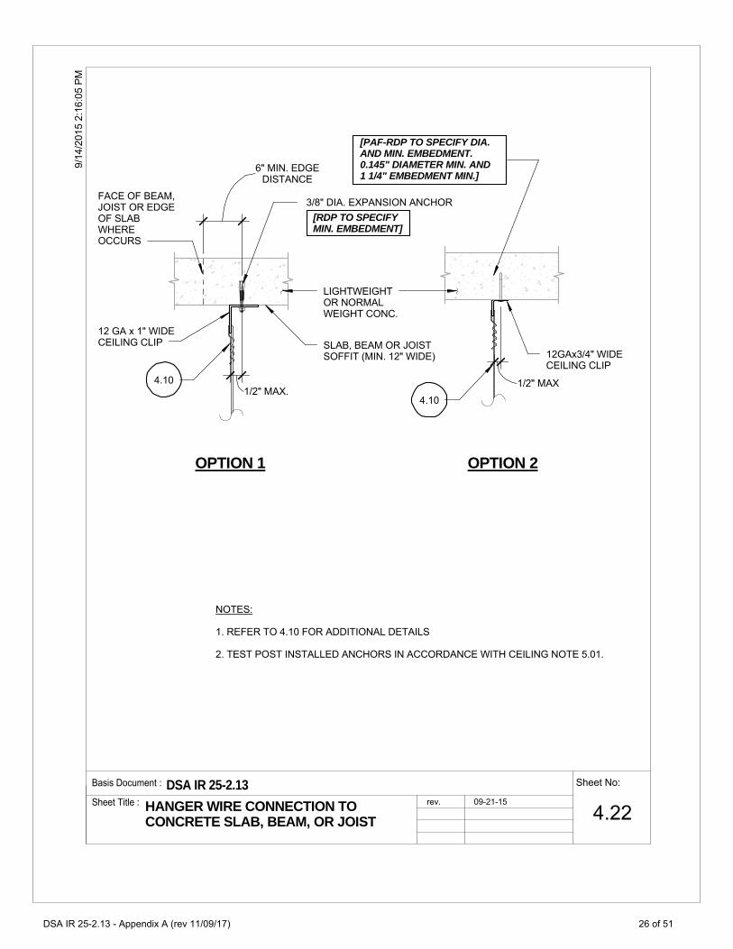
4.10
LIGHTWEIGHT OR NORMAL WEIGHT CONC.
12 GA x 1" WIDE CEILING CLIP
3/8" DIA. EXPANSION ANCHOR
SLAB, BEAM OR JOIST SOFFIT (MIN. 12" WIDE)
FACE OF BEAM, JOIST OR EDGE OF SLAB WHERE OCCURS
OPTION 1
DISTANCE 6" MIN. EDGE
1/2" MAX.
OPTION 2
12GAx3/4" WIDE CEILING CLIP
NOTES:
1. REFER TO 4.10 FOR ADDITIONAL DETAILS
2. TEST POST INSTALLED ANCHORS IN ACCORDANCE WITH CEILING NOTE 5.01.
4.10
1/2" MAX
[RDP TO SPECIFYMIN. EMBEDMENT]
[PAF-RDP TO SPECIFY DIA.AND MIN. EMBEDMENT. 0.145" DIAMETER MIN. AND 1 1/4" EMBEDMENT MIN.]
Basis Document : DSA IR 25-2.13 Sheet No:
4.22Sheet Title : HANGER WIRE CONNECTION TO
CONCRETE SLAB, BEAM, OR JOIST
rev. 09-21-15
DSA IR 25-2.13 - Appendix A (rev 11/09/17)
26 of 51

94
//2
21
116:
:0
05
5P
M
L1-1/2"x 1-1/2"x 12 GA x 0'-2" CLIP
STRUCTURAL STEEL
HANGER WIRE
FIRE PROOFING
NOTES :
1. BEAM FLANGE THICKNESS SHALL NOT BE LESS THAN 3/16".
2. RDP IN RESPONSIBLE CHARGE, IOR AND CONTRACTOR SHALL VERIFY THAT NO PAF IS INSTALLED IN THE PROTECTED ZONE OF ANY STEEL MEMBER. SEE ANSI/AISC 341-10
3. REFER TO 4.10 FOR ADDITIONAL DETAILS
1/2" MAX
[PAF-RDP TOSPECIFY DIAMETER, 0.145" DIA. MIN.]
Basis Document : DSA IR 25-2.13 Sheet No:
4.23Sheet Title : HANGER WIRE CONNECTION TO
STRUCTURAL STEEL
rev. 09-21-15
DSA IR 25-2.13 - Appendix A (rev 11/09/17)
27 of 51

94
//2
21
116:
:0
05
5P
M362S137-33 MIN. BACKING STUD. SPAN 2 WALL STUDS MINIMUM. FASTEN BACKING TO WALL STUDS USING (2) #10X1-1/4" SMS AT EACH STUD.
1"x1"x12GAx3/4" CLIP ANGLE. FASTEN TO BACKING STUD USING #10 X 1-1/4" SHEET METAL SCREW.
4.10
NOTES:
1. THIS IS APPLIED FOR PERIMETER WIRE ATTACHEMENT OR WHERE OBSTRUCTION PREVENTS ATTACHMENT TO STRUCTURE ABOVE
1
6 MIN.
1
6
1"x1"x12GAx3" CLIP ANGLE
2-#10 S.M.S. @ 2" O.C.
WALL STUD PER RDP 20 GA MIN
1 LAYER OF GYP. BD.
4.10
WALL STUD PER RDP 20 GA MIN
GYP. BD.
(2) #10 SMS TO FRAMING
1"x1"x12GAx3/4" CLIP ANGLE
4.10
A. "DIRECT" (FOR NOTES SEE "B" "THRU GYP.)
B. "THRU GYP" 1
OPTION 1 OPTION 2
OPTION 3
(1) #10 SMS
6 MIN.
Basis Document : DSA IR 25-2.13 Sheet No:
4.24Sheet Title : HANGER WIRE CONNECTION TO METAL
STUD WALL
rev. 09-21-15
DSA IR 25-2.13 - Appendix A (rev 11/09/17)
28 of 51

.N
PE
ER
AT
TIO
NN
-
11/
2"M
IN.
1"
MI
2"
MIN
.
94
//2
21
116:
:0
05
5P
M
GYP. BOARD WHERE OCCURS (SEE NOTE 1)
2x MIN.
EQ. EQ.
THREE 1-1/2" X 9 GA. STAPLES OR 3-STRONGHOLD "J" NAILS AT EACH WIRE LOOP
JOIST OR RAFTER
HANGER WIRE
4.29
HANGER WIRE
1/4" DIA. DRILLED HOLE
NOTE:
(1) WHEN FIRE RATED GYP. BOARD IS INSTALLED ON THE BOTTOM FLANGES, USE SCREW EYES W/ SUFFICIENT LENGTH TO AVOID DAMAGING THE FIRE RATED GYP.
BOARD AND MEET MIN. PENETRATION.
1/4" DIA. CLOSED EYE SCREW
4.10 TYP.
Basis Document : DSA IR 25-2.13 Sheet No:
4.25Sheet Title : HANGER WIRE CONNECTION TO SAWN
TIMBER
rev. 09-21-15
DSA IR 25-2.13 - Appendix A (rev 11/09/17)
29 of 51

PE
ER
AT
TIO
NN
-
11/
2"M
IN.
94
//2
21
116:
:0
05
5P
M
1/4" DIA. CLOSED SCREW EYE WITH 1-1/2" MIN. PENETRATION AT BOTTOM FLANGE
4.10
1" MINIMUM.
NOTE:
(1) WHEN FIRE RATED GYP. BOARD IS INSTALLED ON THE BOTTOM FLANGES, USE SCREW EYES W/ SUFFICIENT LENGTH TO AVOID DAMAGING THE FIRE RATED GYP.
BOARD AND MEET MIN. PENETRATION.
Basis Document : DSA IR 25-2.13 Sheet No:
4.26Sheet Title : HANGER WIRE CONNECTION TO
WOOD I JOIST
rev. 09-21-15
DSA IR 25-2.13 - Appendix A (rev 11/09/17)
30 of 51

94
//2
21
116:
:0
05
5P
M
TRUSS WEB MEMBER
TRUSS CHORD MEMBER
HANGER WIRE SADDLE
4.294.10
Basis Document : DSA IR 25-2.13 Sheet No:
4.27Sheet Title : HANGER WIRE CONNECTION TO WOOD
CHORD TRUSS
rev. 09-21-15
DSA IR 25-2.13 - Appendix A (rev 11/09/17)
31 of 51

94
//
52
21
11:
:0
06
6P
M
JOIST WEB MEMBER
JOIST CHORD MEMBER
HANGER WIRE SADDLE
4.294.10
Basis Document : DSA IR 25-2.13 Sheet No:
4.28Sheet Title : HANGER WIRE CONNECTION TO OPEN
WEB STEEL JOIST
rev. 09-21-15
DSA IR 25-2.13 - Appendix A (rev 11/09/17)
32 of 51

94
//
52
21
11:
:0
06
6P
M
SADDLE TIE HAS DOUBLE LOOP AT SUPPORT
#12 GAGE HANGER WIRES (3) TIGHT TURNS WITHIN 3", AT BRACE WIRE PROVIDE (4) TIGHT TURNS WITHIN 1 1/2".
WHEN MULTILE SADDLE TIES ARE REQUIRED THEY SHALL ALTERNATE BACK AND FORTH TO PREVENT TWISTING
TYPICAL SADDLE TIE DETAIL
MAIN CHANNEL SHOWN (WOOD FRAMING SIMILAR)
SADDLE TIE REQUIRED FOR ALL WIDTHS GREATER THAN 1/4"
HANGER WIRE CONDITION SHOWN. BRACE WIRE CONDITION SIMILAR
Basis Document : DSA IR 25-2.13 Sheet No:
4.29Sheet Title : TYPICAL SADDLE TIE DETAIL rev. 09-21-15
DSA IR 25-2.13 - Appendix A (rev 11/09/17)
33 of 51

94
//
52
21
11:
:0
06
6P
M
NOTES:
1. IF SELF-TAPPING SCREWS ARE USED WITH CONCRETE FILL, SET SCREWS BEFORE PLACING CONCRETE.
.
METAL DECK (20 GA MIN.)
(2) #8 x 1/2" SELFTAPPING SCREWS
STEEL STRAP 3" WIDE x 4" LONG x 12 GA. MIN., BEND
TO ALIGN WITH WIRE
INSULATION OVER METAL DECK
BRACING WIRE
4.10
Basis Document : DSA IR 25-2.13 Sheet No:
4.30Sheet Title : BRACING WIRE CONNECTION AT
METAL DECK
rev. 09-21-15
DSA IR 25-2.13 - Appendix A (rev 11/09/17)
34 of 51

94
//
52
21
11:
:0
06
6P
M
MIN 5/8" DIA EXPANSION ANCHOR @ BRACING, TYP
NOTES:
1. TEST POST INSTALLED ANCHORS IN ACCORDANCE WITH CEILING NOTE 5.02
2. REFER TO 4.10 FOR ADDITIONAL DETAILS
3. POST INSTALLED ANCHORS TO BE PLACED NO MORE THAN 1" OFFSET FROM CENTERLINE OF DECK LOW FLUTE.
1 1/2"x 1 1/2"x12GA x2" CEILING CLIP, TYP
LIGHTWEIGHT OR NORMAL WEIGHT CONCRETE
4.10
TYP 3/4" MIN
(2) 3/8" DIA EXPANSION ANCHORS
LIGHTWEIGHT OR NORMAL WEIGHT CONCRETE
OPTION 1
OPTION 2
1-1/2"x1-1/2"x12GA
4.10
1/2" MAX.
[RDP TO SPECIFY MIN. EMBEDMENT]
[RDP TO SPECIFY MIN. EMBEDMENT]
Basis Document : DSA IR 25-2.13 Sheet No:
4.31Sheet Title : BRACING WIRE CONNECTION TO
CONCRETE OVER METAL DECK
rev. 09-21-15
DSA IR 25-2.13 - Appendix A (rev 11/09/17)
35 of 51

10/
22/2
015
9:44
:17
AM
4.10
MIN 5/8" DIA EXPANSION ANCHOR @ BRACING WIRE TYP.
1 1/2" x 1 1/2"x12 GA x 2" CEILING CLIP
LIGHTWEIGHT OR NORMAL WEIGHT CONCRETE SLAB. DO NOT CONNECT BRACING WIRE TO JOIST OR BEAM.
1/2" (MAX)
NOTES:
1. TEST POST INSTALLED ANCHORS IN ACCORDANCE WITH CEILING NOTE 5.02
2. REFER TO 4.10 FOR ADDITIONAL DETAILS
[ RDP TO SPECIFY MIN. EMBEDMENT]
TYP.
6" MIN.
EDGE OF SLAB
Basis Document : DSA IR 25-2.13 Sheet No:
4.32Sheet Title : BRACING WIRE CONNECTION TO
CONCRETE SLAB, BEAM OR JOIST
rev. 09-21-15
DSA IR 25-2.13 - Appendix A (rev 11/09/17)
36 of 51

94
//
52
21
11:
:0
06
6P
M
[(3) PAF - RDP TOSPECIFY DIAMETER, 0.145" DIA. MIN. ]
BRACING WIRE
FIRE PROOFING
NOTES :
1. BEAM FLANGE THICKNESS SHALL NOT BE LESS THAN 3/16".
2.RDP IN RESPONSIBLE CHARGE, IOR, AND CONTRACTOR SHALL VERIFY THAT NO PAF IS INSTALLED IN THE PROTECTED ZONE OF ANY STEEL MEMBER. SEE ANSI/AISC 341-10
3. REFER TO 4.10 FOR ADDITIONAL DETAILS
1/2" MAX.
2" X 2" X 2" LONG X 12 GA. CLIP
Basis Document : DSA IR 25-2.13 Sheet No:
4.33Sheet Title : BRACING WIRE CONNECTION TO
STRUCTURAL STEEL
rev. 09-21-15
DSA IR 25-2.13 - Appendix A (rev 11/09/17)
37 of 51

3/1
0/2
01
7 1
1:3
4:4
3 A
M
METAL STUD PER RDP 20 GA MIN.
1 LAYER OF GYP. BD., MAX.
600S137-54 SPAN (2) WALL STUDS MINIMUM. CONNECT 600S TO EACH WALL STUD PER SCHEDULE BELOW
1-1/2"x1-1/2"x12GAx1" CLIP ANGLE W/ (2) #10x1-1/4" SMS (SEE NOTE 1)
1/2
" M
AX
4.10
WALL STUD GAUGE
CONNECTION TO WALL STUD
(WITH GYP. BD.)
CONNECTION TO WALL STUD
(WITHOUT GYP. BD.)
(5) #10x1-1/4" SMS (3) #10x1-1/4" SMS
(2) #10x1-1/4" SMS
20 GAUGE
18 GAUGE (4) #10x1-1/4" SMS
NOTES:
1. THE CLIP ANGLE CAN BE ATTACHED DIRECTLY TO THE WALL STUD FLANGE PROVIDED BOTH OF THE FOLLOWING CONDITIONS ARE MET: - THE WALL STUD IS 18 GA MIN. AND CAPABLE OF SUPPORTING THE BRACE FORCE. - THE BRACE WIRE ALIGNS WITH THE WALL STUD WEB.
Basis Document : DSA IR 25-2.13 Sheet No:
4.34 Sheet Title :
BRACING WIRE CONNECTION TO
METAL STUD WALL
rev. 09-21-15
rev.
DSA IR 25-2.13 - Appendix A (rev 11/09/17)
38 of 51

1"
MIN
.
3"
MA
X.
94
//
52
21
11:
:0
06
6P
M
1/4" DIA. CLOSED SCREW EYE. INSTALL IN THE DIRECTION OF THE BRACE WIRE
BLOCKING FASTEN TO JOIST w/ 1-1/2" X 1-1/2" X 18 GA.
CLIP AND (4) 8d X 1-1/2" NAILS EACH SIDE AND EACH END
.
1-1/2" MIN. PENETRATION
THREE 1-1/2" X 9 GA. STAPLES OR 3-STRONGHOLD "J" NAILS AT EACH WIRE LOOP
BRACING WIRE 2X BLKG. w/ 2-16d COMMON NAILS AT EACH END
4.10
THREE 1-1/2" X 9 GA. STAPLES OR 3-STRONGHOLD "J" NAILS AT EACH WIRE LOOP
JOIST OR RAFTER
BRACING WIRE
JOIST OR RAFTER
BRACING WIRE
1/4" DIA. SCREW EYE w/ FULL THREAD EMBEDMENT (1-1/2" MIN.) INSTALL IN DIRECTION OF WIRE
Basis Document : DSA IR 25-2.13 Sheet No:
4.35Sheet Title : BRACING WIRE CONNECTION TO SAWN
TIMBER
rev. 09-21-15
DSA IR 25-2.13 - Appendix A (rev 11/09/17)
39 of 51

94
//
52
21
116:
:0
07
PM
1/4" DIA. SCREW EYE WITH 1-1/2" MIN. PENETRATION. ALIGN WITH BRACE WIRE
BRACE WIRE WITH 4 TIGHT TURNS
NOTE: (1) DO NOT INSERT SCREW EYES
PARALLEL TO LAMANATIONS. (2) WHEN FIRE RATED GYP. BOARD
IS INSTALLED ON THE BOTTOM FLANGES, USE SCREW EYES
w/ SUFFICIENT LENGTH TO AVOID DAMAGING THE FIRE RATED GYP. BOARD AND MEET MINIMUM PENETRATION.
PLYWOOD FLOOR/ROOF SHEATHING
CEILING BRACING BLOCKING ATTACHED TO JOIST BOTTOM FLANGE. SEE BELOW
WOOD I-JOIST
FULL DEPTH JOIST BLOCKING
4.10
Basis Document : DSA IR 25-2.13 Sheet No:
4.36Sheet Title : BRACE WIRE CONNECTION TO
WOOD I - JOIST
rev. 09-21-15
DSA IR 25-2.13 - Appendix A (rev 11/09/17)
40 of 51

94
//
52
21
116:
:0
07
PM
1/4" DIA. CLOSED SCREW EYE WITH 1-1/2" MIN. PENETRATION. ALIGN WITH BRACE WIRE
BRACE WIRE WITH 4 TIGHT TURNS
NOTE: (1) DO NOT INSERT SCREW EYES
PARALLEL TO LAMINATIONS. (2) WHEN FIRE RATED GYP. BOARD
IS INSTALLED ON THE BOTTOM FLANGES, USE SCREW EYES
w/ SUFFICIENT LENGTH TO AVOID DAMAGING THE FIRE RATED GYP. BOARD AND MEET MIN. PENETRATION. 1" CLR.
PLYWOOD FLOOR/ROOF SHEATHING
CEILING BRACING WIRE ATTACHED TO JOIST BOTTOM FLANGE. SEE BELOW
4.10
BRIDGING OR FULL DEPTH JOIST BLOCKING WITHIN 24" OF BRACING WIRE CONNECTION. PROVIDE NEW IF NONE EXISTS.
WOOD I-JOIST
ADD 2-1/2" X 20 GA. STUD* w/ (1) #10 X 1" WOOD SCREW TO EACH OF 3 JOISTS. PLACE STUD FLAT AND WITHIN 6" OF BRACING WIRE.
*ALTERNATE: 2 X 4 FLAT w/ 1-10d OR 1-#10 X 3" SCREW TO EACH OF 3 TRUSS BOTTOM FLANGES
Basis Document : DSA IR 25-2.13 Sheet No:
4.37Sheet Title : BRACE WIRE CONNECTION TO
WOOD I - JOIST
rev. 09-21-15
DSA IR 25-2.13 - Appendix A (rev 11/09/17)
41 of 51

94
//
52
21
116:
:0
07
PM
TRUSS WEB MEMBER
TRUSS CHORD MEMBER
BRACE WIRE SADDLE TIE SEE
4.29
NOTES:
1. BRACE WIRE SHALL ALIGN PARALLEL WITH THE TRUSS BOTTOM CHORD
Basis Document : DSA IR 25-2.13 Sheet No:
4.38Sheet Title : BRACE WIRE CONNECTION TO WOOD
CHORD TRUSS
rev. 09-21-15
DSA IR 25-2.13 - Appendix A (rev 11/09/17)
42 of 51

94
//
52
21
116:
:0
07
PM
JOIST WEB MEMBER
JOIST CHORD MEMBER
BRACE WIRE SADDLE TIE SEE
4.29
NOTES:
1. BRACE WIRE SHALL ALIGN PARALLEL WITH THE TRUSS BOTTOM CHORD
Basis Document : DSA IR 25-2.13 Sheet No:
4.39Sheet Title : BRACE WIRE CONNECTION TO
OPEN-WEB STEEL JOIST
rev. 09-21-15
DSA IR 25-2.13 - Appendix A (rev 11/09/17)
43 of 51

94
//
52
21
116:
:0
07
PM
CONCRETE OVER METAL DECK 5.21
CONCRETE SLAB, BEAM, OR JOIST 5.30
STRUCTURAL STEEL 5.40
5.50
5.60
SAWN TIMBER WITH GYPSUM BOARD
SAWN TIMBER WITHOUT GYPSUM BOARD
STRUCTURAL CONDITION OF FLOOR / ROOF ABOVE COMPRESSION STRUT
APPLICABLE DETAIL
METAL DECK 5.20
Basis Document : DSA IR 25-2.13 Sheet No:
5.10Sheet Title : COMPRESSION STRUT CONNECTION
TO STRUCTURE - CONNECTION MATRIX
rev. 09-21-15
DSA IR 25-2.13 - Appendix A (rev 11/09/17)
44 of 51

INSULATION OVER METAL DECK #12 S.M.S
94
//
52
21
116:
:0
07
PM
METAL DECK (20 GA. MIN.)
3/4" MIN(2) #12 S.M.S. (2) #10 S.M.S
L 2" x 2" x 12 GA.L 2" x 2" x 12 GA. x 0'-8" (2) #10 S.M.S
OPTION 1 OPTION 2
CHANNEL STRUT INSULATION OVER METAL DECK
METAL DECK (20 GA. MIN.)
L 2" x 2" x 12 GA.(2) #12 S.M.S. (2) #10 S.M.S. x 0'-8"
(2) #12 S.M.S. (2) #10 S.M.S
FLATTEN END
SLOT ENDPLACE TIGHT TO CLIP OF TUBEPLACE TIGHT TOOR STRUCTURE
CLIP OR STRUCTURE
L 2" x 2" x 12 GA. x 0'-8"
OPTION 1 OPTION 2
TUBE STRUT Sheet No:Basis Document : DSA IR 25-2.13
rev. 09-21-15Sheet Title : STRUT CONNECTION TO METAL DECK 5.20
DSA IR 25-2.13 - Appendix A (rev 11/09/17)
45 of 51

LIGHTWEIGHT OR NORMAL WEIGHT CONCRETE
3/8" DIA. EXPANSION ANCHOR.
[RDP TO SPECIFYMIN. EMBEDMENT]
FLATTEN END
PLACE TIGHT TO CLIP OR STRUCTURE
94
//
52
21
116:
:0
07
PM
OPTION 1 NOTES: 1. POST INSTALLED ANCHORS TO
BE PLACED NO MORE THAN 1" OFFSET FROM CENTERLINE OF DECK LOW FLUTE
2. TEST POST INSTALLED ANCHORS IN ACCORDACE WITH CEILING NOTE 5.01
Basis Document : DSA IR 25-2.13
LIGHTWEIGHT 3/8" DIA. EXPANSION ANCHOR OR NORMAL [RDP TO SPECIFYWEIGHT CONCRETE MIN. EMBEDMENT]1"
CHANNEL STRUT
3/8" DIA. EXPANSION ANCHOR @ CENTER 3/4" MINOF FLUTE
2" [RDP TO SPECIFY
L 1-1/2 x 1-1/2 x 12 GA.MIN. EMBEDMENT] (2) #10 S.M.S
CUT FLANGES3 7/8" MIN. AND BEND
OPTION 1 OPTION 2
TUBE STRUT Sheet No:
rev. 09-21-15Sheet Title : STRUT CONNECTION TO CONCRETE 5.21OVER METAL DECK
3/4"
(2) #10 S.M.S.
3/8" DIA. EXPANSION ANCHOR.
[RDP TO SPECIFYMIN. EMBEDMENT]
PLACE TIGHT TO CLIP OR STRUCTURE
L1-1/2"x 1-1/2"x 12 GA. x 0'-2"
3/4"
L 1-1/2 x 1-1/2 x 12 GA. x 0'-2"
(2) #10 S.M.S
SLOT END OF TUBE
OPTION 2
DSA IR 25-2.13 - Appendix A (rev 11/09/17)
46 of 51

6" MIN. EDGE DISTANCE LIGHTWEIGHT OR
FACE OF BEAM, SLAB EDGE ORNORMAL WEIGHT JOIST WHERE OCCUR,CONCRETE, TYP TYPICAL
1"
94
//
52
21
116:
:0
07
PM
3/8" EXPANSION ANCHOR [ RDP TO SPECIFY MIN. EMBEDMENT]
2"
CUT FLANGES AND BEND
CHANNEL STRUT LIGHTWEIGHT OR NORMAL WEIGHT LIGHTWEIGHT CONCRETE, TYP. 3/8" EXPANSION ANCHOR OR NORMAL
WEIGHT[ RDP TO SPECIFY MIN.L 1-1/2 x 1-1/2 x CONCRETE, TYP.EMBEDMENT]3/4" 3/4" 12GA. x 2" CLIP
(2) #10 S.M.S.
3/8" EXPANSION FLATTEN ENDANCHOR
L 1-1/2"x 1-1/2"x[ RDP TO SPECIFY MIN. 10GA. x 2" CLIPEMBEDMENT] (2) #10 x 2" S.M.S.
PLACE TIGHT TO CLIP PLACE TIGHT OR STRUCTURE SLOT END OF TUBE TO CLIP OR
TO RECEIVE CLIP STRUCTURE
OPTION 1 OPTION 2 NOTES: 1. TEST POST INSTALLED
ANCHORS IN ACCORDANCE WITH CEILING NOTE 5.01 TUBE STRUT
Sheet No:Basis Document : DSA IR 25-2.13 rev. 09-21-15Sheet Title : STRUT CONNECTION TO CONCRETE 5.30SLAB, BEAM, JOIST SOFFIT
DSA IR 25-2.13 - Appendix A (rev 11/09/17)
47 of 51

94
//
52
21
116:
:0
08
PM
FIRE PROOFING
[ (2) PAF - RDP TOSPECIFY DIAMETER-0.145" DIAMETER MIN.]
2"
CUT FLANGES AND BEND
CHANNEL STRUT [ (2) PAF - RDPTO SPECIFY FIRE PROOFINGDIAMETER -0.145" DIAMETER [ (2) PAF - RDP TOMIN.] SPECIFY DIAMETER -
0.145" DIAMETER MIN.]
L 1-1/2"x 1-1/2"x 12GA. x 2" ANGLE
L1-1/2 x 1-1/2x 10GA. x 2" ANGLE
(2) #10 S.M.S.
SLOT END OF TUBE
PLACE TIGHT TO CLIP OR STRUCTURE
OPTION 1 OPTION 2
TUBE STRUT
NOTES:
1. STRUCTURAL STEEL MEMBER SHALL NOT BE LESS THAN 3/16".
2. RDP IN RESPONSIBLE CHARGE, I.O.R. AND CONTRACTOR SHALL VERIFY THAT NO PAF IS INSTALLED IN THE PROTECTED ZONE OF ANY STEEL MEMBER, SEE ANSI/AISC 341-10.
3. REFER TO 5.20 AND 5.30 FOR ADDITIONAL INFORMATION.
Basis Document : DSA IR 25-2.13 rev. 09-21-15Sheet Title : STRUT CONNECTION TO STRUCTURAL
STEEL
FIRE PROOFING
(2) #10 x 2" S.M.S.
PLACE TIGHT TO CLIP OR STRUCTURE
Sheet No:
5.40
DSA IR 25-2.13 - Appendix A (rev 11/09/17)
48 of 51

NIM
2/1.
P
YT,
NOI
AR
E
EE
RA
ION
N,
TT
TY
PP
1
1/2"
MIN
.
EN
TT
P1
"
EE
RA
ION
N,
TT
TY
PP
1
1/2"
MIN
.
EE
RA
ION
N,
TT
TY
PP
1
1/2"
MIN
94
//
52
21
116:
:0
08
PM
L STRUT
CUT FLANGES AND BEND
PLACE TIGHT TO CLIP OR STRUCTURE
1/4" DIA. LAG SCREW
SLOT END
2x4 STRUT
L-1-1/2"x1-1/2"x 12GA. x 0'-2" CLIP (SEE NOTE 2)
GYP. BOARD
FASTEN STRUT TO 2x4 IN LIEU OF RAFTER/ JOIST
1/4" DIA. LAG SCREW
1/4" DIA. LAG SCREW
(2)#10 x 2" S.M.S. THRU BOTH WALLS OF EMT
1/4" DIA. LAG SCREW
(2) #10 S.M.S. OPTIONAL
ORIENTATION
CONNECT USING OPTION 1 ON THIS SHEET
OPTION 1
CHANNEL STRUT
OPTION 1 OPTION 2
TUBE STRUT
C
PLACE TIGHT TO CLIP OR STRUCTURE
NOTES:
1. WEB OF CHANNEL TO BEAR WITHIN WIDTH OF THE WOOD MEMBER.
2. FOR ANGLE ORIENTED IN THE STANDARD POSITION, VERTICAL LEG TO FALL WITHIN THE WIDTH OF THE WOOD MEMBER.
L-1-1/2"x1-1/2"x 10GA. x 2" CLIP (SEE NOTE 2)
EQ EQEQ EQ
OPTION 2
1" MIN
EQ. EQ.
SEE NOTE 1
Basis Document : DSA IR 25-2.13 Sheet No:
5.50Sheet Title : STRUT CONNECTION TO SAWN TIMBER
WITH GYPSUM BOARD
rev. 09-21-15
DSA IR 25-2.13 - Appendix A (rev 11/09/17)
49 of 51

N
IM
2/1N
OI
TA
RE
P
2
11/
2"M
IN.
M
N
IN
"
PE
ER
AT
TIO
NN
1
1/2"
MI
ET
N1"9
4/
/5
22
11
16::
00
8P
M
L STRUT
2"
CUT FLANGES AND BEND
PLACE TIGHT TO STRUCTURE
WIRE WITHIN
1/4"DIA. CLOSED EYE SCREW
SLOT END OF TUBE
2x4 FLAT STRUT
1/4" DIA. LAG SCREW
(4) 1/4" DIA. LAG SCREWS
1/4"DIA. LAG SCREW IN CENTER OF JOIST, TYP.
1/4"DIA. LAG SCREW IN CENTER OF JOIST, TYP.
(2) #10 S.M.S.
1-1/2"x 1-1/2"x 12GA x 0'-2" CLIP (SEE NOTE 2)
(2) #10 S.M.S.
OPTION 2
CHANNEL STRUT
OPTION 1 OPTION 3OPTION 2
TUBE STRUT
OPTION 1
C
CONNECT USING OPTION 2 ON THIS SHEET
1 3/8"
PLACE TIGHT TO CLIP
L1-1/2" X 11/2" 12GA. BEARING PLATE MIN.
NOTES:
1. WEB OF CHANNEL TO BEAR WITHIN WIDTH OF WOOD MEMBER.
FASTEN STRUT TO 2x4 IN LIEU OF RAFTER/ JOIST
1-1/2"x 1-1/2"x 10GA x 2" CLIP (SEE NOTE 2)
. 1 1/2" MIN PENETRATION
. .1 1/2" MIN PENETRATION
1 1/2" MIN PENETRATION
OPTION 3
EQ. EQ.
SEE NOTE 1
2. VERTICAL LEG OF MEMBER TO FALL WITHIN THE WIDTH OF THE WOOD MEMBER.
3. SEE PAGE 5.50 FOR ADDITIONAL INFORMATION.
Basis Document : DSA IR 25-2.13 Sheet No:
5.60Sheet Title : STRUT CONNECTION TO SAWN TIMBER
WITHOUT GYPSUM BOARD
rev. 09-21-15
DSA IR 25-2.13 - Appendix A (rev 11/09/17)
50 of 51

94
//
52
21
116:
:0
08
PM
3 TURNS IN 3" TYPICAL @ EACH END
HANGER WIRE ONLY
HANGER WIRE
4 TURNS IN 1-1/2" TYPICAL @ EACH END
HANGER OR BRACE WIRE
BRACE OR HANGER WIRE
NOTES:
WIRE SPLICES ARE SHOWN LOOSELY TIED FOR ILLUSTRATIVE PURPOSES ONLY AND SHALL BE DRAWN TIGHT TO COMPLETE INSTALLATION WHEN CONSTRUCTED.
Basis Document : DSA IR 25-2.13 Sheet No:
6.10Sheet Title : CEILING WIRE SPLICES rev. 09-21-15
DSA IR 25-2.13 - Appendix A (rev 11/09/17)
51 of 51