iq gate systems
TRANSCRIPT

IQ Gate Systems www.iqgatesystems.com
IntelliSlide SL-G5 Installation And
MC4 Instruction Manual
UL 325/991 Compliant 1/2017

IQ Gate Systems Warranty Information
This document pertains to all IQ Gate Systems manufactured products. All products that are sold, but not manufactured by IQ Gate Systems are not covered under this warranty. The following warranty covers models including but not limited to:
IQ-50 / IntelliSwing IQ-50-H Series** IQ-500 / IntelliSwing SW-G5 IQ-500c IQ-5000 / IntelliSlide SL-G5 IQ-12B / IntelliPark Barrier Arm
IQ Gate Systems reserves the right to alter its warranty coverage and models including coverage duration without prior notification. Limited Warranty **IQ Gate Systems model IQ-50 / IntelliSwing IQ-50-H Series linear gate operator is covered by the following warranty for a period of two years (24 months) from the date of original purchase. IQ Control Boards sold independently of an IQ gate operator are only entitled to an 12 month warranty from the date of purchase by the original buyer. IQ Gate Systems new products, not including the IQ-50 linear actuator, are warranted to be free of defects in material or workmanship for a period of three years, (36 months), from the date of purchase. This warranty does not cover aesthetical defects in materials. This warranty extends only to wholesale customers who buy direct from IQ Gate Systems or through IQ Gate Systems normal distribution channels. This warranty also only covers and is extended to products that are manufactured by IQ Gate Systems. IQ Gate Systems does not warrant any products in any way to the end user consumer. Consumers must obtain warranty information from the selling dealer and/or installer as to the nature of the dealer’s warranty, if any. All contact to IQ Gate Systems from the end user consumer will be referred to the consumer’s selling dealer and/or installer. There are no obligations and/or liabilities on the part of IQ Gate Systems for consequential damages arising out of or in connection with use or performance of IQ Gate Systems products or other indirect damages with respect to loss of property, revenue, or profit, or cost of removal, installation, or reinstallation. Any use or change to IQ Gate Systems products not expressly approved by the manufacturer, and performed by an authorized dealer/installer will immediately void the warranty. All implied warranties, including warranties for marketability as well as implied warranties for suitability, are valid only until the warranty expires or is voided, whichever comes first.
This IQ Gate Systems Limited Warranty is in lieu of all other warranties express or implied and all IQ Gate Systems warranties are subject, but not limited, to the following conditions.
NEW PRODUCT POLICY
1. The products must be properly installed as specified; and maintained or used as intended. 2. Cause of product failure is not due to vandalism or malicious mischief, improper installation, abnormal physical or electrical stress, lightning, power surges, misuse, negligence, accidents, or Natural disasters. Normal “wear and tear” from use of equipment is not covered under warranty 3. Warranty is immediately null and void if the product has been altered, repaired, or modified without express written authorization from IQ Gate Systems Technical Department, with such authorization given only to manufacturer approved dealer/installers. 4. Under no circumstances will IQ Gate Systems honor warranty on any product found to have been altered, repaired, and/or modified by the end-user consumer.
! 2

5. IQ Gate Systems reserves the right to repair the product, or replace a warranted product with a like product of equal value in the event original product cannot be repaired. 6. Distributors and/or Dealer-Installer must first obtain a Return Merchandise Authorization (RMA) number from IQ Gate Systems Technical Department before returning any product to factory for repair, whether under warranty or not. No returns accepted without RMA. 7. Return Merchandise Authorization (RMA) numbers will not be issued to the end-user consumers. Consumers must contact their selling dealer-installer for any/all warranty issues. 8. Distributor and/or Dealer-Installer are responsible for all shipping charges, incl. freight and insurance fees, for products shipped to IQ Gate Systems repair center. 9. IQ Gate Systems warranty does not guarantee any product to be free of operation error or service interruption in any way during the course of daily product operation. 10. IQ Gate Systems is not responsible for time, travel, and/or labor costs of any distributor and/or dealer-installer, including but not limited to, any expenses to install, uninstall or reinstall hardware/software/firmware related to warranty issues, product enhancements, or product failures.
IQ GATE SYSTEMS NON-WARRANTY REPAIR LIMITED WARRANTY
NON-WARRANTY REPAIR POLICY IQ Gate Systems warrants repairs to be free of defects in material or workmanship for a period of three (3) months from the date of repair and invoice. This warranty extends only to wholesale customers who buy direct from IQ Gate Systems or through IQ Gate Systems normal distribution channels. Consumers must obtain warranty information from the selling dealer and/or installer as to the nature of the dealer’s warranty, if any. All contact to IQ Gate Systems from the end user consumer will be referred to the consumer’s selling dealer and/or installer. This IQ Gate Systems Limited Warranty is in lieu of all other warranties express or implied and all IQ Gate Systems warranties are subject, but not limited, to the following conditions. 1. The products must be properly re-installed as specified; and maintained or used as intended. 2. Cause of repaired product failure is not due to vandalism or malicious mischief, improper installation, abnormal physical or electrical stress, lightning, power surges, misuse, negligence, accidents, or Natural disasters. 3. Warranty is immediately null and void if the product has been altered, repaired, or modified without express written authorization from IQ Gate Systems Technical Department, with such authorization given only to manufacturer approved dealer/installers. 4. Under no circumstances will IQ Gate Systems honor warranty of any product found to have been altered, repaired, and/or modified by the end-user consumer. 5. IQ Gate Systems reserves the right to replace a previously repaired product with a like product of equal value in the event of repair failure, provided repair failure occurs within the specified warranty period. 6. Distributors and/or Dealer-Installer must first obtain a Return Merchandise Authorization (RMA) number from IQ Gate Systems Technical Department before returning any product to factory for non-warranty repair. No repair returns accepted without RMA. 7. Return Merchandise Authorization (RMA) numbers will not be issued to the end-user consumers. Consumers must contact their selling dealer-installer for any/all warranty issues. 8. Distributor and/or Dealer-Installer are responsible for all shipping charges, incl. freight and insurance fees, for products shipped to IQ Gate Systems repair center. 9. IQ Gate Systems warranty does not guarantee any product, new or repaired, to be free of operation error or service interruption in any way during the course of daily product operation 10. IQ Gate Systems is not responsible for time, travel, and/or labor costs of any distributor and/or dealer-installer, including but not limited to, any expenses to install, uninstall or reinstall hardware/software/firmware related to warranty issues, product enhancements, or product failures.
IMPORTANT REPAIR NOTE: IQ Gate Systems will perform a factory physical evaluation of all products submitted for repair at receipt of item, and reserves the right to decline repairs after said physical evaluation. In the event a returned product is deemed ineligible for repair; the product will be returned to sender via common carrier ground at IQ Gate Systems expense. NO RETURNS WILL BE REPAIRED, CREDITED, OR RETURNED WITHOUT THE RMA# THAT WAS ISSUED FOR THE MENTIONED PRODUCT FROM IQ GATE SYSTEMS.
! 3

!
IQ Gate Systems: IQ-5000 Installation IQ-5000 Capacities: Slide gates that are up to 1500 lbs and 35 feet in length
Important Safety Instructions WARNING – TO REDUCE THE RISK OF INJURY OR DEATH - READ AND FOLLOW ALL INSTRUCTIONS.
Never let children operate or play with gate controls. Keep the remote control away from children. Always keep people and objects away from the gate. NO ONE SHOULD CROSS THE PATH OF THE MOVING GATE. Test the gate operator monthly. The gate MUST reverse on contact with a rigid object or stop when an object activates the non-contact sensors. After adjusting the force or the limit of travel, retest the gate operator. Failure to adjust and retest the gate operator properly can increase the risk of injury or death. Use the emergency release only when the gate is not moving. Make sure that all power to the gate operator is off. KEEP GATES PROPERLY MAINTAINED. Read the owner’s manual. Have a qualified service person make repairs to gate hardware. The entrance is for vehicles only. Pedestrians must use separate entrance. SAVE THESE INSTRUCTIONS.
Warning: To reduce the risk of injury or death, please read the following:
1. Read, follow and understand all instructions 2. The automated gate is not for pedestrian use 3. Do not activate your gate operator unless it is in sight and you can determine that it will travel without
interfering with any objects or persons. Always keep people and objects away from the gate and its area of travel
4. Keep all access devices such as key switches, push buttons, and telephone entry systems away from the gate. The recommended distance is a minimum of 10 feet.
5. Make sure that all warning signs have been attached and that the operator has been installed correctly
6. If edges and photoelectric sensors have been installed, they should be tested for proper operation. 7. Keep gates properly maintained. Grease and lubricate all hinges and brackets to prevent binding and
unnecessary friction. 8. Have the operator tested and serviced by a qualified and experienced technician. The gate should
respond and reverse to all obstructions both inherently and externally 9. Disconnect the operator only when it is not in motion 10. DO NOT turn on the automatic close timer unless the gate is equipped with at least one non-contact
external obstruction sensor, e.g., a photo electric beam, a vehicle loop, etc.
! Warning: Do not install this gate operator if you don’t have experience or proper training with gate operators
! 4

!
The IntelliSlide SL-G5 is a residential/commercial slide gate operator.
1) Install the gate operator only when: • The operator is appropriate for the construction of the gate (see the ASTM F2200
standard) and the usage UL Class of the gate, • All openings of a horizontal slide gate are guarded or screened from the bottom
of the gate to a minimum of 4 feet (1.22 m) above the ground to prevent a 2-1/4 inch (57.2 mm) diameter sphere from passing through the openings anywhere in the gate, and in that portion of the adjacent fence that the gate covers in the open position,
• Guarding is supplied for exposed rollers. • All exposed pinch points are eliminated or guarded
2) The operator is intended for installation only on gates used for vehicles. Pedestrians must be supplied with a separate access opening.
3) The gate must be installed in a location so that enough clearance is supplied between the gate and adjacent structures when opening and closing to reduce the risk of entrapment. Sliding gates shall not open “into” public access areas. 4) The gate must be properly installed and work freely in both directions prior to the installation of the gate operator. Do not increase the operator amperage levels beyond the required operable amounts to compensate for a damaged gate.
RESIDENTIAL VEHICULAR GATE OPERATORCLASS I – A vehicular gate operator (or system) intended for usein a home of one-to four single family dwelling, or a garage orparking area associated therewith.COMMERCIAL/GENERAL ACCESS VEHICULAR GATE OPERATORCLASS II – A vehicular gate operator (or system) intended for usein a commercial location or building such as a multi-family housingunit (five or more single family units), hotel, garages, retailstore, or other building servicing the general public.INDUSTRIAL/LIMITED ACCESS VEHICULAR GATE OPERATORCLASS III – A vehicular gate operator (or system) intended foruse in an industrial location or building such as a factory orloading dock area or other locations not intended to service thegeneral public.RESTRICTED ACCESS VEHICULAR GATE OPERATORCLASS IV – A vehicular gate operator (or system) intended foruse in a guarded industrial location or building such as an airportsecurity area or other restricted access locations not servicingthe general public, in which unauthorized access is preventedvia supervision by security personnel.
! 5

5) For gate operators utilizing Type D protection: • The gate operator controls must be placed so that the user has full view of the
gate area when the gate is moving, • The placard be placed adjacent to the controls, • An automatic closing device (such as a timer, loop sensor, or similar device) shall
not be employed • No other activation device shall be connected.
6) Controls must be far enough from the gate so that the user is prevented from coming in contact with the gate while operating the controls. Controls intended to be used to reset an operator after 2 sequential activations of the entrapment protection device or devices must be located in the line-of-sight of the gate. Outdoor or easily accessible controls shall have a security feature to prevent unauthorized use.
7) All warning signs and placards must be installed where visible in the area of the gate. A minimum of two placards shall be installed. A placard is to be installed in the area of each side of the gate and be visible to persons located on the side of the gate on which the placard is installed.
8) For gate operators utilizing a non-contact sensor such as a photo beam: • See instructions on the placement of non-contact sensors for each type of
application, • Care shall be exercised to reduce the risk of nuisance tripping, such as when a
vehicle, trips the sensor while the gate is still moving • One or more non-contact sensors shall be located where the risk of entrapment
or obstruction exists, such as the perimeter reachable by a moving gate or barrier.
9) For a gate operator utilizing a contact sensor such as an edge sensor: • One or more contact sensors shall be located where the risk of entrapment or
obstruction exists, such as at the leading edge, trailing edge, and post mounted both inside and outside of a vehicular horizontal slide gate.
• One or more contact sensors shall be located at the bottom edge of a vehicular vertical lift gate.
• One or more contact sensors shall be located at the pinch point of a vehicular vertical pivot gate.
• A hardwired contact sensor shall be located and its wiring arranged so that the communication between the sensor and the gate operator is not subjected to mechanical damage.
• A wireless contact sensor such as one that transmits radio frequency (RF) signals to the gate operator for entrapment protection functions shall be located where the transmission of the signals are not obstructed or impeded by building structures, natural landscaping or similar obstruction. A wireless contact sensor shall function under the intended end-use conditions.
! 6

!
! 7

!
! 8

!
• SAVE ALL INSTRUCTIONS. Leave a copy of the manual and your contact information with the end user.
Preparing to install the IntelliSlide SL-G5 Consider the following when installing an SL-G5:
• Survey the desired location for the gate. Make sure that the opening is far enough away from a main road or heavy traffic. Be sure to allow enough distance away from the road so that a vehicle can approach the gate without obstructing traffic. Twenty-five feet from the road should be sufficient, but compliance with local codes should be observed.
• Keep power requirements in mind. The SL-G5 is capable of operating with a supply of power from a solar panel that consists of at least 50 watts. AC power is recommended to consist of 110 to 220 volts. AC power is the preferred method of supply.
• Depending on soil conditions, set the concrete pad at least 2 feet in the ground with an abundance of concrete. Check and conform to local codes.
• Install the gate with the incline of the road in mind. For proper operation, the gate must slide back and forth at a level plane.
• Be sure to use a grounding rod and connect it to the operator frame
For Master / Slave Applications: • It is recommended that a total linear footage distance of 100 feet is not exceeded when
running the power and communication wires between the master and slave operators. When using larger gauge wires, a junction or terminal block (not included) may be required. If the wire run distance is to exceed 100 feet, please consult IQ Gate Systems for other options.
• Be sure to provide at least a ¾” conduit between the two gates if they will be set up as bi-parting.
• When programming the MC4 Control Board for a Master / Slave application, be sure to change the operators in the “Motor Drive Menu” to Master or Slave depending on which operator your setting up.
M/S Comms: Requires 3 wires – Twisted and Shielded
Master A to Slave A Master B to Slave B GND to GND
! 9

• Attach the battery wires to the batteries after the AC power has been terminated and energized.
! DO NOT REVERSE BATTERY POLARITY AT THE BATTERY OR THE CIRCUIT BOARD. SEVERE DAMAGE WILL OCCUR
The IntelliSlide SL-G5 is a 24 volt DC gate operator. Utilizing (2) 12 vdc batteries, the batteries must be connected in series, and then the positive (+) power wire (RED) is to be connected to the positive (+) battery terminal
!
• For Solar powered IntelliSlide SL-G5 operators, the AC power supply should be disconnected and removed. The Solar panel should be wired into a solar regulator.
• Take note of the software version on the LCD display upon power up.
! 10

Chain Attachment and Limit Settings
Using the supplied chain brackets, mount the brackets with the chain bolt holes at the same height as the bottom of the idlers.
Once the chain is attached, it needs to be tightened. Be careful not to over tighten the chain. Proper adjustment is 1-2” of sag for every 10’ feet of chain.
After the chain has been installed, limit adjustments can be made when applying power to the gate operator. Using the cam nuts that travel along the shaft, rotate these nuts, by depressing the stop plate, until they activate the appropriate limit
! ! !
!
! 11
Setting the Gate Direction
• If the gate operator opens to the Left, the White motor wire will need to be inserted into the Motor A terminal, with the Black motor wire being inserted in the Motor B terminal.
• If the gate opens to the Right, the White wire should be inserted into the Motor B terminal, with the Black motor wire being inserted into the Motor A terminal.
• The open and close limit switch wires will need to be switched accordingly. If the gate opens to the Right, then the limit switch that is farthest away from the gate is the Open limit switch. If the gate opens to the Left, then the limit switch that is closest to the gate is the Open limit switch.

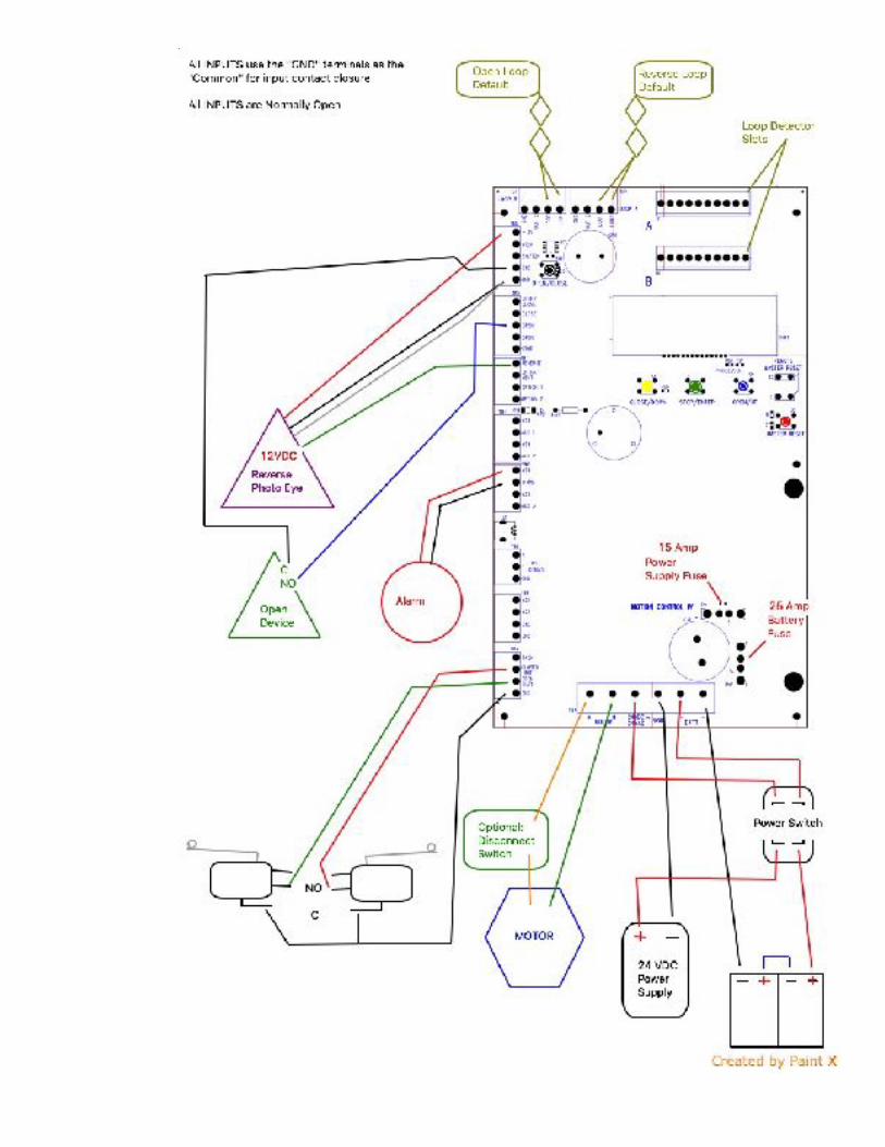
Wiring the MC4 Control Board
The MC4 control board has numerous terminals to accommodate your entire accessory wiring needs. The MC4 control board uses pull down contacts so that the ground or “GND” terminals should be used as the common contact to complete the circuit for your normally open contacts. The MC4 control board also consists of 2 separate power output supplying areas.
All of the GND terminals on the board may be used for the “ – “ power terminal or for a common contact.
The MC4 Control Board is equipped with (2) Programmable FET style outputs. These outputs can be configured to perform a variety of functions. The output terminals are labeled AUX 1 and AUX 2. The output of these terminals provide a contact to GND. A 12 or 24 VDC relay can be wired in to these outputs and either a 12v or 24v terminal for external utilization. The output relay functions and input terminal options can be programmed in the Auxiliary Settings Menu.
Loop Detector Slots and Options:
The OUT 2 and GND terminals are used when a detector (the EDI LMA-1800 or Diablo DSP-50, etc) gives the user access to the second relay of the detector. This relay might be used as an external “arming” loop contact, or other external control.
Loop A is factory defaulted to be a REVERSE from closing loop, and Loop B is factory defaulted to be an OPEN loop. Programmable Loop Modes are: Open, Reverse, Shadow, Close, Reset (anti tailgate), and Disabled
Terminals:
SW / 12v : This terminal provides +12VDC power 1/2 second before Motor activation and is maintained while in operation in both directions
The MC4 Control Board is UL325 (2018) Compliant. It has the ability to provide 4 external monitored entrapment inputs. These Inputs can be wired as follows:
Entrapment Terminal : This terminal is a programmable Monitored Entrapment device terminal. It can be programmed for either direction of travel. Products that are compatible with this terminal are those that are either 2 wire or 4 wire “Pulse” style devices. Examples of compatible devices include: EMX-inc —IRB-RET, IRB-MONMiller Edge —Prime-Guard, Reflect-Guard
Option 1 and Option 2 : These terminals are programmable for many different options (see pages 17-18). Of those options, these terminals can also be used to expand the Monitored Entrapment logic. The Option 1 and Option 2 terminals are capable of accommodating both 4 wire “pulse” style as well as “10K” monitored devices
! 12
! 13

Programming the MC4 Control Board
The following is a list of programming and available features. Please be aware that the MC4 control board is one of the most advanced gate operator circuit boards available and take care when programming and choosing desired features. Refer to this manual if a feature that you desire is needed or if any changes are necessary to be made in the menus.
The MC4 control board is divided into 7 menus. Using the Yellow, Green, and Blue programming buttons, you can scroll through the menus and select an option or enter a menu by depressing the Green Button. When changes are being made in any menus the programming “ * “ will be displayed at the top left of the screen. The 7 menus consist of the following:
Adjust the Clock Adjust Time Settings Auxiliary Settings Maintenance Menu Motor Drive Menu Digi/Tach Learning Error and Fault Log Password Protected Menu
To enter any of the menus, press the Green Button to enter the menu structure and then navigate using the Blue and Yellow Buttons. The first option that will appear is “Adjust the Clock”. At this point, you have entered the menu and may navigate to make the adjustments that you desire. To enter a menu, press the Yellow or Blue until the one you desired is displayed and push the Green to enter. To exit a sub-menu, scroll all the way until “exit the sub-menu” is displayed and then push the Green. To exit the main menu press the Yellow until the date and time is displayed.
! 14

Adjust the Clock: Adjust Date / Time
• Year = • Month = • Date = • Day = • Hour = • Minute =
Exit the sub-menu
Adjust Time Settings
• Maximum Run Timer = adjustable from 10 to 180 seconds, this timer amount represents the maximum number of seconds that the gate operator can run in one direction
• Close Delay Timer = (Timer To Close) adjustable from OFF to 4:15, this timer represents the amount of time from OFF to seconds to minutes of how long the gate waits to close from the open limit after all open and hold open and other inputs are removed
• Holiday Next ____ thru ____ (adjustable up to 8 days in advanced) This option is to be used to define what day of the week an upcoming holiday is (if it is desired that the gate not open with the 7-day open timer on that holiday) Just enter the first day of the holiday and the last day of the holiday.
• 7-day open timer = (Completely Off, Off to next {next on program}, On) this is the option in which the 7-day open timer could be activated
• P-1 Open @ 08:00am / Su Mo Tu We Th Fr Sa (These P-* options are the programmable 7 day auto open timers. You can choose the time and days that the gates automatically open and then close. There are 4 available auto open time slots. To program, adjust the desired time and then display what days you would like the timer to function. If a day is undesired, move the cursor under that day and press the programming knob to erase that day from the program. Then scroll clockwise and set the days and time for the auto close). Here is an example of the 7-day open timer:
! 15
P-1 Open: 07:00a

Adjust Time Settings (continued)
• 7Day Security Timer = (Completely Off, Off to next {next on program}, On) (The security timer has 2 available time slots that can be programmed for desired days and times to allow or secure 5 inputs. The inputs that can be secured are: Open, Exit, Open/CLose, AUX IN 1 and AUX IN 2. To program a secured input, simply program the desired time and the days to secure that input, and also when to release. Then allow the inputs by scrolling to “Secure Inputs, Allow” screen and move the cursor under a desired input. To secure that input, press the programming knob. The inputs that remain displayed will be allowed during the Secured Input timer.
• Secure Inputs, Allow = Open, Exit, Open/Close, Option 1 and Option 2
Exit the sub-menu
{Some possible and popular uses for the security timer are as follows: a “Free Entrance” loop by day and a “Safety” loop by night; the automatic disabling of the free exit loop after work hours; a controlled output from the auxiliary relays utilizing the Aux In terminals; etc.}
! 16
P-1 Secure at 5:30p
Secured inputs Open-Exit-Open/Close-Aux1-

Auxiliary Settings / Enter to View/Adjust
• Entrapment Input o Mon. Photoeye Open o Mon. Photoeye Close (default) o OFF
• Option 1 and 2 Input Terminals (These are available programmable inputs that can be programmed to take on the function that is selected when the Option 1 / Option 2 terminal is activated)
o Open o Reverse o Shadow o Fire o Close o Photo Eye Close (stops the gate from closing but doesn’t reverse the gate) o 7-day Open Timer Off (turns off the 7-day open timer until the next open
schedule) (default) o Hold Open (momentary contact will hold open gate and release it) o Open/Close Terminal Logic o Emergency Close o Option In UL325 (activating this input will cause the operator to shut down and
the alarm will sound until the system is reset or power is cycled) o Abort Open (activating this input will prevent the gate from opening) o Mon. Photoeye Open (10K or 4 Wire Pulse) o Mon. Photoeye Close (10K or 4 Wire Pulse) o Monitored Edge Both (10K edge used in both directions)
• Aux 1 Output / Aux 2 Output (These are available options for the Aux 1 and Aux 2 outputs to perform if selected)
o Pulse on Open Limit (a 2 second output activation on the open limit) o Pulse on Close Limit (a 2 second output activation on the close limit) o Hold on Open Limit (latches the output when on the open limit) o Hold on Close Limit (latches the output when on the close limit) (default) o Pulse on Opening (a 2 second output activation when gate is opening) o Pulse on Closing (a 2 second output activation when gate is closing) o Hold on Opening (latches the output when gate is opening) o Hold on Closing (latches the output when gate is closing) o Hold on UL-325 Alarm (latches the ouput upon a UL-325 alarm) o Option 1 Input Received (activates the output when the Option 1 input is in use) o Option 2 Input Received (activates the output when the Option 2 input is in use) o Low DC Power (activate the output upon low DC power detection, a value of
equal to or less than 75% of full power supplied) o Maintenance Request (activates the output upon a maintenance request) o Hold on Motor Run (activates the output whenever the gate is running) o Limit Secure Notification (activates output when the Limit Secure feature has
been enabled and the gate has been forced open off of its closed limit switch) ! 17

Auxiliary Settings / Enter to View/Adjust (continued)
o Lock Routines (activates the output to perform the desired Lock routine that has been selected —- See Lock Relay Options below)
o Open Input Received (activates the output when an OPEN Input has been received at the Open Terminal)
o Reverse Input Received (activates the output when an REVERSE Input has been received at the Reverse Terminal)
• Aux 1 Normal Output= Normally Open (default) Normally Closed
• Aux 2 Normal Output= Normally Open (default) Normally Closed
• MRT Exp Limit Option =OFF, ON (This will signal a limit switch in its last direction if the Maximum Run Timer expires)
• Open/Close Terminal Function= Open-Stop-Close (default), Open Only, Partial Open Open-Stop-Close (default) Open Only Partial Open
• Partial Open Timed Run = 05 Seconds (default) (this is the programmable amount of time that the gate can run when a partial open signal is given through the Open/Close Terminal when programmed as Partial Open)
• Lock Relay – 2 seconds, 7 seconds, Full Cycle • Loop A=
Reverse (default), Open, Close, Shadow, Reset (anti Tailgate), Disable • Loop B=
Open (default), Reverse, Close, Shadow, Reset (anti Tailgate), Disable
Exit the sub-menu
! 18

Maintenance Menu
• Main Power Fail= Normal (default) : gate continues to run Hold Open : Gate opens and holds open until AC Power is restored
• Maintenance Request in = Cycles (default) or Days
• Maintenance Request after = _ _ Cycles or _ _ Days
• Current _ _ _ _ _ _ Cycles/Days – Enter to reset (pressing the programming knob to enter will erase and reset the current maintenance count)
• Total Operator Cycle = M1 00,000,000 (this is displaying the total accumulated cycles and is non-resettable)
• Low Power Function = Hold Open (default)– the gate will hold open until battery is above 75% full Normal – the gate will continue to function regardless of low power Fire – the gate will only open from a FIRE input
• Motion Warning Type = 3 Sec Pre-Warn – Activates the alarm relay for 3 seconds before motion Motion Warning – Activates the alarm relay 3 seconds before motion as well as during gate motion Off (default)– no audible notification of gate motion
• Limit Secure = Off (default) or On
• Input Contacts = Momentary (default) or Constant (affects the OPEN and CLOSE inputs and allows that gate to operate without the monitored entrapment devices being present)
• Motor Diagnostics = Off (default) or On (see below)
• Temperature Cal Display = (allows the thermostat to be calibrated) •Exit the sub-menu
(The Motor Diagnostics option is an extraordinary feature that can allow precise adjustment of the motor maximum output force. When motor diagnostics are turned on, upon exiting the menus, the display will reflect the motor amperage high and voltage low in real time when the motor is running. At the end of the cycle, the highest amperage and lowest voltage that was last detected will be displayed. By using this feature, proper adjustment to the open and close force settings can be obtained. Be sure to turn the diagnostic features off when not required)
! 19

Motor Drive Menu • Single (default), Master, Slave
• Open Force = user selectable amperage level from 00.1 to 16.0 Default=10.0 amps
• Close Force = user selectable amperage level from 00.1 to 16.0 Default=10.0 amps
• Force Delay= 0.5 (recommended) this is the selectable time from .5 seconds up to 2 seconds in which the amperage may be reached or exceeded before the gate reverses due to a motor open or close force alarm
• Max Speed = user selectable maximum motor speed from 10% to 100%
• Min Speed = user selectable minimum motor speed from 10% to 90%
• Open Delay = sets the desired open delay from 0.0 seconds to 5.0 seconds
• Close Delay = sets the desired close delay from 0.0 seconds to 5.0 seconds
• Acceleration Step Size = sets the rate of motor acceleration- the higher the rate, the faster the ramp up to the maximum set speed
• Deceleration Step Size = sets the rate of motor deceleration- the higher the rate, the faster the ramp down to the minimum set speed
Exit the sub-menu
Digi/Tach Learning – Enter if Applicable (This is the menu that will allow you to set the location of the soft stop in a percentage value.)
Use the Blue/Yellow to drive gate to set the manual limit switches
o Close limit is _ _ _ _ counts
o Open limit is _ _ _ _ counts
o Open Slow Down at _ _% (this is the percent of gate travel that the soft stop would begin)
o Close Slow Down at _ _% (this is the percent of gate travel that the soft stop would begin)
Exit the sub-menu
! 20

Error and Fault Log – Press Enter to View
This menu will display the recent faults, errors, or important notifications as well as the time and date that they occurred and what the recorded temperature was at that time. You may scroll left or right and view the events as they occurred with the date and time displayed. To exit the sub-menu, just press the Green enter button
! 21

Quick Start Guide: Example of an SL-G5 installation
The following are instructions on how to simply and quickly program an MC4 controlled gate operator after it has been mounted to concrete pad and attached to the gate.
Be sure to disconnect any magnetic or other gate locks/brakes before setting limits on an operator.
1. With the power and battery disconnected, attach the SL-G5 motor and limit wires to the board according to the direction that the gate opens:
The following example is for Left Hand operation • The WHITE wire inserted in the MOTOR A terminal • The BLACK wire inserted in the MOTOR B terminal • Open and Closed limit switch wires are terminated accordingly with their
commons inserted in the GND terminals of the board
2. Reconnect the power and / or batteries and turn on the On/Off switch on the side of the control box
3. in the Digi/Tach menu: press the Green button, “No Digitizer Found” is displayed. Press the Green Button again and “*” is displayed at the top left corner of the display
4. Push and hold the “BLUE” manual override button on the control board to operate the gate in the open direction or press the “Yellow” button to run the gate in the close direction. When the gate reaches the desired open position, manually adjust the open limit cam until it activates the open limit switch and the OPEN LIMIT LED (DS18) is illuminated with a Green LED
5. Push and hold the “Yellow” manual override button on the control board to operate the gate in the close direction. When the gate reaches the desired closed position, manually adjust the close limit cam until it activates the close limit switch and the CLOSE LIMIT LED (DS17) is illuminated with a Red LED
6. To adjust the soft stop position navigate in the Digi/TACH menu unitl “Begin Slow Open” is displayed. To adjust the gate so that it slows down from full speed at a sooner position, lower the percentage. To slow the gate down later in its full cycle, increase the percentage.
7. Do the same for the “Begin Slow Close”
8. When finished, press the Blue Button until “Exit the sub-menu” and push the Green Button.
9. Use the Yellow Button to return to the main screen showing the Date and Time
10. If you desire to change the rate of the soft start or soft stop, you can do so by adjusting the rate of acceleration or deceleration in the “Motor Drive Menu”
! 22

Quick Start Guide: Example of an SL-G5 installation (continued)
11. It is highly recommended that you verify the motors running amperage so that you can properly adjust the maximum amperage force for each motor. To do this navigate the menu until the display reads “Maintenance Menu” and push Green button to enter to adjust. Navigate until the display reads “Motor Diagnostics – Off”. Press the Green to enter and the programming “*” will be displayed. Use the Blue or Yellow until “ON” is displayed, press the Green again so that the “*" disappears and then use the Blue until “Exit the sub-menu” and push the Green to exit.
12.From here use the Yellow until the date and time is displayed. Using the Open/Close button or any desired open contact, operate the gate and view the amperage. When the operator is not running, the previous highest amperage and lowest voltage requirements will be displayed. By using this information, you can adjust the motor amperage in the “Motor Drive Menu” accordingly.
13.Return to the “Maintenance Menu” and turn off the “Motor Diagnostics” when you no longer need them displayed, or simply press the Master Reset button.
At this point, the SL-G5 has been learned and may be operated. Remember to turn off power via the On/Off switch before and during any accessory wiring. You may also reconnect any magnetic or other gate locks.
! 23

Troubleshooting Guide
www.iqgatesystems.com 1-801-455-7961
Because of the LCD display, LED terminal identifiers, and the on-screen messages, troubleshooting the MC4 Control Board is very easy if there is ever a problem that is encountered. Some of the on-screen messages that might be displayed are as followed:
This list consists of Displayed Actions. The highlighted ones will also be logged in the Fault/Error menu.
! 24
Close Timer On
Open Detected
Open/Close Detected
7-day Timer
Shadow Detected
Reverse Loop/Term
Open Lim Secure Open Limit Secured
Aux Input Term
Open Limit
Close Limit
Close Detected
UL-325 Alarm
UL-325 Reset
Entrapment Detected
FIRE Input
Maint. Request
Close Force
Open Force
ENCODER err
Close Lim Secure Close Limit Secured
Secured Input Secured Timer input
Stop Detected
Max Run Expired
Low DC Power
AC Power Lost
Setup Change
Open Loop > 3min Active more then 3
Reverse > 3min Active more then 3
Shadow > 3min Active more then 3
Option 1 / 2 > 3min Active more then 3

Problem Possible Cause Solution
Gate Won’t OpenThe input that is being used to open gate is being secured by the security timer
Open limit tripped/active
Low Power – set on FIRE Option
Stop command active
Close command active
Abort command active
Entrapment command active
Blown Motor Fuse
Gate is in UL entrapment
No Power
Encoder Failure
Option 1 / 2 active
Check the Display and all LED’s
Check if security timer is active and what inputs are being secured.
Verify limit position / reset limit
Check battery voltage
Remove stop signal / input
Remove close signal / input
Remove abort signal / input
Check for activation/failure
Check board fuses
Survey the area surrounding the gate – when clear, activate the Reset button / terminal
Check for any indication of power supplied Operate gate and view the “blinking” output from the board TACH terminal Verify Option 1 and 2 settings and remove contact
! 25

The MC4 Control Board and SLG5 operators are low maintenance but still require regular attention to remain safe and efficient. However, every 6 months to 1 year, a qualified service technician should inspect, test, and adjust the inherent safety sensor as well as the batteries, chains, and grease the bearings. Also, all bolts and nuts should be tightened and checked for wear. Every month, all external accessories including entrapment devices should also be tested for proper operation and wiring compliance.
Gate Won’t Close
Gate Won’t Close
Low Power
7-day timer hold open
Close timer not on / active
Open loop detector active
Reverse loop detector active
Shadow loop detector active
Open input active Stop input active Reverse input active
Encoder Failure
Gate is in UL Entrapment
Blown Motor Fuse
Entrapment command active
Option 1 / 2 active
Check the Display and all LED’s
Check the Battery voltage and low power function setting Check if the 7-day timer is on and if the program time is active Check the close timer setting
Check for a vehicle present, reset loop detector or remove input, check the loop integrity Check for a vehicle present, reset loop detector or remove input, check the loop integrity Check for a vehicle present, reset loop detector or remove input, check the loop integrity Remove contact from input Remove contact from input Remove contact from input
Operate gate and view the “blinking” output from the TACH terminal Survey the area surrounding the gate – when clear, activate the UL-Reset button / terminal
Check board fuses
Check for activation/failure
Verify Option 1 and 2 setting and remove contact
Gate reverses when closingCheck all of the above causes
Check the display for Close Force or Encoder alert
Check the Display and all LED’s
Check all of the above solutions
Verify close force setting and adjust if necessary
! 26

Page left blank intentionally
! 27

! 28