ip routing protocols commands - cisco网络技 - … ip routing protocols commands v-211 example the...
TRANSCRIPT

IP Routing Protocols Commands V-209
IP Routing Protocols Commands
Cisco’s implementation of the Internet Protocol (IP) suite provides all major services contained inthe Transmission Control Protocol (TCP)/IP specifications.
Use the commands in this chapter to configure and monitor the IP routing protocols. For IP routingprotocol configuration information and examples, refer to the “Configuring IP Routing Protocols”chapter of theNetwork Protocols Configuration Guide, Part 1.

V-210 Network Protocols Command Reference, Part 1
accept-lifetime
accept-lifetimeTo set the time period during which the authentication key on a key chain is received as valid, usethe accept-lifetimekey chain key configuration command. To revert to the default value, use thenoform of this command.
accept-lifetimestart-time{ infinite | end-time | duration seconds}no accept-lifetime [start-time{ infinite | end-time | duration seconds}]
Syntax Description
DefaultForever (Starting time is January 1, 1993, and ending time is infinite.)
Command ModeKey chain key configuration
Usage GuidelinesThis command first appeared in Cisco IOS Release 11.1.
Only RIP Version 2 uses key chains.
Specify astart-time and one of the following:infinite , end-time, orduration seconds.
We recommend running NTP or some other time synchronization method if you assign a lifetime toa key.
start-time Beginning time that the key specified by thekey command is valid to bereceived. The syntax can be either of the following:
hh:mm:ss Month date year
hh:mm:ss date Month year
hh—hours
mm—minutes
ss—seconds
date—date (1-31)
Month—first three letters of the month
year—year (four digits)
The default start time and the earliest acceptable date is January 1, 1993.
infinite Key is valid to be received from thestart-time on.
end-time Key is valid to be received from thestart-time until end-time. Theend-timemust be after thestart-time. The syntax is the same as that forstart-time.The default end time is an infinite time period.
duration seconds Length of time (in seconds) that the key is valid to be received.

accept-lifetime
IP Routing Protocols Commands V-211
ExampleThe following example configures a key chain calledtrees. In this example, the software will alwaysaccept and send willow as a valid key. The key chestnut will be accepted from 1:30 p.m. to 3:30 p.m.and be sent from 2:00 p.m. to 3:00 p.m. The overlap allows for migration of keys or discrepanciesin the router's set time. Likewise, the key birch immediately follows chestnut, and there is a halfhourleeway on each side to handle time-of-day differences.
interface ethernet 0 ip rip authentication key-chain trees ip rip authentication mode md5!router rip network 172.19.0.0 version 2!key chain trees key 1 key-string willow key 2 key-string chestnut accept-lifetime 13:30:00 Jan 25 1996 duration 7200 send-lifetime 14:00:00 Jan 25 1996 duration 3600 key 3 key-string birch accept-lifetime 14:30:00 Jan 25 1996 duration 7200 send-lifetime 15:00:00 Jan 25 1996 duration 3600
Related Commandskeykey chainkey-stringsend-lifetimeshow key chain

V-212 Network Protocols Command Reference, Part 1
aggregate-address
aggregate-addressTo create an aggregate entry in a BGP routing table, use theaggregate-addressrouter configurationcommand. To disable this feature, use theno form of this command.
aggregate-addressaddress mask[as-set] [summary-only] [suppress-mapmap-name][advertise-mapmap-name] [attribute-map map-name]
no aggregate-addressaddress mask[as-set] [summary-only] [suppress-mapmap-name][advertise-mapmap-name] [attribute-map map-name]
Syntax Description
DefaultDisabled
Command ModeRouter configuration
Usage GuidelinesThis command first appeared in Cisco IOS Release 10.0.
You can implement aggregate routing in BGP either by redistributing an aggregate route into BGPor by using this conditional aggregate routing feature.
Using theaggregate-addresscommand with no arguments will create an aggregate entry in the BGProuting table if there are any more-specific BGP routes available that fall in the specified range. Theaggregate route will be advertised as coming from your autonomous system and has the atomicaggregate attribute set to show that information might be missing. (By default, the atomic aggregateattribute is set unless you specify theas-set keyword.)
Using theas-setkeyword creates an aggregate entry using the same rules that the command followswithout this keyword, but the path advertised for this route will be an AS_SET consisting of allelements contained in all paths that are being summarized. Do not use this form of
address Aggregate address.
mask Aggregate mask.
as-set (Optional) Generates autonomous system set path information.
summary-only (Optional) Filters all more specific routes from updates.
suppress-mapmap-name (Optional) Name of route map used to select the routes to besuppressed.
advertise-mapmap-name (Optional) Name of route map used to select the routes to createAS-SET origin communities.
attribute-map map-name (Optional) Name of route map used to set the attribute of theaggregate route.

aggregate-address
IP Routing Protocols Commands V-213
aggregate-addresswhen aggregating many paths, because this route must be continually withdrawnand re-updated as autonomous system path reachability information for the summarized routeschanges.
Using thesummary-only keyword not only creates the aggregate route (for example, 193.*.*.*) butwill also suppress advertisements of more-specific routes to all neighbors. If you only want tosuppress advertisements to certain neighbors, you may use the neighbor distribute-list command,with caution. If a more specific route leaks out, all BGP speakers will prefer that route over theless-specific aggregate you are generating (using longest-match routing).
Using the suppress-mapkeyword creates the aggregate route but suppresses advertisement ofspecified routes. You can use thematch clauses of route maps to selectively suppress some morespecific routes of the aggregate and leave others unsuppressed. IP access lists and autonomoussystem path access lists match clauses are supported.
ExampleIn the following example, an aggregate address is created. The path advertised for this route will bean AS_SET consisting of all elements contained in all paths that are being summarized.
router bgp 5aggregate-address 193.0.0.0 255.0.0.0 as-set
Related Commandsmatch as-pathmatch ip addressroute-map

V-214 Network Protocols Command Reference, Part 1
area authentication
area authenticationTo enable authentication for an OSPF area, use the area authentication router configurationcommand. To remove an area’s authentication specification or a specified area from theconfiguration, use theno form of this command.
areaarea-id authentication [message-digest]no areaarea-id authenticationno area area-id
Syntax Description
DefaultType 0 authentication (no authentication)
Command ModeRouter configuration
Usage GuidelinesThis command first appeared in Cisco IOS Release 10.0. Themessage-digest keyword firstappeared in Cisco IOS Release 11.0.
Specifying authentication for an area sets the authentication to Type 1 (simple password) as specifiedin RFC 1247. If this command is not included in the configuration file, authentication of Type 0 (noauthentication) is assumed.
The authentication type must be the same for all routers and access servers in an area. Theauthentication password for all OSPF routers on a network must be the same if they are tocommunicate with each other via OSPF. Use theip ospf authentication-keycommand to specifythis password.
If you enable MD5 authentication with themessage-digest keyword, you must configure a passwordwith theip ospf message-digest-key command.
To remove the area’s authentication specification, use theno form of this command with theauthentication keyword. To remove the specified area from the software configuration, use thecommandno area area-id (with no other keywords).
ExampleThe following example mandates authentication for areas 0 and 36.0.0.0 of OSPF routingprocess 201. Authentication keys are also provided.
interface ethernet 0ip address 131.119.251.201 255.255.255.0ip ospf authentication-key adcdefgh!interface ethernet 1
area-id Identifier of the area for which authentication is to be enabled. Theidentifier can be specified as either a decimal value or an IP address.
message-digest (Optional) Enables MD5 authentication on the area specified byarea-id.

area authentication
IP Routing Protocols Commands V-215
ip address 36.56.0.201 255.255.0.0ip ospf authentication-key ijklmnop!router ospf 201network 36.0.0.0 0.255.255.255 area 36.0.0.0network 131.119.0.0 0.0.255.255 area 0area 36.0.0.0 authenticationarea 0 authentication
Related Commandsarea default-costarea stubip ospf authentication-keyip ospf message-digest-key

V-216 Network Protocols Command Reference, Part 1
area default-cost
area default-costTo specify a cost for the default summary route sent into a stub area, use the area default-costrouterconfiguration command. To remove the assigned default route cost, use theno form of thiscommand.
areaarea-iddefault-costcostno areaarea-iddefault-costcost
Syntax Description
DefaultCost of 1
Command ModeRouter configuration
Usage GuidelinesThis command first appeared in Cisco IOS Release 10.0.
The command is used only on an area border router attached to a stub area.
There are two stub area router configuration commands: thestub anddefault-cost options of thearea command. In all routers and access servers attached to the stub area, the area should beconfigured as a stub area using thestub option of thearea command. Use thedefault-cost optiononly on an area border router attached to the stub area. The default-cost option provides the metricfor the summary default route generated by the area border router into the stub area.
ExampleThe following example assigns a default-cost of 20 to stub network 36.0.0.0:
interface ethernet 0ip address 36.56.0.201 255.255.0.0!router ospf 201network 36.0.0.0 0.255.255.255 area 36.0.0.0area 36.0.0.0 stubarea 36.0.0.0 default-cost 20
Related Commandsarea authenticationarea stub
area-id Identifier for the stub area. The identifier can be specified aseither a decimal value or as an IP address.
cost Cost for the default summary route used for a stub area. Theacceptable value is a 24-bit number.

area nssa
IP Routing Protocols Commands V-217
area nssaTo configure an area as a not so stubby area (NSSA),use the area nssarouter configurationcommand. To remove the nssa distinction from the area, use theno form of this command.
area area-id nssa[no-redistribution ] [default-information-originate]no areaarea-id nssa
Syntax Description
DefaultNo NSSA area is defined.
Command ModeRouter configuration
Usage GuidelinesThis command first appeared in Cisco IOS Release 10.0.
ExampleIn the following example, NSSA authentication is enabled on area 1:
router ospf1redistribute rip subnetsnetwork 172.19.92.0.0.0.0.255 area 1area 1 nssa
area-id Identifier of the area for which authentication is to be enabled. Theidentifier can be specified as either a decimal value or an IP address.
no-redistribution (Optional) Used when the router is a NSSA ABR and you want theredistribute command to import routes only into the normal areas, butnot into the NSSA area.
default-information-originate
(Optional) Used to generate a Type 7 default into the NSSA area. Thisargument only takes effect on NSSA ABR.

V-218 Network Protocols Command Reference, Part 1
area-password
area-passwordTo configure the IS-IS area authentication password, use thearea-password router configurationcommand. To disable the password, use theno form of this command.
area-passwordpasswordno area-password[password]
Syntax Description
DefaultNo area password is defined.
Command ModeRouter configuration
Usage GuidelinesThis command first appeared in Cisco IOS Release 10.0.
This password is inserted in Level 1 (station router level) link state PDUs (LSPs), complete sequencenumber PDUs (CSNPs), and partial sequence number PDUs (PSNP).
ExampleThe following example assigns an area authentication password:
router isisarea-password angel
Related Commanddomain-password
password Password you assign.

area range
IP Routing Protocols Commands V-219
area rangeTo consolidate and summarize routes at an area boundary, use the area range router configurationcommand. To disable this function, use theno form of this command.
areaarea-id rangeaddress maskno areaarea-id rangeaddress mask
Syntax Description
DefaultDisabled
Command ModeRouter configuration
Usage GuidelinesThis command first appeared in Cisco IOS Release 10.0.
Thearea range command is used only with area border routers (ABRs). It is used to consolidate orsummarize routes for an area. The result is that a single summary route is advertised to other areasby the ABR. Routing information is condensed at area boundaries. External to the area, a single routeis advertised for each address range. This is calledroute summarization.
Multiple area router configuration commands specifying therange option can be configured. Thus,OSPF can summarize addresses for many different sets of address ranges.
ExampleThe following example specifies one summary route to be advertised by the ABR to other areas forall subnets on network 36.0.0.0 and for all hosts on network 192.42.110.0:
interface ethernet 0ip address 192.42.110.201 255.255.255.0!interface ethernet 1ip address 36.56.0.201 255.255.0.0!router ospf 201network 36.0.0.0 0.255.255.255 area 36.0.0.0network 192.42.110.0 0.0.0.255 area 0area 36.0.0.0 range 36.0.0.0 255.0.0.0area 0 range 192.42.110.0 255.255.255.0
area-id Identifier of the area about which routes are to be summarized.It can be specified as either a decimal value or as an IP address.
address IP address.
mask IP mask.

V-220 Network Protocols Command Reference, Part 1
area stub
area stubTo define an area as a stub area, use the area stub router configuration command. To disable thisfunction, use theno form of this command.
areaarea-id stub [no-summary]no areaarea-id stub
Syntax Description
DefaultNo stub area is defined.
Command ModeRouter configuration
Usage GuidelinesThis command first appeared in Cisco IOS Release 10.0.
You must configure thearea stub command on all routers and access servers in the stub area. Usethearea router configuration command with thedefault-cost option to specify the cost of a defaultinternal router sent into a stub area by an area border router.
There are two stub area router configuration commands: thestub anddefault-cost options of thearea router configuration command. In all routers attached to the stub area, the area should beconfigured as a stub area using thestub option of thearea command. Use thedefault-cost optiononly on an ABR attached to the stub area. The default-cost option provides the metric for thesummary default route generated by the area border router into the stub area.
To further reduce the number of link state advertisements (LSA) sent into a stub area, you canconfigureno-summary on the ABR to prevent it from sending summary LSAs (LSA type 3) intothe stub area.
ExampleThe following example assigns a default cost of 20 to stub network 36.0.0.0:
interface ethernet 0ip address 36.56.0.201 255.255.0.0!router ospf 201network 36.0.0.0 0.255.255.255 area 36.0.0.0area 36.0.0.0 stubarea 36.0.0.0 default-cost 20
area-id Identifier for the stub area. The identifier can be either a decimal value oran IP address.
no-summary (Optional) Prevents an ABR from sending summary link advertisementsinto the stub area.

area stub
IP Routing Protocols Commands V-221
Related Commandsarea authenticationarea default-cost

V-222 Network Protocols Command Reference, Part 1
area virtual-link
area virtual-linkTo define an OSPF virtual link, use the area virtual-link router configuration command with theoptional parameters. To remove a virtual link, use theno form of this command.
areaarea-id virtual-link router-id [hello-interval seconds] [retransmit-interval seconds][transmit-delay seconds] [dead-interval seconds] [[authentication-keykey] |[message-digest-keykeyid md5 key]]
no areaarea-id virtual-link router-id [hello-interval seconds] [retransmit-interval seconds][transmit-delay seconds] [dead-interval seconds] [[authentication-keykey] |[message-digest-keykeyid md5 key]]
Syntax Description
area-id Area ID assigned to the transit area for the virtual link. This canbe either a decimal value or a valid IP address. There is nodefault.
router-id Router ID associated with the virtual link neighbor. The routerID appears in theshow ip ospf display. It is internally derivedby each router from the router’s interface IP addresses. Thisvalue must be entered in the format of an IP address. There is nodefault.
hello-interval seconds (Optional) Time in seconds between the hello packets that theCisco IOS software sends on an interface. Unsigned integervalue to be advertised in the software’s hello packets. The valuemust be the same for all routers and access servers attached to acommon network. The default is 10 seconds.
retransmit-interval seconds (Optional) Time in seconds between link state advertisementretransmissions for adjacencies belonging to the interface.Expected round-trip delay between any two routers on theattached network. The value must be greater than the expectedround-trip delay. The default is 5 seconds.
transmit-delay seconds (Optional) Estimated time in seconds it takes to transmit a linkstate update packet on the interface. Integer value that must begreater than zero. Link state advertisements in the update packethave their age incremented by this amount before transmission.The default value is 1 second.
dead-interval seconds (Optional) Time in seconds that a software’s hello packets arenot seen before its neighbors declare the router down. Unsignedinteger value. The default is four times the hello interval, or40 seconds. As with the hello interval, this value must be thesame for all routers and access servers attached to a commonnetwork.

area virtual-link
IP Routing Protocols Commands V-223
Defaultsarea-id: No area ID is predefined.router-id: No router ID is predefined.hello-interval seconds: 10 secondsretransmit-interval seconds: 5 secondstransmit-delay seconds: 1 seconddead-interval seconds: 40 secondsauthentication-keykey: No key is predefined.message-digest-keykeyidmd5 key: No key is predefined.
Command ModeRouter configuration
Usage GuidelinesThis command first appeared in Cisco IOS Release 10.0. The following keywords and argumentsfirst appeared in Cisco IOS Release 11.0:message-digest-keykeyidmd5 key.
In OSPF, all areas must be connected to a backbone area. If the connection to the backbone is lost,it can be repaired by establishing a virtual link.
The smaller the hello interval, the faster topological changes will be detected, but more routingtraffic will ensue.
The setting of the retransmit interval should be conservative, or needless retransmissions will result.The value should be larger for serial lines and virtual links.
The transmit delay value should take into account the transmission and propagation delays for theinterface.
The Cisco IOS software will use the specified authentication key only when authentication isenabled for the backbone with thearea area-id authentication router configuration command.
authentication-keykey (Optional) Password to be used by neighboring routers. Anycontinuous string of characters that you can enter from thekeyboard up to 8 bytes long. This string acts as a key that willallow the authentication procedure to generate or verify theauthentication field in the OSPF header. This key is inserteddirectly into the OSPF header when originating routing protocolpackets. A separate password can be assigned to each networkon a per-interface basis. All neighboring routers on the samenetwork must have the same password to be able to route OSPFtraffic. The password is encrypted in the configuration file if theservice password-encryption command is enabled. There is nodefault value.
message-digest-keykeyidmd5key
(Optional) Key identifier and password to be used byneighboring routers and this router for MD5 authentication. Thekeyid is a number in the range 1 to 255. Thekey is analphanumeric string of up to 16 characters. All neighboringrouters on the same network must have the same key identifierand key to be able to route OSPF traffic. There is no defaultvalue.

V-224 Network Protocols Command Reference, Part 1
area virtual-link
The two authentication schemes, simple text and MD5 authentication, are mutually exclusive. Youcan specify one or the other or neither. Any keywords and arguments you specify afterauthentication-keykeyor message-digest-keykeyidmd5 key are ignored. Therefore, specify anyoptional arguments before such a keyword-argument combination.
Note Each virtual link neighbor must include the transit area ID and the corresponding virtual linkneighbor’s router ID in order for a virtual link to be properly configured. Use theshow ip ospfEXECcommand to see the router ID.
ExamplesThe following example establishes a virtual link with default values for all optional parameters:
router ospf 201network 36.0.0.0 0.255.255.255 area 36.0.0.0area 36.0.0.0 virtual-link 36.3.4.5
The following example establishes a virtual link with MD5 authentication:
router ospf 201network 36.0.0.0 0.255.255.255 area 36.0.0.0area 36.0.0.0 virtual-link 36.3.4.5 message-digest-key 3 md5 sa5721bk47
Related CommandsA dagger (†) indicates that the command is documented outside this chapter.
area authenticationservice password-encryption†
show ip ospf

autonomous-system (EGP)
IP Routing Protocols Commands V-225
autonomous-system (EGP)To specify the local autonomous system that the Cisco IOS software resides in for EGP, use theautonomous-system global configuration command. To remove the autonomous systemnumber, use theno form of this command.
autonomous-systemlocal-asno autonomous-systemlocal-as
Syntax Description
DefaultNo local autonomous system is specified.
Command ModeGlobal configuration
Usage GuidelinesThis command first appeared in Cisco IOS Release 10.0.
Before you can set up EGP routing, you must specify an autonomous system number. The localautonomous system number will be included in EGP messages sent by the software.
ExampleThe following sample configuration specifies an autonomous system number of 110:
autonomous-system 110
Related Commandrouter egp
local-as Local autonomous system number to which the router belongs.

V-226 Network Protocols Command Reference, Part 1
auto-summary
auto-summaryTo restore the default behavior of automatic summarization of subnet routes into network-levelroutes, use theauto-summary router configuration command. To disable this feature and transmitsubprefix routing information across classful network boundaries, use theno form of this command.
auto-summaryno auto-summary
Syntax DescriptionThis command has no arguments or keywords.
DefaultEnabled (the software summarizes subprefixes to the classful network boundary when crossingclassful network boundaries).
Command ModeRouter configuration
Usage GuidelinesThis command first appeared in Cisco IOS Release 10.0.
Route summarization reduces the amount of routing information in the routing tables.
By default, BGP does not accept subnets redistributed from IGP. To advertise and carry subnet routesin BGP, use an explicitnetwork command or theno auto-summary command. If you disableauto-summarization and have not entered anetwork command, you will not advertise networkroutes for networks with subnet routes unless they contain a summary route.
IP Enhanced IGRP summary routes are given an administrative distance value of 5. You cannotconfigure this value.
RIP Version 1 always uses automatic summarization. If you are using RIP Version 2, you can turnoff automatic summarization by specifyingno auto-summary. Disable automatic summarization ifyou must perform routing between disconnected subnets. When automatic summarization is off,subnets are advertised.
ExamplesIn the following example, network numbers are not summarized automatically:
router bgp 6no auto-summary
The following example disables automatic summarization for process eigrp 109:
router eigrp 109no auto-summary
Related Commandip summary-address eigrp

bgp always-compare-med
IP Routing Protocols Commands V-227
bgp always-compare-medTo allow the comparison of the Multi Exit Discriminator (MED) for paths from neighbors indifferent autonomous systems, use the bgp always-compare-medrouter configuration command.To disallow the comparison, use theno form of this command.
bgp always-compare-medno bgp always-compare-med
Syntax DescriptionThis command has no arguments or keywords.
DefaultThe Cisco IOS software does not compare MEDs for paths from neighbors in different autonomoussystems.
Command ModeRouter configuration
Usage GuidelinesThis command first appeared in Cisco IOS Release 11.0.
The MED is one of the parameters that is considered when selecting the best path among manyalternative paths. The path with a lower MED is preferred over a path with a higher MED.
By default, during the best-path selection process, MED comparison is done only among paths fromthe same autonomous system. This command changes the default behavior by allowing comparisonof MEDs among paths regardless of the autonomous system from which the paths are received.
ExampleIn the following example, the BGP speaker in autonomous system 100 is configured to compareMEDs among alternative paths, regardless of the autonomous system from which the paths arereceived:
router bgp 109bgp always-compare-med

V-228 Network Protocols Command Reference, Part 1
bgp client-to-client reflection
bgp client-to-client reflectionTo restore route reflection from a BGP route reflector to clients, use thebgp client-to-clientreflection router configuration command. To disable client-to-client reflection, use theno form ofthis command.
bgp client-to-client reflectionno bgp client-to-client reflection
Syntax DescriptionThis command has no arguments or keywords.
DefaultWhen a route reflector is configured, the route reflector reflects routes from a client to other clients.
Command ModeRouter configuration
Usage GuidelinesThis command first appeared in Cisco IOS Release 11.1.
By default, the clients of a route reflector are not required to be fully meshed and the routes from aclient are reflected to other clients. However, if the clients are fully meshed, route reflection is notrequired. Use theno bgp client-to-client reflectioncommand to disable client-to-client reflection.
If client-to-client reflection is enabled, the clients of a route reflector cannot be members of a peergroup.
ExampleIn the following example, the local router is a route reflector. The three neighbors are fully meshed,so client-to-client reflection is disabled.
router bgp 5neighbor 155.24.95.22 route-reflector-clientneighbor 155.24.95.23 route-reflector-clientneighbor 155.24.95.24 route-reflector-clientno bgp client-to-client reflection
Related Commandsbgp cluster-idneighbor route-reflector-clientshow ip bgp

bgp cluster-id
IP Routing Protocols Commands V-229
bgp cluster-idTo configure the cluster ID if the BGP cluster has more than one route reflector, use thebgp cluster-id router configuration command. To remove the cluster ID, use theno form of thiscommand.
bgp cluster-id cluster-idno bgp cluster-idcluster-id
Syntax Description
DefaultThe router ID of the single route reflector in a cluster
Command ModeRouter configuration
Usage GuidelinesThis command first appeared in Cisco IOS Release 11.0.
Together, a route reflector and its clients form acluster.
Usually a cluster of clients will have a single route reflector. In that case, the cluster is identified bythe router ID of the route reflector. In order to increase redundancy and avoid a single point of failure,a cluster might have more than one route reflector. In this case, all route reflectors in the cluster mustbe configured with the 4-byte cluster ID so that a route reflector can recognize updates from routereflectors in the same cluster.
If the cluster has more than one route reflector, use this command to configure the cluster ID.
ExampleIn the following example, the local router is one of the route reflectors serving the cluster. It isconfigured with the cluster ID to identify the cluster.
router bgp 5neighbor 198.92.70.24 route-reflector-clientbgp cluster-id 50000
Related Commandsbgp client-to-client reflectionneighbor route-reflector-clientshow ip bgp
cluster-id Cluster ID of this router acting as a route reflector; maximum of4 bytes.

V-230 Network Protocols Command Reference, Part 1
bgp confederation identifier
bgp confederation identifierTo specify a BGP confederation identifier, use thebgp confederation identifierrouter configurationcommand. To remove the confederation identifier, use theno form of this command.
bgp confederation identifierautonomous-systemno bgp confederation identifierautonomous-system
Syntax Description
DefaultNo confederation identifier is configured.
Command ModeRouter configuration
Usage GuidelinesThis command first appeared in Cisco IOS Release 10.3.
Another way to reduce the IBGP mesh is to divide an autonomous system into multiple autonomoussystems and group them into a single confederation. Each autonomous system is fully meshed withinitself, and has a few connections to another autonomous system in the same confederation. Eventhough the peers in different autonomous systems have EBGP sessions, they exchange routinginformation as if they are IBGP peers. Specifically, the next-hop and local preference information ispreserved. This enables to you to retain a single Interior Gateway Protocol (IGP) for all theautonomous systems. To the outside world, the confederation looks like a single autonomous system.
ExampleIn the following example, the autonomous system is divided into autonomous systems 4001, 4002,4003, 4004, 4005, 4006, and 4007 and identified by the confederation identifier 5. Neighbor 1.2.3.4is someone inside your routing domain confederation. Neighbor 3.4.5.6 is someone outside yourrouting domain confederation. To the outside world, there appears to be a single autonomous systemwith the number 5.
router bgp 4001bgp confederation identifier 5bgp confederation peers 4002 4003 4004 4005 4006 4007neighbor 1.2.3.4 remote-as 4002neighbor 3.4.5.6 remote-as 510
Related Commandbgp confederation peers
autonomous-system Autonomous system number that internally includes multipleautonomous systems.

bgp confederation peers
IP Routing Protocols Commands V-231
bgp confederation peersTo configure the autonomous systems that belong to the confederation, use thebgp confederation peersrouter configuration command. To remove an autonomous system fromthe confederation, use theno form of this command.
bgp confederation peersautonomous-system[autonomous-system]no bgp confederation peersautonomous-system [autonomous-system]
Syntax Description
DefaultNo confederation peers are configured.
Command ModeRouter configuration
Usage GuidelinesThis command first appeared in Cisco IOS Release 10.3.
The autonomous systems specified in this command are visible internally to a confederation. Eachautonomous system is fully meshed within itself. Thebgp confederation identifier commandspecifies the confederation to which the autonomous systems belong.
ExampleThe following example specifies that autonomous systems 1090, 1091, 1092, and 1093 belong to asingle confederation:
router bgp 1090bgp confederation peers 1091 1092 1093
Related Commandbgp confederation identifier
autonomous-system Autonomous system number.

V-232 Network Protocols Command Reference, Part 1
bgp default local-preference
bgp default local-preferenceTo change the default local preference value, use thebgp default local-preferencerouterconfiguration command. To return to the default setting, use theno form of this command.
bgp default local-preferencevalueno bgp default local-preferencevalue
Syntax Description
DefaultLocal preference value of 100
Command ModeRouter configuration
Usage GuidelinesThis command first appeared in Cisco IOS Release 10.0.
Generally, the default value of 100 allows you to easily define a particular path as less preferablethan paths with no local preference attribute. The preference is sent to all routers and access serversin the local autonomous system.
ExampleIn the following example, the default local preference value is raised from the default of 100 to 200:
router bgp 200bgp default local-preference 200
Related Commandset local-preference
value Local preference value. Higher is more preferred. Integer from0 to 4294967295.
bgp fast-external-fallover
IP Routing Protocols Commands V-233
bgp fast-external-falloverTo immediately reset the BGP sessions of any directly adjacent external peers if the link used toreach them goes down, use the bgp fast-external-fallover router configuration command. Todisable this feature, use theno form of this command.
bgp fast-external-falloverno bgp fast-external-fallover
Syntax DescriptionThis command has no arguments or keywords.
DefaultEnabled
Command ModeRouter configuration
Usage GuidelinesThis command first appeared in Cisco IOS Release 10.0.
ExampleIn the following example, the automatic resetting of BGP sessions is disabled:
router bgp 109no bgp fast-external-fallover

V-234 Network Protocols Command Reference, Part 1
clear arp-cache
clear arp-cacheTo remove all dynamic entries from the ARP cache and to clear the fast-switching cache, use theclear arp-cacheEXEC command.
clear arp-cache
Syntax DescriptionThis command has no arguments or keywords.
Command ModeEXEC
Usage GuidelinesThis command first appeared in CiscoIOS Release 10.0.
ExampleThe following example removes all dynamic entries from the ARP cache and clears thefast-switching cache:
clear arp-cache

clear ip bgp
IP Routing Protocols Commands V-235
clear ip bgpTo reset a BGP connection using BGP soft reconfiguration, use theclear ip bgp EXEC command atthe system prompt.
clear ip bgp { * | address | peer-group name} [ soft [in | out]]
Syntax Description
Command ModeEXEC
Usage GuidelinesThis command first appeared in Cisco IOS Release 10.0.
If you specify BGP soft reconfiguration, by including thesoft keyword, the sessions are not resetand the router sends all routing updates again. To generate new inbound updates without resettingthe BGP session, the local BGP speaker should store all received updates without modificationregardless of whether it is accepted by the inbound policy. This process is memory intensive andshould be avoided if possible. Outbound BGP soft configuration does not have any memoryoverhead. You can trigger an outbound reconfiguration on the other side of the BGP session to makethe new inbound policy take effect.
Use this command whenever any of the following changes occur:
• Additions or changes to the BGP-related access lists
• Changes to BGP-related weights
• Changes to BGP-related distribution lists
• Changes in the BGP timer’s specifications
• Changes to the BGP administrative distance
• Changes to BGP-related route maps
ExampleThe following example resets all current BGP sessions:
clear ip bgp *
* Resets all current BGP sessions.
address Resets only the identified BGP neighbor.
peer-group-name Resets the specified BGP peer group.
soft (Optional) Soft reconfiguration.
in | out (Optional) Triggers inbound or outbound softreconfiguration. If thein orout option is not specified, bothinbound and outbound soft reconfiguration are triggered.

V-236 Network Protocols Command Reference, Part 1
clear ip bgp
Related Commandsshow ip bgptimers bgp

clear ip bgp peer-group
IP Routing Protocols Commands V-237
clear ip bgp peer-groupTo remove all the members of a BGP peer group, use theclear ip bgp peer-group EXEC command.
clear ip bgp peer-grouptag
Syntax Description
Command ModeEXEC
Usage GuidelinesThis command first appeared in Cisco IOS Release 11.0.
ExampleThe following example removes all members from the BGP peer groupinternal:
clear ip bgp peer-group internal
Related Commandneighbor peer-group (assigning members)
tag Name of the BGP peer group to clear.

V-238 Network Protocols Command Reference, Part 1
clear ip cgmp
clear ip cgmpTo send a CGMP leave message with a group address of 0000.0000.0000 and a unicast address of0000.0000.0000, use theclear ip cgmpEXEC command.
clear ip cgmp interface
Syntax Description
DefaultLeave message is sent on all CGMP-enabled interfaces.
Command ModeEXEC
Usage GuidelinesThis command first appeared in Cisco IOS Release 11.2.
The command instructs switches to clear all the groups they have cached.
interface Leave message is sent only on specified interface.

clear ip dvmrp routei
IP Routing Protocols Commands V-239
clear ip dvmrp routeiTo delete routes from the DVMRP routing table, use theclear ip dvmrp route EXEC command.
clear ip dvmrp route { * | route}
Syntax Description
Command ModeEXEC
Usage GuidelinesThis command first appeared in Cisco IOS Release 11.0.
ExamplesThe following example deletes route 10.1.1.1 from the DVMRP routing table:
clear ip dvmrp route 10.1.1.1
The following example deletes network 10.0.0.0 from the DVMRP routing table:
clear ip dvmrp route 10.0.0.0
* Clears all routes from the DVMRP table.
route Clears the longest matched route. Can be an IP address, anetwork number, or an IP DNS name.

V-240 Network Protocols Command Reference, Part 1
clear ip eigrp neighbors
clear ip eigrp neighborsTo delete entries from the neighbor table, use theclear ip eigrp neighborsEXEC command.
clear ip eigrp neighbors [ip-address| type number]
Syntax Description
Command ModeEXEC
Usage GuidelinesThis command first appeared in Cisco IOS Release 10.0.
ExampleThe following example removes the neighbor whose address is 160.20.8.3:
clear ip eigrp neighbors 160.20.8.3
Related Commandshow ip eigrp interfaces
ip-address (Optional) Address of the neighbor.
type number (Optional) Interface type and number. Specifying thesearguments removes from the neighbor table all entries learnedvia this interface.

clear ip igmp group
IP Routing Protocols Commands V-241
clear ip igmp groupTo delete entries from the IGMP cache, use theclear ip igmp group EXEC command.
clear ip igmp group [group-name | group-address | type number]
Syntax Description
Command ModeEXEC
Usage GuidelinesThis command first appeared in Cisco IOS Release 10.0.
The IGMP cache contains a list of the multicast groups of which hosts on the directly connectedLAN are members. If the router has joined a group, it is also listed in the cache.
To delete all entries from the IGMP cache, specify theclear ip igmp group command with noarguments.
ExampleThe following example clears entries for the multicast group 224.0.255.1 from the IGMP cache:
clear ip igmp group 224.0.255.1
Related CommandsA dagger (†) indicates that the command is documented outside this chapter.
ip host †
show ip igmp groupsshow ip igmp interface
group-name (Optional) Name of the multicast group, as defined in the DNShosts table or with theip host command.
group-address (Optional) Address of the multicast group. This is a multicast IPaddress in four-part, dotted notation.
type number (Optional) Interface type and number.

V-242 Network Protocols Command Reference, Part 1
clear ip mroute
clear ip mrouteTo delete entries from the IP multicast routing table, use theclear ip mroute EXEC command.
clear ip mroute { * | group [source]}
Syntax Description
Command ModeEXEC
Usage GuidelinesThis command first appeared in Cisco IOS Release 10.0.
ExamplesThe following example deletes all entries from the IP multicast routing table:
clear ip mroute *
The following example deletes from the IP multicast routing table all sources on the 10.3.0.0 subnetthat are transmitting to the multicast group 224.2.205.42. Note that this example deletes all sourceson network 10.3, not individual sources.
clear ip mroute 224.2.205.42 10.3.0.0
Related CommandsA dagger (†) indicates that the command is documented outside this chapter.
ip host †
show ip mroute
* Deletes all entries from the IP multicast routing table.
group Can be either one of the following:
• Name of the multicast group, as defined in the DNS hosts table or withthe ip host command.
• IP address of the multicast group. This is a multicast IP address infour-part, dotted notation.
source (Optional) If you specify a group name or address, you can also specify aname or address of a multicast source that is transmitting to the group. Asource does not need to be a member of the group.
clear ip mroute group
IP Routing Protocols Commands V-243
clear ip mroute groupTo delete entries from IGMP cache, use theclear ip mroute group EXEC command.
clear ip mroute { * | group [source]}
Syntax Description
Command ModeEXEC
Usage GuidelinesThis command first appeared in Cisco IOS Release 11.2.
ExampleThe following example deletes all entries from the IP multicast routing table:
clear ip mroute group*
Related CommandsA dagger (†) indicates that the command is documented outside this chapter.
ip host †
show ip mroute
* Deletes all entries from the IP multicast routing table.
group Can be either one of the following:
• Name of the multicast group, as defined in the DNS hosts table or withthe ip host command.
• IP address of the multicast group. This is a multicast IP address infour-part, dotted notation.
source (Optional) If you specify a group name or address, you can also specify aname or address of a multicast source that is transmitting to the group. Asource does not need to be a member of the group.

V-244 Network Protocols Command Reference, Part 1
clear ip route
clear ip routeTo remove one or more routes from the IP routing table, use theclear ip route EXEC command.
clear ip route {network[mask] | * }
Syntax Description
Command ModeEXEC
Usage GuidelinesThis command first appeared in Cisco IOS Release 10.0.
ExampleThe following example removes a route to network 132.5.0.0 from the IP routing table:
clear ip route 132.5.0.0
Related Commandshow ip route
network Network or subnet address to remove.
mask (Optional) Network mask associated with the IP address youwish to remove.
* Removes all entries.

clear ip sd
IP Routing Protocols Commands V-245
clear ip sdTo delete a session directory cache entry, use theclear ip sdEXEC command.
clear ip sd[group-address | “session-name”]
Syntax Description
Command ModeEXEC
Usage GuidelinesThis command first appeared in Cisco IOS Release 11.0.
If neither argument is specified, the entire session directory cache is deleted.
ExamplesThe following example deletes the entire session directory cache:
clear ip sd
The following example deletes sessions with the group address 224.2.0.1 from the session directorycache:
clear ip sd 224.2.0.1
The following example deletes the session entry calledmbone audio from the session directorycache:
clear ip sd "mbone audio"
Related Commandip rsvp bandwidth
group-address (Optional) All sessions associated with the IP group address are deleted.
“session-name” (Optional) Only the session directory entry by this name is deleted. Thesession name is enclosed in quotation marks and is not case-sensitive.
V-246 Network Protocols Command Reference, Part 1
default-information
default-informationTo control the candidate default routing information between IGRP or Enhanced IGRP processes,use the default-information router configuration command. To suppress IGRP or Enhanced IGRPcandidate information in incoming updates, use theno default-information allowed in command.To suppress IGRP or Enhanced IGRP candidate information in outbound updates, use thenodefault-information allowed out command.
default-information [allowed] { in | out} { access-list-number| name}no default-information [allowed] { in | out}
Syntax Description
DefaultNormally, exterior routes are always accepted and default information is passed between IGRP orEnhanced IGRP processes when doing redistribution.
Command ModeRouter configuration
Usage GuidelinesThis command first appeared in Cisco IOS Release 10.0. Theaccess-list-number andnamearguments first appeared in Cisco IOS Release 11.2.
The default network of 0.0.0.0 used by RIP cannot be redistributed by IGRP or Enhanced IGRP.
ExamplesThe following example allows IGRP exterior or default routes to be received by the IGRP processin autonomous system 23:
router igrp 23default-information allowed in
The following example allows IP Enhanced IGRP exterior or default routes to be received by the IPEnhanced IGRP process in autonomous system 23:
router eigrp 23default-information allowed in
in Allows IGRP or Enhanced IGRP exterior or default routes to bereceived by an IGRP process.
out Allows IGRP or Enhanced IGRP exterior routes to beadvertised in updates.
access-list-number| name Number or name of an access list. It can be a number in therange 1 to 99 or an access list name.

default-information originate (BGP)
IP Routing Protocols Commands V-247
default-information originate (BGP)To allow the redistribution of network 0.0.0.0 into BGP, use the default-information originaterouter configuration command. To disable this feature, use theno form of this command.
default-information originateno default-information originate
Syntax DescriptionThis command has no arguments or keywords.
DefaultDisabled
Command ModeRouter configuration
Usage GuidelinesThis command first appeared in Cisco IOS Release 10.0.
The same functionality will result from thenetwork 0.0.0.0command, using thenetwork routerconfiguration command.
ExampleThe following example configures BGP to redistribute network 0.0.0.0 into BGP:
router bgp 164default-information originate

V-248 Network Protocols Command Reference, Part 1
default-information originate (EGP)
default-information originate (EGP)To explicitly configure EGP to generate a default route, use the default-information originaterouter configuration command. To disable this feature, use theno form of this command.
default-information originateno default-information originate
Syntax DescriptionThis command has no arguments or keywords.
DefaultDisabled
Command ModeRouter configuration
Usage GuidelinesThis command first appeared in Cisco IOS Release 10.0.
Because EGP can use network 0.0.0.0 as a default route, EGP must be explicitly configured togenerate a default route. If the next hop for the default route can be advertised as a third party, it willbe included as a third party.
ExampleThe following example configures EGP to generate a default route:
autonomous system 109router egp 164network 131.108.0.0network 192.31.7.0neighbor 10.2.0.2default-information originate

default-information originate (IS-IS)
IP Routing Protocols Commands V-249
default-information originate (IS-IS)To generate a default route into an IS-IS routing domain, use the default-information originaterouter configuration command. To disable this feature, use theno form of this command.
default-information originate [route-map map-name]no default-information originate [route-map map-name]
Syntax Description
DefaultDisabled
Command ModeRouter configuration
Usage GuidelinesThis command first appeared in Cisco IOS Release 10.0.
If a router configured with this command has a route to 0.0.0.0 in the routing table, IS-IS willoriginate an advertisement for 0.0.0.0 in its LSPs.
ExampleIn the following configuration, the Cisco IOS software is forced to generate a default external routeinto an IS-IS domain:
router isis! BGP routes will be distributed into IS-ISredistribute bgp 120! access list 2 is applied to outgoing routing updatesdistribute-list 2 outdefault-information originate! access list 2 defined as giving access to network 100.105.0.0access-list 2 permit 100.105.0.0 0.0.255.255
Related Commandsisis metricredistribute
route-map map-name (Optional) Routing process will generate the default route if theroute map is satisfied.

V-250 Network Protocols Command Reference, Part 1
default-information originate (OSPF)
default-information originate (OSPF)To generate a default route into an OSPF routing domain, use the default-information originaterouter configuration command. To disable this feature, use theno form of this command.
default-information originate [always] [metric metric-value] [metric-type type-value]{ level-1 | level-1-2| level-2} [ route-map map-name]
no default-information originate [always] [metric metric-value] [metric-type type-value]{ level-1 | level-1-2| level-2} [ route-map map-name]
Syntax Description
DefaultDisabled
Command ModeRouter configuration
originate Causes the Cisco IOS software to generate a default externalroute into an OSPF domain if the software already has a defaultroute and you want to propagate to other routers.
always (Optional) Always advertises the default route regardless ofwhether the software has a default route.
metric metric-value (Optional) Metric used for generating the default route. If youomit a value and do not specify a value using thedefault-metric router configuration command, the defaultmetric value is 10. The value used is specific to the protocol.
metric-type type-value (Optional) External link type associated with the default routeadvertised into the OSPF routing domain. It can be one of thefollowing values:
1—Type 1 external route
2—Type 2 external route
The default is Type 2 external route.
level-1 Level 1 routes are redistributed into other IP routing protocolsindependently. It specifies if IS-IS advertises network 0.0.0.0into the Level 1 area.
level-1-2 Both Level 1 and Level 2 routes are redistributed into other IProuting protocols. It specifies if IS-IS advertises network 0.0.0.0into both levels in a single command.
level-2 Level 2 routes are redistributed into other IP routing protocolsindependently. It specifies if IS-IS advertises network 0.0.0.0into the Level 2 subdomain.
route-map map-name (Optional) Routing process will generate the default route if theroute map is satisfied.
default-information originate (OSPF)
IP Routing Protocols Commands V-251
Usage GuidelinesThis command first appeared in Cisco IOS Release 10.0.
Whenever you use theredistribute or the default-information router configuration commands toredistribute routes into an OSPF routing domain, the Cisco IOS software automatically becomes anautonomous system boundary router (ASBR). However, an ASBR does not, by default, generate adefault route into the OSPF routing domain. The software still must have a default route for itselfbefore it generates one, except when you have specified thealways keyword.
When you use this command for the OSPF process, the default network must reside in the routingtable and you must satisfy theroute-map map-namekeyword. Use thedefault-informationoriginate always route-mapmap-nameform of the command when you do not want thedependency on the default network in the routing table.
ExampleThe following example specifies a metric of 100 for the default route redistributed into the OSPFrouting domain and an external metric type of Type 1:
router ospf 109redistribute igrp 108 metric 100 subnetsdefault-information originate metric 100 metric-type 1
Related Commandredistribute

V-252 Network Protocols Command Reference, Part 1
default-metric (BGP, EGP, OSPF, and RIP)
default-metric (BGP, EGP, OSPF, and RIP)To set default metric values for the BGP, EGP, OSPF, and RIP routing protocols, use this form of thedefault-metric router configuration command. To return to the default state, use theno form of thiscommand.
default-metric numberno default-metric number
Syntax Description
DefaultBuilt-in, automatic metric translations, as appropriate for each routing protocol
Command ModeRouter configuration
Usage GuidelinesThis command first appeared in Cisco IOS Release 10.0.
Thedefault-metric command is used in conjunction with theredistribute router configurationcommand to cause the current routing protocol to use the same metric value for all redistributedroutes. A default metric helps solve the problem of redistributing routes with incompatible metrics.Whenever metrics do not convert, using a default metric provides a reasonable substitute and enablesthe redistribution to proceed.
In BGP, this sets the Multi Exit Discriminator (MED) metric. (The name of this metric for BGPVersions 2 and 3 is INTER_AS.)
ExampleThe following example shows a router in autonomous system 109 using both the RIP and the OSPFrouting protocols. The example advertises OSPF-derived routes using the RIP protocol and assignsthe IGRP-derived routes a RIP metric of 10.
router ripdefault-metric 10redistribute ospf 109
Related Commandredistribute
number Default metric value appropriate for the specified routingprotocol.

default-metric (IGRP and Enhanced IGRP only)
IP Routing Protocols Commands V-253
default-metric (IGRP and Enhanced IGRP only)To set metrics for IGRP or Enhanced IGRP, use this form of the default-metric router configurationcommand. To remove the metric value and restore the default state, use theno form of this command.
default-metric bandwidth delay reliability loading mtuno default-metric bandwidth delay reliability loading mtu
Syntax Description
DefaultOnly connected routes and interface static routes can be redistributed without a default metric.
Command ModeRouter configuration
Usage GuidelinesThis command first appeared in Cisco IOS Release 10.0.
A default metric is required to redistribute a protocol into IGRP or Enhanced IGRP, unless you usetheredistribute command. Automatic metric translations occur between IGRP and Enhanced IGRP.You do not need default metrics to redistributed IGRP or Enhanced IGRP into itself.
Metric defaults have been carefully set to work for a wide variety of networks. Take great care inchanging these values.
Keeping the same metrics is supported only when redistributing from IGRP, Enhanced IGRP, orstatic routes.
ExampleThe following example takes redistributed RIP metrics and translates them into IGRP metrics withvalues as follows: bandwidth = 1000, delay = 100, reliability = 250, loading = 100, and mtu =1500.
router igrp 109network 131.108.0.0redistribute ripdefault-metric 1000 100 250 100 1500
bandwidth Minimum bandwidth of the route in kilobits per second. It can be 0 or anypositive integer.
delay Route delay in tens of microseconds. It can be 0 or any positive number that is amultiple of 39.1 nanoseconds.
reliability Likelihood of successful packet transmission expressed as a number between 0and 255. The value 255 means 100 percent reliability; 0 means no reliability.
loading Effective bandwidth of the route expressed as a number from 0 to 255 (255 is100 percent loading).
mtu Minimum maximum transmission unit (MTU) size of the route in bytes. It canbe 0 or any positive integer.

V-254 Network Protocols Command Reference, Part 1
default-metric (IGRP and Enhanced IGRP only)
Related Commandredistribute

distance
IP Routing Protocols Commands V-255
distanceTo define an administrative distance, use the distance router configuration command. To remove adistance definition, use theno form of this command.
distanceweight[address mask [access-list-number| name]] [ ip]no distanceweight[address mask [access-list-number]] [ ip]
Syntax Description
DefaultTable 28 lists default administrative distances.
weight Administrative distance. This can be an integer from 10 to 255.(The values 0 to 9 are reserved for internal use.) Used alone, theargumentweight specifies a default administrative distance thatthe Cisco IOS software uses when no other specification existsfor a routing information source. Routes with a distance of 255are not installed in the routing table.
address (Optional) IP address in four-part, dotted notation.
mask (Optional) IP address mask in four-part, dotted-decimal format.A bit set to 1 in themask argument instructs the software toignore the corresponding bit in the address value.
access-list-number | name (Optional) Number or name of a standard IP access list to beapplied to incoming routing updates.
ip (Optional) IP-derived routes for IS-IS. It can be appliedindependently for IP routes and ISO CLNS routes.
Table 28 Default Administrative Distances
Route Source Default Distance
Connected interface 0
Static route 1
Enhanced IGRP summary route 5
External BGP 20
Internal Enhanced IGRP 90
IGRP 100
OSPF 110
IS-IS 115
RIP 120
EGP 140
Internal BGP 200
Unknown 255
V-256 Network Protocols Command Reference, Part 1
distance
Command ModeRouter configuration
Usage GuidelinesThis command first appeared in Cisco IOS Release 10.0. Theaccess-list-name argument firstappeared in Cisco IOS Release 11.2.
Numerically, an administrative distance is an integer between 0 and 255. In general, the higher thevalue, the lower the trust rating. An administrative distance of 255 means the routing informationsource cannot be trusted at all and should be ignored.
When the optional access list number is used with this command, it is applied when a network isbeing inserted into the routing table. This behavior allows filtering of networks according to the IPaddress of the router supplying the routing information. This could be used, as an example, to filterout possibly incorrect routing information from routers not under your administrative control.
The order in which you enterdistancecommands can affect the assigned administrative distancesin unexpected ways (see the “Example” section for further clarification).
Weight values are also subjective; there is no quantitative method for choosing weight values.
For BGP, thedistance command sets the administrative distance of the External BGP route.
Theshow ip protocolsEXEC command displays the default administrative distance for a specifiedrouting process.
ExampleIn the following example, therouter igrp global configuration command sets up IGRP routing inautonomous system number 109. Thenetwork router configuration commands specify IGRProuting on networks 192.31.7.0 and 128.88.0.0. The firstdistance router configuration commandsets the default administrative distance to 255, which instructs the Cisco IOS software to ignore allrouting updates from routers for which an explicit distance has not been set. The seconddistancecommand sets the administrative distance for all routers on the Class C network 192.31.7.0 to 90.The thirddistance command sets the administrative distance for the router with the address128.88.1.3 to 120.
router igrp 109network 192.31.7.0network 128.88.0.0distance 255distance 90 192.31.7.0 0.0.0.255distance 120 128.88.1.3 0.0.0.0
Related Commanddistance bgp

distance bgp
IP Routing Protocols Commands V-257
distance bgpTo allow the use of external, internal, and local administrative distances that could be a better routeto a node, use the distance bgprouter configuration command. To return to the default values, usetheno form of this command.
distance bgpexternal-distance internal-distance local-distanceno distance bgp
Syntax Description
Defaultsexternal-distance: 20internal-distance: 200local-distance: 200
Command ModeRouter configuration
Usage GuidelinesThis command first appeared in Cisco IOS Release 10.0.
An administrative distance is a rating of the trustworthiness of a routing information source, such asan individual router or a group of routers. Numerically, an administrative distance is an integerbetween 0 and 255. In general, the higher the value, the lower the trust rating. An administrativedistance of 255 means the routing information source cannot be trusted at all and should be ignored.
Use this command if another protocol is known to be able to provide a better route to a node thanwas actually learned via external BGP, or if some internal routes should really be preferred by BGP.
external-distance Administrative distance for BGP external routes. External routes areroutes for which the best path is learned from a neighbor external to theautonomous system. Acceptable values are from 1 to 255. The default is20. Routes with a distance of 255 are not installed in the routing table.
internal-distance Administrative distance for BGP internal routes. Internal routes are thoseroutes that are learned from another BGP entity within the sameautonomous system. Acceptable values are from 1 to 255. The default is200. Routes with a distance of 255 are not installed in the routing table.
local-distance Administrative distance for BGP local routes. Local routes are thosenetworks listed with anetwork router configuration command, often asback doors, for that router or for networks that are being redistributedfrom another process. Acceptable values are from 1 to 255. The defaultis 200. Routes with a distance of 255 are not installed in the routingtable.

V-258 Network Protocols Command Reference, Part 1
distance bgp
Note Changing the administrative distance of BGP internal routes is considered dangerous and isnot recommended. One problem that can arise is the accumulation of routing table inconsistencies,which can break routing.
ExampleIn the following example, internal routes are known to be preferable to those learned through theIGP, so the administrative distance values are set accordingly:
router bgp 109network 131.108.0.0neighbor 129.140.6.6 remote-as 123neighbor 128.125.1.1 remote-as 47distance bgp 20 20 200
Related Commanddistance bgp

distance eigrp
IP Routing Protocols Commands V-259
distance eigrpTo allow the use of two administrative distances—internal and external—that could be a better routeto a node, use the distance eigrprouter configuration command. To reset these values to theirdefaults, use theno form of this command.
distance eigrpinternal-distance external-distanceno distance eigrp
Syntax Description
Defaultinternal-distance: 90external-distance: 170
Command ModeRouter configuration
Usage GuidelinesThis command first appeared in Cisco IOS Release 10.0.
An administrative distance is a rating of the trustworthiness of a routing information source, such asan individual router or a group of routers. Numerically, an administrative distance is an integerbetween 0 and 255. In general, the higher the value, the lower the trust rating. An administrativedistance of 255 means the routing information source cannot be trusted at all and should be ignored.
Use the distance eigrp command if another protocol is known to be able to provide a better route toa node than was actually learned via external Enhanced IGRP or if some internal routes should reallybe preferred by Enhanced IGRP.
Table 28 in thedistance command section lists the default administrative distances.
To display the default administrative distance for a specified routing process, use theshow ipprotocolsEXEC command.
ExampleIn the following example, therouter eigrp global configuration command sets up Enhanced IGRProuting in autonomous system number 109. Thenetwork router configuration commands specifyEnhanced IGRP routing on networks 192.31.7.0 and 128.88.0.0. The firstdistance routerconfiguration command sets the default administrative distance to 255, which instructs theCisco IOS software to ignore all routing updates from routers for which an explicit distance has not
internal-distance Administrative distance for Enhanced IGRP internal routes. Internalroutes are those that are learned from another entity within the sameautonomous system. It can be a value from 1 to 255.
external-distance Administrative distance for Enhanced IGRP external routes. Externalroutes are those for which the best path is learned from a neighborexternal to the autonomous system. It can be a value from 1 to 255.

V-260 Network Protocols Command Reference, Part 1
distance eigrp
been set. The seconddistance router configuration command sets the administrative distance for allrouters on the Class C network 192.31.7.0 to 90. The thirddistance router configuration commandsets the administrative distance for the router with the address 128.88.1.3 to 120.
router eigrp 109network 192.31.7.0network 128.88.0.0distance 255!! use caution when executing the next two commands!!distance 90 192.31.7.0 0.0.0.255distance 120 128.88.1.3 0.0.0.0
Related Commandshow ip protocols

distribute-list in
IP Routing Protocols Commands V-261
distribute-list inTo filter networks received in updates, use the distribute-list in router configuration command. Tochange or cancel the filter, use theno form of this command.
distribute-list access-list-number | namein [type number]no distribute-list access-list-numberin [type number]
Syntax Description
DefaultDisabled
Command ModeRouter configuration
Usage GuidelinesThis command first appeared in Cisco IOS Release 10.0. Theaccess-list-name, type, andnumberarguments first appeared in Cisco IOS Release 11.2.
Ths command is not supported in IS-IS.
ExampleIn the following example, the Enhanced IGRP routing process accepts only two networks—network0.0.0.0 and network 131.108.0.0:
access-list 1 permit 0.0.0.0access-list 1 permit 131.108.0.0access-list 1 deny 0.0.0.0 255.255.255.255router eigrpnetwork 131.108.0.0distribute-list 1 in
access-list-number| name Standard IP access list number or name. The list defines whichnetworks are to be received and which are to be suppressed inrouting updates.
in Applies the access list to incoming routing updates.
type (Optional) Interface type.
number (Optional) Interface number on which the access list should beapplied to incoming updates. If no interface is specified, theaccess list will be applied to all incoming updates.

V-262 Network Protocols Command Reference, Part 1
distribute-list in
Related CommandsA dagger (†) indicates that the command is documented outside this chapter.
access-list (extended)†
access-list (standard)†
distribute-list outredistribute
distribute-list out
IP Routing Protocols Commands V-263
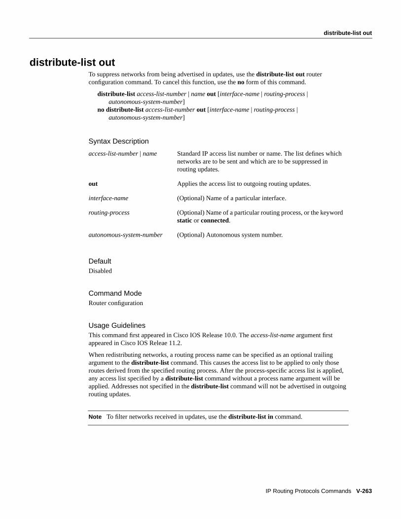
distribute-list outTo suppress networks from being advertised in updates, use the distribute-list out routerconfiguration command. To cancel this function, use theno form of this command.
distribute-list access-list-number| nameout [interface-name | routing-process |autonomous-system-number]
no distribute-list access-list-numberout [interface-name | routing-process |autonomous-system-number]
Syntax Description
DefaultDisabled
Command ModeRouter configuration
Usage GuidelinesThis command first appeared in Cisco IOS Release 10.0. Theaccess-list-name argument firstappeared in Cisco IOS Releae 11.2.
When redistributing networks, a routing process name can be specified as an optional trailingargument to thedistribute-list command. This causes the access list to be applied to only thoseroutes derived from the specified routing process. After the process-specific access list is applied,any access list specified by adistribute-list command without a process name argument will beapplied. Addresses not specified in thedistribute-list command will not be advertised in outgoingrouting updates.
Note To filter networks received in updates, use thedistribute-list in command.
access-list-number | name Standard IP access list number or name. The list defines whichnetworks are to be sent and which are to be suppressed inrouting updates.
out Applies the access list to outgoing routing updates.
interface-name (Optional) Name of a particular interface.
routing-process (Optional) Name of a particular routing process, or the keywordstatic or connected.
autonomous-system-number (Optional) Autonomous system number.

V-264 Network Protocols Command Reference, Part 1
distribute-list out
ExamplesThe following example would cause only one network to be advertised by a RIP routing process:network 131.108.0.0.
access-list 1 permit 131.108.0.0access-list 1 deny 0.0.0.0 255.255.255.255router ripnetwork 131.108.0.0distribute-list 1 out
In the following example, access list 1 is applied to outgoing routing updates and IS-IS is enabledon Ethernet interface 0. Only network 131.131.101.0 will be advertised in outgoing IS-IS routingupdates.
router isisredistribute ospf 109distribute-list 1 outinterface Ethernet 0ip router isisaccess-list 1 permit 131.131.101.0 0.0.0.255
Related CommandsA dagger (†) indicates that the command is documented outside this chapter.
access-list (extended)†
access-list (standard)†
distribute-list inredistribute

domain-password
IP Routing Protocols Commands V-265
domain-passwordTo configure the IS-IS routing domain authentication password, use thedomain-password routerconfiguration command. To disable a password, use theno form of this command.
domain-passwordpasswordno domain-password [password]
Syntax Description
DefaultNo password is specified.
Command ModeRouter configuration
Usage GuidelinesThis command first appeared in Cisco IOS Release 10.0.
This password is inserted in Level 2 (area router level) link state PDUs (LSPs), complete sequencenumber PDUs (CSNPs), and partial sequence number PDUs (PSNPs).
ExampleThe following example assigns an authentication password to the routing domain:
router isisdomain-password flower
Related Commandarea-password
password Password you assign.

V-266 Network Protocols Command Reference, Part 1
ip as-path access-list
ip as-path access-listTo define a BGP-related access list, use theip as-path access-list global configuration command.To disable use of the access list, use theno form of this command.
ip as-path access-listaccess-list-number{ permit | deny} as-regular-expressionno ip as-path access-listaccess-list-number{ permit | deny} as-regular-expression
Syntax Description
DefaultNo access lists are defined.
Command ModeGlobal configuration
Usage GuidelinesThis command first appeared in This command first appeared in Cisco IOS Release IOSRelease 10.0.
You can specify an access list filter on both inbound and outbound BGP routes. In addition, you canassignweights based on a set of filters. Each filter is an access list based on regular expressions. Ifthe regular expression matches the representation of the autonomous system path of the route as anASCII string, then thepermit or deny condition applies. The autonomous system path does notcontain the local autonomous system number. Use theip as-path access-list global configurationcommand to define an BGP access list, and theneighbor router configuration command to apply aspecific access list.
ExampleThe following example specifies that the BGP neighbor with IP address 128.125.1.1 is not sentadvertisements about any path through or from the adjacent autonomous system 123:
ip as-path access-list 1 deny _123_ip as-path access-list 1 deny ^123$
router bgp 109network 131.108.0.0neighbor 129.140.6.6 remote-as 123neighbor 128.125.1.1 remote-as 47neighbor 128.125.1.1 filter-list 1 out
access-list-number Integer from 1 to 199 that indicates the regular expression access listnumber.
permit Permits access for matching conditions.
deny Denies access to matching conditions.
as-regular-expression Autonomous system in the access list using a regular expression. Seethe “Regular Expressions” appendix in theAccess Services CommandReference for information about forming regular expressions.

ip as-path access-list
IP Routing Protocols Commands V-267
Related Commandsneighbor distribute-listneighbor filter-list

V-268 Network Protocols Command Reference, Part 1
ip bandwidth-percent eigrp
ip bandwidth-percent eigrpTo configure the percentage of bandwidth that may be used by enhanced IGRP on an interface, usetheip bandwidth-percent eigrp interface configuration command. To restore the default value, usetheno form of this command.
ip bandwidth-percent eigrp as-number percentno ip bandwidth-percent eigrp as-number percent
Syntax Description
Default50 percent
Command ModeInterface configuration
Usage GuidelinesThis command first appeared in Cisco IOS Release 11.2.
Enhanced IGRP will use up to 50 percent of the bandwidth of a link, as defined by thebandwidthinterface configuration command. This command may be used if some other fraction of thebandwidth is desired. Note that values greater than 100 percent may be configured; this may beuseful if the bandwidth is set artificially low for other reasons.
ExampleThe following example allows enhanced IGRP to use up to 75 percent (42 kbps) of a 56-kbps serial linkin autonomous system 209:
interface serial 0bandwidth 56ip bandwidth-percent eigrp 209 75
Related CommandA dagger (†) indicates that the command is documented outside this chapter.
bandwidth †
as-number Autonomous system number.
percent Percent of bandwidth that enhanced IGRP may use.

ip cgmp
IP Routing Protocols Commands V-269
ip cgmpTo enable CGMP routing on an interface, use theip cgmp interface configuration command. Todisable CGMP routing, use theno form of this command.
ip cgmp [priority number | reporttime seconds | holdtime seconds] proxyno ip cgmp
Syntax Description
Command ModeInterface configuration
Usage GuidelinesThis command first appeared in Cisco IOS Release 11.2.
When enabled on an interface, this command triggers a CGMP join message. This should only beused on 802.3 media. When ano ip cgmpcommand is issued, a triggered CGMP leave message issent for the router’s MAC address on the interface for group 000.000.000.
ExampleIn the following example, CGMP is enabled on Ethernet interface 1 with a report time of 10 seconds,and priority and hold time set to their defaults (because none are specified):
ip cgmp reporttime 10
priority number (Optional) Alters the CGMP priority. A larger number indicatesa higher priority.
reporttime seconds (Optional) Alters the CGMP reporting interval; the default is5 seconds for broadcast media such as Ethernets, and never fornonbroadcast media such as X.25.
holdtime seconds (Optional) Alters the CGMP default hold time of 15 seconds.
proxy (Optional) Enables CGMP for IP as well as the DVMRP proxyfunction.
V-270 Network Protocols Command Reference, Part 1
ip community-list
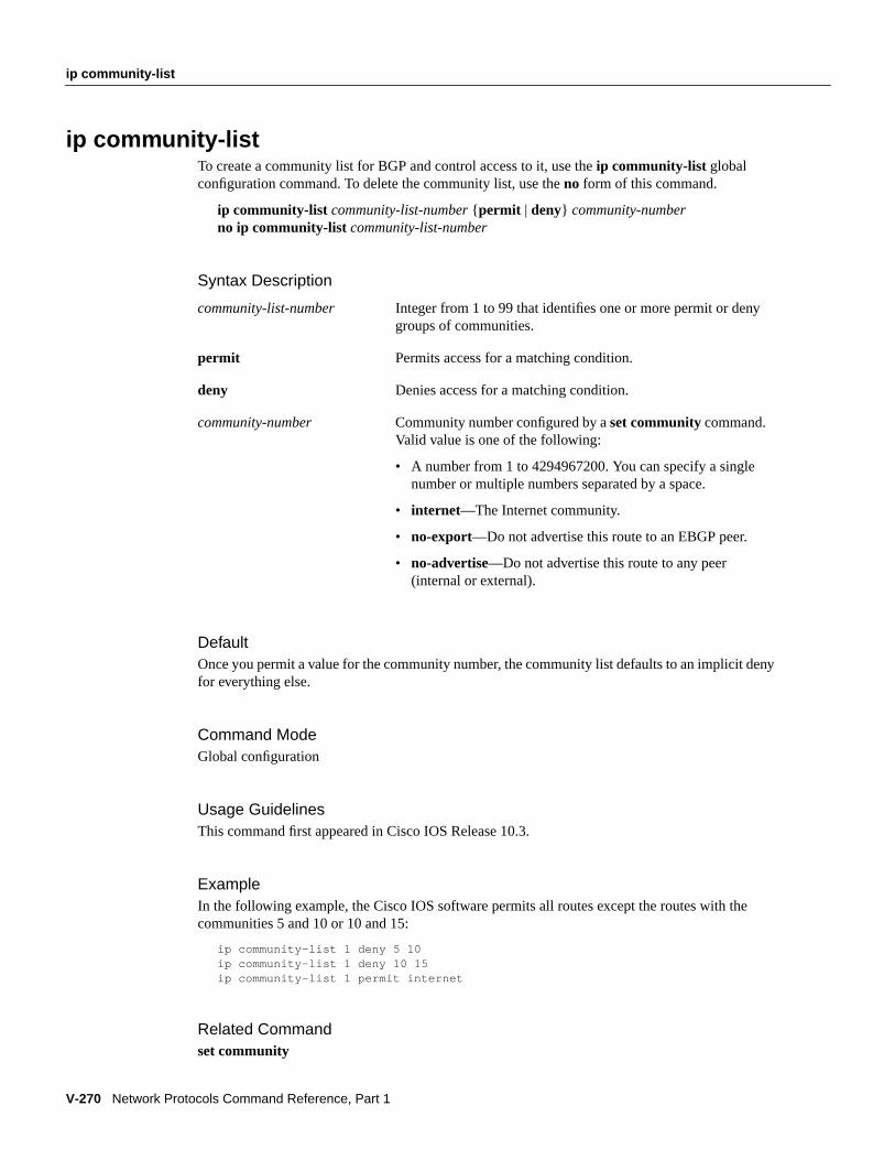
ip community-listTo create a community list for BGP and control access to it, use theip community-list globalconfiguration command. To delete the community list, use theno form of this command.
ip community-list community-list-number {permit | deny} community-numberno ip community-list community-list-number
Syntax Description
DefaultOnce you permit a value for the community number, the community list defaults to an implicit denyfor everything else.
Command ModeGlobal configuration
Usage GuidelinesThis command first appeared in Cisco IOS Release 10.3.
ExampleIn the following example, the Cisco IOS software permits all routes except the routes with thecommunities 5 and 10 or 10 and 15:
ip community-list 1 deny 5 10ip community-list 1 deny 10 15ip community-list 1 permit internet
Related Commandset community
community-list-number Integer from 1 to 99 that identifies one or more permit or denygroups of communities.
permit Permits access for a matching condition.
deny Denies access for a matching condition.
community-number Community number configured by aset community command.Valid value is one of the following:
• A number from 1 to 4294967200. You can specify a singlenumber or multiple numbers separated by a space.
• internet—The Internet community.
• no-export—Do not advertise this route to an EBGP peer.
• no-advertise—Do not advertise this route to any peer(internal or external).

ip default-network
IP Routing Protocols Commands V-271
ip default-networkTo select a network as a candidate route for computing the gateway of last resort, use theip default-network global configuration command. To remove a route, use theno form of thiscommand.
ip default-network network-numberno ip default-network network-number
Syntax Description
DefaultIf the router has a directly connected interface onto the specified network, the dynamic routingprotocols running on that router will generate (or source) a default route. For RIP, this is flagged asthe pseudonetwork 0.0.0.0; for IGRP, it is the network itself, flagged as an exterior route.
Command ModeGlobal configuration
Usage GuidelinesThis command first appeared in Cisco IOS Release 10.0.
The Cisco IOS software uses both administrative distance and metric information to determine thedefault route. Multipleip default-network commands can be given. All candidate default routes,both static (that is, flagged byip default-network) and dynamic, appear in the routing tablepreceded by an asterisk.
If the IP routing table indicates that the specified network number is subnetted and a non-zero subnetnumber is specified, then the system will automatically configure a static summary route. This staticsummary route is configured instead of a default network. The effect of the static summary route isto cause traffic destined for subnets that are not explicitly listed in the IP routing table to be routedusing the specified subnet.
ExamplesThe following example defines a static route to network 10.0.0.0 as the static default route:
ip route 10.0.0.0 255.0.0.0 131.108.3.4ip default-network 10.0.0.0
If the following command was issued on a router not connected to network 129.140.0.0, the softwaremight choose the path to that network as a default route when the network appeared in the routingtable:
ip default-network 129.140.0.0
Related Commandshow ip route
network-number Number of the network.

V-272 Network Protocols Command Reference, Part 1
ip dvmrp accept-filter
ip dvmrp accept-filterTo configure an acceptance filter for incoming DVMRP reports, use theip dvmrp accept-filterinterface configuration command. To disable this feature, use theno form of this command.
ip dvmrp accept-filter access-list-number[distance] neighbor-list access-list-numberno ip dvmrp accept-filter access-list-number[distance] neighbor-list access-list-number
Syntax Description
DefaultAll destination reports are accepted with a distance of 0. Default settings accept reports from allneighbors.
Command ModeInterface configuration
Usage GuidelinesThis command first appeared in Cisco IOS Release 10.0. Theneighbor-list keyword andaccess-list-number argument first appeared in Cisco IOS 11.2.
Any sources that match the access list are stored in the DVMRP routing table withdistance.
Thedistance is used to compare with the same source in the unicast routing table. The route with thelower distance (either the route in the unicast routing table or that in the DVMRP routing table) takesprecedence when computing the Reverse Path Forwarding (RPF) interface for a source of a multicastpacket.
By default, the administrative distance for DVMRP routes is 0. This means that they always takeprecedence over unicast routing table routes. If you have two paths to a source, one through unicastrouting (using PIM as the multicast routing protocol) and another path using DVMRP (unicast andmulticast routing), and if you want to use the PIM path, use theip dvmrp accept-filter command toincrease the administrative distance for DVMRP routes. For example, if the unicast routing protocolis Enhanced IGRP, which has a default administrative distance of 90, you could define and apply thefollowing access list so the RPF interface used to accept multicast packets will be through theEnhanced IGRP/PIM path:
ip dvmrp accept-filter 1 100access-list 1 permit 0.0.0.0 255.255.255.255
access-list-number Number of a standard IP access list. This can be a number from0 to 99. A value of 0 means that all sources are accepted withthe configured distance.
neighbor-listaccess-list number
Number of a neighbor list. DVMRP reports are accepted onlyby those neighbors on the list.
distance (Optional) Administrative distance to the destination.
ip dvmrp accept-filter
IP Routing Protocols Commands V-273
ExampleThe following example applies access list 57 to the interface and sets a distance of 4:
access-list 57 permit 131.108.0.0 0.0.255.255access-list 57 permit 198.92.37.0 0.0.0.255access-list 57 deny 0.0.0.0 255.255.255.255ip dvmrp accept-filter 57 4
Related CommandsA dagger (†) indicates that the command is documented outside this chapter.
distanceip dvmrp metricshow ip dvmrp routetunnel mode†

V-274 Network Protocols Command Reference, Part 1
ip dvmrp default-information
ip dvmrp default-informationTo advertise network 0.0.0.0 to DVMRP neighbors on an interface, use theip dvmrpdefault-information interface configuration command. To prevent the advertisement, use thenoform of this command.
ip dvmrp default-information { originate | only}no ip dvmrp default-information { originate | only}
Syntax Description
DefaultDisabled
Command ModeInterface configuration
Usage GuidelinesThis command first appeared in Cisco IOS Release 10.3.
This command should only be used when the router is a neighbor to mrouted version 3.6 machines.The mrouted protocol is a public domain implementation of DVMRP.
You can use theip dvmrp metric command with theip dvmrp default-information command totailor the metric used when advertising the default route 0.0.0.0. By default, metric 1 is used.
ExampleThe following example configures the Cisco IOS software to advertise network 0.0.0.0, in additionto other networks, to DVMRP neighbors:
ip dvmrp default-information originate
Related Commandip dvmrp metric
originate Other routes more specific than 0.0.0.0 can also be advertised.
only No DVMRP routes other than 0.0.0.0 are advertised.
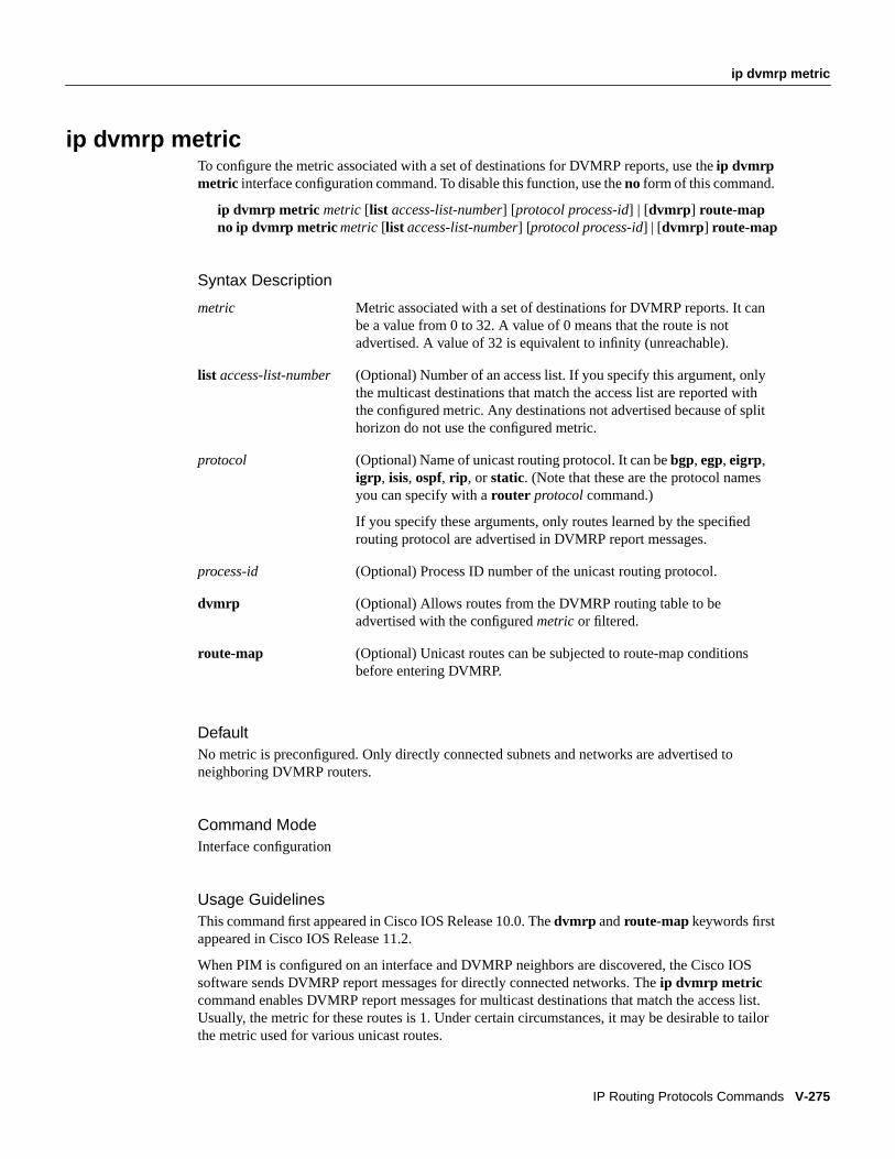
ip dvmrp metric
IP Routing Protocols Commands V-275
ip dvmrp metricTo configure the metric associated with a set of destinations for DVMRP reports, use theip dvmrpmetric interface configuration command. To disable this function, use theno form of this command.
ip dvmrp metric metric [list access-list-number] [protocol process-id] | [dvmrp ] route-mapno ip dvmrp metric metric [list access-list-number] [protocol process-id] | [dvmrp ] route-map
Syntax Description
DefaultNo metric is preconfigured. Only directly connected subnets and networks are advertised toneighboring DVMRP routers.
Command ModeInterface configuration
Usage GuidelinesThis command first appeared in Cisco IOS Release 10.0. Thedvmrp and route-mapkeywords firstappeared in Cisco IOS Release 11.2.
When PIM is configured on an interface and DVMRP neighbors are discovered, the Cisco IOSsoftware sends DVMRP report messages for directly connected networks. Theip dvmrp metriccommand enables DVMRP report messages for multicast destinations that match the access list.Usually, the metric for these routes is 1. Under certain circumstances, it may be desirable to tailorthe metric used for various unicast routes.
metric Metric associated with a set of destinations for DVMRP reports. It canbe a value from 0 to 32. A value of 0 means that the route is notadvertised. A value of 32 is equivalent to infinity (unreachable).
list access-list-number (Optional) Number of an access list. If you specify this argument, onlythe multicast destinations that match the access list are reported withthe configured metric. Any destinations not advertised because of splithorizon do not use the configured metric.
protocol (Optional) Name of unicast routing protocol. It can bebgp, egp, eigrp,igrp , isis, ospf, rip , orstatic. (Note that these are the protocol namesyou can specify with arouter protocol command.)
If you specify these arguments, only routes learned by the specifiedrouting protocol are advertised in DVMRP report messages.
process-id (Optional) Process ID number of the unicast routing protocol.
dvmrp (Optional) Allows routes from the DVMRP routing table to beadvertised with the configuredmetric or filtered.
route-map (Optional) Unicast routes can be subjected to route-map conditionsbefore entering DVMRP.

V-276 Network Protocols Command Reference, Part 1
ip dvmrp metric
Use theaccess-list-number argument in conjunction with theprotocol process-id arguments toselectively list the destinations learned from a given routing protocol.
To display DVMRP activity, use thedebug ip dvmrp command.
ExampleThe following example connects a PIM cloud to a DVMRP cloud. Access list 1 permits the sendingof DVMRP reports to the DVMRP routers advertising all sources in the 198.92.35.0 network with ametric of 1. Access list 2 permits all other destinations, but the metric of 0 means that no DVMRPreports are sent for these destinations.
access-list 1 permit 198.92.35.0 0.0.0.255access-list 1 deny 0.0.0.0 255.255.255.255access-list 2 permit 0.0.0.0 255.255.255.255interface tunnel 0ip dvmrp metric 1 list 1ip dvmrp metric 0 list 2
Related CommandsTwo daggers (††) indicate that the command is documented in theDebug Command Reference.
debug ip dvmrp ††
ip dvmrp accept-filter

ip gdp
IP Routing Protocols Commands V-277
ip gdpTo enable GDP routing on an interface, use theip gdp interface configuration command. To disableGDP routing, use theno form of this command.
ip gdp [priority number | reporttime seconds | holdtime seconds]no ip gdp
Syntax Description
Defaultspriority : 100reporttime : 5 seconds for broadcast media; 0 for nonbroadcast mediaholdtime: 15 seconds
Command ModeInterface configuration
Usage GuidelinesThis command first appeared in Cisco IOS Release 10.3.
When enabled on an interface, GDP updates report the primary and secondary IP addresses of thatinterface.
Note In future Cisco IOS software releases the Gateway Discovery Protocol will not be supported.
ExampleIn the following example, GDP is enabled on Ethernet interface 1 with a report time of 10 seconds,and priority and hold time set to their defaults (because none are specified):
ip gdp reporttime 10
priority number (Optional) Alters the GDP priority; default is a priority of 100.A larger number indicates a higher priority.
reporttime seconds (Optional) Alters the GDP reporting interval; the default is5 seconds for broadcast media such as Ethernets, and never fornonbroadcast media such as X.25.
holdtime seconds (Optional) Alters the GDP default hold time of 15 seconds.

V-278 Network Protocols Command Reference, Part 1
ip hello-interval eigrp
ip hello-interval eigrpTo configure the hello interval for the Enhanced IGRP routing process designated by an autonomoussystem number, use theip hello-interval eigrp interface configuration command. To restore thedefault value, use theno form of this command.
ip hello-interval eigrp autonomous-system-number secondsno ip hello-interval eigrp autonomous-system-number seconds
Syntax Description
DefaultsFor low-speed, NBMA networks: 60 secondsFor all other networks: 5 seconds
Command ModeInterface configuration
Usage GuidelinesThis command first appeared in Cisco IOS Release 10.0.
The default of 60 seconds applies only to low-speed, nonbroadcast, multiaccess (NBMA) media.Low speed is considered to be a rate of T1 or slower, as specified with thebandwidth interfaceconfiguration command. Note that for the purposes of Enhanced IGRP, Frame Relay and SMDSnetworks may or may not be considered to be NBMA. These networks are considered NBMA if theinterface has not been configured to use physical multicasting; otherwise they are considered not tobe NBMA.
ExampleThe following example sets the hello interval for Ethernet interface 0 to 10 seconds:
interface ethernet 0ip hello-interval eigrp 109 10
Related Commandip hold-time eigrp
autonomous-system-number Autonomous system number.
seconds Hello interval, in seconds.

ip hold-time eigrp
IP Routing Protocols Commands V-279
ip hold-time eigrpTo configure the hold time for a particular Enhanced IGRP routing process designated by theautonomous system number, use theip hold-time eigrp interface configuration command. Torestore the default value, use theno form of this command.
ip hold-time eigrp autonomous-system-number secondsno ip hold-time eigrp autonomous-system-number seconds
Syntax Description
DefaultsFor low-speed, NBMA networks: 180 secondsFor all other networks: 15 seconds
Command ModeInterface configuration
Usage GuidelinesThis command first appeared in Cisco IOS Release 10.0.
On very congested and large networks, the default hold time might not be sufficient time for allrouters and access servers to receive hello packets from their neighbors. In this case, you may wantto increase the hold time.
The hold time is three times the hello interval. If the current value for the hold time is less than twotimes the hello interval, the hold time is reset.
If a router does not receive a hello packet within the specified hold time, routes through this routerare considered unavailable.
Increasing the hold time delays route convergence across the network.
The default of 180 seconds applies only to low-speed, nonbroadcast, multiaccess (NBMA) media.Low speed is considered to be a rate of T1 or slower, as specified with thebandwidth interfaceconfiguration command.
ExampleThe following example sets the hold time for Ethernet interface 0 to 40 seconds:
interface ethernet 0ip hold-time eigrp 109 40
Related Commandip hello-interval eigrp
autonomous-system-number Autonomous system number.
seconds Hold time, in seconds.

V-280 Network Protocols Command Reference, Part 1
ip igmp access-group
ip igmp access-groupTo control the multicast groups that hosts on the subnet serviced by an interface can join, use theip igmp access-group interface configuration command. To disable groups on an interface, use theno form of this command.
ip igmp access-groupaccess-list-number versionno ip igmp access-groupaccess-list-number version
Syntax Description
DefaultAll groups are allowed on an interface.
Command ModeInterface configuration
Usage GuidelinesThis command first appeared in Cisco IOS Release 10.0.
ExampleIn the following example, hosts serviced by Ethernet interface 0 can join the group 225.2.2.2 only:
access-list 1 225.2.2.2 0.0.0.0interface ethernet 0ip igmp access-group 1
Related Commandip igmp join-group
access-list-number Number of a standard IP access list. This can be a number from1 to 99.
version Changes IGMP version. Default is version 2.

ip igmp join-group
IP Routing Protocols Commands V-281
ip igmp join-groupTo have the router join a multicast group, use theip igmp join-group interface configurationcommand. To cancel membership in a multicast group, use theno form of this command.
ip igmp join-group group-addressno ip igmp join-group group-address
Syntax Description
DefaultNo multicast group memberships are predefined.
Command ModeInterface configuration
Usage GuidelinesThis command first appeared in Cisco IOS Release 10.0.
IP packets that are addressed to the group address are passed to the IP client process in the Cisco IOSsoftware.
If all the multicast-capable routers and access servers that you administer are members of a multicastgroup, pinging that group causes all routers to respond. This can be a useful administrative anddebugging tool.
Another reason to have a router join a multicast group is when other hosts on the network have a bugin IGRP that prevents them from correctly answering IGMP queries. Having the router join themulticast group causes upstream routers to maintain multicast routing table information for thatgroup and keep the paths for that group active.
ExampleIn the following example, the router joins multicast group 225.2.2.2:
ip igmp join-group 225.2.2.2
Related CommandsA dagger (†) indicates that the command is documented outside this chapter.
ip igmp access-groupping (privileged) †
ping (user)†
group-address Address of the multicast group. This is a multicast IP address infour-part, dotted notation.

V-282 Network Protocols Command Reference, Part 1
ip igmp query-interval
ip igmp query-intervalTo configure the frequency at which the Cisco IOS software sends IGMP host-query messages, usetheip igmp query-interval interface configuration command. To return to the default frequency, usetheno form of this command.
ip igmp query-interval secondsno ip igmp query-interval
Syntax Description
Default60 seconds
Command ModeInterface configuration
Usage GuidelinesThis command first appeared in Cisco IOS Release 10.0.
Multicast routers send host membership query messages (referred to as host-query messages) todiscover which multicast groups have members on the router’s attached networks. Hosts respondwith IGMP report messages indicating that they wish to receive multicast packets for specific groups(that is, indicating that the host wants to become a member of the group). Host-query messages areaddresses to the all-hosts multicast group, which has the address 224.0.0.1, and have an IP TTL valueof 1.
The designated router for a LAN is the only router that sends IGMP host-query messages. Thedesignated router is elected according to the multicast routing protocol that runs on the LAN. If therouter hears no queries for the timeout period, it becomes the querier.
Note Changing this value may severely impact multicast forwarding.
ExampleThe following example changes the frequency at which the designated router sends IGMPhost-query messages to 2 minutes:
interface tunnel 0ip igmp query-interval 120
Related Commandsip pim query-intervalshow ip igmp groups
seconds Frequency, in seconds, at which to transmit IGMP host-querymessages. The can be a number from 0 to 65535. The default is60 seconds.

ip igmp query-max-response-time
IP Routing Protocols Commands V-283
ip igmp query-max-response-timeTo configure the maximum response time advertised in the IGMP queries, use theip igmpquery-max-response-time interface configuration command. To return to the default frequency, usetheno form of this command.
ip igmp query-max-response timesecondsno ip igmp query-max-response-time
Syntax Description
Default10 seconds
Command ModeInterface configuration
Usage GuidelinesThis command first appeared in Cisco IOS Release 11.2.
Configuring a value less than 10 seconds enables the router to prune groups faster.
Related Commandsip pim query-intervalshow ip igmp groups
seconds Frequency, in seconds, of the maximum response timeadvertised in the IGMP queries.

V-284 Network Protocols Command Reference, Part 1
ip irdp
ip irdpTo enable ICMP Router Discovery Protocol (IRDP) processing on an interface, use theip irdpinterface configuration command. To disable IRDP routing, use theno form of this command.
ip irdp [multicast | holdtime seconds | maxadvertinterval seconds | minadvertintervalseconds | preferencenumber | addressaddress [number]]
no ip irdp
Syntax Description
DefaultDisabled
When enabled, IRDP uses these defaults:
• Broadcast IRDP advertisements
• Maximum interval between advertisements: 600 seconds
• Minimum interval between advertisements: 0.75 timesmaxadvertinterval
• Preference: 0
Command ModeInterface configuration
Usage GuidelinesThis command first appeared in Cisco IOS Release 10.0.
multicast (Optional) Use the multicast address (224.0.0.1) instead of IPbroadcasts.
holdtime seconds (Optional) Length of time in seconds advertisements are heldvalid. Default is three times themaxadvertinterval value. Mustbe greater thanmaxadvertinterval and cannot be greater than9000 seconds.
maxadvertinterval seconds (Optional) Maximum interval in seconds betweenadvertisements. The default is 600 seconds.
minadvertinterval seconds (Optional) Minimum interval in seconds betweenadvertisements. The default is 0.75 times themaxadvertinterval. If you change themaxadvertintervalvalue, this value defaults to three-quarters of the new value.
preference number (Optional) Preference value. The allowed range is -231 to 231.The default is 0. A higher value increases the router’spreference level. You can modify a particular router so that itwill be the preferred router to which others home.
address address[number] (Optional) IP address (address) to proxy-advertise, andoptionally, its preference value (number).

ip irdp
IP Routing Protocols Commands V-285
If you changemaxadvertinterval, the other two values also change, so it is important to changemaxadvertinterval first before changing eitherholdtime or minadvertinterval .
The ip irdp multicast command allows for compatibility with Sun Microsystems Solaris, whichrequires IRDP packets to be sent out as multicasts. Many implementations cannot receive thesemulticasts; ensure end-host ability before using this command.
ExampleThe following example illustrates how to set the various IRDP processes:
! enable irdp on interface Ethernet 0interface ethernet 0ip irdp! send IRDP advertisements to the multicast addressip irdp multicast! increase router preference from 100 to 50ip irdp preference 50! set maximum time between advertisements to 400 secsip irdp maxadvertinterval 400! set minimum time between advertisements to 100 secsip irdp minadvertinterval 100! advertisements are good for 6000 secondsip irdp holdtime 6000! proxy-advertise 131.108.14.5 with default router preferenceip irdp address 131.108.14.5! proxy-advertise 131.108.14.6 with preference of 50ip irdp address 131.108.14.6 50

V-286 Network Protocols Command Reference, Part 1
ip local policy route-map
ip local policy route-mapTo identify a route map to use for local policy routing, use theip local policy route-mapglobalconfiguration command. To disable local policy routing, use theno form of this command.
ip local policy route-mapmap-tagno ip local policy route-mapmap-tag
Syntax Description
DefaultPackets that are generated by the router are not policy-routed.
Command ModeGlobal configuration
Usage GuidelinesThis command first appeared in Cisco IOS Release 11.1
Packets that are generated by the router are not normally policy-routed. However, you can use thiscommand to policy-route such packets. You might enable local policy routing if you want packetsoriginated at the router to take a route other than the obvious shortest path.
Theip local policy route-map command identifies a route map to use for local policy routing. Eachroute-map command has a list ofmatch andset commands associated with it. Thematchcommands specify thematch criteria—the conditions under which packets should be policy-routed.Theset commands specify theset actions—the particular policy routing actions to perform if thecriteria enforced by thematch commands are met. Theno ip local policy route-mapcommanddeletes the reference to the route map and disables local policy routing.
ExampleIn the following example, packets with a destination IP address matching that allowed by extendedaccess list 131 are sent to the router at IP address 174.21.3.20:
ip local policy route-map xxx!route-map xxxmatch ip address 131set ip next-hop 174.21.3.20
map-tag Name of the route map to use for local policy routing. The name mustmatch amap-tag specified by aroute-map command.

ip local policy route-map
IP Routing Protocols Commands V-287
Related Commandsmatch ip addressmatch lengthroute-mapset default interfaceset interfaceset ip default next-hopset ip next-hopshow ip local policy

V-288 Network Protocols Command Reference, Part 1
ip mroute
ip mrouteTo configure a multicast static route (mroute), use the ip mrouteglobal configuration command. Toremove the route, use theno form of this command.
ip mroute source mask [protocol as-number] { rpf-address | interface} [ distance]no ip mroute source mask [protocol as-number] { rpf-address | interface} [ distance]
Syntax Description
Defaultdistance: 0
Command ModeGlobal configuration
Usage GuidelinesThis command first appeared in Cisco IOS Release 11.0.
This command allows you to statically configure where multicast sources are located (even thoughthe unicast routing table says something different).
When a source range is specified, therpf-address applies only to those sources.
source IP address of the multicast source.
mask Mask on the IP address of the multicast source.
protocol (Optional) Unicast routing protocol that you are using.
as-number (Optional) Autonomous system number of the routing protocol you areusing, if applicable.
rpf-address Incoming interface for the mroute. If the Reverse Path Forwardingaddressrpf-addressis a PIM neighbor, PIM Joins, Grafts, and Prunesare sent to it. Therpf-address can be a host IP address of a directlyconnected system or a network/subnet number. When it is a route, arecursive lookup is done from the unicast routing table to find adirectly connected system. Ifrpf-address is not specified, the interfacetype numberis used as the incoming interface.
interface Interface type and number for the mroute.
distance (Optional) Determines whether a unicast route, a DVMRP route, or astatic mroute should be used for the RPF lookup. The lower distanceshave better preference. If the static mroute has the same distance as theother two RPF sources, the static mroute will take precedence. Thedefault is 0.

ip mroute
IP Routing Protocols Commands V-289
ExamplesThe following example configures all sources via a single interface (in this case, a tunnel):
ip mroute 0.0.0.0 255.255.255.255 tunnel0
The following example configures all specific sources within a network number are reachablethrough 171.68.10.13:
ip mroute 171.69.0.0 255.255.0.0 171.68.10.13
The following example causes this multicast static route to take effect if the unicast routes for anygiven destination go away:
ip mroute 0.0.0.0 255.255.255.255 serial0 200

V-290 Network Protocols Command Reference, Part 1
ip mroute-cache
ip mroute-cacheTo configure IP multicast fast switching, use theip mroute-cacheinterface configuration command.To disable IP multicast fast switching, use theno form of this command.
ip mroute-cacheno ip mroute-cache
Syntax DescriptionThis command has no arguments or keywords.
DefaultEnabled
Command ModeInterface configuration
Usage GuidelinesThis command first appeared in Cisco IOS Release 11.0.
If fast switching is disabled on an incoming interface for a multicast routing table entry, the packetwill be sent at process level for all interfaces in the outgoing interface list.
If fast switching is disabled on an outgoing interface for a multicast routing table entry, the packetis process level switched for that interface, but might be fast-switched for other interfaces in theoutgoing interface list.
When fast switching is enabled (like unicast routing), debug messages are not logged. If you wantto log debug messages, disable fast switching.
ExampleThe following example disables IP multicast fast switching on the interface:
no ip mroute-cache

ip multicast rate-limit
IP Routing Protocols Commands V-291
ip multicast rate-limitTo control the rate a sender from the source-list can send to a multicast group in the group-list, usetheip multicast rate-limit interface configuration command. To remove the control, use theno formof this command.
ip multicast rate-limit { in | out} [ group-list access-list] [source-listaccess-list] kbpsno multicast rate-limit { in | out} [ group-list access-list] [source-listaccess-list] kbps
Syntax Description
Defaultkbps = 0, meaning that there is no limit on the rate traffic is sent.
Command ModeInterface configuration
Usage GuidelinesThis command first appeared in Cisco IOS Release 11.0.
If a router receives a packet and in the last second the user has sent over the limit, the packet isdropped; otherwise, it is forwarded.
ExampleIn the following example, packets to any group from sources in network 171.69.0.0 will have theirpackets rate-limited to 64 kbps:
interface serial 0ip multicast rate-limit out group-list 1 source-list 2 64access-list 1 permit 0.0.0.0 255.255.255.255access-list 2 permit 171.69.0.0 0.0.255.255
in Only packets at the rate ofkbps or slower are accepted on the interface.
out Only a maximum ofkbps will be transmitted on the interface.
group-list access-list (Optional) Specifies the access list number that controls whichmulticast groups are subject to the rate limit.
source-listaccess-list (Optional) Specifies the access list number that controls which sendersare subject to the rate limit.
kbps Kilobits-per-second transmission rate.

V-292 Network Protocols Command Reference, Part 1
ip multicast-routing
ip multicast-routingTo enable IP multicast routing, use theip multicast-routing global configuration command. Todisable IP multicast routing, use theno form of this command.
ip multicast-routingno ip multicast-routing
Syntax DescriptionThis command has no arguments or keywords.
DefaultDisabled
Command ModeGlobal configuration
Usage GuidelinesThis command first appeared in Cisco IOS Release 10.0.
When IP multicast routing is disabled, the Cisco IOS software does not forward any multicastpackets.
ExampleThe following example enables IP multicast routing:
ip multicast-routing
Related Commandip pim

ip multicast ttl-threshold
IP Routing Protocols Commands V-293
ip multicast ttl-thresholdTo configure the time-to-live (TTL) threshold of packets being forwarded out an interface, use theip multicast ttl-thr eshold interface configuration command. To return to the default TTL threshold,use theno form of this command.
ip multicast ttl-threshold ttl-valueno ip multicast ttl-threshold [ttl-value]
Syntax Description
Default0, which means that all multicast packets are forwarded out the interface.
Command ModeInterface configuration
Usage GuidelinesThis command first appeared in Cisco IOS Release 11.0.
Only multicast packets with a TTL value greater than the threshold are forwarded out the interface.
You should configure the TTL threshold only on border routers. Conversely, routers on which youconfigure a TTL threshold value automatically become border routers.
This command replaces theip multicast-threshold command, which is obsolete.
ExampleIn the following example, you set the TTL threshold on a border router to 200, which is a very highvalue. This means that multicast packets must have a TTL greater than 200 in order to be forwardedout this interface. Multicast applications generally set this value well below 200. Therefore, settinga value of 200 means that no packets will be forwarded out the interface.
interface tunnel 0ip multicast ttl-threshold 200
Related Commandsip ospf authentication-keyip ospf message-digest-key
ttl-value Time-to-live value, in hops. It can be a value from 0 to 255. Thedefault value is 0, which means that all multicast packets areforwarded out the interface.

V-294 Network Protocols Command Reference, Part 1
ip ospf authentication-key
ip ospf authentication-keyTo assign a password to be used by neighboring routers that are using OSPF’s simple passwordauthentication, use the ip ospf authentication-keyinterface configuration command. To remove apreviously assigned OSPF password, use theno form of this command.
ip ospf authentication-keypasswordno ip ospf authentication-key
Syntax Description
DefaultNo password is specified.
Command ModeInterface configuration
Usage GuidelinesThis command first appeared in Cisco IOS Release 10.0.
The password created by this command is used as a “key” that is inserted directly into the OSPFheader when the Cisco IOS software originates routing protocol packets. A separate password canbe assigned to each network on a per-interface basis. All neighboring routers on the same networkmust have the same password to be able to exchange OSPF information.
Note The Cisco IOS software will use this key only when authentication is enabled for an area withthearea authentication router configuration command.
ExampleIn the following example, the authentication key is enabled with the stringyourpass:
ip ospf authentication-key yourpass
Related Commandarea authentication
password Any continuous string of characters that can be entered from thekeyboard up to 8 bytes in length.

ip ospf cost
IP Routing Protocols Commands V-295
ip ospf costTo explicitly specify the cost of sending a packet on an interface, use the ip ospf costinterfaceconfiguration command. To reset the path cost to the default value, use theno form of this command.
ip ospf costcostno ip ospf cost
Syntax Description
DefaultNo default cost is predefined.
Command ModeInterface configuration
Usage GuidelinesThis command first appeared in Cisco IOS Release 10.0.
Unlike IGRP, you must set this metric manually using this command, if you need to change thedefault. Changing the bandwidth does not change the link cost.
The link state metric is advertised as the link cost in the router link advertisement. We do not supporttype of service (TOS), so you can assign only one cost per interface.
In general, the path cost is calculated using the following formula:
108 ÖBandwidth
Using this formula, the default path costs were calculated as noted in the following list. If thesevalues do not suit your network, you can use your own method of calculating path costs.
• 56-kbps serial link—Default cost is 1785
• 64-kbps serial link—Default cost is 1562
• T1 (1.544-Mbps serial link)—Default cost is 65
• E1 (2.048-Mbps serial link)—Default cost is 48
• 4-Mbps Token Ring—Default cost is 25
• Ethernet—Default cost is 10
• 16-Mbps Token Ring—Default cost is 6
• FDDI—Default cost is 1
ExampleThe following example sets the interface cost value to 65:
ip ospf cost 65
cost Unsigned integer value expressed as the link state metric. It canbe a value in the range 1 to 65535.

V-296 Network Protocols Command Reference, Part 1
ip ospf dead-interval
ip ospf dead-intervalTo set how long hello packets must not have been seen before its neighbors declare the router down,use the ip ospf dead-intervalinterface configuration command. To return to the default time, usetheno form of this command.
ip ospf dead-intervalsecondsno ip ospf dead-interval
Syntax Description
DefaultFour times the interval set by theip ospf hello-interval command
Command ModeInterface configuration
Usage GuidelinesThis command first appeared in Cisco IOS Release 10.0.
The interval is advertised in the router’s hello packets. This value must be the same for all routersand access servers on a specific network.
ExampleThe following example sets the OSPF dead interval to 60 seconds:
interface ethernet 1ip ospf dead-interval 60
Related Commandip ospf hello-interval
seconds Unsigned integer that specifies the interval in seconds; the valuemust be the same for all nodes on the network.

ip ospf demand-circuit
IP Routing Protocols Commands V-297
ip ospf demand-circuitTo configure OSPF to treat the interface as an OSPF demand circuit,use the ip ospf demand-circuitinterface configuration command. To remove the demand circuit designation from the interface, usetheno form of this command.
ip ospf demand-circuitno ip ospf demand-circuit
Syntax DescriptionThis command has no arguments or keywords.
DefaultThe circuit is not a demand circuit.
Command ModeInterface configuration
Usage GuidelinesThis command first appeared in Cisco IOS Release 11.2.
On point-to-point interfaces, only one end of the demand circuit must be configured with thiscommand. Periodic hellos are suppressed and periodic refreshes of LSAs do not flood the demandcircuit. It allows the underlying datalink layer to be closed when the topology is stable. Inpoint-to-multipoint topology, only the multipoint end must configured with this command.
ExampleThe following example sets the configures an ISDN on demand circuit:
router ospf1network 18.0.3.0.0.0.0.25 area 0interface BRIOip ospf demand-circuit

V-298 Network Protocols Command Reference, Part 1
ip ospf hello-interval
ip ospf hello-intervalTo specify the interval between hello packets that the Cisco IOS software sends on the interface, usethe ip ospf hello-interval interface configuration command. To return to the default time, use thenoform of this command.
ip ospf hello-interval secondsno ip ospf hello-interval
Syntax Description
Default10 seconds
Command ModeInterface configuration
Usage GuidelinesThis command first appeared in Cisco IOS Release 10.0.
This value is advertised in the hello packets. The smaller the hello interval, the faster topologicalchanges will be detected, but more routing traffic will ensue. This value must be the same for allrouters and access servers on a specific network.
ExampleThe following example sets the interval between hello packets to 15 seconds:
interface ethernet 1ip ospf hello-interval 15
Related Commandip ospf dead-interval
seconds Unsigned integer that specifies the interval in seconds. Thevalue must be the same for all nodes on a specific network.

ip ospf message-digest-key
IP Routing Protocols Commands V-299
ip ospf message-digest-keyTo enable OSPF MD5 authentication, use the ip ospf message-digest-keyinterface configurationcommand. To remove an old MD5 key, use theno form of this command.
ip ospf message-digest-keykeyidmd5 keyno ip ospf message-digest-keykeyid
Syntax Description
DefaultOSPF MD5 authentication is disabled.
Command ModeInterface configuration
Usage GuidelinesThis command first appeared in Cisco IOS Release 11.0.
Usually, one key per interface is used to generate authentication information when sending packetsand to authenticate incoming packets. The same key identifier on the neighbor router must have thesamekey value.
The process of changing keys is as follows. Suppose the current configuration is as follows:
interface ethernet 1ip ospf message-digest-key 100 md5 OLD
You change the configuration to the following:
interface ethernet 1ip ospf message-digest-key 101 md5 NEW
The system assumes its neighbors do not have the new key yet, so it begins a rollover process. Itsends multiple copies of the same packet, each authenticated by different keys. In this example, thesystem sends out two copies of the same packet—the first one authenticated by key 100 and thesecond one authenticated by key 101.
Rollover allows neighboring routers to continue communication while the network administrator isupdating them with the new key. Rollover stops once the local system finds that all its neighborsknow the new key. The system detects that a neighbor has the new key when it receives packets fromthe neighbor authenticated by the new key.
After all neighbors have been updated with the new key, the old key should be removed. In thisexample, you would enter the following:
interface ethernet 1no ip ospf message-digest-key 100
Then, only key 101 is used for authentication on Ethernet interface 1.
keyid An identifier in the range 1 to 255.
key Alphanumeric password of up to 16 bytes.

V-300 Network Protocols Command Reference, Part 1
ip ospf message-digest-key
We recommend that you not keep more than one key per interface. Every time you add a new key,you should remove the old key to prevent the local system from continuing to communicate with ahostile system that knows the old key. Removing the old key also reduces overhead during rollover.
ExampleThe following example sets a new key 19 with the password8ry4222:
interface ethernet 1ip ospf message-digest-key 10 md5 xvv560qleip ospf message-digest-key 19 md5 8ry4222
Related Commandarea authentication

ip ospf name-lookup
IP Routing Protocols Commands V-301
ip ospf name-lookupTo configure OSPF to look up Domain Name System (DNS) names for use in all OSPFshow EXECcommand displays, use the ip ospf name-lookup global configuration command. To disable thisfeature, use theno form of this command.
ip ospf name-lookupno ip ospf name-lookup
Syntax DescriptionThis command has no arguments or keywords.
DefaultDisabled
Command ModeGlobal configuration
Usage GuidelinesThis command first appeared in Cisco IOS Release 10.0.
This feature makes it easier to identify a router because it is displayed by name rather than by itsrouter ID or neighbor ID.
ExampleThe following example configures OSPF to look up DNS names for use in all OSPFshow EXECcommand displays:
ip ospf name-lookup
Sample DisplayThe following is sample output from theshow ip ospf database EXEC command, for example, onceyou have enabled the DNS name lookup feature:
Router# show ip ospf database
OSPF Router with id (160.89.41.1) (Autonomous system 109)
Router Link States (Area 0.0.0.0)
Link ID ADV Router Age Seq# Checksum Link count160.89.41.1 router 381 0x80000003 0x93BB 4160.89.34.2 neon 380 0x80000003 0xD5C8 2
Net Link States (Area 0.0.0.0)
Link ID ADV Router Age Seq# Checksum160.89.32.1 router 381 0x80000001 0xC117

V-302 Network Protocols Command Reference, Part 1
ip ospf network
ip ospf networkTo configure the OSPF network type to a type other than the default for a given media, use the ip ospfnetwork interface configuration command. To return to the default value, use theno form of thiscommand.
ip ospf network { broadcast | non-broadcast| point-to-multipoint }no ip ospf network
Syntax Description
DefaultDepends on the network type.
Command ModeInterface configuration
Usage GuidelinesThis command first appeared in Cisco IOS Release 10.0. Thepoint-to-multipoint keyword firstappeared in Cisco IOS Release 10.3.
Using this feature, you can configure broadcast networks as nonbroadcast multiaccess (NBMA)networks when, for example, you have routers in your network that do not support multicastaddressing. You can also configure nonbroadcast multiaccess networks (such as X.25, Frame Relay,and SMDS) as broadcast networks. This feature saves you from having to configure neighbors.
Configuring NBMA networks as either broadcast or nonbroadcast assumes that there are virtualcircuits from every router to every router or fully meshed network. This is not true for some cases,for example, because of cost constraints or when you have only a partially meshed network. In thesecases, you can configure the OSPF network type as a point-to-multipoint network. Routing betweentwo routers that are not directly connected will go through the router that has virtual circuits to bothrouters. Note that you do not need to configure neighbors when using this feature.
If this command is issued on an interface that does not allow it, it will be ignored.
ExampleThe following example sets your OSPF network as a broadcast network:
interface serial 0ip address 160.89.77.17 255.255.255.0ip ospf network broadcastencapsulation frame-relay
broadcast Sets the network type to broadcast.
non-broadcast Sets the network type to nonbroadcast.
point-to-multipoint Sets the network type to point-to-multipoint.

ip ospf network
IP Routing Protocols Commands V-303
Related CommandsA dagger (†) indicates that the command is documented outside this chapter.
frame-relay map †
neighbor (OSPF)x25 map†

V-304 Network Protocols Command Reference, Part 1
ip ospf priority
ip ospf priorityTo set the router priority, which helps determine the designated router for this network, use theip ospf priority interface configuration command. To return to the default value, use theno form ofthis command.
ip ospf priority numberno ip ospf priority
Syntax Description
DefaultPriority of 1
Command ModeInterface configuration
Usage GuidelinesThis command first appeared in Cisco IOS Release 10.0.
When two routers attached to a network both attempt to become the designated router, the one withthe higher router priority takes precedence. If there is a tie, the router with the higher router ID takesprecedence. A router with a router priority set to zero is ineligible to become the designated routeror backup designated router. Router priority is only configured for interfaces to multiaccessnetworks (in other words, not point-to-point networks).
This priority value is used when you configure OSPF for nonbroadcast networks using theneighborrouter configuration command for OSPF.
ExampleThe following example sets the router priority value to 4:
interface ethernet 0ip ospf priority 4
Related Commandsip ospf networkneighbor (OSPF)
number 8-bit unsigned integer that specifies the priority. The range is from 0 to 255.

ip ospf retransmit-interval
IP Routing Protocols Commands V-305
ip ospf retransmit-intervalTo specify the time between link state advertisement retransmissions for adjacencies belonging tothe interface, use the ip ospf retransmit-interval interface configuration command. To return to thedefault value, use theno form of this command.
ip ospf retransmit-interval secondsno ip ospf retransmit-interval
Syntax Description
Default5 seconds
Command ModeInterface configuration
Usage GuidelinesThis command first appeared in Cisco IOS Release 10.0.
When a router sends a link state advertisement (LSA) to its neighbor, it keeps the LSA until itreceives back the acknowledgment. If it receives no acknowledgment inseconds, it will retransmitthe LSA.
The setting of this parameter should be conservative, or needless retransmission will result. Thevalue should be larger for serial lines and virtual links.
ExampleThe following example sets the retransmit-interval value to 8 seconds:
interface ethernet 2ip ospf retransmit-interval 8
seconds Time in seconds between retransmissions. It must be greater than theexpected round-trip delay between any two routers on the attachednetwork. The range is 1 to 65535 seconds. The default is 5 seconds.

V-306 Network Protocols Command Reference, Part 1
ip ospf transmit-delay
ip ospf transmit-delayTo set the estimated time it takes to transmit a link state update packet on the interface, use theip ospf transmit-delay interface configuration command. To return to the default value, use thenoform of this command.
ip ospf transmit-delaysecondsno ip ospf transmit-delay
Syntax Description
Default1 second
Command ModeInterface configuration
Usage GuidelinesThis command first appeared in Cisco IOS Release 10.0.
Link state advertisements in the update packet must have their ages incremented by the amountspecified in theseconds argument before transmission. The value assigned should take into accountthe transmission and propagation delays for the interface.
If the delay is not added before transmission over a link, the time in which the LSA propagates overthe link is not considered. This setting has more significance on very low speed links.
ExampleThe following example sets the retransmit-delay value to 3 seconds:
interface ethernet 0ip ospf transmit-delay 3
seconds Time in seconds that it takes to transmit a link state update. It can be aninteger in the range is 1 to 65535 seconds. The default is 1 second.

ip pim
IP Routing Protocols Commands V-307
ip pimTo enable PIM on an interface, use theip pim interface configuration command. To disable PIM onthe interface, use theno form of this command.
ip pim {dense-mode | sparse-mode}no ip pim {dense-mode | sparse-mode}
Syntax Description
DefaultIP multicast routing is disabled on all interfaces.
Command ModeInterface configuration
Usage GuidelinesThis command first appeared in Cisco IOS Release 10.0.
Enabling PIM on an interface also enables IGMP operation on that interface. An interface can beconfigured to be in dense mode or sparse mode. The mode describes how the Cisco IOS softwarepopulates its multicast routing table and how the software forwards multicast packets it receivesfrom its directly connected LANs. In populating the multicast routing table, dense-mode interfacesare always added to the table. Sparse-mode interfaces are added to the table only when periodic joinmessages are received from downstream routers, or there is a directly connected member on theinterface.
Initially, a dense-mode interface forwards multicast packets until the router determines that there aregroup members or downstream routers, or until a prune message is received from a downstreamrouter. Then, the dense-mode interface will periodically forward multicast packets out the interfaceuntil the same conditions occur. Dense mode assumes that there are multicast group memberspresent. Dense-mode routers never send a join message. They do send prune messages as soon asthey determine they have no members or downstream PIM routers. A dense-mode interface is subjectto multicast flooding by default.
A sparse-mode interface is used for multicast forwarding only if a join message is received from adownstream router or if there are group members directly connected to the interface. Sparse modeassumes that there are no other multicast group members present. When sparse-mode routers wantto join the shared path, they periodically send join messages toward the rendezvous point (RP).When sparse-mode routers want to join the source path, they periodically send join messages towardthe source; they also send periodic prune messages toward to RP to prune the shared path.
dense-mode Enables dense mode of operation.
sparse-mode Enables sparse mode of operation.

V-308 Network Protocols Command Reference, Part 1
ip pim
ExamplesThe following commands enables sparse-mode PIM on tunnel interface 0 and sets the address of theRP router to 226.0.0.8:
interface tunnel 0ip pim sparse-modeip pim rp-address 226.0.0.8
The following commands enable dense-mode PIM on Ethernet interface 1:
interface ethernet 1ip pim dense-mode
Related Commandsip multicast-routingip pim rp-addressshow ip pim interface

ip pim message-interval
IP Routing Protocols Commands V-309
ip pim message-intervalTo configure the frequency at which a sparse-mode PIM router sends periodic sparse-modejoin/prune PIM messages, use theip pim message-interval global configuration command.To return to the default interval, use theno form of this command.
ip pim message-intervalsecondsno ip pim message-interval[seconds]
Syntax Description
Default60 seconds
Command ModeGlobal configuration
Usage GuidelinesThis command first appeared in Cisco IOS Release 11.2.
The join-and-prune message interval should be the same for all routers in the internetwork.
A router is pruned from a group if a join message is not heard from it in three times the messageinterval specified by theseconds argument. By default, this is 3 minutes.
Note Changing this value may severely impact multicast forwarding.
ExampleThe following example changes the PIM message interval to 90 seconds:
ip pim message-interval 90
Related Commandsip igmp query-intervalip pim query-interval
seconds Interval, in seconds, at which periodic sparse-mode join andprune PIM messages are sent. It can be a number from 1 to65535. The default is 60 seconds.

V-310 Network Protocols Command Reference, Part 1
ip pim nbma-mode
ip pim nbma-modeTo configure a multiaccess WAN interface to be in nonbroadcast, multiaccess mode, use theip pimnbma-modeinterface configuration command. To disable this feature, use theno form of thiscommand.
ip pim nbma-modeno ip pim nbma-mode
Syntax DescriptionThis command has no arguments or keywords.
DefaultDisabled
Command ModeInterface configuration
Usage GuidelinesThis command first appeared in Cisco IOS Release 11.0.
Use this command on Frame Relay, SMDS, or ATM only, especially when these media do not havenative multicast available. Do not use this command on multicast-capable LANs such as Ethernet orFDDI.
When this command is configured, each PIM Join message is kept track of in the outgoing interfacelist of a multicast routing table entry. Therefore, only PIM WAN neighbors that have joined for thegroup will get packets sent as data link unicasts. This command should only be used whenip pim sparse-mode is configured on the interface. This command is not recommended for LANsthat have natural multicast capabilities.
ExampleThe following example configures an interface to be in nonbroadcast, multiaccess mode:
ip pim nbma-mode
Related CommandA dagger (†) indicates that the command is documented outside this chapter.
ip pim sparse-mode†

ip pim query-interval
IP Routing Protocols Commands V-311
ip pim query-intervalTo configure the frequency of PIM router-query messages, use theip pim query-interval interfaceconfiguration command. To return to the default interval, use theno form of this command.
ip pim query-interval secondsno ip pim query-interval [seconds]
Syntax Description
Default30 seconds
Command ModeInterface configuration
Usage GuidelinesThis command first appeared in Cisco IOS Release 10.0.
Routers configured for IP multicast send PIM router-query messages to determine which router willbe the designated router for each LAN segment (subnet). The designated router is responsible forsending IGMP host-query messages to all hosts on the directly connected LAN. When operating insparse mode, the designated router is responsible for sending source registration messages to the RP.The designated router is the router with the largest IP address.
ExampleThe following example changes the PIM router-query message interval to 45 seconds:
interface tunnel 0ip pim query-interval 45
Related Commandip igmp query-interval
seconds Interval, in seconds, at which periodic PIM router-querymessages are sent. It can be a number from 1 to 65535. Thedefault is 30 seconds.

V-312 Network Protocols Command Reference, Part 1
ip pim rp-address
ip pim rp-addressTo configure the address of a PIM rendezvous point (RP) for a particular group, use theip pimrp-address global configuration command. To remove an RP address, use theno form of thiscommand.
ip pim rp-address ip-address [access-list-number]no ip pim rp-address ip-address [access-list-number]
Syntax Description
DefaultNo PIM RPs are preconfigured.
Command ModeGlobal configuration
Usage GuidelinesThis command first appeared in Cisco IOS Release 10.0.
You must configure the IP address of RPs in leaf routers only.Leaf routers are those routers andaccess servers that are directly connected either to a multicast group member or to a sender ofmulticast messages.
The RP address is used by first-hop routers to send register packets on behalf of source multicasthosts to the RP. This address is also used by routers and access servers on behalf of multicast hoststhat want to become members of a group to send join messages towards the RP. The RP must be aPIM router; however, it does not require any special configuration to recognize that it is the RP. Also,RPs are not members of the multicast group; rather, they serve as a “meeting place” for multicastsources and group members.
Choosing the router that will be an RP requires prior coordination between the people who want tobe members of the multicast group. You should examine the length of the paths between membersand sources. Remember that most multicast members will eventually want to join to the source treethat is the shortest route between the source and the group member.
You can configure the Cisco IOS software to use a single RP for more than one group. The conditionsspecified by the access list determine which groups the RP can be used for. If no access list isconfigured, the RP is used for all groups.
A PIM router can use multiple RPs.
First-hop routers for multicast sources send register packets to all configured RPs. First-hop routersfor multicast group members send join packets to one RP at a time. Once this router begins receivingmulticast packets for the group, it will have joined one RP tree. Because the software does not wantto receive multiple copies of the same packet, it joins only one RP tree.
ip-address IP address of a router to be a PIM RP. This is a unicast IPaddress in four-part, dotted notation.
access-list-number (Optional) Number of an access list that defines for whichmulticast groups the RP should be used. This is a standard IPaccess list. The number can be from 1 to 100.

ip pim rp-address
IP Routing Protocols Commands V-313
ExamplesThe following example sets the PIM RP address to 198.92.37.33 for all multicast groups:
ip pim rp-address 198.92.37.33
The following example sets the PIM RP address to 147.106.6.22 for the multicast group 225.2.2.2only:
access list 1 225.2.2.2 0.0.0.0ip pim rp-address 147.106.6.22 1
Related CommandsA dagger (†) indicates that the command is documented outside this chapter.
access-list (extended)†
access-list (standard)†

V-314 Network Protocols Command Reference, Part 1
ip policy route-map
ip policy route-mapTo identify a route map to use for policy routing on an interface, use theip policy route-mapinterface configuration command. To disable policy routing on the interface, use theno form of thiscommand.
ip policy route-map map-tagno ip policy route-mapmap-tag
Syntax Description
DefaultNo policy routing occurs on the interface.
Command ModeInterface configuration
Usage GuidelinesThis command first appeared in Cisco IOS Release 11.0.
You might enable policy routing if you want your packets to take a route other than the obviousshortest path.
Theip policy route-map command identifies a route map to use for policy routing. Eachroute-mapcommand has a list ofmatch andset commands associated with it. Thematch commands specifythematch criteria—the conditions under which policy routing is allowed for the interface. Thesetcommands specify theset actions—the particular policy routing actions to perform if the criteriaenforced by thematch commands are met. Theno ip policy route-mapcommand deletes thepointer to the route map.
ExampleIn the following example, packets with the destination IP address of 174.95.16.18 are sent to a routerat IP address 174.21.3.20:
interface serial 0ip policy route-map wethersfield!route-map wethersfieldmatch ip address 174.95.16.18set ip next-hop 174.21.3.20
map-tag Name of the route map to use for policy routing. Must match amap-tagspecified by aroute-map command.

ip policy route-map
IP Routing Protocols Commands V-315
Related Commandsmatch ip addressmatch lengthroute-mapset default interfaceset interfaceset ip default next-hopset ip next-hop

V-316 Network Protocols Command Reference, Part 1
ip rip authentication key-chain
ip rip authentication key-chainTo enable authentication for RIP Version 2 packets and to specify the set of keys that can be used onan interface, use the ip rip authentication key-chaininterface configuration command. Use thenoform of this command to prevent authentication.
ip rip authentication key-chain name-of-chainno ip rip authentication key-chainname-of-chain
Syntax Description
DefaultNo authentication is provided for RIP packets.
Command ModeInterface configuration
Usage GuidelinesThis command first appeared in Cisco IOS Release 11.1.
If no key chain is configured with thekey-chain command, no authentication is performed on theinterface (not even the default authentication).
ExampleThe following example configures the interface to accept and send any key belonging to the keychain namedtrees:
ip rip authentication key-chain trees
Related Commandkey chain
name-of-chain Enables authentication and specifies the group of keys that are valid.

ip rip authentication mode
IP Routing Protocols Commands V-317
ip rip authentication modeTo specify the type of authentication used in RIP Version 2 packets, use the ip rip authenticationmode interface configuration command. Use theno form of this command to restore clear textauthentication.
ip rip authentication mode { text | md5}no ip rip authentication mode
Syntax Description
DefaultClear text authentication is provided for RIP packets.
Command ModeInterface configuration
Usage GuidelinesThis command first appeared in Cisco IOS Release 11.1.
RIP Version 1 does not support authentication.
ExampleThe following example configures the interface to use MD5 authentication:
ip rip authentication mode md5
Related Commandsip rip authentication key-chainkey chain
text Clear text authentication.
md5 Keyed MD5 authentication.

V-318 Network Protocols Command Reference, Part 1
ip rip receive version
ip rip receive versionTo specify a RIP version to receive on an interface basis, use the ip rip receive versioninterfaceconfiguration command. Use theno form of this command to follow the globalversion rules.
ip rip receive version[1] [2]no ip rip receive version[1] [2]
Syntax Description
DefaultThe software behaves according to theversion command.
Command ModeInterface configuration
Usage GuidelinesThis command first appeared in Cisco IOS Release 11.1.
Use this command to override the default behavior of RIP as specified by theversion command. Thiscommand applies only to the interface being configured. You can configure the interface to acceptboth RIP versions.
ExamplesThe following example configures the interface to receive both RIP Version 1 and Version 2 packets:
ip rip receive version 1 2
The following example configures the interface to receive only RIP Version 1 packets:
ip rip receive version 1
Related Commandsip rip send versionversion
1 (Optional) Accepts only RIP Version 1 packets on the interface.
2 (Optional) Accepts only RIP Version 2 packets on the interface.

ip rip send version
IP Routing Protocols Commands V-319
ip rip send versionTo specify a RIP version to send on an interface basis, use the ip rip send versioninterfaceconfiguration command. Use theno form of this command to follow the globalversion rules.
ip rip send version[1] [2]no ip rip send version[1] [2]
Syntax Description
DefaultThe software behaves according to the routerversion command.
Command ModeInterface configuration
Usage GuidelinesThis command first appeared in Cisco IOS Release 11.1.
Use this command to override the default behavior of RIP as specified by the routerversioncommand. This command applies only to the interface being configured.
ExamplesThe following example configures the interface to send both RIP Version 1 and Version 2 packetsout the interface:
ip rip send version 1 2
The following example configures the interface to send only RIP Version 2 packets out the interface:
ip rip send version 2
Related Commandsip rip receive versionversion
1 (Optional) Sends only RIP Version 1 packets out the interface.
2 (Optional) Sends only RIP Version 2 packets out the interface.

V-320 Network Protocols Command Reference, Part 1
ip route
ip routeTo establish static routes, use theip route global configuration command. To remove static routes,use theno form of this command.
ip route prefix mask {address | interface} [ distance] [tag tag] [permanent]no ip route prefix mask
Syntax Description
DefaultNo static routes are established.
Command ModeGlobal configuration
Usage GuidelinesThis command first appeared in Cisco IOS Release 10.0.
A static route is appropriate when the Cisco IOS software cannot dynamically build a route to thedestination.
If you specify an administrative distance, you are flagging a static route that can be overridden bydynamic information. For example, IGRP-derived routes have a default administrative distance of100. To have a static route that would be overridden by an IGRP dynamic route, specify anadministrative distance greater than 100. Static routes have a default administrative distance of 1.
Static routes that point to an interface will be advertised via RIP, IGRP, and other dynamic routingprotocols, regardless of whetherredistribute static commands were specified for those routingprotocols. This is because static routes that point to an interface are considered in the routing tableto be connected and hence lose their static nature. However, if you define a static route to an interfacethat is not one of the networks defined in anetwork command, no dynamic routing protocols willadvertise the route unless aredistribute static command is specified for these protocols.
prefix IP route prefix for the destination.
mask Prefix mask for the destination.
address IP address of the next hop that can be used to reach that network.
interface Network interface to use.
distance (Optional) An administrative distance.
tag tag (Optional) Tag value that can be used as a “match” value for controllingredistribution via route maps.
permanent (Optional) Specifies that the route will not be removed, even if the interfaceshuts down.

ip route
IP Routing Protocols Commands V-321
ExamplesIn the following example, an administrative distance of 110 was chosen. In this case, packets fornetwork 10.0.0.0 will be routed through to a router at 131.108.3.4 if dynamic information withadministrative distance less than 110 is not available.
ip route 10.0.0.0 255.0.0.0 131.108.3.4 110
In the following example, packets for network 131.108.0.0 will be routed to a router at 131.108.6.6:
ip route 131.108.0.0 255.255.0.0 131.108.6.6
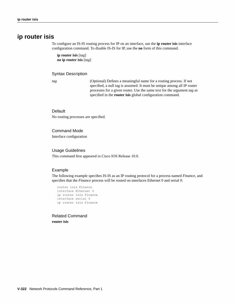
V-322 Network Protocols Command Reference, Part 1
ip router isis
ip router isisTo configure an IS-IS routing process for IP on an interface, use theip router isis interfaceconfiguration command. To disable IS-IS for IP, use theno form of this command.
ip router isis [tag]no ip router isis [tag]
Syntax Description
DefaultNo routing processes are specified.
Command ModeInterface configuration
Usage GuidelinesThis command first appeared in Cisco IOS Release 10.0.
ExampleThe following example specifies IS-IS as an IP routing protocol for a process namedFinance, andspecifies that theFinance process will be routed on interfaces Ethernet 0 and serial 0:
router isis Financeinterface Ethernet 0ip router isis Financeinterface serial 0ip router isis Finance
Related Commandrouter isis
tag (Optional) Defines a meaningful name for a routing process. If notspecified, a null tag is assumed. It must be unique among all IP routerprocesses for a given router. Use the same text for the argumenttag asspecified in therouter isis global configuration command.

ip rsvp bandwidth
IP Routing Protocols Commands V-323
ip rsvp bandwidthTo enable the use of the Resource Reservation Protocol (RSVP) protocol for IP on an interface, usetheip rsvp bandwidth interface configuration command. To disable this feature, use theno form ofthe command.
ip rsvp bandwidth [interface-kbps] [single-flow-kbps]no ip rsvp bandwidth [interface-kbps] [single-flow-kbps]
Syntax Description
DefaultDisabled
Command ModeInterface configuration
Usage GuidelinesThis command first appeared in Cisco IOS Release 11.2.
Use this command to enable the use of the RSVP for IP on an interface. The default is for RSVP tobe disabled to allow backward compatibility with systems that do not implement RSVP.
ExampleThe following example shows a T1 (1536 kbps) link configured to permit RSVP reservation of upto 1158 kbps, but no more than 100 kbps for any given flow on interfaces Ethernet 0 and serial 0.Fair queuing is configured with 15 reservable queues to support those reserved flows should they berequired.
interface Ethernet 0ip rsvp bandwidth 1158 100interface serial 0fair-queue 64 256 15
Related Commandsip rsvp udp-multicastip rsvp neighborsip rsvp senderip rsvp reservation
interface-kbps (Optional) Amount of bandwidth on interface to be reserved.
single-flow-kbps (Optional) Amount of bandwidth allocated to single flow.

V-324 Network Protocols Command Reference, Part 1
ip rsvp neighbors
ip rsvp neighborsTo enable neighbors to offer a reservation, use theip rsvp neighbors interface configurationcommand. To disable this feature, use theno form of the command.
ip rsvp neighborsaccess-list-number[no] ip rsvp neighborsaccess-list-number
Syntax Description
Command ModeInterface configuration
Usage GuidelinesThis command first appeared in IOS Release 11.2.
Use this command to allow RSVP neighbors to make a reservation. If no limits are specified, anyneighbor can offer a reservation. If an access list is specified, only neighbors meeting the specifiedaccess list requirements can make a reservation.
Related Commandsip rsvp bandwidthip rsvp udp-multicastip rsvp senderip rsvp reservation
access-list-number Number of a standard or extended access list. It can be aninteger from 1 to 199.

ip rsvp reservation
IP Routing Protocols Commands V-325
ip rsvp reservationTo enable a router to simulate Resource Reservation Protocol RSVP) RESV message reception fromthe sender, use theip rsvp reservationinterface configuration command. To disable this feature, usetheno form of the command.
ip rsvp reservationsession-ip-address sender-ip-address [UDP | TCP | ip-protocol]session-dport sender-sport next-hop-ip address nexthop-interface{ ff | se | wf} average kbpsburst-size { rate | load | delaynumber} [ bandwidth] [burst size]
no ip rsvp sendersession-ip-address sender-ip-address [UDP |TCP | ip-protocol] session-dportsender-sport next-hop-ip address nexthop-interface{ ff |se |wf} average kbps burst-size { rate |load | delaynumber} [ bandwidth] [burst-size]
Syntax Description
Command ModeInterface configuration
Usage GuidelinesThis command first appeared in Cisco IOS Release 11.2.
session-ip-address For unicast sessions, this is the address of the intended receiver;for multicast sessions, it is the IP multicast address of thesession.
sender-ip-address For unicast sessions, this is the address of the sender;for multicast sessions, it is the IP multicast address of thesession.
UDP | TCP | ip-protocol UDP or TCP session layer IP protocol.
session-dportsender-sport
Session-dport is the destination ports. Sender-sport is the sourceport. Port numbers are specified in all cases, as the use of 16-bitports following the IP header is not limited to UDP or TCP. Ifdestination is zero, source must be zero, and the implication isthat ports are not checked. If destination is non-zero, sourcemust be non-zero.
next-hop-ip-address Address of the receiver or the router closest to the receiver.
next-hop-interface Next hop interface or subinterface number.
ff | se | wf Reservation Style: Wild Card (wf), Shared Explicit (se), orFixed Filter (ff ).
rate | load | delaynumber QOS service: guaranteed rate, controlled load, or controlleddelay.
bandwidth Bit rate (kbps) to reserve up to 75 percent of total on interface.
burst-size Burst size (Kilobytes of data in queue).

V-326 Network Protocols Command Reference, Part 1
ip rsvp reservation
Use this command to force the router to act like it is receiving RSVP RESV messages from thesender.
ExamplesThe following example specifies the use of a Fixed Filter style of reservation and the ControlledDelay Service at Levels 1 or 2, and with token buckets of 100, 150, or 250 kbps and 60 or 65Kmaximum queue depth:
ip rsvp reservation 224.250.0.1 132.240.1.1 UDP 20 30 132.240.4.1 Et1 FF D 1 100 60ip rsvp reservation 224.250.0.1 132.240.2.1 UDP 20 30 132.240.4.1 Et1 FF D 1 150 65ip rsvp reservation 224.250.0.1 132.240.2.28 UDP 20 30 132.240.4.30 Et1 FF D 2 250 65
The following example specifies the use of a Fixed Filter style of reservation and the ControlledDelay Service at Levels 1 or 2, and with token buckets of 100, 150, or 250 kbps and 60 or 65Kmaximum queue depth:
ip rsvp reservation 224.250.0.1 132.240.1.1 UDP 20 30 132.240.4.1 Et1 FF D 1 100 60ip rsvp reservation 224.250.0.1 132.240.2.1 UDP 20 30 132.240.4.1 Et1 FF D 1 150 65ip rsvp reservation 224.250.0.1 132.240.2.28 UDP 20 30 132.240.4.30 Et1 FF D 2 250 65
The following example specifies the use of a Shared Explicit Filter style of reservation and theControlled Load Service, and with token buckets of 100 or 150 kbps and 60 or 65K maximum queuedepth:
ip rsvp reservation 224.250.0.2 132.240.1.1 UDP 20 30 132.240.4.1 Et1 SE LOAD 100 60ip rsvp reservation 224.250.0.2 132.240.2.1 TCP 20 30 132.240.4.1 Et1 SE LOAD 150 65
The following example specifies the use of a Wild Card Filter style of reservation and the Guaranteed BitRate Service, and with token buckets of 300 or 350 kbps and 60 or 65K maximum queue depth:
ip rsvp reservation 224.250.0.3 0.0.0.0 UDP 20 0 132.240.4.1 Et1 WF RATE 300 60ip rsvp reservation 224.250.0.3 0.0.0.0 UDP 20 0 132.240.4.1 Et1 WF RATE 350 65
Note that the Wild Card Filter does not admit the specification of the sender; it accepts all senders.This is denoted by setting the source address and port to zero. If, in any filter style, the destinationport is specified to be zero, RSVP does not permit the source port to be anything else; it understandsthat such protocols do not use ports or that the specification applies to all ports.
Related Commandsip rsvp bandwidthip rsvp udp-multicastip rsvp neighborsip rsvp sender

ip rsvp sender
IP Routing Protocols Commands V-327
ip rsvp senderTo enable a router to simulate Resource Reservation Protocol RSVP) PATH message reception fromthe sender, use theip rsvp senderinterface configuration command. To disable this feature, use theno form of the command.
ip rsvp sendersession-ip-address sender-ip-address [UDP | TCP | ip-protocol] session-dportsender-sport previous-hop-ip-address previous-hop-interface{ ff | se | wf} average kbpsburst-size { rate | load | delaynumber} [ bandwidth] [burst size]
no ip rsvp sendersession-ip-address sender-ip-address [UDP |TCP | ip-protocol] session-dportsender-sport previous-hop-ip-address previous-hop-interface{ ff | se | wf} average kbpsburst-size { rate | load | delaynumber} [ bandwidth] [burst size]
Syntax Description
Command ModeInterface configuration
session-ip-address For unicast sessions, this is the address of the intended receiver;for multicast sessions, it is the IP multicast address of thesession.
sender-ip-address For unicast sessions, this is the address of the sender;for multicast sessions, it is the IP multicast address of thesession.
UDP | TCP | ip-protocol UDP or TCP IP protocol.
session-dport sender-sport Destination/source ports. Port numbers are specified in allcases, as the use of 16-bit ports following the IP header is notlimited to UDP or TCP. If destination is zero, source must bezero, and the implication is that ports are not checked. Ifdestination is non-zero, source must be non-zero.
previous-hop-ip-address Address of the sender or the router closest to the sender.
previous-hop-interface Address of the previous hop interface or subinterface.
ff | se | wf Reservation Style: Wild Card (wf), Shared Explicit (se), orFixed Filter (ff ).
rate | load | delaynumber QOS service: guaranteed rate, controlled load, or controlleddelay.
bandwidth Bit rate (kbps) to reserve up to 75 percent of total on interface.
burst-size Burst size (kilobytes of data in queue).

V-328 Network Protocols Command Reference, Part 1
ip rsvp sender
Usage GuidelinesThis command first appeared in Cisco IOS Release 11.2.
Use this command to force the router to act like it is receiving RSVP PATH messages from thesender.
ExampleThe following example sets up the router to act like it receiving RSVP messages using UDP over theEth1 serial interface.
ip rsvp sender 224.250.0.1 132.240.2.1 UDP 20 30 132.240.2.1 Lo1 50 5ip rsvp sender 224.250.0.2 132.240.2.1 UDP 20 30 132.240.2.1 Lo1 50 5ip rsvp sender 224.250.0.2 132.240.2.28 UDP 20 30 132.240.2.28 Lo1 50 5
Related Commandsip rsvp bandwidthip rsvp neighborsip rsvp reservationip rsvp udp-multicast

ip rsvp udp-multicast
IP Routing Protocols Commands V-329
ip rsvp udp-multicastTo instruct the router to generate UDP-encapsulated Resource Reservation Protocol (RSVP)multicasts whenever it generates an IP multicast, use theip rsvp udp-multicast interfaceconfiguration command. To disable this feature, use theno form of the command.
ip rsvp udp-multicast [multicast-address]no ip rsvp udp-multicast [multicast-address]
Syntax Description
DefaultThe generation of UDP multicasts is not enabled. If a system sends a UDP-encapsulated RSVPmessage to the router, the router starts using UDP for contact with the neighboring system. Therouter uses multicast address 224.0.0.14 and starts sending to UDP port 1699. If the command isentered without specifying a multicast address, the router uses the same multicast address.
Command ModeInterface configuration
Usage GuidelinesThis command first appeared in Cisco IOS Release 11.2.
Use this command to instruct a router to generate UDP-encapsulated Resource Reservation Protocol(RSVP) multicasts whenever it generates an IP-encapsulated multicast packet. Some hosts requirethis trigger from the router.
ExampleThe following example reserves up to 7500 kbps on the Ethernet 2, with up to 1 Mbps per flow. Therouter is configured to use UDP encapsulation with the multicast address 224.0.0.14.
interface Ethernet 2ip rsvp bandwidth 7500 1000ip rsvp udp-multicast 224.0.0.14
Related Commandsip rsvp bandwidthip rsvp neighborsip rsvp senderip rsvp reservation
multicast-address (Optional) Multicast address of router.

V-330 Network Protocols Command Reference, Part 1
ip sd listen
ip sd listenTo enable the Cisco IOS software to listen to session directory advertisements, use theip sd listeninterface configuration command. To disable this feature, use theno form of this command.
ip sd listenno ip sd listen
Syntax DescriptionThis command has no arguments or keywords.
DefaultDisabled
Command ModeInterface configuration
Usage GuidelinesThis command first appeared in Cisco IOS Release 11.0.
Session Directory Protocol is a multicast application for creating desktop conferencing sessions. Itcreates group addresses and allows the user to specify the scope of the group and whether audio,video, or whiteboard applications will be invoked when others open the session.
Theip sd listen command merely enables the software to listen to session directory advertisements.The router joins the default session directory group (group 224.2.127.255) on the interface. Use thiscommand to get contact information.
ExampleThe following example enables a router to listen to session directory advertisements:
ip sd listen
Related Commandsclear ip sdshow ip sd

ip split-horizon
IP Routing Protocols Commands V-331
ip split-horizonTo enable the split horizon mechanism, use the ip split-horizon interface configuration command.To disable the split horizon mechanism, use theno form of this command.
ip split-horizonno ip split-horizon
Syntax DescriptionThis command has no arguments or keywords.
DefaultVaries with media
Command ModeInterface configuration
Usage GuidelinesThis command first appeared in Cisco IOS Release 10.0.
For all interfaces except those for which either Frame Relay or SMDS encapsulation is enabled, thedefault condition for this command isip split-horizon ; in other words, the split horizon feature isactive. If the interface configuration includes either theencapsulation frame-relay orencapsulation smds commands, then the default is for split horizon to be disabled. Split horizon isnot disabled by default for interfaces using any of the X.25 encapsulations.
Note For networks that include links over X.25 PSNs, theneighbor router configuration commandcan be used to defeat the split horizon feature. You can as an alternativeexplicitly specify theno ip split-horizon command in your configuration. However, if you do so youmust similarlydisable split horizon for all routers in any relevant multicast groups on that network.
If split horizon has been disabled on an interface and you wish to enable it, use theip split-horizoncommand to restore the split horizon mechanism.
Note In general, changing the state of the default for theip split-horizon command is notrecommended, unless you are certain that your application requires a change in order to properlyadvertise routes. If split horizon is disabled on a serial interface (and that interface is attached to apacket-switched network), youmust disable split horizon for all routers and access servers in anyrelevant multicast groups on that network.
ExampleThe following simple example disables split horizon on a serial link. The serial link is connected toan X.25 network:
interface serial 0

V-332 Network Protocols Command Reference, Part 1
ip split-horizon
encapsulation x25no ip split-horizon
Related Commandsip split-horizon eigrpneighbor

ip split-horizon eigrp
IP Routing Protocols Commands V-333
ip split-horizon eigrpTo enable Enhanced IGRP split horizon, use the ip split-horizon eigrp interface configurationcommand. To disable split horizon, use theno form of this command.
ip split-horizon eigrp autonomous-system-numberno ip split-horizon eigrp autonomous-system-number
Syntax Description
DefaultEnabled
Command ModeInterface configuration
Usage GuidelinesThis command first appeared in Cisco IOS Release 10.0.
For networks that include links over X.25 PSNs, you can use theneighbor router configurationcommand to defeat the split horizon feature. As an alternative, you can explicitly specify theno ip split-horizon eigrp command in your configuration. However, if you do so, you mustsimilarly disable split horizon for all routers and access servers in any relevant multicast groups onthat network.
In general, it is recommended that you not change the default state of split horizon unless you arecertain that your application requires the change in order to properly advertise routes. Rememberthat if split horizon is disabled on a serial interface and that interface is attached to a packet-switchednetwork, you must disable split horizon for all routers and access servers in any relevant multicastgroups on that network.
ExampleThe following example disables split horizon on a serial link connected to an X.25 network:
interface serial 0encapsulation x25no ip split-horizon eigrp
Related Commandsip split-horizonneighbor (EGP, IGRP, RIP)
autonomous-system-number Autonomous system number.

V-334 Network Protocols Command Reference, Part 1
ip summary-address eigrp
ip summary-address eigrpTo configure a summary aggregate address for a specified interface, use theip summary-addresseigrp interface configuration command. To disable a configuration, use theno form of thiscommand.
ip summary-address eigrpautonomous-system-number address maskno ip summary-address eigrpautonomous-system-number address mask
Syntax Description
DefaultNo summary aggregate addresses are predefined.
Command ModeInterface configuration
Usage GuidelinesThis command first appeared in Cisco IOS Release 10.0.
Enhanced IGRP summary routes are given an administrative distance value of 5. You cannotconfigure this value.
ExampleThe following example sets the IP summary aggregate address for Ethernet interface 0:
interface ethernet 0ip summary-address eigrp 109 192.1.0.0 255.255.0.0
Related Commandauto-summary
autonomous-system-number Autonomous system number.
address IP summary aggregate address to apply to an interface.
mask Subnet mask.

isis circuit-type
IP Routing Protocols Commands V-335
isis circuit-typeTo configure the type of adjacency, use theisis circuit-type interface configuration command. Toreset the circuit type to Level l and Level 2, use theno form of this command.
isis circuit-type { level-1 | level-1-2 | level-2-only}no isis circuit-type
Syntax Description
DefaultA Level 1 and Level 2 adjacency is established.
Command ModeInterface configuration
Usage GuidelinesThis command first appeared in Cisco IOS Release 10.0.
ExampleIn the following example, a router is configured to require Level 1 adjacency if there is at least onearea address in common between this system and its neighbors:
ip router isisinterface serial 0isis circuit-type level-1
level-1 A Level 1 adjacency may be established if there is at least onearea address in common between this system and its neighbors.
level-1-2 A Level 1 and Level 2 adjacency is established if the neighbor isalso configured aslevel-1-2 and there is at least one area incommon. If there is no area in common, a Level 2 adjacency isestablished. This is the default.
level-2-only A Level 2 adjacency is established if and only if the neighbor isconfigured exclusively to be a Level 2 router.

V-336 Network Protocols Command Reference, Part 1
isis csnp-interval
isis csnp-intervalTo configure the IS-IS complete sequence number PDUs (CSNP) interval, use the isis csnp-intervalinterface configuration command. To restore the default value, use theno form of this command.
isis csnp-intervalseconds { level-1 | level-2}no isis csnp-interval { level-1 | level-2}
Syntax Description
Default10 seconds
Command ModeInterface configuration
Usage GuidelinesThis command first appeared in Cisco IOS Release 10.0.
This command only applies for the designated router (DR) for a specified interface. Only DRs sendCSNP packets in order to maintain database synchronization. The CSNP interval can be configuredindependently for Level 1 and Level 2. This feature does not apply to serial point-to-point interfaces.It does apply to WAN connections if the WAN is viewed as a multiaccess meshed network.
ExampleIn the following example, serial interface 0 is configured for transmitting CSN PDUs every5 seconds. The router is configured to act as a station router.
interface serial 0isis csnp-interval 5 level-1
seconds Interval of time between transmission of CSNPs on multiaccessnetworks. This interval only applies for the designated router.The default is 10 seconds.
level-1 Configures the interval of time between transmission of CSNPsfor Level 1 independently.
level-2 Configures the interval of time between transmission of CSNPsfor Level 2 independently.

isis hello-interval
IP Routing Protocols Commands V-337
isis hello-intervalTo specify the length of time between hello packets that the Cisco IOS software sends, use theisishello-interval interface configuration command. To restore the default value, use theno form of thiscommand.
isis hello-interval seconds{ level-1 | level-2}no isis hello-interval{ level-1 | level-2}
Syntax Description
Default10 seconds
Command ModeInterface configuration
Usage GuidelinesThis command first appeared in Cisco IOS Release 10.0.
The hello interval can be configured independently for Level 1 and Level 2, except on serialpoint-to-point interfaces. (Because there is only a single type of hello packet sent on serial links, itis independent of Level 1 or Level 2.) The level-1 andlevel-2 keywords are used on X.25, SMDS,and Frame Relay multiaccess networks.
ExampleIn the following example, serial interface 0 is configured to advertise hello packets every 5 seconds.The router is configured to act as a station router. This will cause more traffic than configuring alonger interval, but topological changes will be detected faster.
interface serial 0isis hello-interval 5 level-1
seconds Unsigned integer value. A value three times the hello intervalsecondsis advertised as theholdtime in the hello packetstransmitted. It must be the same for all routers and accessservers attached to a common network. With smaller hellointervals, topological changes are detected faster, but there ismore routing traffic. The default is 10 seconds.
level-1 Configures the hello interval for Level 1 independently. Use thison X.25, SMDS, and Frame Relay multiaccess networks.
level-2 Configures the hello interval for Level 2 independently. Use thison X.25, SMDS, and Frame Relay multiaccess networks.

V-338 Network Protocols Command Reference, Part 1
isis metric
isis metricTo configure the metric for an interface, use the isis metric interface configuration command. Torestore the default metric value, use theno form of this command.
isis metric default-metric[delay-metric[expense-metric[error-metric]]] { level-1 | level-2}no isis metric{ level-1 | level-2}
Syntax Description
Defaultdefault-metric = 10
Command ModeInterface configuration
Usage GuidelinesThis command first appeared in Cisco IOS Release 10.0.
Specifying thelevel-1 or level-2 keywords resets the metric only for Level 1 or Level 2 routing,respectively.
ExampleIn the following example, serial interface 0 is configured for a default link-state metric cost of 15 forLevel 1:
interface serial 0isis metric 15 level-1
Related Commandsdefault-informationredistribute
default-metric Metric used for the redistributed route. The default metric isused as a value for the IS-IS metric. This is the value assignedwhen there is no QOS routing performed. Only this metric issupported by Cisco routers and access servers. You canconfigure this metric for Level 1 and/or Level 2 routing. Therange is from 0 to 63. The default value is 10.
delay-metric Not supported.
expense-metric Not supported.
error-metric Not supported.
level-1 Router acts as a station router (Level 1) only.
level-2 Router acts as an area router (Level 2) only.

isis password
IP Routing Protocols Commands V-339
isis passwordTo configure the authentication password for an interface, use theisis password interfaceconfiguration command. To disable authentication for IS-IS, use theno form of this command.
isis passwordpassword{ level-1 | level-2}no isis password { level-1 | level-2}
Syntax Description
DefaultDisabled
Command ModeInterface configuration
Usage GuidelinesThis command first appeared in Cisco IOS Release 10.0.
Different passwords can be assigned for different routing levels using thelevel-1 andlevel-2keyword arguments.
Specifying thelevel-1 or level-2 keywords disables the password only for Level 1 or Level 2 routing,respectively. If no keyword is specified, the default islevel-1.
ExampleThe following example configures a password for serial interface 0 at Level 1:
interface serial 0isis password frank level-1
password Authentication password you assign for an interface.
level-1 Configures the authentication password for Level 1independently. For Level 1 routing, the router acts as a stationrouter only.
level-2 Configures the authentication password for Level 2independently. For Level 2 routing, the router acts as an arearouter only.

V-340 Network Protocols Command Reference, Part 1
isis priority
isis priorityTo configure the priority of designated routers, use the isis priority interface configurationcommand. To reset the default priority, use theno form of this command.
isis priority value{ level-1 | level-2}no isis priority { level-1 | level-2}
Syntax Description
DefaultPriority of 64
Command ModeInterface configuration
Usage GuidelinesThis command first appeared in Cisco IOS Release 10.0.
Priorities can be configured for Level 1 and Level 2 independently. Specifying thelevel-1 orlevel-2 keywords resets priority only for Level 1 or Level 2 routing, respectively.
ExampleThe following example shows Level 1 routing given priority by setting the priority level to 50:
interface serial 0isis priority 50 level-1
value Sets the priority of a router and is a number from 0 to 127. Thedefault value is 64.
level-1 Sets the priority for Level 1 independently.
level-2 Sets the priority for Level 2 independently.

isis retransmit-interval
IP Routing Protocols Commands V-341
isis retransmit-intervalTo configure the time between retransmission of IS-IS link-state PDU (LSP) retransmission forpoint-to-point links, use theisis retransmit-interval interface configuration command. To restorethe default value, use theno form of this command.
isis retransmit-interval secondsno isis retransmit-interval seconds
Syntax Description
Default5 seconds
Command ModeInterface configuration
Usage GuidelinesThis command first appeared in Cisco IOS Release 10.0.
The setting of thesecondsargument should be conservative, or needless retransmission will result.The value should be larger for serial lines and virtual links.
ExampleThe following example configures serial interface 0 for retransmission of IS-IS LSP every10 seconds for a large serial line:
interface serial 0isis retransmit-interval 10
Related CommandsA dagger (†) indicates that the command is documented outside this chapter.
encapsulation ppp†
frame-relay keepalive†
smds dxi†
seconds Time in seconds between retransmission of IS-IS LSPretransmissions. It is an integer that should be greater than theexpected round-trip delay between any two routers on theattached network. The default is 5 seconds.

V-342 Network Protocols Command Reference, Part 1
is-type
is-typeTo configure the IS-IS level at which the Cisco IOS software operates, use theis-type routerconfiguration command. To reset the default value, use theno form of this command.
is-type { level-1 | level-1-2 | level-2-only}no is-type{ level-1 | level-1-2 | level-2-only}
Syntax Description
DefaultRouter acts as both a station router and an area router.
Command ModeRouter configuration
Usage Guidelines
This command first appeared in IOS Release 10.3.
ExampleThe following example specifies an area router:
router isisis-type level-2-only
level-1 Router acts as a station router.
level-1-2 Router acts as both a station router and an area router.
level-2-only Router acts as an area router only.

key
IP Routing Protocols Commands V-343
keyTo identify an authentication key on a key chain, use the key key chain configuration command. Toremove the key from the key chain, use theno form of this command.
key numberno keynumber
Syntax Description
DefaultNo key exists on the key chain.
Command ModeKey chain configuration
Usage GuidelinesThis command first appeared in Cisco IOS Release 11.1.
Currently, only RIP Version 2 uses authentication keys. It is useful to have multiple keys on a keychain so that the software can sequence through the keys as they become invalid after time, based ontheaccept-lifetime andsend-lifetime settings.
To remove all keys, remove the key chain by using theno key chain command.
If authentication is enabled, the software sends a RIP packet forevery active key on the key chain.Therefore, if two keys on the key chain happen to be active based on thesend-lifetime values, thesoftware sends two RIP packets every 30 seconds (one authenticated with each key).
ExampleThe following example configures a key chain calledtrees. In this example, the software will alwaysaccept and send willow as a valid key. The key chestnut will be accepted from 1:30 p.m. to 3:30 p.m.and be sent from 2:00 p.m. to 3:00 p.m. The overlap allows for migration of keys or a discrepancyin the router’s set time. Likewise, the key birch immediately follows chestnut, and there is a halfhourleeway on each side to handle time-of-day differences.
interface ethernet 0 ip rip authentication key-chain trees ip rip authentication mode md5!router rip network 172.19.0.0 version 2!key chain trees key 1 key-string willow
number Identification number of an authentication key on a key chain. The range ofkeys is 0 to 2147483647. The key identification numbers need not beconsecutive.

V-344 Network Protocols Command Reference, Part 1
key
key 2 key-string chestnut accept-lifetime 13:30:00 Jan 25 1996 duration 7200 send-lifetime 14:00:00 Jan 25 1996 duration 3600 key 3 key-string birch accept-lifetime 14:30:00 Jan 25 1996 duration 7200 send-lifetime 15:00:00 Jan 25 1996 duration 3600
Related Commandsaccept-lifetimekey chainkey-stringsend-lifetimeshow key chain
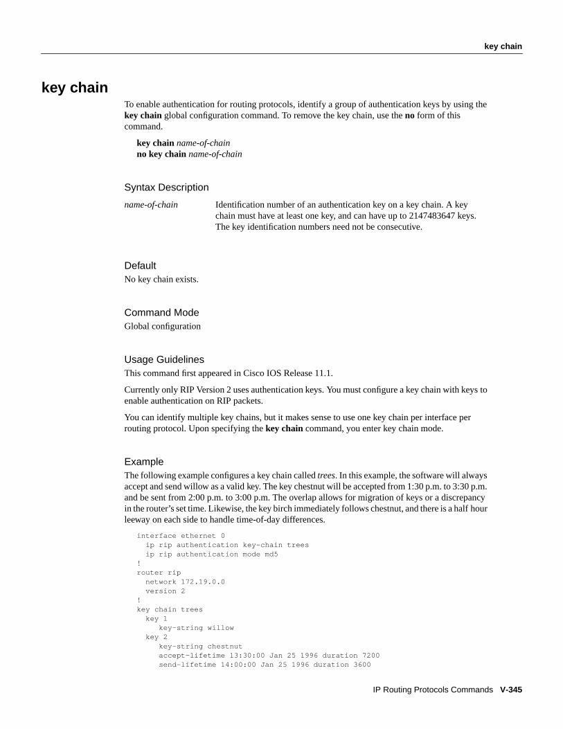
key chain
IP Routing Protocols Commands V-345
key chainTo enable authentication for routing protocols, identify a group of authentication keys by using thekey chainglobal configuration command. To remove the key chain, use theno form of thiscommand.
key chainname-of-chainno key chainname-of-chain
Syntax Description
DefaultNo key chain exists.
Command ModeGlobal configuration
Usage GuidelinesThis command first appeared in Cisco IOS Release 11.1.
Currently only RIP Version 2 uses authentication keys. You must configure a key chain with keys toenable authentication on RIP packets.
You can identify multiple key chains, but it makes sense to use one key chain per interface perrouting protocol. Upon specifying thekey chain command, you enter key chain mode.
ExampleThe following example configures a key chain calledtrees. In this example, the software will alwaysaccept and send willow as a valid key. The key chestnut will be accepted from 1:30 p.m. to 3:30 p.m.and be sent from 2:00 p.m. to 3:00 p.m. The overlap allows for migration of keys or a discrepancyin the router’s set time. Likewise, the key birch immediately follows chestnut, and there is a halfhourleeway on each side to handle time-of-day differences.
interface ethernet 0 ip rip authentication key-chain trees ip rip authentication mode md5!router rip network 172.19.0.0 version 2!key chain trees key 1 key-string willow key 2 key-string chestnut accept-lifetime 13:30:00 Jan 25 1996 duration 7200 send-lifetime 14:00:00 Jan 25 1996 duration 3600
name-of-chain Identification number of an authentication key on a key chain. A keychain must have at least one key, and can have up to 2147483647 keys.The key identification numbers need not be consecutive.

V-346 Network Protocols Command Reference, Part 1
key chain
key 3 key-string birch accept-lifetime 14:30:00 Jan 25 1996 duration 7200 send-lifetime 15:00:00 Jan 25 1996 duration 3600
Related Commandsaccept-lifetimeip rip authentication key-chainkeykey-stringsend-lifetimeshow key chain

key-string
IP Routing Protocols Commands V-347
key-stringTo specify the authentication string for a key, use the key-string key chain key configurationcommand. To remove the authentication string, use theno form of this command.
key-string textno key-string [text]
Syntax Description
DefaultNo key exists.
Command ModeKey chain key configuration
Usage GuidelinesThis command first appeared in Cisco IOS Release 11.1.
Currently only RIP Version 2 uses authentication keys. Each key can have only one key string.
If password encryption is configured (with theservice password-encryptioncommand), thesoftware saves the key string as encrypted text. When you write to the terminal with theshow running-config command, the software displayskey-string 7 encrypted text .
ExampleThe following example configures a key chain calledtrees. In this example, the software will alwaysaccept and send willow as a valid key. The key chestnut will be accepted from 1:30 p.m. to 3:30 p.m.and be sent from 2:00 p.m. to 3:00 p.m. The overlap allows for migration of keys or a discrepancyin the router’s set time. Likewise, the key birch immediately follows chestnut, and there is a halfhourleeway on each side to handle time-of-day differences.
interface ethernet 0 ip rip authentication key-chain trees ip rip authentication mode md5!router rip network 172.19.0.0 version 2!key chain trees key 1 key-string willow key 2 key-string chestnut accept-lifetime 13:30:00 Jan 25 1996 duration 7200 send-lifetime 14:00:00 Jan 25 1996 duration 3600
text Authentication string that must be sent and received in the packets using the routingprotocol being authenticated. The string can contain from 1 to 80 uppercase andlowercase alphanumeric characters, except that the first character cannot be a number.

V-348 Network Protocols Command Reference, Part 1
key-string
key 3 key-string birch accept-lifetime 14:30:00 Jan 25 1996 duration 7200 send-lifetime 15:00:00 Jan 25 1996 duration 3600
Related CommandsA dagger (†) indicates that the command is documented outside this chapter.
accept-lifetimekeykey chainsend-lifetimeservice password-encryption†
show key chain

log-neighbor-changes
IP Routing Protocols Commands V-349
log-neighbor-changesTo enable the logging of changes in enhanced IGRP neighbor adjacencies, use thelog-neighbor-change router configuration command. To disable the logging of changes in enhancedIGRP neighbor adjacencies, use theno form of this command.
log-neighbor-changesno log-neighbor-changes
Syntax DescriptionThis command has not arguments or keywords.
DefaultNo adjacency changes are logged.
Command ModeRouter configuration
Usage GuidelinesThis command first appeared in Cisco IOS Release 11.2.
Enables the logging of neighbor adjacency changes to monitor the stability of the routing system andto help detect problems.
ExampleThe following configuration will log neighbor changes for enhanced IGRP process 209:
ip router eigrp 209log-neighbor-changes

V-350 Network Protocols Command Reference, Part 1
match as-path
match as-pathTo match a BGP autonomous system path access list, use thematch as-path route-mapconfiguration command. To remove a path list entry, theno form of this command.
match as-pathpath-list-numberno match as-pathpath-list-number
Syntax Description
DefaultNo path lists are defined.
Command ModeRoute-map configuration
Usage GuidelinesThis command first appeared in Cisco IOS Release 10.0.
The values set by thematch andset commands override global values. For example, the weightsassigned with thematch as-path and set weight route-map commands override the weightsassigned using the neighbor weight andneighbor filter-list commands.
A route map can have several parts. Any route that does not match at least onematch clause relatingto aroute-map command will be ignored; that is, the route will not be advertised for outbound routemaps and will not be accepted for inbound route maps. If you want to modify only some data, youmust configure a second route-map section with an explicit match specified.
The implemented weight is based on the first matched autonomous system path.
ExampleIn the following example, the autonomous system path is set to match BGP autonomous system pathaccess list 20:
route-map igp2bgpmatch as-path 20
Related Commandsmatch community-listmatch interfacematch ip addressmatch ip next-hopmatch ip route-sourcematch metricmatch route-typematch tagroute-mapset as-path
path-list-number Autonomous system path access list. An integer from 1 to 199.

match as-path
IP Routing Protocols Commands V-351
set automatic-tagset communityset levelset local-preferenceset metricset metric-typeset next-hopset originset tagset weight

V-352 Network Protocols Command Reference, Part 1
match community-list
match community-listTo match a BGP community, use thematch community-list route-map configuration command. Toremove the community list entry, use theno form of this command.
match community-list community-list-number [exact]no match community-listcommunity-list-number [exact]
Syntax Description
DefaultNo community list is defined.
Command ModeRoute-map configuration
Usage GuidelinesThis command first appeared in Cisco IOS Release 10.3.
A route map can have several parts. Any route that does not match at least onematch clause relatingto aroute-map command will be ignored; that is, the route will not be advertised for outbound routemaps and will not be accepted for inbound route maps. If you want to modify only some data, youmust configure a second route-map section with an explicit match specified.
Matching based on community list is one of the types of match clauses applicable to BGP.
ExamplesIn the following example, the routes that match community list 1 will have the weight set to 100.Any route that has community 109 will have the weight set to 100.
ip community-list 1 permit 109!route-map set_weightmatch community-list 1set weight 100
In the following example, the routes that match community list 1 will have the weight set to 200.Any route that has community 109 alone will have the weight set to 200.
ip community-list 1 permit 109!route-map set_weightmatch community-list 1 exactset weight 200
community-list-number Community list number in the range 1 to 99.
exact (Optional) Indicates an exact match is required. All of thecommunities and only those communities in the community listmust be present.

match community-list
IP Routing Protocols Commands V-353
Related Commandsip cgmproute-mapset weight

V-354 Network Protocols Command Reference, Part 1
match interface
match interfaceTo distribute any routes that have their next hop out one of the interfaces specified, use thematchinterface route-map configuration command. To remove thematch interface entry, use theno formof this command.
match interface type number...type numberno match interfacetype number...type number
Syntax Description
DefaultNo match interfaces are defined.
Command ModeRoute-map configuration
Usage GuidelinesThis command first appeared in Cisco IOS Release 10.0.
Use the route-map global configuration command, and thematch andset route-map configurationcommands, to define the conditions for redistributing routes from one routing protocol into another.Eachroute-map command has a list ofmatch andset commands associated with it. Thematchcommands specify thematch criteria—the conditions under which redistribution is allowed for thecurrentroute-map command. Theset commands specify theset actions—the particularredistribution actions to perform if the criteria enforced by thematch commands are met. Thenoroute-map command deletes the route map.
Thematch route-map configuration command has multiple formats. Thematch commands may begiven in any order, and allmatch commands must “pass” to cause the route to be redistributedaccording to theset actionsgiven with theset commands. Theno forms of thematch commandsremove the specified match criteria.
A route map can have several parts. Any route that does not match at least onematch clause relatingto aroute-map command will be ignored; that is, the route will not be advertised for outbound routemaps and will not be accepted for inbound route maps. If you want to modify only some data, youmust configure a second route-map section with an explicit match specified.
ExampleIn the following example, routes that have their next hop out Ethernet interface 0 will be distributed:
route-map namematch interface ethernet 0
type Interface type.
number Interface number.

match interface
IP Routing Protocols Commands V-355
Related Commandsmatch as-pathmatch community-listmatch ip addressmatch ip next-hopmatch ip route-sourcematch metricmatch route-typematch tagroute-mapset as-pathset automatic-tagset communityset levelset local-preferenceset metricset metric-typeset next-hopset originset tagset weight

V-356 Network Protocols Command Reference, Part 1
match ip address
match ip addressTo distribute any routes that have a destination network number address that is permitted by astandard or extended access list, or to perform policy routing on packets, use thematch ip addressroute-map configuration command. To remove thematch ip address entry, use theno form of thiscommand.
match ip addressaccess-list-number| name...access-list-number | nameno match ip addressaccess-list-number| name...access-list-number | name
Syntax Description
DefaultNo access list numbers are specified.
Command ModeRoute-map configuration
Usage GuidelinesThis command first appeared in Cisco IOS Release 10.0.
Use route maps to redistribute routes or to subject packets to policy routing. Both purposes aredescribed in this section.
• Redistribution
Use the route-map global configuration command, and thematch andset route-mapconfiguration commands, to define the conditions for redistributing routes from one routingprotocol into another. Eachroute-map command has a list ofmatch andset commandsassociated with it. Thematch commands specify thematch criteria—the conditions under whichredistribution is allowed for the currentroute-map. Theset commands specify thesetactions—the particular redistribution actions to perform if the criteria enforced by thematchcommands are met. Theno route-mapcommand deletes the route map.
Thematch route-map configuration command has multiple formats. The relatedmatchcommands are listed in the section “Related Commands for Redistribution.” Thematchcommands can be given in any order, and allmatch commands must “pass” to cause the route tobe redistributed according to theset actionsgiven with theset commands. Theno forms of thematch commands remove the specified match criteria.
When you are passing routes through a route map, a route map can have several parts. Any routethat does not match at least onematch clause relating to aroute-map command will be ignored;that is, the route will not be advertised for outbound route maps and will not be accepted forinbound route maps. If you want to modify only some data, you must configure a secondroute-map section with an explicit match specified.
• Policy Routing
access-list-number| name Number or name of a standard or extended access list. It can bean integer from 1 to 199.

match ip address
IP Routing Protocols Commands V-357
Another purpose of route maps is to enable policy routing. Use the ip policy route-mapinterfaceconfiguration command, in addition to theroute-map global configuration command, and thematch and set route-map configuration commands to define the conditions for policy routingpackets. Eachroute-map command has a list ofmatch andset commands associated with it. Therelatedmatch andset commands are listed in the section “Related Commands for PolicyRouting.” Thematch commands specify thematch criteria—the conditions under which policyrouting occurs. Theset commands specify theset actions—the particular routing actions toperform if the criteria enforced by thematch commands are met. You might want to policy routepackets based on their source, for example, using an access list.
ExamplesIn the following example, routes that have addresses specified by access list numbers 5or 80 will bematched:
route-map namematch ip address 5 80
In the following policy routing example, packets that have addresses specified by access list numbers6 or 25 will be routed to Ethernet interface 0:
interface serial 0ip policy route-map chicago!route-map chicagomatch ip address 6 25set interface ethernet 0
Related Commands for Redistributionmatch as-pathmatch community-listmatch interfacematch ip next-hopmatch ip route-sourcematch metricmatch route-typematch tagroute-mapset as-pathset automatic-tagset communityset levelset local-preferenceset metricset metric-typeset next-hopset originset tagset weight

V-358 Network Protocols Command Reference, Part 1
match ip address
Related Commands for Policy Routingip policy route-mapmatch lengthroute-mapset default interfaceset interfaceset ip default next-hopset ip next-hop

match ip next-hop
IP Routing Protocols Commands V-359
match ip next-hopTo redistribute any routes that have a next-hop router address passed by one of the access listsspecified, use thematch ip next-hop route-map configuration command. To remove the next-hopentry, use theno form of this command.
match ip next-hop {access-list-number| name}[ ...access-list-number| name]no match ip next-hop{ access-list-number| name}[ ...access-list-number| name]
Syntax Description
DefaultRoutes are distributed freely, without being required to match a next-hop address.
Command ModeRoute-map configuration
Usage GuidelinesThis command first appeared in Cisco IOS Release 10.0.
Use the route-map global configuration command, and thematch andsetroute-map configurationcommands, to define the conditions for redistributing routes from one routing protocol into another.Eachroute-map command has a list ofmatch andset commands associated with it. Thematchcommands specify thematch criteria—the conditions under which redistribution is allowed for thecurrentroute-map command. Theset commands specify theset actions—the particularredistribution actions to perform if the criteria enforced by thematch commands are met. Thenoroute-map command deletes the route map.
Thematch route-map configuration command has multiple formats. Thematch commands may begiven in any order, and allmatch commands must “pass” to cause the route to be redistributedaccording to theset actionsgiven with theset commands. Theno forms of thematch commandsremove the specified match criteria.
A route map can have several parts. Any route that does not match at least onematch clause relatingto aroute-map command will be ignored; that is, the route will not be advertised for outbound routemaps and will not be accepted for inbound route maps. If you want to modify only some data, youmust configure a second route-map section with an explicit match specified.
ExampleIn the following example, routes that have a next-hop router address passed by access list 5 or 80will be distributed:
route-map namematch ip next-hop 5 80
access-list-number| name Number or name of a standard or extended access list. It can bean integer from 1 to 199.

V-360 Network Protocols Command Reference, Part 1
match ip next-hop
Related Commandsmatch as-pathmatch community-listmatch interfacematch ip addressmatch ip route-sourcematch metricmatch route-typematch tagroute-mapset as-pathset automatic-tagset communityset levelset local-preferenceset metricset metric-typeset next-hopset originset tagset weight

match ip route-source
IP Routing Protocols Commands V-361
match ip route-sourceTo redistribute routes that have been advertised by routers and access servers at the address specifiedby the access lists, use thematch ip route-source route-map configuration command. To removethe route-source entry, use theno form of this command.
match ip route-source {access-list-number| name}[ ...access-list-number| name]no match ip route-source {access-list-number| name}[ ...access-list-number| name]
Syntax Description
DefaultNo filtering on route source.
Command ModeRoute-map configuration
Usage GuidelinesThis command first appeared in Cisco IOS Release 10.0.
Use the route-map global configuration command, and thematch andset route-map configurationcommands, to define the conditions for redistributing routes from one routing protocol into another.Eachroute-map command has a list ofmatch andset commands associated with it. Thematchcommands specify thematch criteria— the conditions under which redistribution is allowed for thecurrentroute-map. Theset commands specify theset actions—the particular redistribution actionsto perform if the criteria enforced by thematch commands are met. Theno route-mapcommanddeletes the route map.
Thematch route-map configuration command has multiple formats. Thematch commands may begiven in any order, and allmatch commands must “pass” to cause the route to be redistributedaccording to theset actionsgiven with theset commands. Theno forms of thematch commandsremove the specified match criteria.
A route map can have several parts. Any route that does not match at least onematch clause relatingto aroute-map command will be ignored; that is, the route will not be advertised for outbound routemaps and will not be accepted for inbound route maps. If you want to modify only some data, youmust configure second route-map section with an explicit match specified.
There are situations in which a route’s next hop and source router address are not the same.
ExampleIn the following example, routes that have been advertised by routers and access servers at theaddresses specified by access lists 5 and 80 will be distributed:
route-map namematch ip route-source 5 80
access-list-number| name Number or name of a standard or extended access list. It can bean integer from 1 to 199.

V-362 Network Protocols Command Reference, Part 1
match ip route-source
Related Commandsmatch as-pathmatch community-listmatch interfacematch ip addressmatch ip next-hopmatch metricmatch route-typematch tagroute-mapset as-pathset automatic-tagset communityset levelset local-preferenceset metricset metric-typeset next-hopset originset tagset weight

match length
IP Routing Protocols Commands V-363
match lengthTo base policy routing on the Level 3 length of a packet, use thematch length route-mapconfiguration command. To remove the entry, use theno form of this command.
match lengthmin maxno match lengthmin max
Syntax Description
DefaultNo policy routing on the length of a packet.
Command ModeRoute-map configuration
Usage GuidelinesThis command first appeared in Cisco IOS Release 11.0.
Use the ip policy route-mapinterface configuration command, theroute-map global configurationcommand, and thematch andset route-map configuration commands, to define the conditions forpolicy routing packets. Theip policy route-map command identifies a route map by name. Eachroute-map has a list ofmatch andset commands associated with it. Thematch commands specifythematch criteria—the conditions under which policy routing occurs. Theset commands specifytheset actions—the particular routing actions to perform if the criteria enforced by thematchcommands are met.
Thematch route-map configuration command has multiple formats. Thematch commands can begiven in any order, and allmatch commands must “pass” to cause the packet to be routed accordingto theset actionsgiven with theset commands. Theno forms of thematch commands remove thespecified match criteria.
You might want to base your policy routing on the length of packets so that your interactive trafficand bulk traffic are directed to different routers.
ExampleIn the following example, packets 3 to 200 bytes long, inclusive, will be routed to FDDI interface 0:
interface serial 0ip policy route-map interactive!route-map interactivematch length 3 200set interface fddi 0
min Minimum Level 3 length of the packet, inclusive, allowed for a match.Range is 0 to 0x7FFFFFFF.
max Maximum Level 3 length of the packet, inclusive, allowed for a match.Range is 0 to 0x7FFFFFFF.

V-364 Network Protocols Command Reference, Part 1
match length
Related Commandsip policy route-mapmatch ip addressroute-mapset default interfaceset interfaceset ip default next-hopset ip next-hop

match metric
IP Routing Protocols Commands V-365
match metricTo redistribute routes with the metric specified, use thematch metric route-map configurationcommand. To remove the entry, use theno form of this command.
match metric metric-valueno match metricmetric-value
Syntax Description
DefaultNo filtering on a metric value.
Command ModeRoute-map configuration
Usage GuidelinesThis command first appeared in Cisco IOS Release 11.2.
Use the route-map global configuration command, and thematch andset route-map configurationcommands, to define the conditions for redistributing routes from one routing protocol into another.Eachroute-map command has a list ofmatch andset commands associated with it. Thematchcommands specify thematch criteria—the conditions under which redistribution is allowed for thecurrentroute-map command. Theset commands specify theset actions—the particularredistribution actions to perform if the criteria enforced by thematch commands are met. Thenoroute-map command deletes the route map.
Thematch route-map configuration command has multiple formats. Thematch commands may begiven in any order, and allmatch commands must “pass” to cause the route to be redistributedaccording to theset actionsgiven with theset commands. Theno forms of thematch commandsremove the specified match criteria.
A route map can have several parts. Any route that does not match at least onematch clause relatingto aroute-mapcommand will be ignored; that is, the route will not be advertised for outbound routemaps and will not be accepted for inbound route maps. If you want to modify only some data, youmust configure second route-map section with an explicit match specified.
ExampleIn the following example, routes with the metric 5 will be redistributed:
route-map namematch metric 5
metric-value Route metric, which can be an IGRP five-part metric. It is ametric value from 0 to 4294967295.

V-366 Network Protocols Command Reference, Part 1
match metric
Related Commandsmatch as-pathmatch community-listmatch interfacematch ip addressmatch ip next-hopmatch ip route-sourcematch route-typematch tagroute-mapset as-pathset automatic-tagset communityset levelset local-preferenceset metricset metric-typeset next-hopset originset tagset weight

match route-type
IP Routing Protocols Commands V-367
match route-typeTo redistribute routes of the specified type, use thematch route-type route-map configurationcommand. To remove the route-type entry, use theno form of this command.
match route-type { local | internal | external [type-1 | type-2] | level-1 | level-2}no match route-type { local | internal | external [type-1 | type-2] | level-1 | level-2}
Syntax Description
DefaultDisabled
Command ModeRoute-map configuration
Usage GuidelinesThis command first appeared in Cisco IOS Release 10.0. The following keywords first appeared inCisco IOS Release 11.2:local andexternal [type-1 | type-2].
Use the route-map global configuration command, and thematch andset route-map configurationcommands, to define the conditions for redistributing routes from one routing protocol into another.Eachroute-map command has a list ofmatch andset commands associated with it. Thematchcommands specify thematch criteria—the conditions under which redistribution is allowed for thecurrentroute-map command. Theset commands specify theset actions—the particularredistribution actions to perform if the criteria enforced by thematch commands are met. Thenoroute-map command deletes the route map.
Thematch route-map configuration command has multiple formats. Thematch commands may begiven in any order, and allmatch commands must “pass” to cause the route to be redistributedaccording to theset actionsgiven with theset commands. Theno forms of thematch commandsremove the specified match criteria.
A route map can have several parts. Any route that does not match at least onematch clause relatingto aroute-map command will be ignored; that is, the route will not be advertised for outbound routemaps and will not be accepted for inbound route maps. If you want to modify only some data, youmust configure second route-map section with an explicit match specified.
local Locally generated BGP routes.
internal OSPF intra-area and interarea routes or enhanced IGRP internalroutes.
external [type-1 | type-2] OSPF external routes, or enhanced IGRP external routes. ForOSPF,external type-1 matches only Type 1 external routes andexternal type-2 matches only Type 2 external routes.
level-1 IS-IS Level 1 routes.
level-2 IS-IS Level 2 routes.
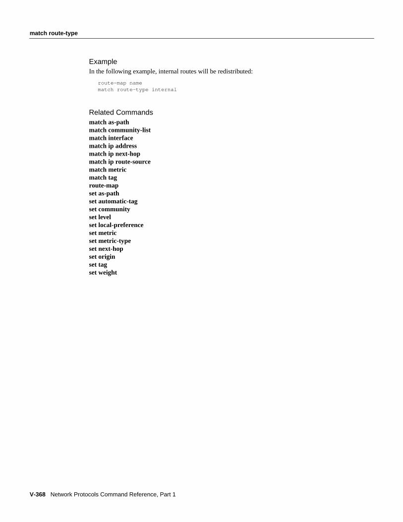
V-368 Network Protocols Command Reference, Part 1
match route-type
ExampleIn the following example, internal routes will be redistributed:
route-map namematch route-type internal
Related Commandsmatch as-pathmatch community-listmatch interfacematch ip addressmatch ip next-hopmatch ip route-sourcematch metricmatch tagroute-mapset as-pathset automatic-tagset communityset levelset local-preferenceset metricset metric-typeset next-hopset originset tagset weight

match tag
IP Routing Protocols Commands V-369
match tagTo redistribute routes in the routing table that match the specified tags, use thematch tagroute-mapconfiguration command. To remove the tag entry, use theno form of this command.
match tag tag-value...tag-valueno match tagtag-value...tag-value
Syntax Description
DefaultNo match tag values are defined.
Command ModeRoute-map configuration
Usage GuidelinesThis command first appeared in Cisco IOS Release 10.0.
Use the route-map global configuration command, and thematch andsetroute-map configurationcommands, to define the conditions for redistributing routes from one routing protocol into another.Eachroute-map command has a list ofmatch andset commands associated with it. Thematchcommands specify thematch criteria—the conditions under which redistribution is allowed for thecurrentroute-map command. Theset commands specify theset actions—the particularredistribution actions to perform if the criteria enforced by thematch commands are met. Thenoroute-map command deletes the route map.
Thematch route-map configuration command has multiple formats. Thematch commands may begiven in any order, and allmatch commands must “pass” to cause the route to be redistributedaccording to theset actionsgiven with theset commands. Theno forms of thematch commandsremove the specified match criteria.
A route map can have several parts. Any route that does not match at least onematch clause relatingto aroute-map command will be ignored; that is, the route will not be advertised for outbound routemaps and will not be accepted for inbound route maps. If you want to modify only some data, youmust configure second route-map section with an explicit match specified.
ExampleIn the following example, routes stored in the routing table with tag 5 will be redistributed:
route-map namematch tag 5
tag-value List of one or more route tag values. Each can be an integerfrom 0 to 4294967295.

V-370 Network Protocols Command Reference, Part 1
match tag
Related Commandsmatch as-pathmatch community-listmatch interfacematch ip addressmatch ip next-hopmatch ip route-sourcematch metricmatch route-typeroute-mapset as-pathset automatic-tagset communityset levelset local-preferenceset metricset metric-typeset next-hopset originset tagset weight

maximum-paths
IP Routing Protocols Commands V-371
maximum-pathsTo control the maximum number of parallel routes an IP routing protocol can support, use themaximum-pathsrouter configuration command. To restore the default value, use theno form of thiscommand.
maximum-pathsmaximumno maximum-paths
Syntax Description
DefaultsThe default for BGP is 1 path. The default for all other IP routing protocols is 4 paths.
Command ModeRouter configuration
Usage GuidelinesThis command first appeared in Cisco IOS Release 11.2.
ExampleThe following example allows a maximum of 2 paths to a destination:
maximum-paths 2
maximum Maximum number of parallel routes an IP routing protocol installs in arouting table, in the range 1 to 6.

V-372 Network Protocols Command Reference, Part 1
mbranch
mbranchTo trace a branch of a multicast tree for a specific group, use thembranch EXEC command.
mbranch { group-address | group-name} branch[ttl]
Syntax Description
Command ModeEXEC
Usage GuidelinesThis command first appeared in Cisco IOS Release 10.0.
Thembranch command sends multicast IGMP trace request packets to the specified branch router.It displays information about the branch starting with the local (requesting) router and ending withthe branch router. This is considered to be the forward direction.
The information returned shows how a multicast packet sourced by this router will be forwarded byeach router on the path to the router with the branch address.
The router with the addressbranch-address is the only router that responds to the trace requestpackets. The response is unicast to the source.
It is important to specify a value for thettl argument if you are tracing through a router on which amulticast threshold has been set with theip multicast ttl-threshold interface configurationcommand.
Sample DisplayThe following is sample output from thembranch command. This trace is between the same routersas shown in the example for thembranch command. Note the order of responses. Also note that theoutgoing interface list is the same.
PIM2# mbranch 224.0.255.2 198.92.118.2
Type escape sequence to abort.Tracing route to group CBONE-WB (224.0.255.2) to 198.92.118.2
group-address Address of the multicast group. This is a multicast IP address infour-part, dotted notation.
group-name Name of the multicast group, as defined in the DNS hosts table or withthe ip host command.
branch Address or name of a router that is on the tree branch. The address is aunicast IP address in four-part, dotted notation.
ttl (Optional) Time-to-live value, in hops, that is used in trace requestpackets sent to the branch router. The default value is 30.
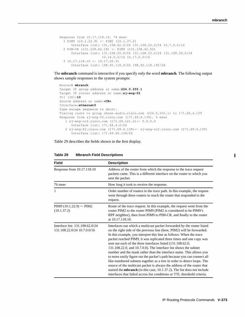
mbranch
IP Routing Protocols Commands V-373
Response from 10.17.118.10, 76 msec 1 PIM9 (10.1.22.9) <- PIM2 (10.1.37.2) Interface list: 131.108.62.0/24 131.108.22.0/24 10.7.0.0/16 2 PIM-CR (131.108.62.18) <- PIM9 (131.108.62.52) Interface list: 131.108.20.0/24 131.108.53.0/24 131.108.50.0/24 10.16.0.0/16 10.17.0.0/16 3 10.17.118.10 <- 10.17.20.31 Interface list: 198.92.118.0/26 198.92.118.192/26
Thembranch command is interactive if you specify only the wordmbranch. The following outputshows sample responses to the system prompts:
Router# mbranchTarget IP group address or name: 224.0.255.1Target IP router address or name: sj-eng-f2Ttl [30]: 10Source address or name: <CR>Interface: ethernet0Type escape sequence to abort.Tracing route to group cbone-audio.cisco.com (224.0.255.1) to 171.69.4.139Response from sj-eng-f2.cisco.com (171.69.4.139), 4 msec
1 sj-eng-cc2.cisco.com (171.69.121.2)<- 0.0.0.0Interface list: 171.69.4.0/24
2 sj-eng-f2.cisco.com (171.69.4.139)<- sj-eng-cc2.cisco.com (171.69.4.135)Interface list: 171.69.60.128/26
Table 29 describes the fields shown in the first display.
Table 29 Mbranch Field Descriptions
Field Description
Response from 10.17.118.10 Address of the router from which the response to the trace requestpackets came. This is a different interface on the router to which yousent the packet.
76 msec How long it took to receive the response.
1 Order number of routers in the trace path. In this example, the requestwent through three routers to reach the router that responded to therequest.
PIM9 (10.1.22.9) <- PIM2(10.1.37.2)
Route of the trace request. In this example, the request went from therouter PIM2 to the router PIM9 (PIM2 is considered to be PIM9’sRPF neighbor), then from PIM9 to PIM-CR, and finally to the routerat 10.17.118.10.
Interface list: 131.108.62.0/24131.108.22.0/24 10.7.0.0/16
Interfaces out which a multicast packet forwarded by the router listedon the right side of the previous line (here, PIM2) will be forwarded.In this example, you interpret this line as follows: When the tracepacket reached PIM9, it was replicated three times and one copy wassent out each of the three interfaces listed (131.108.62.0,131.108.22.0, and 10.7.0.0). The interface list shows the subnetnumber and the mask rather than the interface name. This allows youto more easily figure out the packet’s path because you can connect alllike-numbered subnets together as a tree in order to detect loops. Thesource of the multicast packet is always the address of the router thatstarted thembranch (in this case, 10.1.37.2). The list does not includeinterfaces that failed access list conditions or TTL threshold criteria.

V-374 Network Protocols Command Reference, Part 1
mbranch
Related Commandsip multicast ttl-thresholdmrbranch

metric holddown
IP Routing Protocols Commands V-375
metric holddownTo keep new IGRP routing information from being used for a certain period of time, use the metricholddown router configuration command. To disable this feature, use theno form of this command.
metric holddownno metric holddown
Syntax DescriptionThis command has no arguments or keywords.
DefaultDisabled
Command ModeRouter configuration
Usage GuidelinesThis command first appeared in Cisco IOS Release 10.0.
Holddown keeps new routing information from being used for a certain period of time. This canprevent routing loops caused by slow convergence. It is sometimes advantageous to disableholddown to increase the network’s ability to quickly respond to topology changes; this commandprovides this function.
Use themetric holddown command if other routers or access servers within the IGRP autonomoussystem are not configured withno metric holddown. If all routers are not configured the same way,you increase the possibility of routing loops.
ExampleThe following example disables metric holddown:
router igrp 15network 131.108.0.0network 192.31.7.0no metric holddown
Related Commandsmetric maximum-hopsmetric weightstimers basic (EGP, RIP, IGRP)

V-376 Network Protocols Command Reference, Part 1
metric maximum-hops
metric maximum-hopsTo have the IP routing software to advertise as unreachable those routes with a hop count higher thanis specified by the command (IGRP only), use the metric maximum-hops router configurationcommand. To reset the value to the default, use theno form of this command.
metric maximum-hopshopsno metric maximum-hopshops
Syntax Description
Default100 hops
Command ModeRouter configuration
Usage GuidelinesThis command first appeared in Cisco IOS Release 10.0.
This command provides a safety mechanism that breaks any potentialcount-to-infinity problems. Itcauses the IP routing software to advertise as unreachable routes with a hop count greater than thevalue assigned to thehops argument.
ExampleIn the following example, a router in autonomous system 71 attached to network 15.0.0.0 wants amaximum hop count of 200, doubling the default. The network administrators decided to do thisbecause they have a complex WAN that can generate a large hop count under normal (nonlooping)operations.
router igrp 71network 15.0.0.0metric maximum-hops 200
Related Commandsmetric holddownmetric weights
hops Maximum hop count (in decimal). The default value is 100hops; the maximum number of hops that can be specified is255.

metric weights
IP Routing Protocols Commands V-377
metric weightsTo allow the tuning of the IGRP or Enhanced IGRP metric calculations, use the metric weightsrouter configuration command. To reset the values to their defaults, use theno form of thiscommand.
metric weights tos k1 k2 k3 k4 k5no metric weights
Syntax Description
Defaultstos: 0k1: 1k2: 0k3: 1k4: 0k5: 0
Command ModeRouter configuration
Usage GuidelinesThis command first appeared in Cisco IOS Release 10.0.
Use this command to alter the default behavior of IGRP routing and metric computation and allowthe tuning of the IGRP metric calculation for a particular type of service (TOS).
If k5 equals 0, the composite IGRP or enhanced IGRP metric is computed according to the followingformula:
metric = [k1 * bandwidth + (k2 * bandwidth)/(256 - load) + k3 * delay]
If k5 does not equal zero, an additional operation is done:
metric = metric * [k5 / (reliability + k4)]
Bandwidth is inverse minimum bandwidth of the path in bits per second scaled by a factor of2.56× 1012. The range is from a 1200-bps line to 10 terabits per second.
Delay is in units of 10 microseconds. This gives a range of 10 microseconds to 168 seconds. A delayof all ones indicates that the network is unreachable.
The delay parameter is stored in a 32-bit field, in increments of 39.1 nanoseconds. This gives a rangeof 1 (39.1 nanoseconds) to hexadecimal FFFFFFFF (decimal 4,294,967,040 nanoseconds). A delayof all ones (that is, a delay of hexadecimal FFFFFFFF) indicates that the network is unreachable.
Table 30 lists the default values used for several common media.
tos Type of service. Currently, it must always be zero.
k1–k5 Constants that convert an IGRP or enhanced IGRP metricvector into a scalar quantity.

V-378 Network Protocols Command Reference, Part 1
metric weights
Reliability is given as a fraction of 255. That is, 255 is 100 percent reliability or a perfectly stablelink.
Load is given as a fraction of 255. A load of 255 indicates a completely saturated link.
ExampleThe following example sets the metric weights to slightly different values than the defaults:
router igrp 109network 131.108.0.0metric weights 0 2 0 2 0 0
Related CommandsA dagger (†) indicates that the command is documented outside this chapter.
bandwidth †
delay †
metric holddownmetric maximum-hops
Table 30 Bandwidth Values by Media Type
Media Type Delay Bandwidth
Satellite 5120 (2 seconds) 5120 (500 Mbits)
Ethernet 25600 (1 ms) 256000 (10 Mbits)
1.544 Mbps 512000 (20,000 ms) 1,657,856 bits
64 kbps 512000 (20,000 ms) 40,000,000 bits
56 kbps 512000 (20,000 ms) 45,714,176 bits
10 kbps 512000 (20,000 ms) 256,000,000 bits
1 kbps 512000 (20,000 ms) 2,560,000,000 bits

mrbranch
IP Routing Protocols Commands V-379
mrbranchTo trace a branch of a multicast tree for a group in the reverse direction, use themrbranch EXECcommand.
mrbranch { group-address | group-name} branch-address [ttl]
Syntax Description
Command ModeEXEC
Usage GuidelinesThis command first appeared in Cisco IOS Release 10.3.
Themrbranch command sends trace request packets to the specified branch router. Queries are sentrecursively to all the routers and access servers in the branch. This command displays informationabout the branch starting with the router farthest away and working toward the requesting router.This is considered to be the reverse direction.
The information returned shows how a multicast packet sourced by this router will be forwarded byeach router along the branch.
The router with the addressbranch-address responds to the trace request packets. The requestingrouter then sends a query to the router that is the first router’s RPF neighbor. Both the request andresponse packets have unicast addresses.
The number of packets generated by this command is two times the number of routers between thesource router and the specified branch router.
Sample DisplayThe following is sample output from themrbranch command. This example is between the samerouter as shown in thembranch command. Note the order of the responses. Also note that theoutgoing interface list is the same.
PIM2# mrbranch 224.0.255.2 10.17.118.10
Type escape sequence to abort.Tracing route to group CBONE-WB (224.0.255.2) from 10.17.118.10
group-address Address of the multicast group. This is a multicast IP address infour-part, dotted notation.
group-name Name of the multicast group, as defined in the DNS hosts table or withthe ip host command.
branch-address Address of a router on the tree branch. This is a unicast IP address infour-part, dotted notation.
ttl (Optional) Time-to-live value, in hops, that is used in trace requestpackets sent to the branch router. The default value is 30.

V-380 Network Protocols Command Reference, Part 1
mrbranch
Response from 10.17.118.10, 68 msec 1 10.17.118.10 <- 10.17.20.31 Interface list: 198.92.118.0/26 198.92.118.192/26Response from PIM-CR (131.108.62.18), 12 msec 1 PIM-CR (131.108.62.18) <- PIM9 (131.108.62.52) Interface list: 131.108.20.0/24 131.108.53.0/24 131.108.50.0/24 10.16.0.0/16 10.17.0.0/16Response from PIM9 (131.108.62.52), 8 msec 1 PIM9 (131.108.62.52) <- PIM2 (10.1.37.2) Interface list: 131.108.22.0/24 131.108.62.0/24 10.7.0.0/16
Themrbranch command is interactive if you specify only the wordmrbranch . The followingoutput shows sample responses to the system prompts:
Router# mrbranchTarget IP group address or name: 224.0.255.1Target IP router address or name: sj-eng-f2Ttl [30]: 10Source address or name: <CR>Interface: ethernet0Type escape sequence to abort.Tracing route to group cbone-audio.cisco.com (224.0.255.1) to 171.69.4.139Response from sj-eng-f2.cisco.com (171.69.4.139), 4 msec
1 sj-eng-f2.cisco.com (171.69.4.139)<- sj-eng-cc2.cisco.com (171.69.4.135)Interface list: 171.69.60.128/26
Response from sj-eng-f2.cisco.com (171.69.121.2), 4 msec1 sj-eng-cc2.cisco.com (171.69.121.2)<- 0.0.0.0
Interface list: 171.69.4.0/24
Table 31 describes the fields shown in the display.
Table 31 Mrbranch Field Descriptions
Field Description
Tracing route to groupCBONE-WB (224.0.255.2) from10.17.118.10
Route that is being traced.
68 msec How long it took to receive the response.
Response from 10.17.118.10 Address of the router from which the response to the trace requestpackets came.
1 Order number of routers in the trace path.
10.17.118.10 <- 10.17.20.31 RPF (reverse path forwarding) neighbor information. The firstresponse in this example indicates that a multicast packet sent fromthe router PIM2 will be received on interface 10.17.118.10. Thismulticast packet should have been forwarded from 10.17.20.31because that is the address that this router would use as the next-hoprouter (found in the IP routing table) to send a unicast packet back tothe original source (PIM2) of the multicast packet.
Interface list: 198.92.118.0/26198.92.118.192/26
Interfaces out which a multicast packet from the router listed on theright side of the previous line (here, for the group 224.0.255.2 that hadbeen forwarded by 10.17.20.31) will be forwarded. The list does notinclude interfaces that failed access list conditions or TTL thresholdcriteria.

mrbranch
IP Routing Protocols Commands V-381
Related Commandsmbranchshow ip mroute

V-382 Network Protocols Command Reference, Part 1
mtrace
mtraceTo trace the reverse multicast path from a destination to a source, for the specified group, use themtrace user EXEC command.
mtrace source-address destination-address group
Syntax Description
Command ModeEXEC
DefaultDisabled
Usage GuidelinesThis command first appeared in Cisco IOS Release 11.2.
The trace request generated by themtrace command is multicast to the multicast group to find thelasthop router to the specified destination. The trace then follows the multicast path from destinationto source by passing the mtrace request packet via unicast to each hop. Responses are unicast to thequerying router by the first-hop router to the source.
This command is identical in function to the UNIX version of mtrace.
Sample Display
Sample DisplayThe following is sample output from themtrace command:
Router> mtrace 171.69.215.41 171.69.215.67 239.254.254.254Type escape sequence to abort.Mtrace from 171.69.215.41 to 171.69.215.67 via group 239.254.254.254From source (?) to destination (?)Querying full reverse path... 0 171.69.215.67-1 171.69.215.67 PIM thresh^ 0 0 ms-2 171.69.215.74 PIM thresh^ 0 2 ms-3 171.69.215.57 PIM thresh^ 0 894 ms-4 171.69.215.41 PIM thresh^ 0 893 ms-5 171.69.215.12 PIM thresh^ 0 894 ms-6 171.69.215.98 PIM thresh^ 0 893 ms
source-address DNS address of the multicast source. This is a unicast address of thebeginning of the path to be traced.
destination-address DNS name or address of the unicast destination.
group DNS name or multicast address of the group to be traced. Default addressis 224.2.0.1 (mbone audio).

mtrace
IP Routing Protocols Commands V-383
Table 32 describes the fields shown in the display.
Related Commandsmbranchmstatmrbranch
Table 32 Mtrace Field Descriptions
Field Description
Mtrace from 171.69.215.41 to171.69.215.67 via group239.254.254.254
Name and address of source, destination, and group for which routesare being traced.
-3 171.69.215.57 Hops away from destination (-3) and address of intermediate router.
PIM thresh^ 0 Multicast protocol in use on this hop, and ttl threshold.
893 ms Time taken for trace to be forwarded between hops.

V-384 Network Protocols Command Reference, Part 1
neighbor (EGP, IGRP, RIP)
neighbor (EGP, IGRP, RIP)To define a neighboring router with which to exchange routing information, use this form of theneighbor router configuration command. To remove an entry, use theno form of this command.
neighbor ip-addressno neighbor ip-address
Syntax Description
DefaultNo neighboring routers are defined.
Command ModeRouter configuration
Usage GuidelinesThis command first appeared in Cisco IOS Release 10.0.
For exterior routing protocol EGP, this command specifies routing peers. For normally broadcastprotocols such as IGRP or RIP, this command permits the point-to-point (nonbroadcast) exchangeof routing information. When used in combination with thepassive-interface router configurationcommand, routing information can be exchanged between a subset of routers and access servers ona LAN.
Multiple neighbor commands can be used to specify additional neighbors or peers.
OSPF has its own version of theneighbor command. See theneighbor (OSPF) command page inthis chapter.
ExamplesThe following example establishes an EGP neighbor:
autonomous-system 109router egp 110neighbor 131.108.1.1
In the following example, IGRP updates are sent to all interfaces on network 131.108.0.0 exceptinterface Ethernet 1. However, in this case aneighbor router configuration command is included.This command permits the sending of routing updates to specific neighbors. One copy of the routingupdate is generated per neighbor.
router igrp 109network 131.108.0.0passive-interface ethernet 1neighbor 131.108.20.4
ip-address IP address of a peer router with which routing information will beexchanged.

neighbor (EGP, IGRP, RIP)
IP Routing Protocols Commands V-385
Related Commandpassive-interface

V-386 Network Protocols Command Reference, Part 1
neighbor (OSPF)
neighbor (OSPF)To configure OSPF routers and access servers interconnecting to nonbroadcast networks, use thisform of theneighbor router configuration command. To remove a configuration, use theno form ofthis command.
neighbor ip-address[priority number] [poll-interval seconds]no neighbor ip-address[priority number] [poll-interval seconds]
Syntax Description
DefaultNo configuration is specified.
Command ModeRouter configuration
Usage GuidelinesThis command first appeared in Cisco IOS Release 10.0.
X.25 and Frame Relay provide an optional broadcast capability that can be configured in the map toallow OSPF to run as a broadcast network. At the OSPF level you can configure the router as abroadcast network. See the x25 map andframe-relay map commands in “X.25 Commands” and“Frame Relay Commands” chapters, respectively, in theWide-Area Networking CommandReference for more detail.
One neighbor entry must be included in the Cisco IOS software configuration for each knownnonbroadcast network neighbor. The neighbor address has to be on the primary address of theinterface.
If a neighboring router has become inactive (hello packets have not been seen for the Router DeadInterval period), it may still be necessary to send hello packets to the dead neighbor. These hellopackets will be sent at a reduced rate calledPoll Interval.
When the router first starts up, it sends only hello packets to those routers with non-zero priority, thatis, routers which are eligible to become designated routers (DR) and backup designated routers(BDR). After DR and BDR are selected, DR and BDR will then start sending hello packets to allneighbors in order to form adjacencies.
ip-address Interface IP address of the neighbor.
number (Optional) 8-bit number indicating the router priority value of thenonbroadcast neighbor associated with the IP address specified. The defaultis 0.
seconds (Optional) Unsigned integer value reflecting the poll interval. RFC 1247recommends that this value be much larger than the hello interval. Thedefault is 2 minutes (120 seconds).

neighbor (OSPF)
IP Routing Protocols Commands V-387
ExampleThe following example declares a router at address 131.108.3.4 on a nonbroadcast network, with apriority of 1 and a poll-interval of 180:
router ospfneighbor 131.108.3.4 priority 1 poll-interval 180
Related Commandip ospf priority

V-388 Network Protocols Command Reference, Part 1
neighbor advertisement-interval
neighbor advertisement-intervalTo set the minimum interval between the sending of BGP routing updates, use theneighboradvertisement-intervalrouter configuration command. To remove an entry, use the no form of thiscommand.
neighbor {ip- address| peer-group-name} advertisement-intervalsecondsno neighbor {ip- address| peer-group-name} advertisement-intervalseconds
Syntax Description
Default30 seconds for external peers and 5 seconds for internal peers.
Command ModeRouter configuration
Usage GuidelinesThis command first appeared in Cisco IOS Release 10.0.
If you specify a BGP peer group by using thepeer-group-name argument, all the members of thepeer group will inherit the characteristic configured with this command.
ExampleIn the following example, the minimum time between sending BGP routing updates is set to10 seconds:
router bgp 5neighbor 4.4.4.4 advertisement-interval 10
Related Commandneighbor peer-group (creating)
ip-address Neighbor’s IP address.
peer-group-name Name of a BGP peer group.
seconds Time in seconds. Integer from 0 to 600.

neighbor any
IP Routing Protocols Commands V-389
neighbor anyTo control how neighbor entries are added to the routing table for both EGP and BGP, use theneighbor any router configuration command. To remove a configuration, use theno form of thiscommand.
neighbor any [access-list-number| name]no neighbor any[access-list-number| name]
Syntax Description
DefaultNo configuration is specified.
Command ModeRouter configuration
Usage GuidelinesThis command first appeared in Cisco IOS Release 10.0.
ExampleIn the following example, only neighbors permitted by access list 1 are allowed to peer with the localrouter:
access-list 1 permit 10.0.0.0 0.255.255.255! global access list assignmentrouter egp 0neighbor any 1
Related CommandsA dagger (†) indicates that the command is documented outside this chapter.
access-list (standard)†
neighbor any third-partyrouter egp 0
access-list-number| name (Optional) Access list number or name that the neighbor mustbe accepted by to be allowed to peer with the EGP or BGPprocess. If no list is specified, any neighbor will be allowed topeer with the router.

V-390 Network Protocols Command Reference, Part 1
neighbor any third-party
neighbor any third-partyTo configure an EGP process that determines which neighbors are treated as the next hop in EGPadvertisements, use the neighbor any third-party router configuration command. To remove aconfiguration, use theno form of this command.
neighbor any third-party ip-address[internal | external]no neighbor any third-party ip-address[internal | external]
Syntax Description
DefaultNo EGP process is configured.
Command ModeRouter configuration
Usage GuidelinesThis command first appeared in Cisco IOS Release 10.0.
ExampleThe following example specifies the particular neighbors that an EGP process will view as peers:
access-list 2 permit 10.0.0.0 0.255.255.255! global access list assignmentrouter egp 0neighbor any 2neighbor any third-party 10.1.1.1
Related Commandsneighbor anyrouter egp 0
ip-address IP address of the third-party router that is to be the next hop inEGP advertisements.
internal (Optional) Indicates that the third-party router should be listedin the internal section of the EGP update.
external (Optional) Indicates that the third-party router should be listedin the external section of the EGP update.

neighbor configure-neighbors
IP Routing Protocols Commands V-391
neighbor configure-neighborsTo have the Cisco IOS software treat temporary neighbors that have been accepted by a template asif they had been configured manually, use theneighbor configure-neighborsrouter configurationcommand. To restore the default, use theno form of this command.
neighbor template-name configure-neighborsno neighbor template-name configure-neighbors
Syntax Description
DefaultNew neighbors are treated as temporary.
Command ModeRouter configuration
Usage GuidelinesThis command first appeared in Cisco IOS Release 10.0.
Under normal circumstances, neighbors that are allowed to connect to the router because you hadconfigured a template are treated as temporary. When a temporary neighbor disconnects, the localrouter will not try to actively re-establish a connection with it. In addition, information abouttemporary neighbors will not show up in the router configuration (show running-config).
Whenconfigure-neighbors is enabled on a particular template, any neighbor accepted by thattemplate will be treated as if it had been manually configured. These neighbors will show up inshow running-config displays and will be written to the nonvolatile configuration if acopy running-config startup-configcommand is issued.
ExampleIn the following example, any BGP speaker matching access list 7 can connect to the router andexchange information. Any neighbor that connects will be treated as if it had been manuallyconfigured.
access-list 7 permit 168.89.3.0 0.0.0.255neighbor internal-ethernet neighbor-list 7neighbor internal-ethernet configure-neighbors
Related Commandneighbor neighbor-list
template-name User-selectable designation that identifies a particular template.This can be an arbitrary word.

V-392 Network Protocols Command Reference, Part 1
neighbor default-originate
neighbor default-originateTo allow a BGP speaker (the local router) to send the default route 0.0.0.0 to a neighbor for use as adefault route, use theneighbor default-originate router configuration command. To remove thedefault route, use theno form of this command.
neighbor { ip-address| peer-group-name} default-originate [route-map map-name]no neighbor { ip-address| peer-group-name} default-originate [route-map map-name]
Syntax Description
DefaultNo default route is sent to the neighbor.
Command ModeRouter configuration
Usage GuidelinesThis command first appeared in Cisco IOS Release 11.0.
This command does not require the presence of 0.0.0.0 in the local router. When used with a routemap, the default route 0.0.0.0 is injected if the route map contains amatch ip address clause andthere is a route that matches the IP access list exactly. The route map can contain other match clausesalso.
ExamplesIn the following example, the local router injects route 0.0.0.0 to the neighbor 160.89.2.3unconditionally:
router bgp 109network 160.89.0.0neighbor 160.89.2.3 remote-as 200neighbor 160.89.2.3 default-originate
In the following example, the local router injects route 0.0.0.0 to the neighbor 160.89.2.3 only ifthere is a route to 198.92.68.0:
router bgp 109network 160.89.0.0neighbor 160.89.2.3 remote-as 200neighbor 160.89.2.3 default-originate route-map default-map!route-map default-map 10 permitmatch ip address 1!access-list 1 permit 198.92.68.0
ip-address Neighbor’s IP address.
peer-group-name Name of a BGP peer group.
route-map map-name (Optional) Name of the route map. The route map allows route 0.0.0.0 tobe injected conditionally.

neighbor distribute-list
IP Routing Protocols Commands V-393
neighbor distribute-listTo distribute BGP neighbor information as specified in an access list, use theneighbor distribute-list router configuration command. To remove an entry, use theno form of thiscommand.
neighbor { ip-address| peer-group-name} distribute-list { access-list-number| name} { in | out}no neighbor { ip-address| peer-group-name} distribute-list { access-list-number| name} { in |out}
Syntax Description
DefaultNo BGP neighbor is specified.
Command ModeRouter configuration
Usage GuidelinesThis command first appeared in Cisco IOS Release 10.0. Thepeer-group-name argument firstappeared in Cisco IOS Release 11.0. Theaccess-list-nameargument first appeared in Cisco IOSRelease 11.2.
Using distribute lists is one of two ways to filter BGP advertisements. The other way is to useAS-path filters, as with theip as-path access-list global configuration command and theneighborfilter-list command.
If you specify a BGP peer group by using thepeer-group-name argument, all the members of thepeer group will inherit the characteristic configured with this command. Specifying the commandwith an IP address will override the value inherited from the peer group.
ExampleThe following example applies list 39 to incoming advertisements to neighbor 120.23.4.1:
router bgp 109network 131.108.0.0neighbor 120.23.4.1 distribute-list 39 in
ip-address Neighbor’s IP address.
peer-group-name Name of a BGP peer group.
access-list-number|name
Number or name of a standard or extended access list. It can be aninteger from 1 to 199.
in Access list is applied to incoming advertisements to that neighbor.
out Access list is applied to outgoing advertisements from that neighbor.

V-394 Network Protocols Command Reference, Part 1
neighbor distribute-list
Related Commandsip as-path access-listneighbor filter-listneighbor peer-group (creating)

neighbor ebgp-multihop
IP Routing Protocols Commands V-395
neighbor ebgp-multihopTo accept and attempt BGP connections to external peers residing on networks that are not directlyconnected, use theneighbor ebgp-multihop router configuration command. To return to the default,use theno form of this command.
neighbor { ip-address| peer-group-name} ebgp-multihop [ttl]no neighbor { ip-address| peer-group-name} ebgp-multihop
Syntax Description
DefaultOnly directly connected neighbors are allowed.
Command ModeRouter configuration
Usage GuidelinesThis command first appeared in Cisco IOS Release 10.0. Thepeer-group-name argument firstappeared in Cisco IOS Release 11.0.
This feature should only be used under the guidance of technical support staff.
If you specify a BGP peer group by using thepeer-group-name argument, all the members of thepeer group will inherit the characteristic configured with this command.
ExampleThe following example allows connections to or from neighbor 131.108.1.1, which resides on anetwork that is not directly connected:
router bgp 109neighbor 131.108.1.1 ebgp-multihop
Related Commandneighbor peer-group (creating)
ip-address IP address of the BGP-speaking neighbor.
peer-group-name Name of a BGP peer group.
ttl (Optional) Time-to-live in the range 1 to 255 hops.

V-396 Network Protocols Command Reference, Part 1
neighbor filter-list
neighbor filter-listTo set up a BGP filter, use theneighbor filter-list router configuration command. To disable thisfunction, use theno form of this command.
neighbor { ip-address| peer-group-name} filter-list access-list-number{ in | out |weight weight}
no neighbor { ip-address| peer-group-name} filter-list access-list-number{ in | out |weight weight}
Syntax Description
DefaultDisabled
Command ModeRouter configuration
Usage GuidelinesThis command first appeared in Cisco IOS Release 10.0.
This command establishes filters on both inbound and outbound BGP routes. Any number of weightfilters are allowed on a per-neighbor basis, but only one in or out filter is allowed. The weight of aroute affects BGP’s route-selection rules.
The implemented weight is based on the first matched autonomous system path. Weights indicatedwhen an autonomous system path is matched override the weights assigned by globalneighborcommands. In other words, the weights assigned with thematch as-path and set weight route-mapcommands override the weights assigned using the neighbor weight andneighbor filter-listcommands.
See the “Regular Expressions” appendix in theAccess Services Command Reference for informationon forming regular expressions.
If you specify a BGP peer group by using thepeer-group-name argument, all the members of thepeer group will inherit the characteristic configured with this command. Specifying the commandwith an IP address will override the value inherited from the peer group.
ip-address IP address of the neighbor.
peer-group-name Name of a BGP peer group.
access-list-number Number of an autonomous system path access list. You definethis access list with theip as-path access-list command.
in Access list to incoming routes.
out Access list to outgoing routes.
weight weight Assigns a relative importance to incoming routes matchingautonomous system paths. Acceptable values are 0 to 65535.

neighbor filter-list
IP Routing Protocols Commands V-397
ExampleIn the following example, the BGP neighbor with IP address 128.125.1.1 is not sent advertisementsabout any path through or from the adjacent autonomous system 123:
ip as-path access-list 1 deny _123_ip as-path access-list 1 deny ^123$
router bgp 109network 131.108.0.0neighbor 129.140.6.6 remote-as 123neighbor 128.125.1.1 remote-as 47neighbor 128.125.1.1 filter-list 1 out
Related Commandsip as-path access-listneighbor distribute-listneighbor peer-group (creating)neighbor weight
V-398 Network Protocols Command Reference, Part 1
neighbor neighbor-list
neighbor neighbor-listTo configure BGP to support anonymous neighbor peers by configuring a neighbor template, use theneighbor neighbor-list router configuration command. To delete a template, use theno form of thiscommand.
neighbor template-name neighbor-list { access-list-number| name}no neighbor template-name neighbor-list { access-list-number| name}
Syntax Description
DefaultNo configuration is defined.
Command ModeRouter configuration
Usage GuidelinesThis command first appeared in Cisco IOS Release 10.0.
To specify a group of anonymous neighbors, configure a neighbor template rather than specificallyconfigure each neighbor. The template allows you to specify an IP access list, which defines remotesystems that can establish a BGP connection to the router. External BGP peers must be on a directlyconnected Ethernet unless they are overridden by theneighbor ebgp-multihop command.
Once you specify a template, you configure the template as if it were a regular neighbor entry (suchas setting the protocol version or filter lists) so that anonymous neighbors accepted by the templatewill receive the settings of the template.
These neighbors accepted by the template appear in theshow ip bgp summary andshow ip bgpneighbors displays, although they do not appear in the router configuration. When the session isdisconnected, all knowledge about the neighbor is discarded and the Cisco IOS software will notattempt to actively re-establish a connection.
You can use theneighbor configure-neighbors command to request that the software treat peerslearned through a template as if they were manually configured neighbors. These peers will thenshow up inwrite terminal displays and can be stored as part of the nonvolatile configuration.
Theno neighbor neighbor-list command deletes the template and cause any temporary neighborsaccepted by the template to be shut down and removed.
template-name User-selectable designation that identifies a particular template(an arbitrary word).
access-list-number| name Number or name of an access list. It can be a number in therange 1 to 99 or an access list name.

neighbor neighbor-list
IP Routing Protocols Commands V-399
ExamplesIn the following example, any BGP speaker from 168.89.3.0 can connect to the router and exchangeinformation:
access-list 7 permit 168.89.3.0 0.0.0.255neighbor internal-ethernet neighbor-list 7neighbor internal-ethernet configure-neighbors
In the following example, any BGP speaker in the connected internet can establish a BGP connectionto the local router, and the local router will send them routing information. However, thedistribute-list clause instructs the local router to ignore all information these remote BGP speakerssend to it.
access-list 9 permit 0.0.0.0 255.255.255.255access-list 10 deny 0.0.0.0 255.255.255.255neighbor route-server-peers neighbor-list 9neighbor route-server-peers distribute-list 10 in
Related CommandsA dagger (†) indicates that the command is documented outside this chapter.
access-list (standard)†
neighbor configure-neighborsneighbor ebgp-multihop

V-400 Network Protocols Command Reference, Part 1
neighbor next-hop-self
neighbor next-hop-selfTo disable next-hop processing of BGP updates on the router, use theneighbor next-hop-selfrouterconfiguration command. To disable this feature, use theno form of this command.
neighbor { ip-address| peer-group-name} next-hop-selfno neighbor { ip-address | peer-group-name} next-hop-self
Syntax Description
DefaultDisabled
Command ModeRouter configuration
Usage GuidelinesThis command first appeared in Cisco IOS Release 10.0. Thepeer-group-name argument firstappeared in Cisco IOS Release 11.0.
This command is useful in nonmeshed networks (such as Frame Relay or X.25) where BGPneighbors may not have direct access to all other neighbors on the same IP subnet.
If you specify a BGP peer group by using thepeer-group-name argument, all the members of thepeer group will inherit the characteristic configured with this command. Specifying the commandwith an IP address will override the value inherited from the peer group.
ExampleThe following example forces all updates destined for 131.108.1.1 to advertise this router as the nexthop:
router bgp 109neighbor 131.108.1.1 next-hop-self
Related Commandneighbor peer-group (creating)
ip-address IP address of the BGP-speaking neighbor.
peer-group-name Name of a BGP peer group.

neighbor password
IP Routing Protocols Commands V-401
neighbor passwordTo enable MD5 authentication on a TCP connection between two BGP peers, use theneighborpasswordrouter configuration command. To disable this feature, use theno form of this command.
neighbor { ip-address| peer-group-name} passwordstringno neighbor { ip-address| peer-group-name} password
Syntax Description
DefaultDisabled
Command ModeRouter configuration
Usage GuidelinesThis command first appeared in Cisco IOS Release 11.0.
You can invoke authentication between two BGP peers, causing each segment sent on the TCPconnection between them to be verified. This feature must be configured with the same password onboth BGP peers; otherwise, the connection between them will not be made. The authenticationfeature uses the MD5 algorithm. Specifying this command causes the generation and checking ofthe MD5 digest on every segment sent on the TCP connection.
Configuring a password for a neighbor will cause an existing session to be torn down and a new oneestablished.
If you specify a BGP peer group by using thepeer-group-name argument, all the members of thepeer group will inherit the characteristic configured with this command.
If a router has a password configured for a neighbor, but the neighbor router does not, a messagesuch as the following will appear on the console while the routers attempt to establish a BGP sessionbetween them:
%TCP-6-BADAUTH: No MD5 digest from [peer’s IP address]:11003 to [local router’sIP address]:179
Similarly, if the two routers have different passwords configured, a message such as the followingwill appear on the console:
%TCP-6-BADAUTH: Invalid MD5 digest from [peer’s IP address]:11004 to [local router’sIP address]:179
ip-address IP address of the BGP-speaking neighbor.
peer-group-name Name of a BGP peer group.
string Case-sensitive password of up to 80 characters. The first charactercannot be a number. The string can contain any alphanumeric characters,including spaces. You cannot specify a password in the formatnumber-space-anything. The space after the number causes problems.

V-402 Network Protocols Command Reference, Part 1
neighbor password
ExampleThe following example enables the authentication feature between this router and the BGP neighborat 131.102.1.1. The password that must also be configured for the neighbor isbla4u00=2nkq.
router bgp 109neighbor 131.108.1.1 password bla4u00=2nkq
Related Commandneighbor peer-group (creating)

neighbor peer-group (assigning members)
IP Routing Protocols Commands V-403
neighbor peer-group (assigning members)To configure a BGP neighbor to be a member of a peer group, use theneighbor peer-grouprouterconfiguration command. To remove the neighbor from the peer group, use theno form of thiscommand.
neighbor ip-addresspeer-group peer-group-nameno neighbor ip-addresspeer-group peer-group-name
Syntax Description
DefaultThere are no BGP neighbors in a peer group.
Command ModeRouter configuration
Usage GuidelinesThis command first appeared in Cisco IOS Release 11.0.
The neighbor at the IP address indicated inherits all the configured options of the peer group.
ExampleIn the following example, three neighbors are assigned to the peer group called “internal.”
router bgp 100neighbor internal peer-groupneighbor internal remote-as 100neighbor internal update-source loopback 0neighbor internal route-map set-med outneighbor internal filter-list 1 outneighbor internal filter-list 2 inneighbor 171.69.232.53 peer-group internalneighbor 171.69.232.54 peer-group internalneighbor 171.69.232.55 peer-group internalneighbor 171.69.232.55 filter-list 3 in
Related Commandsneighbor peer-group (creating)
ip-address IP address of the BGP neighbor who belongs to the peer group specifiedby thetag.
peer-group-name Name of the BGP peer group to which this neighbor belongs.

V-404 Network Protocols Command Reference, Part 1
neighbor peer-group (creating)
neighbor peer-group (creating)To create a BGP peer group, use theneighbor peer-grouprouter configuration command. Toremove the peer group and all of its members, use theno form of this command.
neighbor peer-group-namepeer-groupno neighborpeer-group-namepeer-group
Syntax Description
DefaultThere is no BGP peer group.
Command ModeRouter configuration
Usage GuidelinesThis command first appeared in Cisco IOS Release 11.0.
Often in a BGP speaker, there are many neighbors configured with the same update policies (that is,same outbound route maps, distribute lists, filter lists, update source, and so on). Neighbors with thesame update policies can be grouped into peer groups to simplify configuration and make updatecalculation more efficient.
Once a peer group is created with theneighbor peer-group command, it can be configured with theneighbor commands. By default, members of the peer group inherit all the configuration options ofthe peer group. Members can also be configured to override the options that do not affect outboundupdates.
Peer group members will always inherit the following: remote-as (if configured), version,update-source, out-route-map, out-filter-list, out-dist-list, minimum-advertisement-interval, andnext-hop-self. All the peer group members will inherit changes made to the peer group.
If a peer group is not configured with a remote-as, the members can be configured with theneighbor { ip-address | peer-group-name} remote-as command. This allows you to create peergroups containing EBGP neighbors.
Example for an IBGP Peer GroupIn the following example, the peer group namedinternal configures the members of the peer groupto be IBGP neighbors. By definition, this is an IBGP peer group because therouter bgp commandand theneighbor remote-as command indicate the same autonomous system (in this case, AS100).All the peer group members use loopback 0 as the update source and useset-med as the outboundroute-map. The inbound filter-list command shows that except 171.69.232.55 all the neighbor hasfilter-list 2 as the inbound filter list.
router bgp 100neighbor internal peer-groupneighbor internal remote-as 100neighbor internal update-source loopback 0neighbor internal route-map set-med out
peer-group-name Name of the BGP peer group.

neighbor peer-group (creating)
IP Routing Protocols Commands V-405
neighbor internal filter-list 1 outneighbor internal filter-list 2 inneighbor 171.69.232.53 peer-group internalneighbor 171.69.232.54 peer-group internalneighbor 171.69.232.55 peer-group internalneighbor 171.69.232.55 filter-list 3 in
Example for an EBGP Peer GroupIn the following example, the peer groupexternal-peers is defined without theneighbor remote-ascommand. This is what makes it an EBGP peer group. Each individual member of the peer group isconfigured with its respective AS-number separately. Thus the peer group consists of members fromautonomous systems 200, 300 and 400. All the peer group members haveset-metric route map as anoutbound route map and filter-list 99 as an outbound filter list. Except for neighbor 171.69.232.110,all of them have 101 as the inbound filter list.
router bgp 100neighbor external-peers peer-groupneighbor external-peers route-map set-metric outneighbor external-peers filter-list 99 outneighbor external-peers filter-list 101 inneighbor 171.69.232.90 remote-as 200neighbor 171.69.232.90 peer-group external-peersneighbor 171.69.232.100 remote-as 300neighbor 171.69.232.100 peer-group external-peersneighbor 171.69.232.110 remote-as 400neighbor 171.69.232.110 peer-group external-peersneighbor 171.69.232.110 filter-list 400 in
Related Commandsclear ip bgp peer-groupneighbor peer-group (assigning members)show ip bgp peer-group

V-406 Network Protocols Command Reference, Part 1
neighbor remote-as
neighbor remote-asTo add an entry to the BGP neighbor table, use theneighbor remote-as router configurationcommand. To remove an entry from the table, use theno form of this command.
neighbor { ip-address | peer-group-name} remote-asnumberno neighbor { ip-address | peer-group-name} remote-asnumber
Syntax Description
DefaultThere are no BGP neighbor peers.
Command ModeRouter configuration
Usage GuidelinesThis command first appeared in Cisco IOS Release 10.0. Thepeer-group-name argument firstappeared in Cisco IOS Release 11.0.
Specifying a neighbor with an autonomous system number that matches the autonomous systemnumber specified in therouter bgp global configuration command identifies the neighbor as internalto the local autonomous system. Otherwise, the neighbor is considered external.
If you specify a BGP peer group by using thepeer-group-name argument, all the members of thepeer group will inherit the characteristic configured with this command.
ExamplesThe following example specifies that a router at the address 131.108.1.2 is a neighbor in autonomoussystem number 109:
router bgp 110network 131.108.0.0neighbor 131.108.1.2 remote-as 109
ip-address Neighbor’s IP address.
peer-group-name Name of a BGP peer group.
number Autonomous system to which the neighbor belongs.

neighbor remote-as
IP Routing Protocols Commands V-407
In the following example, a BGP router is assigned to autonomous system 109, and two networksare listed as originating in the autonomous system. Then the addresses of three remote routers (andtheir autonomous systems) are listed. The router being configured will share information aboutnetworks 131.108.0.0 and 192.31.7.0 with the neighbor routers. The first router listed is in the sameClass B network address space, but in a different autonomous system; the secondneighborcommand illustrates specification of an internal neighbor (with the same autonomous systemnumber) at address 131.108.234.2; and the lastneighbor command specifies a neighbor on adifferent network.
router bgp 109network 131.108.0.0network 192.31.7.0neighbor 131.108.200.1 remote-as 167neighbor 131.108.234.2 remote-as 109neighbor 150.136.64.19 remote-as 99
Related Commandneighbor peer-group (creating)

V-408 Network Protocols Command Reference, Part 1
neighbor route-map
neighbor route-mapTo apply a route map to incoming or outgoing routes, use theneighbor route-map routerconfiguration command. To remove a route map, use theno form of this command.
neighbor { ip-address| peer-group-name} route-map route-map-name{ in | out}no neighbor { ip-address| peer-group-name} route-map route-map-name{ in | out}
Syntax Description
DefaultNo route maps are applied to a peer.
Command ModeRouter configuration
Usage GuidelinesThis command first appeared in Cisco IOS Release 10.0.
If an outbound route map is specified, it is proper behavior to only advertise routes that match at leastone section of the route map.
If you specify a BGP peer group by using thepeer-group-name argument, all the members of thepeer group will inherit the characteristic configured with this command. Specifying the commandwith an IP address will override the value inherited from the peer group.
ExampleIn the following example, route map “internal-map” is applied to incoming route from 198.92.70.24:
router bgp 5neighbor 198.92.70.24 route-map internal-map in!route-map internal-mapmatch as-path 1set local-preference 100
Related Commandneighbor peer-group (creating)
ip-address Neighbor’s IP address.
peer-group-name Name of a BGP peer group.
route-map-name Name of route map.
in Apply to incoming routes.
out Apply to outgoing routes.

neighbor route-reflector-client
IP Routing Protocols Commands V-409
neighbor route-reflector-clientTo configure the router as a BGP route reflector and configure the specified neighbor as its client,use theneighbor route-reflector-client router configuration command. To indicate that theneighbor is not a client, use theno form of this command. When all the clients are disabled, the localrouter is no longer a route reflector.
neighbor ip-address route-reflector-clientno neighbor ip-address route-reflector-client
Syntax Description
DefaultThere is no route reflector in the autonomous system.
Command ModeRouter configuration
Usage GuidelinesThis command first appeared in Cisco IOS Release 11.1.
By default, all IBGP speakers in an autonomous system must be fully meshed, and neighbors do notreadvertise IBGP learned routes to neighbors, thus preventing a routing information loop.
If you use route reflectors, all IBGP speakers need not be fully meshed. In the route reflector model,an internal BGP peer is configured to be aroute reflector responsible for passing IBGP learnedroutes to IBGP neighbors. This scheme eliminates the need for each router to talk to every otherrouter.
Use theneighbor route-reflector-client command to configure the local router as the route reflectorand the specified neighbor as one of its clients. All the neighbors configured with this command willbe members of the client group and the remaining IBGP peers will be members of the nonclientgroup for the local route reflector.
If client-to-client reflection is enabled (by default it is enabled), clients of a route reflector cannot bemembers of a peer group. Thebgp client-to-client reflection command controls client-to-clientreflection.
ExampleIn the following example, the local router is a route reflector. It passes learned IBGP routes to theneighbor at 198.92.70.24.
router bgp 5neighbor 198.92.70.24 route-reflector-client
ip-address IP address of the BGP neighbor being identified as a client.

V-410 Network Protocols Command Reference, Part 1
neighbor route-reflector-client
Related Commandsbgp client-to-client reflectionbgp cluster-idshow ip bgp

neighbor send-community
IP Routing Protocols Commands V-411
neighbor send-communityTo specify that a COMMUNITIES attribute should be sent to a BGP neighbor, use theneighborsend-community router configuration command. To remove the entry, use theno form of thiscommand.
neighbor { ip-address| peer-group-name} send-communityno neighbor { ip-address| peer-group-name} send-community
Syntax Description
DefaultNo COMMUNITIES attribute is sent to any neighbor.
Command ModeRouter configuration
Usage GuidelinesThis command first appeared in Cisco IOS Release 10.3. Thepeer-group-name argment firstappeared in Cisco IOS Release 11.0.
If you specify a BGP peer group by using thepeer-group-name argument, all the members of thepeer group will inherit the characteristic configured with this command.
ExampleIn the following example, the router belongs to autonomous system 109 and is configured to sendthe COMMUNITIES attribute to its neighbor at IP address 198.92.70.23:
router bgp 109neighbor 198.92.70.23 send-community
Related Commandsip cgmpmatch community-listneighbor peer-group (creating)set community
ip-address Neighbor’s IP address.
peer-group-name Name of a BGP peer group.

V-412 Network Protocols Command Reference, Part 1
neighbor soft-reconfiguration inbound
neighbor soft-reconfiguration inboundTo configure the Cisco IOS software to start storing received updates, use theneighborsoft-reconfiguration inboundrouter configuration command. To not store received updates, use theno form of this command.
neighbor { ip-address| peer-group-name} soft-reconfiguration inboundno neighbor { ip-address| peer-group-name} soft-reconfiguration inbound
Syntax Description
DefaultNone
Command ModeRouter configuration
Usage GuidelinesThis command first appeared in Cisco IOS Release 11.2.
Entering this command starts the storage of received updates. This is required to do inbound softreconfiguration. Outbound BGP soft-reconfiguration does not require inbound soft reconfigurationto be enabled.
If you specify a BGP peer group by using thepeer-group-name argument, all the members of thepeer group will inherit the characteristic configured with this command.
ExampleIn the following example, inbound soft-reconfiguration is enabled for the neighbor 131.108.1.1. Allthe updates received from this neighbor will be stored unmodified, regardless of the inbound policy.When inbound soft reconfiguration is done later, the stored information will be used to generate anew set of inbound updates.
router bgp 100neighbor 131.108.1.1 remote-as 200neighbor 131.108.1.1 soft-reconfiguration inbound
Related Commandneighbor peer-group (creating)
ip-address IP address of the BGP-speaking neighbor.
peer-group-name Name of a BGP peer group.
neighbor third-party
IP Routing Protocols Commands V-413
neighbor third-partyTo send updates regarding Exterior Gateway Protocol (EGP) third-party routers, use theneighbor third-party router configuration command. To disable these updates, use theno form ofthis command.
neighbor ip-address third-party third-party-ip-address[internal | external]no neighbor ip-address third-party third-party-ip-address[internal | external]
Syntax Description
DefaultDisabled
Command ModeRouter configuration
Usage GuidelinesThis command first appeared in Cisco IOS Release 10.0.
Using thisthird-party mechanism, EGP tells its peer that another router (the third party) on theshared network is the appropriate router for some set of destinations. If updates mentioningthird-party routers are desired, use this command.
All networks reachable through the third-party router will be listed in the EGP updates as reachableby the router. The optionalinternal and external keywords indicate whether the third-party routershould be listed in the internal or external section of the EGP update. Normally, all networks arementioned in the internal section.
This command can be used multiple times to specify additional third-party routers.
ExamplesIn the following example, routes learned from router 131.108.6.99 will be advertised to 131.108.6.5as third-party internal routes:
neighbor 131.108.6.5 third-party 131.108.6.99 internal
In the following example, routes learned from 131.108.6.100 will be advertised to 131.108.6.5 asthird-party external routes:
neighbor 131.108.6.5 third-party 131.108.6.100 external
ip-address IP address of the EGP peer.
third-party-ip-address Address of the third-party router on the network shared by theCisco router and the EGP peer specified byaddress.
internal (Optional) Indicates that the third-party router should be listedin the internal section of the EGP update. This is the default.
external (Optional) Indicates that the third-party router should be listedin the external section of the EGP update.

V-414 Network Protocols Command Reference, Part 1
neighbor update-source
neighbor update-sourceTo have the Cisco IOS software allow internal BGP sessions to use any operational interface for TCPconnections, use theneighbor update-source router configuration command. To restore theinterface assignment to the closest interface, which is called thebest local address, use theno formof this command
neighbor { ip-address| peer-group-name} update-sourceinterfaceno neighbor { ip-address| peer-group-name} update-sourceinterface
Syntax Description
DefaultBest local address
Command ModeRouter configuration
Usage GuidelinesThis command first appeared in Cisco IOS Release 10.0.
This feature works in conjunction with the loopback interface feature described in the “ConfiguringInterfaces” chapter of theConfiguration Fundamentals Configuration Guide.
If you specify a BGP peer group by using thepeer-group-name argument, all the members of thepeer group will inherit the characteristic configured with this command.
ExampleIn the following example, BGP TCP connections for the specified neighbor will be sourced withloopback interface’s IP address rather than the best local address:
router bgp 110network 160.89.0.0neighbor 160.89.2.3 remote-as 110neighbor 160.89.2.3 update-source Loopback0
Related Commandneighbor peer-group (creating)
ip-address IP address of the BGP-speaking neighbor.
peer-group-name Name of a BGP peer group.
interface Loopback interface.
neighbor version
IP Routing Protocols Commands V-415
neighbor versionTo configure the Cisco IOS software to accept only a particular BGP version, use theneighbor version router configuration command. To use the default version level of a neighbor, usetheno form of this command.
neighbor { ip-address| peer-group-name} versionvalueno neighbor { ip-address| peer-group-name} versionvalue
Syntax Description
DefaultBGP Version 4
Command ModeRouter configuration
Usage GuidelinesThis command first appeared in Cisco IOS Release 10.0.
Entering this command disables dynamic version negotiation.
Our implementation of BGP supports BGP Versions 2, 3, and 4. If the neighbor does not acceptdefault Version 4, dynamic version negotiation is implemented to negotiate down to Version 2.
If you specify a BGP peer group by using thepeer-group-name argument, all the members of thepeer group will inherit the characteristic configured with this command.
ExampleThe following example locks down to Version 4 of the BGP protocol:
router bgp 109neighbor 131.104.27.2 version 4
Related Commandneighbor peer-group (creating)
ip-address IP address of the BGP-speaking neighbor.
peer-group-name Name of a BGP peer group.
value BGP version number. The version can be set to 2 to force the software toonly use Version 2 with the specified neighbor. The default is to useVersion 4 and dynamically negotiate down to Version 2 if requested.

V-416 Network Protocols Command Reference, Part 1
neighbor weight
neighbor weightTo assign a weight to a neighbor connection, use theneighbor weight router configurationcommand. To remove a weight assignment, use theno form of this command.
neighbor { ip-address| peer-group-name} weight weightno neighbor { ip-address| peer-group-name} weight weight
Syntax Description
DefaultRoutes learned through another BGP peer have a default weight of 0 and routes sourced by the localrouter have a default weight of 32768.
Command ModeRouter configuration
Usage GuidelinesThis command first appeared in Cisco IOS Release 10.0.
All routes learned from this neighbor will have the assigned weight initially. The route with thehighest weight will be chosen as the preferred route when multiple routes are available to a particularnetwork.
The weights assigned with thematch as-path and set weight route-map commands override theweights assigned using the neighbor weight andneighbor filter-list commands.
Note For weight changes to take effect, it may be necessary to useclear ip bgp peer-group *.
If you specify a BGP peer group by using thepeer-group-name argument, all the members of thepeer group will inherit the characteristic configured with this command.
ExampleThe following example sets the weight of all routes learned via 151.23.12.1 to 50:
router bgp 109neighbor 151.23.12.1 weight 50
ip-address Neighbor’s IP address.
peer-group-name Name of a BGP peer group.
weight Weight to assign. Acceptable values are 0 to 65535.

neighbor weight
IP Routing Protocols Commands V-417
Related Commandsneighbor distribute-listneighbor filter-listneighbor peer-group (creating)

V-418 Network Protocols Command Reference, Part 1
net
netTo configure a network entity title (NET) for the routing process, use thenet router configurationcommand. To remove a NET, use theno form of this command.
net network-entity-titleno netnetwork-entity-title
Syntax Description
DefaultNo NET is configured.
Command ModeRouter configuration
Usage GuidelinesThis command first appeared in Cisco IOS Release 10.0.
For IS-IS, multiple NETs per router are allowed, with a maximum of three. There is no default valuefor this command.
ExampleThe following example specifies a single NET:
router isis Pieintheskynet 47.0004.004d.0001.0000.0c11.1111.00
network-entity-title NET that specifies the area address and the system ID for anIS-IS routing process. This argument can be either an address ora name.

network (BGP)
IP Routing Protocols Commands V-419
network (BGP)To specify the list of networks for the BGP routing process, use this form of thenetwork routerconfiguration command. To remove an entry, use theno form of this command.
network network-number[mask network-mask]no network network-number[mask network-mask]
Syntax Description
DefaultNo networks are specified.
Command ModeRouter configuration
Usage GuidelinesThis command first appeared in Cisco IOS Release 10.0.
These types of networks can be learned from connected routes, dynamic routing, and from staticroute sources.
A maximum of 200network commands may be specified for a single BGP process.
ExampleThe following example sets up network 131.108.0.0 to be included in the BGP updates:
router bgp 120network 131.108.0.0
Related CommandsA dagger (†) indicates that the command is documented outside this chapter.
network backdoornetwork mask †
network weightrouter bgp
network-number IP address of a peer router with which routing information willbe exchanged.
mask Network or subnetwork mask.
network-mask (Optional) Network mask address.

V-420 Network Protocols Command Reference, Part 1
network (EGP)
network (EGP)To specify the list of networks for the EGP routing process, use this form of thenetwork routerconfiguration command. To remove an entry, use theno form of this command.
network network-numberno network network-number
Syntax Description
DefaultNo networks are specified.
Command ModeRouter configuration
Usage GuidelinesThis command first appeared in Cisco IOS Release 10.0.
The networks to be advertised to the EGP peers of an EGP routing process are advertised with adistance of zero. The restrictions on the network you specify are that it must appear in the routingtable, and the network number must not contain any subnet information. The network can beconnected, statically configured, or redistributed into EGP from other routing protocols. Multiplecommands can be used to specify additional networks.
ExampleThe following example illustrates a typical configuration for an EGP router process. The router is inautonomous system 109 and is peering with routers in autonomous system 164. It will advertise thenetworks 131.108.0.0 and 192.31.7.0 to the router in autonomous system 164, 10.2.0.2. Theinformation sent and received from peer routers can be filtered in various ways, including blockinginformation from certain routers and suppressing the advertisement of specific routes.
autonomous-system 109router egp 164network 131.108.0.0network 192.31.7.0neighbor 10.2.0.2
Related Commandrouter egp
network-number IP address of a peer router with which routing information willbe exchanged.

network (IGRP and Enhanced IGRP)
IP Routing Protocols Commands V-421
network (IGRP and Enhanced IGRP)To specify a list of networks for the Enhanced IGRP routing process, use this form of the networkrouter configuration command. To remove an entry, use theno form of this command.
network network-numberno network network-number
Syntax Description
DefaultNo networks are specified.
Command ModeRouter configuration
Usage GuidelinesThis command first appeared in Cisco IOS Release 10.0.
The network number specified must not contain any subnet information. You can specify multiplenetwork commands.
IGRP or Enhanced IGRP sends updates to the interfaces in the specified network(s). Also, if aninterface’s network is not specified, it will not be advertised in any IGRP or Enhanced IGRP update.
ExampleThe following example configures a router for IGRP and assigns autonomous system 109. Thenetwork commands indicate the networks directly connected to the router.
router igrp 109network 131.108.0.0network 192.31.7.0
Related Commandsrouter igrprouter eigrp
network-number IP address of the directly connected networks.

V-422 Network Protocols Command Reference, Part 1
network (RIP)
network (RIP)To specify a list of networks for the Routing Information Protocol (RIP) routing process, use thisform of the network router configuration command. To remove an entry, use theno form of thiscommand.
network network-numberno network network-number
Syntax Description
DefaultNo networks are specified.
Command ModeRouter configuration
Usage GuidelinesThis command first appeared in Cisco IOS Release 10.0.
The network number specified must not contain any subnet information. You can specify multiplenetwork commands. RIP routing updates will be sent and received only through interfaces on thisnetwork.
RIP sends updates to the interfaces in the specified networks. Also, if an interface’s network is notspecified, it will not be advertised in any RIP update.
ExampleThe following example defines RIP as the routing protocol to be used on all interfaces connected tonetworks 128.99.0.0 and 192.31.7.0:
router ripnetwork 128.99.0.0network 192.31.7.0
Related Commandrouter rip
network-number IP address of the network of directly connected networks.

network area
IP Routing Protocols Commands V-423
network areaTo define the interfaces on which OSPF runs and to define the area ID for those interfaces, use thenetwork area router configuration command. To disable OSPF routing for interfaces defined withtheaddress wildcard-maskpair, use theno form of this command.
network address wildcard-mask areaarea-idno network address wildcard-mask areaarea-id
Syntax Description
DefaultDisabled
Command ModeRouter configuration
Usage GuidelinesThis command first appeared in Cisco IOS Release 10.0.
Theaddressandwildcard-maskarguments together allow you to define one or multiple interfaces tobe associated with a specific OSPF area using a single command. Using thewildcard-mask allowsyou to define one or multiple interfaces to be associated with a specific OSPF area using a singlecommand. If you intend to associate areas with IP subnets, you can specify a subnet address as thearea-id.
The Cisco IOS software sequentially evaluates theaddress/wildcard-mask pair for each interface asfollows:
1 Thewildcard-mask is logically ORed with the interface IP address.
2 Thewildcard-mask is logically ORed withaddressin thenetwork command.
3 The software compares the two resulting values.
4 If they match, OSPF is enabled on the associated interface and this interface is attached to theOSPF area specified.
Note Any individual interface can only be attached to a single area. If the address ranges specifiedfor different areas overlap, the software will adopt the first area in thenetwork command list andignore the subsequent overlapping portions. In general, it is recommended that you devise addressranges that do not overlap in order to avoid inadvertent conflicts.
address IP address.
wildcard-mask IP-address-type mask that includes “don’t care” bits.
area-id Area that is to be associated with the OSPF address range. It can bespecified as either a decimal value or as an IP address. If you intend toassociate areas with IP subnets, you can specify a subnet address as thearea-id.

V-424 Network Protocols Command Reference, Part 1
network area
ExampleIn the following partial example, OSPF routing process 109 is initialized, and four OSPF areas aredefined: 10.9.50.0, 2, 3, and 0. Areas 10.9.50.0, 2, and 3 mask specific address ranges, while area 0enables OSPF for all other networks.
router ospf 109network 131.108.20.0 0.0.0.255 area 10.9.50.0network 131.108.0.0 0.0.255.255 area 2network 131.109.10.0 0.0.0.255 area 3network 0.0.0.0 255.255.255.255 area 0
Related Commandrouter ospf

network backdoor
IP Routing Protocols Commands V-425
network backdoorTo specify a backdoor route to a BGP border router that will provide better information about thenetwork, use thenetwork backdoor router configuration command. To remove an address from thelist, use theno form of this command.
network addressbackdoorno network addressbackdoor
Syntax Description
DefaultNo network is advertised.
Command ModeRouter configuration
Usage GuidelinesThis command first appeared in Cisco IOS Release 10.0.
A backdoor network is treated as a local network, except that it is not advertised.
ExampleThe following example configures network 131.108.0.0 as a local network and network 192.31.7.0as a backdoor network:
router bgp 109network 131.108.0.0network 192.31.7.0 backdoor
address IP address of the network to which you want a backdoor route.

V-426 Network Protocols Command Reference, Part 1
network weight
network weightTo assign an absolute weight to a BGP network, use the network weight router configurationcommand. To delete an entry, use theno form of the command.
network address weight weightno network address weight weight
Syntax Description
DefaultWeight is unmodified. Weight is zero if the original default weight has not been modified by otherrouter configuration commands.
Command ModeRouter configuration
Usage GuidelinesThis command first appeared in Cisco IOS Release 10.0.
The weight specified by this command overrides a weight assigned by theredistribute command.
ExampleIn the following example, the BGP network has a weight of 100:
router bgp 5network 193.0.0.0 weight 100
address IP address of the network.
weight Absolute weight, or importance. It can be an integer from 0to 65535.

offset-list
IP Routing Protocols Commands V-427
offset-listTo add an offset to incoming and outgoing metrics to routes learned via RIP and IGRP, use theoffset-list router configuration command. To remove an offset list, use theno form of this command.
offset-list { access-list-number| name} { in | out} offset[type number]no offset-list { access-list-number| name} { in | out} offset[type number]
Syntax Description
DefaultDisabled
Command ModeRouter configuration
Usage GuidelinesThis command first appeared in Cisco IOS Release 10.0. Thetype andnumber arguments firstappeared in Cisco IOS Release 10.3. Thename argument first appeared in Cisco IOS Release 11.2.
The offset value is added to the routing metric. An offset-list with an interface type and interfacenumber is considered extended and takes precedence over an offset-list that is not extended.Therefore, if an entry passes the extended offset-list and the normal offset-list, the extendedoffset-list’s offset is added to the metric.
access-list-number|name
Standard access list number or name to be applied. Access list number 0indicates all access lists. Ifoffset is 0, no action is taken. For IGRP, theoffset is added to the delay component only.
in Applies the access list to incoming metrics.
out Applies the access list to outgoing metrics.
offset Positive offset to be applied to metrics for networks matching the accesslist. If the offset is 0, no action is taken.
type (Optional) Interface type to which the offset-list is applied.
number (Optional) Interface number to which the offset-list is applied.

V-428 Network Protocols Command Reference, Part 1
offset-list
ExamplesIn the following example, the router appliesan offset of 10 to the router’s delay component only toaccess list 121:
offset-list 21 out 10
In the following example, the router applies an offset of 10 to routes learned from Ethernetinterface 0:
offset-list 21 in 10 ethernet 0

ospf auto-cost-determination
IP Routing Protocols Commands V-429
ospf auto-cost-determinationTo control how OSPF calculates default metrics for the interface, use theospfauto-cost-determinationrouter configuration command. To disable this feature, use theno form ofthis command.
ospf auto-cost-determinationno ospf auto-cost-determination
Syntax DescriptionThis command has no arguments or keywords.
DefaultEnabled
Command ModeRouter configuration
Usage GuidelinesThis command first appeared in Cisco IOS Release 10.3.
In Cisco IOS Release 10.2 and earlier, OSPF assigns default OSPF metrics to interfaces regardlessof the interface bandwidth. It gives both 64K and T1 links the same metric (1562), and thus requiresan explicitip ospf cost command in order to take advantage of the faster link.
In Cisco IOS Release 10.3 and later, by default OSPF will calculate the OSPF metric for an interfaceaccording to the bandwidth of the interface. For example, a 64K link will get a metric of 1562, whilea T1 link will have a metric of 64.
The OSPF metric is calculated asmetric-scale / bandwidth, with metric-scale equal to 108 bydefault, giving FDDI a metric of 1.
ExampleThe following example causes a fixed default metric assignment, regardless of interface bandwidth:
router ospf 1no ospf auto-cost-determination
Related Commandip ospf cost

V-430 Network Protocols Command Reference, Part 1
passive-interface
passive-interfaceTo disable sending routing updates on an interface, use the passive-interface router configurationcommand. To reenable the sending of routing updates, use theno form of this command.
passive-interfacetype numberno passive-interfacetype number
Syntax Description
DefaultRouting updates are sent on the interface.
Command ModeRouter configuration
Usage GuidelinesThis command first appeared in Cisco IOS Release 10.0.
If you disable the sending of routing updates on an interface, the particular subnet will continue tobe advertised to other interfaces, and updates from other routers on that interface continue to bereceived and processed.
For OSPF, OSPF routing information is neither sent nor received through the specified routerinterface. The specified interface address appears as a stub network in the OSPF domain.
For IS-IS, this command instructs IS-IS to advertise the IP addresses for the specified interfacewithout actually running IS-IS on that interface. Theno form of this command for IS-IS disablesadvertising IP addresses for the specified address.
Enhanced IGRP is disabled on an interface that is configured as passive although it advertises theroute.
ExamplesThe following example sends IGRP updates to all interfaces on network 131.108.0.0 except Ethernetinterface 1:
router igrp 109network 131.108.0.0passive-interface ethernet 1
type Interface type.
number Interface number.

passive-interface
IP Routing Protocols Commands V-431
The following configuration enables IS-IS on interfaces Ethernet 1 and serial 0 and advertises the IPaddresses of Ethernet 0 in its Link State PDUs:
router isis Financepassive-interface Ethernet 0interface Ethernet 1ip router isis Financeinterface serial 0ip router isis Finance
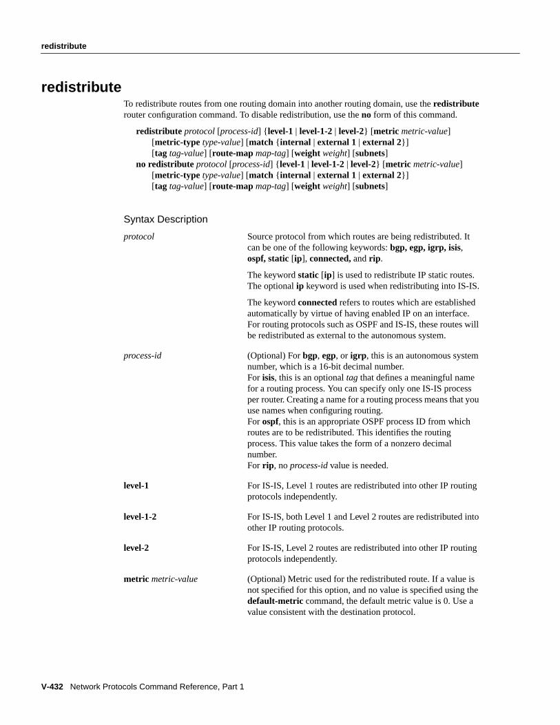
V-432 Network Protocols Command Reference, Part 1
redistribute
redistributeTo redistribute routes from one routing domain into another routing domain, use theredistributerouter configuration command. To disable redistribution, use theno form of this command.
redistribute protocol [process-id] { level-1 | level-1-2| level-2} [ metric metric-value][metric-type type-value] [match { internal | external 1 | external 2}][tag tag-value] [ route-map map-tag] [weight weight] [subnets]
no redistribute protocol [process-id] { level-1 | level-1-2| level-2} [ metric metric-value][metric-type type-value] [match { internal | external 1 | external 2}][tag tag-value] [ route-map map-tag] [weight weight] [subnets]
Syntax Description
protocol Source protocol from which routes are being redistributed. Itcan be one of the following keywords: bgp, egp, igrp, isis,ospf, static [ip], connected, andrip .
The keywordstatic [ip] is used to redistribute IP static routes.The optionalip keyword is used when redistributing into IS-IS.
The keywordconnectedrefers to routes which are establishedautomatically by virtue of having enabled IP on an interface.For routing protocols such as OSPF and IS-IS, these routes willbe redistributed as external to the autonomous system.
process-id (Optional) Forbgp, egp, or igrp , this is an autonomous systemnumber, which is a 16-bit decimal number.For isis, this is an optional tag that defines a meaningful namefor a routing process. You can specify only one IS-IS processper router. Creating a name for a routing process means that youuse names when configuring routing.For ospf, this is an appropriate OSPF process ID from whichroutes are to be redistributed. This identifies the routingprocess. This value takes the form of a nonzero decimalnumber.For rip , noprocess-id value is needed.
level-1 For IS-IS, Level 1 routes are redistributed into other IP routingprotocols independently.
level-1-2 For IS-IS, both Level 1 and Level 2 routes are redistributed intoother IP routing protocols.
level-2 For IS-IS, Level 2 routes are redistributed into other IP routingprotocols independently.
metric metric-value (Optional) Metric used for the redistributed route. If a value isnot specified for this option, and no value is specified using thedefault-metric command, the default metric value is 0. Use avalue consistent with the destination protocol.

redistribute
IP Routing Protocols Commands V-433
metric-type type-value (Optional) For OSPF, the external link type associated with thedefault route advertised into the OSPF routing domain. It can beone of two values:
1—Type 1 external route
2—Type 2 external route
If a metric-type is not specified, the Cisco IOS software adoptsa Type 2 external route.
For IS-IS, it can be one of two values:
internal—IS-IS metric which is < 63.
external—IS-IS metric which is > 64 < 128.
The default isinternal .
match { internal | external 1 |external 2}
(Optional) For OPSF, the criteria by which OSPF routes areredistributed into other routing domains. It an be one of thefollowing:
internal—Routes that are internal to a specific autonomoussystem.
external 1—Routes that are external to the autonomous system,but are imported into OSPF as type 1 external route.
external 2—Routes that are external to the autonomous system,but are imported into OSPF as type 2 external route.
tag tag-value (Optional) 32-bit decimal value attached to each external route.This is not used by the OSPF protocol itself. It may be used tocommunicate information between Autonomous SystemBoundary Routers. If none is specified, then the remoteautonomous system number is used for routes from BGP andEGP; for other protocols, zero (0) is used.
route-map (Optional) Route map should be interrogated to filter theimportation of routes from this source routing protocol to thecurrent routing protocol. If not specified, all routes areredistributed. If this keyword is specified, but no route map tagsare listed, no routes will be imported.
map-tag (Optional) Identifier of a configured route map.
weight weight (Optional) Network weight when redistributing into BGP. Aninteger from 0 to 65535.
subnets (Optional) For redistributing routes into OSPF, the scope ofredistribution for the specified protocol.

V-434 Network Protocols Command Reference, Part 1
redistribute
DefaultsRoute redistribution is disabled.
protocol—No source protocol is defined.process-id—No process ID is defined.metric metric-value—0metric-type type-value—Type 2 external routematch internal | external—internalexternal type-value—internaltag tag-value—If no value is specified, the remote autonomous system number is used for routes
from BGP and EGP; for other protocols, the default is 0.route-map map-tag—If the route-map argument is not entered, all routes are redistributed; if no
map-tag value is entered, no routes are imported.weight weight—No network weight is defined.subnets—No subnets are defined.
Command ModeRouter configuration
Usage GuidelinesThis command first appeared in Cisco IOS Release 10.0.
Changing or disabling any keyword will not affect the state of other keywords.
A router receiving a link-state protocol (LSP) with an internal metric will consider the cost of theroute from itself to the redistributing router plus the advertised cost to reach the destination. Anexternal metric only considers the advertised metric to reach the destination.
Routes learned from IP routing protocols can be redistributed atlevel-1 into an attached area or atlevel-2. The keywordlevel-1-2 allows both in a single command.
Redistributed routing information should always be filtered by thedistribute-list out routerconfiguration command. This ensures that only those routes intended by the administrator are passedalong to the receiving routing protocol.
Whenever you use theredistribute or the default-information router configuration commands toredistribute routes into an OSPF routing domain, the router automatically becomes an AutonomousSystem Boundary Router (ASBR). However, an ASBR does not, by default, generate adefault routeinto the OSPF routing domain.
When routes are redistributed between OSPF processes, no OSPF metrics are preserved.
When routes are redistributed into OSPF and no metric is specified in themetric keyword, thedefault metric that OSPF uses is 20 for routes from all protocols except BGP route, which gets ametric of 1.
When redistributing routes into OSPF, only routes that are not subnetted are redistributed if thesubnets keyword is not specified.
The onlyconnected routes affected by thisredistribute command are the routes not specified bythenetwork command.
You cannot use thedefault-metric command to affect the metric used to advertiseconnected routes.

redistribute
IP Routing Protocols Commands V-435
Note Themetric value specified in theredistribute command supersedes themetric valuespecified using thedefault-metric command.
Default redistribution of IGPs or EGP into BGP is not allowed unlessdefault-informationoriginate is specified.
When routes are redistributed into OSPF and no metric is specified in themetric keyword, thedefault metric that OSPF uses is 20 for routes from all protocols except BGP route, which gets ametric of 1.
ExamplesThe following are examples of the various configurations you would use to redistribute one routingprotocol into another routing protocol.
The following example configuration causes OSPF routes to be redistributed into a BGP domain:
router bgp 109redistribute ospf...
The following example configuration causes IGRP routes to be redistributed into an OSPF domain:
router ospf 110redistribute igrp...
The following example causes the specified IGRP process routes to be redistributed into an OSPFdomain. The IGRP-derived metric will be remapped to 100 and RIP routes to 200.
router ospf 109redistribute igrp 108 metric 100 subnetsredistribute rip metric 200 subnets
In the following example, BGP routes are configured to be redistributed into IS-IS. The link-statecost is specified as 5, and the metric type will be set to external, indicating that it has lower prioritythan internal metrics.
router isisredistribute bgp 120 metric 5 metric-type external
Related Commandsdefault-information originate (BGP)default-information originate (EGP)default-information originate (IS-IS)default-information originate (OSPF)distribute-list outroute-mapshow route-map

V-436 Network Protocols Command Reference, Part 1
route-map
route-mapTo define the conditions for redistributing routes from one routing protocol into another, or to enablepolicy routing, use the route-map global configuration command and thematch andset route-mapconfiguration commands. To delete an entry, use theno route-map command.
route-map map-tag [permit | deny] [sequence-number]no route-mapmap-tag [permit | deny] [sequence-number]
Syntax Description
DefaultNo default is available.
Command ModeGlobal configuration
Usage GuidelinesThis command first appeared in Cisco IOS Release 10.0.
Use route maps to redistribute routes or to subject packets to policy routing. Both purposes aredescribed in this section.
• Redistribution
Use the route-map global configuration command, and thematch andset route-mapconfiguration commands, to define the conditions for redistributing routes from one routingprotocol into another. Eachroute-map command has a list ofmatch andset commands
map-tag Defines a meaningful name for the route map. Theredistribute routerconfiguration command uses this name to reference this route map.Multiple route maps may share the same map tag name.
permit (Optional) If the match criteria are met for this route map, andpermit isspecified, the route is redistributed as controlled by the set actions. In thecase of policy routing, the packet is policy routed.
If the match criteria are not met, andpermit is specified, the next routemap with the same map tag is tested. If a route passes none of the matchcriteria for the set of route maps sharing the same name, it is notredistributed by that set.
deny (Optional) If the match criteria are met for the route map, anddeny isspecified, the route is not redistributed or in the case of policy routing,the packet is not policy routed, and no further route maps sharing thesame map tag name will be examined. If the packet is not policy-routed,it reverts to the normal forwarding algorithm.
sequence-number (Optional) Number that indicates the position a new route map is to havein the list of route maps already configured with the same name. If givenwith the no form of this command, it specifies the position of the routemap that should be deleted.

route-map
IP Routing Protocols Commands V-437
associated with it. Thematch commands specify thematch criteria—the conditions under whichredistribution is allowed for the currentroute-map command. Theset commands specify thesetactions—the particular redistribution actions to perform if the criteria enforced by thematchcommands are met. Theno route-mapcommand deletes the route map.
Thematch route-map configuration command has multiple formats. The relatedmatchcommands are listed in the section “Related Commands for Redistribution.” Thematchcommands can be given in any order, and allmatch commands must “pass” to cause the route tobe redistributed according to theset actionsgiven with theset commands. Theno forms of thematch commands remove the specified match criteria.
Use route maps when you want detailed control over how routes are redistributed betweenrouting processes. The destination routing protocol is the one you specify with therouter globalconfiguration command. The source routing protocol is the one you specify with theredistributerouter configuration command. See the following example as an illustration of how route mapsare configured.
When you are passing routes through a route map, a route map can have several parts. Any routethat does not match at least onematch clause relating to aroute-map command will be ignored;that is, the route will not be advertised for outbound route maps and will not be accepted forinbound route maps. If you want to modify only some data, you must configure a secondroute-map section with an explicit match specified.
• Policy Routing
Another purpose of route maps is to enable policy-routing. Use the ip policy route-mapcommand, in addition to theroute-map command, and thematch and set commands to definethe conditions for policy-routing packets. The relatedmatch andset commands are listed in thesection “Related Commands for Policy Routing.” Thematch commands specify the conditionsunder which policy routing occurs. Theset commands specify the routing actions to perform ifthe criteria enforced by thematch commands are met. You might want to policy-route packetssome way other than the obvious shortest path.
ExamplesThe following example redistributes all OSPF routes into IGRP:
router igrp 109redistribute ospf 110default metric 1000 100 255 1 1500
The following example redistributes RIP routes with a hop count equal to 1 into OSPF. These routeswill be redistributed into OSPF as external link state advertisements with a metric of 5, metric typeof Type 1 and a tag equal to 1.
router ospf 109redistribute rip route-map rip-to-ospf
route-map rip-to-ospf permitmatch metric 1set metric 5set metric-type type1set tag 1

V-438 Network Protocols Command Reference, Part 1
route-map
Related Commands for Redistributionmatch as-pathmatch community-listmatch interfacematch ip addressmatch ip next-hopmatch ip route-sourcematch metricmatch route-typematch tagset as-pathset automatic-tagset communityset levelset local-preferenceset metricset metric-typeset next-hopset originset tagset weightshow route-map
Related Commands for Policy Routingip policy route-mapmatch ip addressmatch lengthset default interfaceset interfaceset ip default next-hopset ip next-hop

router bgp
IP Routing Protocols Commands V-439
router bgpTo configure the Border Gateway Protocol (BGP) routing process, use therouter bgp globalconfiguration command. To remove a routing process, use theno form of this command.
router bgp autonomous-systemno router bgp autonomous-system
Syntax Description
DefaultNo BGP routing process is enabled by default.
Command ModeGlobal configuration
Usage GuidelinesThis command first appeared in Cisco IOS Release 10.0.
This command allows you to set up a distributed routing core that automatically guarantees theloop-free exchange of routing information between autonomous systems.
ExampleThe following example configures a BGP process for autonomous system 120:
router bgp 120
Related Commandsneighbor (EGP, IGRP, RIP)network (BGP)timers bgp
autonomous-system Number of an autonomous system that identifies the router toother BGP routers and tags the routing information passedalong.

V-440 Network Protocols Command Reference, Part 1
router egp
router egpTo configure the Exterior Gateway Protocol (EGP) routing process, use therouter egp globalconfiguration command. To turn off an EGP routing process, use theno router egp command.
router egp remote-asno router egpremote-as
Syntax Description
DefaultNo EGP routing process is defined.
Command ModeGlobal configuration
Usage GuidelinesThis command first appeared in Cisco IOS Release 10.0.
You must specify the autonomous system number before starting EGP. The local autonomous systemnumber will be included in EGP messages sent by the Cisco IOS software. The software does notinsist that the actual remote autonomous system number match the configured autonomous systemnumbers. The output from thedebug ip-egp EXEC command will advise of any discrepancies.
ExampleThe following example assigns a router to autonomous system 109 and is peering with routers inautonomous system 164:
autonomous-system 109router egp 164
Related Commandsautonomous-system (EGP)neighbor (EGP, IGRP, RIP)network (EGP)timers egp
remote-as Autonomous system number the router expects its peers to beadvertising in their EGP messages.

router egp 0
IP Routing Protocols Commands V-441
router egp 0To specify that a router should be considered a core gateway, use therouter egp 0 globalconfiguration command. To disable this function, use theno form of this command.
router egp 0no router egp 0
Syntax DescriptionThis command has no arguments or keywords.
DefaultDisabled
Command ModeGlobal configuration
Usage GuidelinesThis command first appeared in Cisco IOS Release 10.0.
Core gateways are central clearinghouses of routing information. Only one core gateway process canbe configured in a router.
Therouter egp 0 global configuration command allows a specific router to have an EGP process thatwill enable it to act as a peer with any reachable autonomous system and information is exchangedfreely between autonomous systems.
Normally, an EGP process expects to communicate with neighbors from a single autonomoussystem. Because all neighbors are in the same autonomous system, the EGP process assumes thatthese neighbors all have consistent internal information. Therefore, if the EGP process is informedabout a route from one of its neighbors, it will not send it out to other neighbors.
With core EGP, the assumption is that all neighbors are from different autonomous systems, and allhave inconsistent information. In this case, the EGP process distributes routes from one neighbor toall others (but not back to the originator). This allows the EGP process to be a central clearinghousefor information.
To control how an EGP process determines which neighbors will be treated as peers, use theneighbor anyrouter configuration command with therouter egp 0 global configuration command.
ExampleThe following example illustrates how an EGP core gateway can be configured:
access-list 1 permit 10.0.0.0 0.255.255.255! global access list assignmentrouter egp 0neighbor any 1network 131.108.0.0

V-442 Network Protocols Command Reference, Part 1
router egp 0
Related Commandsneighbor anyneighbor any third-party

router eigrp
IP Routing Protocols Commands V-443
router eigrpTo configure the Enhanced IGRP routing process, use therouter eigrp global configurationcommand. To shut down a routing process, use theno form of this command.
router eigrp process-idno router eigrp process-id
Syntax Description
DefaultDisabled
Command ModeGlobal configuration
Usage GuidelinesThis command first appeared in Cisco IOS Release 10.0.
ExampleThe following example shows how to configure an Enhanced IGRP routing process and assignprocess number 109:
router eigrp 109
Related Commandnetwork (IGRP and Enhanced IGRP)
process-id Number of a process that identifies the routes to the otherEnhanced IGRP routers. It is also used to tag the routinginformation. If you have an autonomous system number, youcan use it for the process number.

V-444 Network Protocols Command Reference, Part 1
router igrp
router igrpTo configure the Interior Gateway Routing Protocol (IGRP) routing process, use therouter igrpglobal configuration command. To shut down an IGRP routing process, use theno form of thiscommand.
router igrp process-idno router igrp process-id
Syntax Description
DefaultNo IGRP routing process is defined.
Command ModeGlobal configuration
Usage GuidelinesThis command first appeared in Cisco IOS Release 10.0.
It is not necessary to have a registered autonomous system number to use IGRP. If you do not havea registered number, you are free to create your own. We recommend that if you do have a registerednumber, you use it to identify the IGRP process.
ExampleThe following example shows how to configure an IGRP routing process and assign processnumber 109:
router igrp 109
Related Commandnetwork (IGRP and Enhanced IGRP)
process-id Number of a process that identifies the routes to the other IGRProuters. It is also used to tag the routing information. If youhave an autonomous system number, you can use it for theprocess number.

router isis
IP Routing Protocols Commands V-445
router isisTo enable the IS-IS routing protocol and to specify an IS-IS process for IP, use therouter isis globalconfiguration command. To disable IS-IS routing, use theno form of this command.
router isis [tag]no router isis [tag]
Syntax Description
DefaultDisabled
Command ModeGlobal configuration
Usage GuidelinesThis command first appeared in Cisco IOS Release 10.0.
You can specify only one IS-IS process per router. Only one IS-IS process is allowed whether yourun it in integrated mode, ISO CLNS only, or IP only.
ExampleThe following example configures the router for IP routing and enables the IS-IS routing protocol:
ip routingrouter isis
Related Commandsip router isisnet
tag (Optional) Meaningful name for a routing process. If it is notspecified, a null tag is assumed and the process is referencedwith a null tag. This name must be unique among all IP routerprocesses for a given router.

V-446 Network Protocols Command Reference, Part 1
router odr
router odrTo configure a router to accept on demand routing (ODR) routes from stub routers, use therouterodr global configuration command. To disable stub routing, use theno form of this command.
router odr process-idno router odr process-id
Syntax Description
DefaultThe router ignores any received ODR information.
Command ModeGlobal configuration
Usage GuidelinesThis command first appeared in Cisco IOS Release 11.2.
Use this command on hub routers to enable ODR to update the routing table with informationlearned via ODR stub routers.
ExampleThe following examples sets up the routers in the distribution list to accept on demand routing routesfrom the specified access list.
router odrdistribute-list 101 inaccess-list 101 permit ip host 10.0.0.1 198.92.110.0 255.255.255.0access-list 101 permit ip 11.1.1.1 255.0.0.0 198.92.111.0 255.255.255.0router ospf 1redistribute odr subnets
Related Commandsdistribute-list indistribute-list outdistancemaximum-pathstimers odr
process-id Number of a process that identifies the routes to the other ODRrouters.
router ospf
IP Routing Protocols Commands V-447
router ospfTo configure an OSPF routing process, use the router ospf global configuration command. Toterminate an OSPF routing process, use theno form of this command.
router ospf process-idno router ospfprocess-id
Syntax Description
DefaultNo OSPF routing process is defined.
Command ModeGlobal configuration
Usage GuidelinesThis command first appeared in Cisco IOS Release 10.0.
You can specify multiple OSPF routing processes in each router.
ExampleThe following example shows how to configure an OSPF routing process and assign a processnumber of 109:
router ospf 109
Related Commandnetwork area
process-id Internally used identification parameter for an OSPF routingprocess. It is locally assigned and can be any positive integer. Aunique value is assigned for each OSPF routing process.
V-448 Network Protocols Command Reference, Part 1
router rip
router ripTo configure the Routing Information Protocol (RIP) routing process, use therouter rip globalconfiguration command. To turn off the RIP routing process, use theno form of this command.
router ripno router rip
Syntax DescriptionThis command has no arguments or keywords.
DefaultNo RIP routing process is defined.
Command ModeGlobal configuration
Usage GuidelinesThis command first appeared in Cisco IOS Release 10.0.
ExampleThe following example shows how to begin the RIP routing process:
router rip
Related Commandnetwork (RIP)

send-lifetime
IP Routing Protocols Commands V-449
send-lifetimeTo set the time period during which an authentication key on a key chain is valid to be sent, use thesend-lifetimekey chain key configuration command. To revert to the default value, use theno formof this command.
send-lifetimestart-time{ infinite | end-time | duration seconds}no send-lifetime [start-time{ infinite | end-time | duration seconds}]
Syntax Description
DefaultForever (The starting time is January 1, 1993, and the ending time is infinite.)
Command ModeKey chain key configuration
Usage GuidelinesThis command first appeared in Cisco IOS Release 11.1.
Currently only RIP Version 2 uses key chains.
Specify astart-time and one of the following:infinite , end-time, orduration seconds.
We recommend running NTP or some other time synchronization method if you intend to setlifetimes on keys.
start-time Beginning time that the key specified by thekey command is valid tobe sent. The syntax can be either of the following:
hh:mm:ss Month date year
hh:mm:ss date Month year
hh—hours
mm—minutes
ss—seconds
date—date (1-31)
Month—first three letters of the month
year—year (four digits)
The default start time and the earliest acceptable date is January 1,1993.
infinite Key is valid to be sent from thestart-time on.
end-time Key is valid to be sent from thestart-time until end-time. The syntax isthe same as that forstart-time.Theend-time must be after thestart-time. The default end time is an infinite time period.
duration seconds Length of time in seconds that the key is valid to be sent.

V-450 Network Protocols Command Reference, Part 1
send-lifetime
ExampleThe following example configures a key chain calledtrees. In this example, the software will alwaysaccept and send willow as a valid key. The key chestnut will be accepted from 1:30 p.m. to 3:30 p.m.and be sent from 2:00 p.m. to 3:00 p.m. The overlap allows for migration of keys or discrepanciesin the router's set time. Likewise, the key birch immediately follows chestnut, and there is a halfhourleeway on each side to handle time-of-day differences.
interface ethernet 0 ip rip authentication key-chain trees ip rip authentication mode md5!router rip network 172.19.0.0 version 2!key chain trees key 1 key-string willow key 2 key-string chestnut accept-lifetime 13:30:00 Jan 25 1996 duration 7200 send-lifetime 14:00:00 Jan 25 1996 duration 3600 key 3 key-string birch accept-lifetime 14:30:00 Jan 25 1996 duration 7200 send-lifetime 15:00:00 Jan 25 1996 duration 3600
Related Commandsaccept-lifetimekeykey chainkey-stringshow key chain

set as-path
IP Routing Protocols Commands V-451
set as-pathTo modify an autonomous system path for BGP routes, use the set as-pathroute map configurationcommand. To not modify the autonomous system path, use theno form of this command.
set as-path { tag | prependas-path-string}no set as-path{ tag | prepend as-path-string}
Syntax Description
DefaultAutonomous system path is not modified.
Command ModeRoute map configuration
Usage GuidelinesThis command first appeared in Cisco IOS Release 11.0.
The only global BGP metric available to influence the best path selection is the AS-PATH length. Byvarying the length of the AS-PATH, a BGP speaker can influence the best path selection by a peerfurther away.
By allowing you to convert the tag into an autonomous system path, theset as-pathtag variation ofthis command modifies the autonomous system length. Theset as-pathprepend variation allows youto “prepend” an arbitrary autonomous system path string to BGP routes. Usually the localautonomous system number is prepended multiple times. This increases the autonomous systempath length.
ExamplesThe following example converts the tag of a redistributed route into an autonomous system path:
route-map set-as-path-from-tagmatch as-path 2set as-path prepend 100 100 100!router bgp 100redistribute ospf 109 route-map set-as-path-from-tag
tag Converts the tag of a route into an autonomous system path. Applies onlywhen redistributing routes into BGP.
prependas-path-string
Appends the string following the keywordprepend to the as-path of theroute that is matched by the route map. Applies to inbound and outboundBGP route maps.
V-452 Network Protocols Command Reference, Part 1
set as-path
The following example prepends 100 100 100 to all the routes advertised to 131.108.1.1:
route-map set-as-pathmatch as-path 1set as-path prepend 100 100 100!router bgp 100neighbor 131.108.1.1 route-map set-as-path out
Related Commandsmatch as-pathmatch community-listmatch interfacematch ip addressmatch ip next-hopmatch ip route-sourcematch metricmatch route-typematch tagroute-mapset automatic-tagset communityset levelset local-preferenceset metricset metric-typeset next-hopset originset tagset weight

set automatic-tag
IP Routing Protocols Commands V-453
set automatic-tagTo automatically compute the tag value, use theset automatic-tag route-map configurationcommand. To disable this function, use theno form of this command.
set automatic-tagno set automatic-tag
Syntax DescriptionThis command has no arguments or keywords.
DefaultDisabled
Command ModeRoute-map configuration
Usage GuidelinesThis command first appeared in Cisco IOS Release 10.0.
You must have a match clause (even if it points to a “permit everything” list) if you want to set tags.
Use the route-map global configuration command, and thematch andsetroute-map configurationcommands, to define the conditions for redistributing routes from one routing protocol into another.Eachroute-map command has a list ofmatch andset commands associated with it. Thematchcommands specify thematch criteria—the conditions under which redistribution is allowed for thecurrentroute-map command. Theset commands specify theset actions—the particularredistribution actions to perform if the criteria enforced by thematch commands are met. Thenoroute-map command deletes the route map.
Theset route-map configuration commands specify the redistributionset actions to be performedwhen all of a route map’s match criteria are met. When all match criteria are met, all set actions areperformed.
ExampleIn the following example, the Cisco IOS software is configured to automatically compute the tagvalue for the BGP learned routes:
route-map tagmatch as path 10set automatic-tag!router bgp 100table-map tag

V-454 Network Protocols Command Reference, Part 1
set automatic-tag
Related Commandsmatch as-pathmatch community-listmatch interfacematch ip addressmatch ip next-hopmatch ip route-sourcematch metricmatch route-typematch tagroute-mapset as-pathset communityset levelset local-preferenceset metricset metric-typeset next-hopset originset tagset weight

set community
IP Routing Protocols Commands V-455
set communityTo set the BGP COMMUNITIES attribute, use theset community route-map configurationcommand. To delete the entry, use theno form of this command.
set communitycommunity-number [additive]no set communitycommunity-number [additive]
Syntax Description
DefaultNo BGP COMMUNITIES attributes exist.
Command ModeRoute-map configuration
Usage GuidelinesThis command first appeared in Cisco IOS Release 10.3.
You must have a match clause (even if it points to a “permit everything” list) if you want to set tags.
Use the route-map global configuration command, and thematch andset route-map configurationcommands, to define the conditions for redistributing routes from one routing protocol into another.Eachroute-map command has a list ofmatch andset commands associated with it. Thematchcommands specify thematch criteria—the conditions under which redistribution is allowed for thecurrentroute-map command. Theset commands specify theset actions—the particularredistribution actions to perform if the criteria enforced by thematch commands are met. Thenoroute-map command deletes the route map.
Theset route-map configuration commands specify the redistributionset actions to be performedwhen all of a route map’s match criteria are met. When all match criteria are met, all set actions areperformed.
ExampleIn the following example, routes that pass the autonomous system path access list 1 have thecommunity set to 109. Routes that pass the autonomous system path access list 2 have thecommunity set to no-export (these routes will not be advertised to any EBGP peers).
route-map set_community 10 permitmatch as-path 1set community 109
route-map set_community 20 permitmatch as-path 2set community no-export
community-number Valid values are 1 to 4294967200,no-export, orno-advertise.
additive (Optional) Adds the community to the already existingcommunities.

V-456 Network Protocols Command Reference, Part 1
set community
Related Commandsip cgmpmatch community-listroute-map

set default interface
IP Routing Protocols Commands V-457
set default interfaceTo indicate where to output packets that pass a match clause of a route map for policy routing andhave no explicit route to the destination, use theset default interfaceroute-map configurationcommand. To delete an entry, use theno form of this command.
set default interfacetype number[... type number]no set default interfacetype number[... type number]
Syntax Description
DefaultDisabled
Command ModeRoute-map configuration
Usage GuidelinesThis command first appeared in Cisco IOS Release 11.0.
Use this command to provide certain users a different default route. If the Cisco IOS software hasno explicit route for the destination, then it routes the packet to this interface. The first interfacespecified with theset default interface command that is up is used. The optionally specifiedinterfaces are tried in turn.
Use the ip policy route-mapinterface configuration command, theroute-map global configurationcommand, and thematch andset route-map configuration commands, to define the conditions forpolicy routing packets. Theip policy route-map command identifies a route map by name. Eachroute-map command has a list ofmatch andset commands associated with it. Thematchcommands specify thematch criteria—the conditions under which policy routing occurs. Thesetcommands specify theset actions—the particular routing actions to perform if the criteria enforcedby thematch commands are met.
The set clauses can be used in conjunction with one another. They are evaluated in the followingorder:
set ip next-hopset interfaceset ip default next-hopset default interface
type Interface type, used with the interface number, to which packets are output.
number Interface number, used with the interface type, to which packets are output.

V-458 Network Protocols Command Reference, Part 1
set default interface
ExampleIn the following example, packets that have a Level 3 length of 3 to 50 bytes and for which thesoftware has no explicit route to the destination are output to Ethernet interface 0:
interface serial 0ip policy route-map brighton!route-map brightonmatch length 3 50set default interface ethernet 0
Related Commandsip policy route-mapmatch ip addressmatch lengthroute-mapset interfaceset ip default next-hopset ip next-hop

set interface
IP Routing Protocols Commands V-459
set interfaceTo indicate where to output packets that pass a match clause of route map for policy routing, use theset interfaceroute-map configuration command. To delete an entry, use theno form of thiscommand.
set interfacetype number[... type number]no set interfacetype number[... type number]
Syntax Description
DefaultDisabled
Command ModeRoute-map configuration
Usage GuidelinesThis command first appeared in Cisco IOS Release 11.0.
Use the ip policy route-mapinterface configuration command, theroute-map global configurationcommand, and thematch andset route-map configuration commands, to define the conditions forpolicy routing packets. Theip policy route-map command identifies a route map by name. Eachroute-map command has a list ofmatch andset commands associated with it. Thematchcommands specify thematch criteria—the conditions under which policy routing occurs. Thesetcommands specify theset actions—the particular routing actions to perform if the criteria enforcedby thematch commands are met.
If the first interface specified with theset interface command is down, the optionally specifiedinterfaces are tried in turn.
The set clauses can be used in conjunction with one another. They are evaluated in the followingorder:
set ip next-hopset interfaceset ip default next-hopset default interface
A useful next hop implies an interface. As soon as a next hop and an interface are found, the packetis routed.
Specifyingset interface null 0 is a way to write a policy that the packet be dropped and an“unreachable” message be generated.
type Interface type, used with the interface number, to which packets are output.
number Interface number, used with the interface type, to which packets are output.

V-460 Network Protocols Command Reference, Part 1
set interface
ExampleIn the following example, packets with a Level 3 length of 3 to 50 bytes are output to Ethernetinterface 0:
interface serial 0ip policy route-map testing!route-map testingmatch length 3 50set interface ethernet 0
Related Commandsip policy route-mapmatch ip addressmatch lengthroute-mapset default interfaceset ip default next-hopset ip next-hop
set ip default next-hop
IP Routing Protocols Commands V-461
set ip default next-hopTo indicate where to output packets that pass a match clause of a route map for policy routing andfor which the Cisco IOS software has no explicit route to a destination, use theset ip defaultnext-hop route-map configuration command. To delete an entry, use theno form of this command.
set ip default next-hopip-address[... ip-address]no set ip default next-hopip-address[... ip-address]
Syntax Description
DefaultDisabled
Command ModeRoute-map configuration
Usage GuidelinesThis command first appeared in Cisco IOS Release 11.0.
Use this command to provide certain users a different default route. If the software has no explicitroute for the destination in the packet, then it routes the packet to this next hop. The first next hopspecified with theset ip default next-hopcommand that appears to be adjacent to the router is used.The optional specified IP addresses are tried in turn.
Use the ip policy route-mapinterface configuration command, theroute-map global configurationcommand, and thematch andset route-map configuration commands, to define the conditions forpolicy routing packets. Theip policy route-map command identifies a route map by name. Eachroute-map command has a list ofmatch andset commands associated with it. Thematchcommands specify thematch criteria—the conditions under which policy routing occurs. Thesetcommands specify theset actions—the particular routing actions to perform if the criteria enforcedby thematch commands are met.
The set clauses can be used in conjunction with one another. They are evaluated in the followingorder:
set ip next-hopset interfaceset ip default next-hopset default interface
ip-address IP address of the next hop to which packets are output. It need not be anadjacent router.
V-462 Network Protocols Command Reference, Part 1
set ip default next-hop
ExampleThe following example provides two sources with equal access to two different service providers.Packets arriving on async interface 1 from the source 1.1.1.1 are sent to the router at 6.6.6.6 if thesoftware has no explicit route for the packet’s destination. Packets arriving from the source 2.2.2.2are sent to the router at 7.7.7.7 if the software has no explicit route for the packet’s destination. Allother packets for which the software has no explicit route to the destination are discarded.
access-list 1 permit ip 1.1.1.1 0.0.0.0access-list 2 permit ip 2.2.2.2 0.0.0.0!interface async 1ip policy route-map equal-access!route-map equal-access permit 10match ip address 1set ip default next-hop 6.6.6.6route-map equal-access permit 20match ip address 2set ip default next-hop 7.7.7.7route-map equal-access permit 30set default interface null0
Related Commandsip policy route-mapmatch ip addressmatch lengthroute-mapset default interfaceset interfaceset ip next-hop

set ip next-hop
IP Routing Protocols Commands V-463
set ip next-hopTo indicate where to output packets that pass a match clause of a route map for policy routing, usetheset ip next-hoproute-map configuration command. To delete an entry, use theno form of thiscommand.
set ip next-hopip-address[... ip-address]no set ip next-hopip-address[... ip-address]
Syntax Description
DefaultDisabled
Command ModeRoute-map configuration
Usage GuidelinesThis command first appeared in Cisco IOS Release 11.0.
Use the ip policy route-mapinterface configuration command, theroute-map global configurationcommand, and thematch andset route-map configuration commands, to define the conditions forpolicy routing packets. Theip policy route-map command identifies a route map by name. Eachroute-map command has a list ofmatch andset commands associated with it. Thematchcommands specify thematch criteria—the conditions under which policy routing occurs. Thesetcommands specify theset actions—the particular routing actions to perform if the criteria enforcedby thematch commands are met.
If the first next hop specified with theset ip next-hopcommand is down, the optionally specified IPaddresses are tried in turn.
The set clauses can be used in conjunction with one another. They are evaluated in the followingorder:
set ip next-hopset interfaceset ip default next-hopset default interface
ExampleIn the following example, packets with a Level 3 length of 3 to 50 bytes are output to the router atIP address 161.14.2.2:
interface serial 0ip policy route-map thataway!route-map thatawaymatch length 3 50set ip next-hop 161.14.2.2
ip-address IP address of the next hop to which packets are output. It need not be anadjacent router.

V-464 Network Protocols Command Reference, Part 1
set ip next-hop
Related Commandsip policy route-mapmatch ip addressmatch lengthroute-mapset default interfaceset interfaceset ip default next-hop

set level
IP Routing Protocols Commands V-465
set levelTo indicate where to import routes, use theset level route-map configuration command. To delete anentry, use theno form of this command.
set level { level-1 | level-2 | level-1-2 | stub-area | backbone}no set level { level-1 | level-2 | level-1-2 | stub-area | backbone}
Syntax Description
DefaultsDisabled
For IS-IS destinations, the default value islevel-2. For OSPF destinations, the default value isbackbone.
Command ModeRoute-map configuration
Usage GuidelinesThis command first appeared in Cisco IOS Release 10.0.
Use the route-map global configuration command, and thematch andset route-map configurationcommands, to define the conditions for redistributing routes from one routing protocol into another.Eachroute-map command has a list ofmatch andset commands associated with it. Thematchcommands specify thematch criteria—the conditions under which redistribution is allowed for thecurrentroute-map command. Theset commands specify theset actions—the particularredistribution actions to perform if the criteria enforced by thematch commands are met. Thenoroute-map command deletes the route map.
Theset route-map configuration commands specify the redistributionset actions to be performedwhen all of a route map’s match criteria are met. When all match criteria are met, all set actions areperformed.
ExampleIn the following example, routes will be imported into the Level 1 area:
route-map nameset level level-l
level-1 Imports routes into a Level-1 area.
level-2 Imports routes into Level-2 subdomain.
level-1-2 Imports routes into Level-1 and Level-2.
stub-area Imports routes into OSPF NSSA area.
backbone Imports routes into OSPF backbone area.

V-466 Network Protocols Command Reference, Part 1
set level
Related Commandsmatch as-pathmatch community-listmatch interfacematch ip addressmatch ip next-hopmatch ip route-sourcematch metricmatch route-typematch tagroute-mapset as-pathset automatic-tagset communityset local-preferenceset metricset metric-typeset next-hopset originset tagset weight

set local-preference
IP Routing Protocols Commands V-467
set local-preferenceTo specify a preference value for the autonomous system path, use the set local-preferenceroute-map configuration command. To delete an entry, use the no form of this command.
set local-preferencevalueno set local-preferencevalue
Syntax Description
DefaultPreference value of 100
Command ModeRoute-map configuration
Usage GuidelinesThis command first appeared in Cisco IOS Release 10.0.
The preference is sent only to all routers in the local autonomous system.
You must have a match clause (even if it points to a “permit everything” list) if you want to set tags.
Use the route-map global configuration command, and thematch andset route-map configurationcommands, to define the conditions for redistributing routes from one routing protocol into another.Eachroute-map command has a list ofmatch andset commands associated with it. Thematchcommands specify thematch criteria—the conditions under which redistribution is allowed for thecurrentroute-map command. Theset commands specify theset actions—the particularredistribution actions to perform if the criteria enforced by thematch commands are met. Thenoroute-map command deletes the route map.
Theset route-map configuration commands specify the redistributionset actions to be performedwhen all of a route map’s match criteria are met. When all match criteria are met, all set actions areperformed.
You can change the default preference value with the bgp default local-preferencecommand.
ExampleIn the following example, the local preference is set to 100 for all routes that are included in accesslist 1:
route-map map-preferencematch as-path 1set local-preference 100
value Preference value. An integer from 0 to 4294967295.

V-468 Network Protocols Command Reference, Part 1
set local-preference
Related Commandsbgp default local-preferencematch as-pathmatch community-listmatch interfacematch ip addressmatch ip next-hopmatch ip route-sourcematch metricmatch route-typematch tagroute-mapset as-pathset automatic-tagset communityset levelset metricset metric-typeset next-hopset originset tagset weight

set metric
IP Routing Protocols Commands V-469
set metricTo set the metric value for the destination routing protocol, use theset metric route-mapconfiguration command. To return to the default metric value, use theno form of this command.
set metricmetric-valueno set metricmetric-value
Syntax Description
DefaultDefault metric value.
Command ModeRoute-map configuration
Usage GuidelinesThis command first appeared in Cisco IOS Release 10.0.
Use the route-map global configuration command, and thematch andset route-map configurationcommands, to define the conditions for redistributing routes from one routing protocol into another.Eachroute-map command has a list ofmatch andset commands associated with it. Thematchcommands specify thematch criteria—the conditions under which redistribution is allowed for thecurrentroute-map command. Theset commands specify theset actions—the particularredistribution actions to perform if the criteria enforced by thematch commands are met. Thenoroute-map command deletes the route map.
Theset route-map configuration commands specify the redistributionset actions to be performedwhen all of a route map’s match criteria are met. When all match criteria are met, all set actions areperformed.
ExampleIn the following example, the metric value for the destination routing protocol is set to 100:
route-map set-metricset metric 100
Related Commandsmatch as-pathmatch community-listmatch interfacematch ip addressmatch ip next-hopmatch ip route-sourcematch metricmatch route-type
metric-value Metric value or IGRP bandwidth in kilobits per second. It canbe an integer from -294967295 to 294967295.

V-470 Network Protocols Command Reference, Part 1
set metric
match tagroute-mapset as-pathset automatic-tagset communityset levelset local-preferenceset metric-typeset next-hopset originset tagset weight

set metric-type
IP Routing Protocols Commands V-471
set metric-typeTo set the metric type for the destination routing protocol, use theset metric-type route-mapconfiguration command. To return to the default, use theno form of this command.
set metric-type { internal | external | type-1 | type-2}no set metric-type { internal | external | type-1 | type-2}
Syntax Description
DefaultDisabled
Command ModeRoute-map configuration
Usage GuidelinesThis command first appeared in Cisco IOS Release 10.0.
Use the route-map global configuration command withmatch andset route-map configurationcommands to define the conditions for redistributing routes from one routing protocol into another.Eachroute-map command has a list ofmatch andset commands associated with it. Thematchcommands specify thematch criteria—the conditions under which redistribution is allowed for thecurrentroute-map command. Theset commands specify theset actions—the particularredistribution actions to perform if the criteria enforced by thematch commands are met. Thenoroute-map command deletes the route map.
Theset route-map configuration commands specify the redistributionset actions to be performedwhen all of a route map’s match criteria are met. When all match criteria are met, all set actions areperformed.
ExampleIn the following example, the metric type of the destination protocol is set to OSPF external type 1:
route-map map-typeset metric-type type-1
internal IS-IS internal metric.
external IS-IS external metric.
type-1 OSPF external type 1 metric.
type-2 OSPF external type 2 metric.

V-472 Network Protocols Command Reference, Part 1
set metric-type
Related Commandsmatch as-pathmatch community-listmatch interfacematch ip addressmatch ip next-hopmatch ip route-sourcematch metricmatch route-typematch tagroute-mapset as-pathset automatic-tagset communityset levelset local-preferenceset metricset next-hopset originset tagset weight

set next-hop
IP Routing Protocols Commands V-473
set next-hopTo specify the address of the next hop, use the set next-hop route-map configuration command. Todelete an entry, use theno form of this command.
set next-hopnext-hopno set next-hopnext-hop
Syntax Description
DefaultDefault next-hop address.
Command ModeRoute-map configuration
Usage GuidelinesThis command first appeared in Cisco IOS Release 10.0.
You must have a match clause (even if it points to a “permit everything” list) if you want to set tags.
Use the route-map global configuration command withmatch andset route-map configurationcommands to define the conditions for redistributing routes from one routing protocol into another.Eachroute-map command has a list ofmatch andset commands associated with it. Thematchcommands specify thematch criteria—the conditions under which redistribution is allowed for thecurrentroute-map command. Theset commands specify theset actions—the particularredistribution actions to perform if the criteria enforced by thematch commands are met. Thenoroute-map command deletes the route map.
Theset route-map configuration commands specify the redistributionset actions to be performedwhen all of a route map’s match criteria are met. When all match criteria are met, all set actions areperformed.
ExampleIn the following example, routes that pass the access list have the next hop set to 198.92.70.24:
route-map map_hopmatch address 5set next-hop 198.92.70.24
next-hop IP address of the next hop router.

V-474 Network Protocols Command Reference, Part 1
set next-hop
Related Commandsmatch as-pathmatch community-listmatch interfacematch ip addressmatch ip next-hopmatch ip route-sourcematch metricmatch route-typematch tagroute-mapset as-pathset automatic-tagset communityset levelset local-preferenceset metricset metric-typeset originset tagset weight

set origin
IP Routing Protocols Commands V-475
set originTo set the BGP origin code, use theset origin route-map configuration command. To delete an entry,use theno form of this command.
set origin { igp | egpautonomous-system| incomplete}
Syntax Description
DefaultDefault origin, based on route in main IP routing table.
Command ModeRoute-map configuration
Usage GuidelinesThis command first appeared in Cisco IOS Release 10.0.
You must have a match clause (even if it points to a “permit everything” list) if you want to set tags.
Use the route-map global configuration command withmatch andset route-map configurationcommands to define the conditions for redistributing routes from one routing protocol into another.Eachroute-map command has a list ofmatch andset commands associated with it. Thematchcommands specify thematch criteria—the conditions under which redistribution is allowed for thecurrentroute-map command. Theset commands specify theset actions—the particularredistribution actions to perform if the criteria enforced by thematch commands are met. Thenoroute-map command deletes the route map.
Theset route-map configuration commands specify the redistributionset actions to be performedwhen all of a route map’s match criteria are met. When all match criteria are met, all set actions areperformed.
ExampleIn the following example, routes that pass the route map have the origin set to IGP:
route-map set_originmatch as-path 10set origin igp
igp Remote IGP.
egp Local EGP.
autonomous-system Remote autonomous system. This is an integer from 0 to 65535.
incomplete Unknown heritage.

V-476 Network Protocols Command Reference, Part 1
set origin
Related Commandsmatch as-pathmatch community-listmatch interfacematch ip addressmatch ip next-hopmatch ip route-sourcematch metricmatch route-typematch tagroute-mapset as-pathset automatic-tagset communityset levelset local-preferenceset metricset metric-typeset next-hopset tagset weight

set tag
IP Routing Protocols Commands V-477
set tagTo set a tag value of the destination routing protocol, use theset tag route-map configurationcommand. To delete the entry, use theno form of this command.
set tagtag-valueno set tagtag-value
Syntax Description
DefaultIf not specified, the default action is toforward the tag in the source routing protocol onto the newdestination protocol.
Command ModeRoute-map configuration
Usage GuidelinesThis command first appeared in Cisco IOS Release 10.0.
Use the route-map global configuration command withmatch andset route-map configurationcommands to define the conditions for redistributing routes from one routing protocol into another.Eachroute-map command has a list ofmatch andset commands associated with it. Thematchcommands specify thematch criteria—the conditions under which redistribution is allowed for thecurrentroute-map command. Theset commands specify theset actions—the particularredistribution actions to perform if the criteria enforced by thematch commands are met. Thenoroute-map command deletes the route map.
Theset route-map configuration commands specify the redistributionset actions to be performedwhen all of a route map’s match criteria are met. When all match criteria are met, all set actions areperformed.
ExampleIn the following example, the tag value of the destination routing protocol is set to 5:
route-map tagset tag 5
Related Commandsmatch as-pathmatch community-listmatch interfacematch ip addressmatch ip next-hopmatch ip route-sourcematch metricmatch route-type
tag-value Name for the tag. Integer from 0 to 4294967295.

V-478 Network Protocols Command Reference, Part 1
set tag
match tagroute-mapset as-pathset automatic-tagset communityset levelset local-preferenceset metricset metric-typeset next-hopset originset weight

set weight
IP Routing Protocols Commands V-479
set weightTo specify the BGP weight for the routing table, use theset weight route-map configurationcommand. To delete an entry, use theno form of this command.
set weightweightno set weightweight
Syntax Description
DefaultThe weight is not changed by the specified route map.
Command ModeRoute-map configuration
Usage GuidelinesThis command first appeared in Cisco IOS Release 10.0.
You must have a match clause (even if it points to a “permit everything” list) if you want to set tags.
The implemented weight is based on the first matched autonomous system path. Weights indicatedwhen an autonomous system path is matched override the weights assigned by globalneighborcommands. In other words, the weights assigned with thematch as-path and set weight route-mapcommands override the weights assigned using the neighbor weight andneighbor filter-listcommands.
ExampleIn the following example, the BGP weight for the routes matching the autonomous system pathaccess list is set to 200:
route-map set-weightmatch as-path 10set weight 200
Related Commandsmatch as-pathmatch community-listmatch interfacematch ip addressmatch ip next-hopmatch ip route-sourcematch metricmatch route-typematch tagroute-mapset as-path
weight Weight value. It can be an integer from 0 to 65535.

V-480 Network Protocols Command Reference, Part 1
set weight
set automatic-tagset communityset levelset local-preferenceset metricset metric-typeset next-hopset originset tag

show ip bgp
IP Routing Protocols Commands V-481
show ip bgpTo display entries in the BGP routing table, use theshow ip bgpEXEC command.
show ip bgp[network] [network-mask] [ longer-prefixes]
Syntax Description
Command ModeEXEC
Usage GuidelinesThis command first appeared in Cisco IOS Release 10.0.
Sample DisplayThe following is sample output from theshow ip bgp command:
Router# show ip bgp
BGP table version is 716977, local router ID is 193.0.32.1Status codes: s suppressed, * valid, > best, i - internalOrigin codes: i - IGP, e - EGP, ? - incomplete
Network Next Hop Metric LocPrf Weight Path* i3.0.0.0 193.0.22.1 0 100 0 1800 1239 ?*>i 193.0.16.1 0 100 0 1800 1239 ?* i6.0.0.0 193.0.22.1 0 100 0 1800 690 568 ?*>i 193.0.16.1 0 100 0 1800 690 568 ?* i7.0.0.0 193.0.22.1 0 100 0 1800 701 35 ?*>i 193.0.16.1 0 100 0 1800 701 35 ?* 198.92.72.24 0 1878 704 701 35 ?* i8.0.0.0 193.0.22.1 0 100 0 1800 690 560 ?*>i 193.0.16.1 0 100 0 1800 690 560 ?* 198.92.72.24 0 1878 704 701 560 ?* i13.0.0.0 193.0.22.1 0 100 0 1800 690 200 ?*>i 193.0.16.1 0 100 0 1800 690 200 ?* 198.92.72.24 0 1878 704 701 200 ?* i15.0.0.0 193.0.22.1 0 100 0 1800 174 ?*>i 193.0.16.1 0 100 0 1800 174 ?* i16.0.0.0 193.0.22.1 0 100 0 1800 701 i*>i 193.0.16.1 0 100 0 1800 701 i* 198.92.72.24 0 1878 704 701 i
Table 33 describes significant fields shown in the display.
network (Optional) Network number, entered to display a particular network inthe BGP routing table.
network-mask (Optional) Displays all BGP routes matching the address/mask pair.
longer-prefixes (Optional) Displays route and more specific routes.

V-482 Network Protocols Command Reference, Part 1
show ip bgp
The following is sample output from theshow ip bgp command when you specifylonger-prefixes:
Router# show ip bgp 198.92.0.0 255.255.0.0 longer-prefixes
BGP table version is 1738, local router ID is 198.92.72.24Status codes: s suppressed, * valid, > best, i - internalOrigin codes: i - IGP, e - EGP, ? - incomplete
Network Next Hop Metric LocPrf Weight Path*> 198.92.0.0 198.92.72.30 8896 32768 ?* 198.92.72.30 0 109 108 ?*> 198.92.1.0 198.92.72.30 8796 32768 ?* 198.92.72.30 0 109 108 ?*> 198.92.11.0 198.92.72.30 42482 32768 ?* 198.92.72.30 0 109 108 ?*> 198.92.14.0 198.92.72.30 8796 32768 ?* 198.92.72.30 0 109 108 ?*> 198.92.15.0 198.92.72.30 8696 32768 ?* 198.92.72.30 0 109 108 ?*> 198.92.16.0 198.92.72.30 1400 32768 ?
Table 33 Show IP BGP Field Descriptions
Field Description
BGP table version Internal version number of the table. This number is incrementedwhenever the table changes.
local router ID IP address of the router.
Status codes Status of the table entry. The status is displayed at the beginning ofeach line in the table. It can be one of the following values:
s suppressed Entry is suppressed.
* valid Entry is valid.
> best Entry is the best to use for that network.
i -internal Entry learned via an internal BGP session.
Origin codes Indicates the origin of the entry. The origin code is placed at the end ofeach line in the table. It can be one of the following values:
i - IGP Entry originated from IGP and was advertised with anetwork routerconfiguration command.
e - EGP Entry originated from EGP.
? - incomplete Origin of the path is not clear Usually, this is a router that isredistributed into BGP from an IGP.
Network IP address of a network entity.
Next Hop IP address of the next system that is used when forwarding a packet tothe destination network. An entry of 0.0.0.0 indicates that the routerhas some non-BGP routes to this network.
Metric If shown, this is the value of the interautonomous system metric. Thisis frequently not used.
LocPrf Local preference value as set with theset local-preference route-mapconfiguration command. The default value is 100.
Weight Weight of the route as set via autonomous system filters.
Path Autonomous system paths to the destination network. There can beone entry in this field for each autonomous system in the path.

show ip bgp
IP Routing Protocols Commands V-483
* 198.92.72.30 0 109 108 ?*> 198.92.17.0 198.92.72.30 1400 32768 ?* 198.92.72.30 0 109 108 ?*> 198.92.18.0 198.92.72.30 8876 32768 ?* 198.92.72.30 0 109 108 ?*> 198.92.19.0 198.92.72.30 8876 32768 ?* 198.92.72.30 0 109 108 ?

V-484 Network Protocols Command Reference, Part 1
show ip bgp cidr-only
show ip bgp cidr-onlyTo display routes with nonnatural network masks (that is, classless interdomain routing, or CIDR),use theshow ip bgp cidr-only privileged EXEC command.
show ip bgp cidr-only
Syntax DescriptionThis command has no arguments or keywords.
Command ModePrivileged EXEC
Usage Guidelines
This command first appeared in Cisco IOS Release 10.0.
Sample DisplayThe following is sample output from the show ip bgp cidr-onlycommand:
Router# show ip bgp cidr-only
BGP table version is 220, local router ID is 198.92.73.131Status codes: s suppressed, * valid, > best, i - internalOrigin codes: i - IGP, e - EGP, ? - incomplete
Network Next Hop Metric LocPrf Weight Path*> 192.0.0.0/8 198.92.72.24 0 1878 ?*> 198.92.0.0/16 198.92.72.30 0 108 ?
Table 34 describes significant fields shown in the display.
Table 34 Show IP BGP CIDR-Only Field Descriptions
Field Description
BGP table version is 220 Internal version number for the table. This is incremented any time thetable changes.
local access server ID An Internet address of the access server.
Status codes s—The table entry is suppressed.
*—The table entry is valid.
>—The table entry is the best entry to use for that network.
i—The table entry was learned via an internal BGP session.
Network Internet address of the network the entry describes.
Next Hop IP address of the next system to use when forwarding a packet to thedestination network. An entry of 0.0.0.0 indicates that the access serverhas some non-BGP route to this network.
LocPrf Local preference value. Default is 100.
Metric If shown, this is the value of the interautonomous system metric. Thisis frequently not used.
Weight Set through the use of autonomous system filters.

show ip bgp cidr-only
IP Routing Protocols Commands V-485
Path Autonomous system paths to the destination network. There can beone entry in this field for each autonomous system in the path. At theend of the path is the origin code for the path.
i—The entry was originated with the IGP and advertised with anetwork router configuration command.
e—The route originated with EGP.
?—The origin of the path is not clear. Usually this is a path that isredistributed into BGP from an IGP.
Table 34 Show IP BGP CIDR-Only Field Descriptions (Continued)
Field Description

V-486 Network Protocols Command Reference, Part 1
show ip bgp community
show ip bgp communityTo display routes that belong to specified BGP communities, use theshow ip bgp communityEXEC command.
show ip bgp communitycommunity-number[exact]
Syntax Description
Command ModeEXEC
Usage GuidelinesThis command first appeared in Cisco IOS Release 10.3.
Sample DisplayThe following is sample output from theshow ip bgp communitycommand:
Router# show ip bgp community 10
BGP table version is 716977, local router ID is 193.0.32.1Status codes: s suppressed, * valid, > best, i - internalOrigin codes: i - IGP, e - EGP, ? - incomplete
Network Next Hop Metric LocPrf Weight Path* i3.0.0.0 193.0.22.1 0 100 0 1800 1239 ?*>i 193.0.16.1 0 100 0 1800 1239 ?* i6.0.0.0 193.0.22.1 0 100 0 1800 690 568 ?*>i 193.0.16.1 0 100 0 1800 690 568 ?* i7.0.0.0 193.0.22.1 0 100 0 1800 701 35 ?*>i 193.0.16.1 0 100 0 1800 701 35 ?* 198.92.72.24 0 1878 704 701 35 ?* i8.0.0.0 193.0.22.1 0 100 0 1800 690 560 ?*>i 193.0.16.1 0 100 0 1800 690 560 ?* 198.92.72.24 0 1878 704 701 560 ?* i13.0.0.0 193.0.22.1 0 100 0 1800 690 200 ?*>i 193.0.16.1 0 100 0 1800 690 200 ?* 198.92.72.24 0 1878 704 701 200 ?* i15.0.0.0 193.0.22.1 0 100 0 1800 174 ?*>i 193.0.16.1 0 100 0 1800 174 ?* i16.0.0.0 193.0.22.1 0 100 0 1800 701 i*>i 193.0.16.1 0 100 0 1800 701 i* 198.92.72.24 0 1878 704 701 i
Table 35 describes significant fields shown in the display.
community-number Valid value is community number in the range 1 to4294967200,internet, no-export, orno-advertise.
exact (Optional) Displays only routes that have exactly the samespecified communities.

show ip bgp community
IP Routing Protocols Commands V-487
Table 35 Show IP BGP Community Field Descriptions
Field Description
BGP table version Internal version number of the table. This number is incrementedwhenever the table changes.
local router ID IP address of the router.
Status codes Status of the table entry. The status is displayed at the beginning ofeach line in the table. It can be one of the following values:
s suppressed Entry is suppressed.
* valid Entry is valid.
> best Entry is the best to use for that network.
i -internal Entry learned via an internal BGP session.
Origin codes Indicates the origin of the entry. The origin code is placed at the end ofeach line in the table. It can be one of the following values:
i - IGP Entry originated from IGP and was advertised with anetwork routerconfiguration command.
e - EGP Entry originated from EGP.
? - incomplete Origin of the path is not clear Usually, this is a router that isredistributed into BGP from an IGP.
Network IP address of a network entity.
Next Hop IP address of the next system that is used when forwarding a packet tothe destination network. An entry of 0.0.0.0 indicates that the routerhas some non-BGP routes to this network.
Metric If shown, this is the value of the interautonomous system metric. Thisis frequently not used.
LocPrf Local preference value as set with theset local-preference route-mapconfiguration command. The default value is 100.
Weight Weight of the route as set via autonomous system filters.
Path Autonomous system paths to the destination network. There can beone entry in this field for each autonomous system in the path.
V-488 Network Protocols Command Reference, Part 1
show ip bgp community-list
show ip bgp community-listTo display routes that are permitted by the BGP community list, use theshow ip bgpcommunity-list EXEC command.
show ip bgp community-listcommunity-list-number [exact]
Syntax Description
Command ModeEXEC
Usage GuidelinesThis command first appeared in Cisco IOS Release 10.3.
Sample DisplayThe following is sample output of theshow ip bgp community-listcommand:
Router# show ip bgp community-list 20
BGP table version is 716977, local router ID is 193.0.32.1Status codes: s suppressed, * valid, > best, i - internalOrigin codes: i - IGP, e - EGP, ? - incomplete
Network Next Hop Metric LocPrf Weight Path* i3.0.0.0 193.0.22.1 0 100 0 1800 1239 ?*>i 193.0.16.1 0 100 0 1800 1239 ?* i6.0.0.0 193.0.22.1 0 100 0 1800 690 568 ?*>i 193.0.16.1 0 100 0 1800 690 568 ?* i7.0.0.0 193.0.22.1 0 100 0 1800 701 35 ?*>i 193.0.16.1 0 100 0 1800 701 35 ?* 198.92.72.24 0 1878 704 701 35 ?* i8.0.0.0 193.0.22.1 0 100 0 1800 690 560 ?*>i 193.0.16.1 0 100 0 1800 690 560 ?* 198.92.72.24 0 1878 704 701 560 ?* i13.0.0.0 193.0.22.1 0 100 0 1800 690 200 ?*>i 193.0.16.1 0 100 0 1800 690 200 ?* 198.92.72.24 0 1878 704 701 200 ?* i15.0.0.0 193.0.22.1 0 100 0 1800 174 ?*>i 193.0.16.1 0 100 0 1800 174 ?* i16.0.0.0 193.0.22.1 0 100 0 1800 701 i*>i 193.0.16.1 0 100 0 1800 701 i* 198.92.72.24 0 1878 704 701 i
Table 36 describes significant fields shown in the display.
community-list-number Community list number in the range 1 to 99.
exact (Optional) Displays only routes that have an exact match.

show ip bgp community-list
IP Routing Protocols Commands V-489
Table 36 Show IP BGP Community List Field Descriptions
Field Description
BGP table version Internal version number of the table. This number is incrementedwhenever the table changes.
local router ID IP address of the router.
Status codes Status of the table entry. The status is displayed at the beginning ofeach line in the table. It can be one of the following values:
s suppressed Entry is suppressed.
* valid Entry is valid.
> best Entry is the best to use for that network.
i -internal Entry learned via an internal BGP session.
Origin codes Indicates the origin of the entry. The origin code is placed at the end ofeach line in the table. It can be one of the following values:
i - IGP Entry originated from IGP and was advertised with anetwork routerconfiguration command.
e - EGP Entry originated from EGP.
? - incomplete Origin of the path is not clear. Usually, this is a router that isredistributed into BGP from an IGP.
Network IP address of a network entity.
Next Hop IP address of the next system that is used when forwarding a packet tothe destination network. An entry of 0.0.0.0 indicates that the routerhas some non-BGP routes to this network.
Metric If shown, this is the value of the interautonomous system metric. Thisis frequently not used.
LocPrf Local preference value as set with theset local-preference route-mapconfiguration command. The default value is 100.
Weight Weight of the route as set via autonomous system filters.
Path Autonomous system paths to the destination network. There can beone entry in this field for each autonomous system in the path.

V-490 Network Protocols Command Reference, Part 1
show ip bgp filter-list
show ip bgp filter-listTo display routes that conform to a specified filter list, use the show ip bgp filter-list privilegedEXEC command.
show ip bgp filter-list access-list-number
Syntax Description
Command ModePrivileged EXEC
Usage GuidelinesThis command first appeared in Cisco IOS Release 10.0.
Sample DisplayThe following is sample output from theshow ip bgp filter-list command:
Router# show ip bgp filter-list 2
BGP table version is 1738, local router ID is 198.92.72.24Status codes: s suppressed, * valid, > best, i - internalOrigin codes: i - IGP, e - EGP, ? - incomplete
Network Next Hop Metric LocPrf Weight Path* 198.92.0.0 198.92.72.30 0 109 108 ?* 198.92.1.0 198.92.72.30 0 109 108 ?* 198.92.11.0 198.92.72.30 0 109 108 ?* 198.92.14.0 198.92.72.30 0 109 108 ?* 198.92.15.0 198.92.72.30 0 109 108 ?* 198.92.16.0 198.92.72.30 0 109 108 ?* 198.92.17.0 198.92.72.30 0 109 108 ?* 198.92.18.0 198.92.72.30 0 109 108 ?* 198.92.19.0 198.92.72.30 0 109 108 ?* 198.92.24.0 198.92.72.30 0 109 108 ?* 198.92.29.0 198.92.72.30 0 109 108 ?* 198.92.30.0 198.92.72.30 0 109 108 ?* 198.92.33.0 198.92.72.30 0 109 108 ?* 198.92.35.0 198.92.72.30 0 109 108 ?* 198.92.36.0 198.92.72.30 0 109 108 ?* 198.92.37.0 198.92.72.30 0 109 108 ?* 198.92.38.0 198.92.72.30 0 109 108 ?* 198.92.39.0 198.92.72.30 0 109 108 ?
access-list-number Number of an autonomous system path access list. It can be anumber from 1 to 199.

show ip bgp filter-list
IP Routing Protocols Commands V-491
Table 37 describes significant fields shown in the display.
Table 37 Show IP BGP Filter-List Field Descriptions
Field Description
BGP table version is 1738 Internal version number for the table. This is incremented any time thetable changes.
local access server ID An Internet address of the access server.
Status codes s—The table entry is suppressed.
*—The table entry is valid.
>—The table entry is the best entry to use for that network.
i—The table entry was learned via an internal BGP session.
Network Internet address of the network the entry describes.
Next Hop IP address of the next system to use when forwarding a packet to thedestination network. An entry of 0.0.0.0 indicates that the access serverhas some non-BGP route to this network.
LocPrf Local preference value. Default is 100.
Metric If shown, this is the value of the interautonomous system metric. Thisis frequently not used.
Weight Set through the use of autonomous system filters.
Path Autonomous system paths to the destination network. There can beone entry in this field for each autonomous system in the path. At theend of the path is the origin code for the path.
i—The entry was originated with the IGP and advertised with anetwork router configuration command.
e—The route originated with EGP.
?—The origin of the path is not clear. Usually this is a path that isredistributed into BGP from an IGP.

V-492 Network Protocols Command Reference, Part 1
show ip bgp inconsistent-as
show ip bgp inconsistent-asTo display routes with inconsistent originating autonomous systems, use the show ip bgpinconsistent-asprivileged EXEC command.
show ip bgp inconsistent-as
Syntax DescriptionThis command has no arguments or keywords.
Command ModePrivileged EXEC
Usage GuidelinesThis command first appeared in Cisco IOS Release 11.0.
Sample DisplayThe following is sample output from theshow ip bgp inconsistent-as command:
Router# show ip bgp inconsistent-asBGP table version is 87, local router ID is 172.19.82.53Status codes: s suppressed, * valid, > best, i - internalOrigin codes: i - IGP, e - EGP, ? - incomplete
Network Next Hop Metric LocPrf Weight Path* 11.0.0.0 171.69.232.55 0 0 300 88 90 99 ?*> 171.69.232.52 2222 0 400 ?* 171.69.0.0 171.69.232.55 0 0 300 90 99 88 200 ?*> 171.69.232.52 2222 0 400 ?* 200.200.199.0 171.69.232.55 0 0 300 88 90 99 ?*> 171.69.232.52 2222 0 400 ?

show ip bgp neighbors
IP Routing Protocols Commands V-493
show ip bgp neighborsTo display information about the TCP and BGP connections to neighbors, use theshow ip bgpneighbors EXEC command.
show ip bgp neighborsaddressreceived routes
Syntax Description
Command ModeEXEC
Usage GuidelinesThis command first appeared in Cisco IOS Release 10.0. Thereceived routes keyword firstappeared in Cisco IOS Release 11.2.
Sample DisplaysThe following is sample output from theshow ip bgp neighbors command:
Router# show ip bgp neighbors
#sh ip bg nei 171.69.232.149 received-routes BGP table version is 61, local router ID is1.1.1.1 Status codes: s suppressed, d damped, h history, * valid, > best, i - internalOrigin codes: i - IGP, e - EGP, ? - incomplete
NetworkNext HopMetric LocPrf Weight Path*> 172.19.1.0/24 171.69.232.14912000 200 ?*> 172.19.9.0/24 171.69.232.14913000 200 ?*> 172.19.14.0/24 171.69.232.14900 200 ?*> 172.19.15.0/24 171.69.232.14900 200 ?*> 172.19.16.0/24 171.69.232.14900 200 ?*> 172.19.17.0/24 171.69.232.14911100 200 ?*> 172.19.19.0/24 171.69.232.14900 200 ?*> 172.19.20.0/24 171.69.232.14911630 200 ?*> 172.19.29.0/24 171.69.232.14912100 200 ?*> 172.19.32.0/24 171.69.232.14912000 200 ?*> 172.19.40.0/24 171.69.232.14912000 200 ?*> 172.19.48.0/24 171.69.232.14912000 200 ?*> 172.19.56.0/24 171.69.232.14912000 200 ?
address (Optional) Address of the neighbor whose routes you have learned from.
received routes (Optional) If you specify an address, displays all received updates fromthe specified neighbor.

V-494 Network Protocols Command Reference, Part 1
show ip bgp neighbors
Table 38 describes the fields shown in the display.
The remainder of the display describes the status of the underlying TCP connection.
The following is sample output from theshow ip bgp neighbors command when you specify theroutes keyword:
Router# show ip bgp neighbors 198.41.177.210 routes
BGP table version is 212136, local router ID is 131.108.5.225Status codes: s suppressed, * valid, > best, i - internalOrigin codes: i - IGP, e - EGP, ? - incomplete
Network Next Hop Metric LocPrf Weight Path*> 163.179.0.0 192.41.177.210 100 2551 i* 192.203.50.0 192.41.177.210 100 2551 ?*> 199.183.0.0/16 192.41.177.210 100 2551 i
Table 38 Show IP BGP Neighbors Field Descriptions
Field Description
BGP neighbor Lists the IP address of the BGP neighbor and its autonomous systemnumber. If the neighbor is in the same autonomous system as therouter, then the link between them is internal; otherwise, it isconsidered external.
BGP version Specifies that the BGP version being used to communicate with theremote router is BGP version 3; the neighbor’s router ID (an IPaddress) is also specified.
BGP state Indicates the internal state of this BGP connection.
table version Indicates that the neighbor has been updated with this version of theprimary BGP routing table.
up time Indicates the amount of time that the underlying TCP connection hasbeen in existence.
Last read Time that BGP last read a message from this neighbor.
hold time Maximum amount of time that can elapse between messages from thepeer.
keepalive interval Time period between sending keepalive packets, which help ensurethat the TCP connection is up.
Received Number of received messages indicates the number of total BGPmessages received from this peer, including keepalives. The numberof notifications is the number of error messages received from thepeer.
Sent The number of sent messages indicates the total number of BGPmessages that have been sent to this peer, including keepalives. Thenumber of notifications is the number of error messages that we havesent to this peer.
Connections established The number of connections established is a count of the number oftimes that we have established a TCP connection and the two peershave agreed speak BGP with each other. The number of droppedconnections is the number of times that a good connection has failedor been taken down.

show ip bgp neighbors
IP Routing Protocols Commands V-495
Table 39 describes the fields shown in the display.
Table 39 Show IP BGP Neighbors Routes Field Descriptions
Field Description
BGP table version Internal version number of the table. This number is incrementedwhenever the table changes.
local router ID IP address of the router.
Status codes Status of the table entry. The status is displayed at the beginning ofeach line in the table. It can be one of the following values:
s suppressed Entry is suppressed.
* valid Entry is valid.
> best Entry is the best to use for that network.
i -internal Entry learned via an internal BGP session.
Origin codes Indicates the origin of the entry. The origin code is placed at the end ofeach line in the table. It can be one of the following values:
i - IGP Entry originated from IGP and was advertised with anetwork routerconfiguration command.
e - EGP Entry originated from EGP.
? - incomplete Origin of the path is not clear. Usually, this is a router that isredistributed into BGP from an IGP.
Network IP address of a network entity.
Next Hop IP address of the next system that is used when forwarding a packet tothe destination network. An entry of 0.0.0.0 indicates that the routerhas some non-BGP routes to this network.
Metric If shown, this is the value of the interautonomous system metric. Thisis frequently not used.
LocPrf Local preference value as set with theset local-preference route-mapconfiguration command. The default value is 100.
Weight Weight of the route as set via autonomous system filters.
Path Autonomous system paths to the destination network. There can beone entry in this field for each autonomous system in the path.

V-496 Network Protocols Command Reference, Part 1
show ip bgp paths
show ip bgp pathsTo display all the BGP paths in the database, use theshow ip bgp pathsEXEC command.
show ip bgp paths
Syntax DescriptionThis command has no arguments or keywords.
Command ModeEXEC
Usage GuidelinesThis command first appeared in Cisco IOS Release 10.0.
Sample DisplayThe following is sample output from theshow ip bgp paths command:
Router# show ip bgp paths
Address Hash Refcount Metric Path0x297A9C 0 2 0 i0x30BF84 1 0 0 702 701 ?0x2F7BC8 2 235 0 ?0x2FA1D8 3 0 0 702 701 i
Table 40 describes significant fields shown in the display.
Table 40 Show IP BGP Paths Field Descriptions
Field Description
Address Internal address where the path is stored.
Hash Hash bucket where path is stored.
Refcount Number of routes using that path.
Metric The multiple exit discriminator (MED) metric for the path. (The nameof this metric for BGP versions 2 and 3 is INTER_AS.)
Path The AS_PATH for that route, followed by the origin code for thatroute.

show ip bgp peer-group
IP Routing Protocols Commands V-497
show ip bgp peer-groupTo display information about BGP peer groups, use theshow ip bgp peer-group EXEC command.
show ip bgp peer-group [tag] [summary]
Syntax Description
Command ModeEXEC
Usage GuidelinesThis command first appeared in Cisco IOS Release 11.0.
Sample DisplayThe following is sample output from theshow ip bgp peer-group command:
Router# show ip bgp peer-group0 internalBGP neighbor is internal, peer-group leader BGP version 4 Minimum time between advertisement runs is 5 seconds Incoming update AS path filter list is 2 Outgoing update AS path filter list is 1 Route map for outgoing advertisements is set-med
tag (Optional) Displays information about that specific peer group.
summary (Optional) Displays a summary of the status of all the members of a peergroup.

V-498 Network Protocols Command Reference, Part 1
show ip bgp regexp
show ip bgp regexpTo display routes matching the regular expression, use the show ip bgp regexpprivileged EXECcommand.
show ip bgp regexp regular-expression
Syntax Description
Command ModePrivileged EXEC
Usage GuidelinesThis command first appeared in Cisco IOS Release 10.0.
Sample DisplayRouter# show ip bgp regexp 108$
BGP table version is 1738, local router ID is 198.92.72.24Status codes: s suppressed, * valid, > best, i - internalOrigin codes: i - IGP, e - EGP, ? - incomplete
Network Next Hop Metric LocPrf Weight Path* 198.92.0.0 198.92.72.30 0 109 108 ?* 198.92.1.0 198.92.72.30 0 109 108 ?* 198.92.11.0 198.92.72.30 0 109 108 ?* 198.92.14.0 198.92.72.30 0 109 108 ?* 198.92.15.0 198.92.72.30 0 109 108 ?* 198.92.16.0 198.92.72.30 0 109 108 ?* 198.92.17.0 198.92.72.30 0 109 108 ?* 198.92.18.0 198.92.72.30 0 109 108 ?* 198.92.19.0 198.92.72.30 0 109 108 ?* 198.92.24.0 198.92.72.30 0 109 108 ?* 198.92.29.0 198.92.72.30 0 109 108 ?* 198.92.30.0 198.92.72.30 0 109 108 ?* 198.92.33.0 198.92.72.30 0 109 108 ?* 198.92.35.0 198.92.72.30 0 109 108 ?* 198.92.36.0 198.92.72.30 0 109 108 ?* 198.92.37.0 198.92.72.30 0 109 108 ?* 198.92.38.0 198.92.72.30 0 109 108 ?* 198.92.39.0 198.92.72.30 0 109 108 ?
regular-expression Regular expression to match the BGP autonomous systempaths.

show ip bgp summary
IP Routing Protocols Commands V-499
show ip bgp summaryTo display the status of all BGP connections, use theshow ip bgp summaryEXEC command.
show ip bgp summary
Syntax DescriptionThis command has no arguments or keywords.
Command ModeEXEC
Usage GuidelinesThis command first appeared in Cisco IOS Release 10.0.
Sample DisplayThe following is sample output from theshow ip bgp summary command:
Router# show ip bgp summary
BGP table version is 717029, main routing table version 71702919073 network entries (37544 paths) using 3542756 bytes of memory691 BGP path attribute entries using 57200 bytes of memory
Neighbor V AS MsgRcvd MsgSent TblVer InQ OutQ Up/Down State193.0.16.1 4 1755 32642 2973 717029 0 0 1:27:11193.0.17.1 4 1755 4790 2973 717029 0 0 1:27:51193.0.18.1 4 1755 7722 3024 717029 0 0 1:28:13193.0.19.1 4 1755 0 0 0 0 0 2d02 Active193.0.20.1 4 1755 3673 3049 717029 0 0 2:50:10193.0.21.1 4 1755 3741 3048 717029 0 0 12:24:43193.0.22.1 4 1755 33129 3051 717029 0 0 12:24:48193.0.23.1 4 1755 0 0 0 0 0 2d02 Active193.0.24.1 4 1755 0 0 0 0 0 2d02 Active193.0.25.1 4 1755 0 0 0 0 0 2d02 Active193.0.26.1 4 1755 0 0 0 0 0 2d02 Active193.0.27.1 4 1755 4269 3049 717029 0 0 12:39:33193.0.28.1 4 1755 3037 3050 717029 0 0 2:08:15198.92.72.24 4 1878 11635 13300 717028 0 0 0:50:39

V-500 Network Protocols Command Reference, Part 1
show ip bgp summary
Table 41 describes significant fields shown in the display.
Table 41 Show IP BGP Summary Field Descriptions
Field Description
BGP table version Internal version number of BGP database.
main routing table version Indicates last version of BGP database that was injected into mainrouting table.
Neighbor IP address of a neighbor.
V Indicates BGP version number spoken to that neighbor.
MsgRcvd BGP messages received from that neighbor.
MsgSent BGP messages sent to that neighbor.
TblVer Last version of the BGP database that was sent to that neighbor.
InQ Number of messages from that neighbor waiting to be processed.
OutQ Number of messages waiting to be sent to that neighbor.
Update/State The length of time that the BGP session has been in state Established,or the current state if it is not Established.

show ip dvmrp route
IP Routing Protocols Commands V-501
show ip dvmrp routeTo display the contents of the DVMRP routing table, use theshow ip dvmrp route EXECcommand.
show ip dvmrp route [name | ip-address]
Syntax Description
Command ModeEXEC
Usage GuidelinesThis command first appeared in Cisco IOS Release 10.3.
Sample DisplayThe following is sample output of theshow ip dvmrp route command:
Router# show ip dvmrp route
DVMRP Routing Table - 3 entries13.0.32.0/22 [0/11]
via 192.88.195.10, Tunnel1, uptime 3:50:24, expires 0:02:2413.0.52.0/22 [0/9]
via 192.88.195.10, Tunnel1, uptime 0:59:14, expires 0:02:2413.1.68.0/22 [0/8]
via 192.88.195.10, Tunnel1, uptime 3:50:24, expires 0:02:24
Table 42 describes the fields shown in the display
Related Commandip dvmrp accept-filter
name| ip-address (Optional) Name or IP address of an entry in the DVMRProuting table.
Table 42 Show IP DVMRP Route Field Descriptions
Field Description
3 entries Number of entries in the DMVRP routing table.
13.0.32.0/22 Source network.
[0/11] Administrative distance/reliability.
via 192.88.195.10 Next-hop router to the source network.
Tunnel1 Interface to the source network.
uptime How long in hours, minutes, and seconds that the route has been in theDVMRP routing table.
expires How long in hours, minutes, and seconds until the entry is removedfrom the DVMRP routing table.

V-502 Network Protocols Command Reference, Part 1
show ip egp
show ip egpTo display statistics about EGP connections and neighbors, use theshow ip egp EXEC command.
show ip egp
Syntax DescriptionThis command has no arguments or keywords.
Command ModeEXEC
Usage GuidelinesThis command first appeared in Cisco IOS Release 10.0.
Sample DisplayThe following is sample output from theshow ip egp command:
Router# show ip egp
Local autonomous system is 109 EGP Neighbor FAS/LAS State SndSeq RcvSeq Hello Poll j/k Flags 10.3.0.27 1/109 IDLE 625 61323 60 180 0 Perm, Act* 10.2.0.37 1/109 UP 12:29 250 14992 60 180 3 Perm, Act* 10.7.0.63 1/109 UP 1d19 876 10188 60 180 4 Perm, Pass
Table 43 describes the fields shown in the display.
Table 43 Show IP EGP Field Descriptions
Field Description
EGP Neighbor Address of the EGP neighbor.
FAS Foreign autonomous system number.
LAS Local autonomous system number.
State State of the connection between peers.
SndSeq Send sequence number.
RcvSeq Receive sequence number.
Hello Interval between Hello/I-Heard-You packets.
Poll Interval between Poll/Update packets.
j/k Measure of reachability; 4 is perfect.
Flags Perm—Permanent.
Temp—Temporary (neighbor will be removed).
Act—Active, controlling the connection.
Pass—Passive, neighbor controls the connection.

show ip eigrp interfaces
IP Routing Protocols Commands V-503
show ip eigrp interfacesTo display information about interfaces configured for Enhanced IGRP, use theshow ip eigrpinterfaces EXEC command.
show ip eigrp interfaces[type number] [as-number]
Syntax Description
Command ModeEXEC
Usage GuidelinesThis command first appeared in Cisco IOS Release 11.2.
Use theshow ip eigrp interfaces command to determine on which interfaces Enhanced IGRP isactive, and to find out information about Enhanced IGRP relating to those interfaces.
If an interface is specified, only that interface is displayed. Otherwise, all interfaces on whichEnhanced IGRP is running are displayed.
If an autonomous system is specified, only the routing process for the specified autonomous systemis displayed. Otherwise, all Enhanced IGRP processes are displayed.
Sample DisplayThe following is sample output from theshow ip eigrp interfacescommand:
Router> show ip eigrp interfacesIP EIGRP interfaces for process 109
Xmit Queue Mean Pacing Time Multicast PendingInterface Peers Un/Reliable SRTT Un/Reliable Flow Timer RoutesDi0 0 0/0 0 11/434 0 0Et0 1 0/0 337 0/10 0 0SE0:1.16 1 0/0 10 1/63 103 0Tu0 1 0/0 330 0/16 0 0
Related Commandshow ip eigrp neighbors
type (Optional) Interface type.
number (Optional) Interface number.
as-number (Optional) Autonomous system number.

V-504 Network Protocols Command Reference, Part 1
show ip eigrp neighbors
show ip eigrp neighborsTo display the neighbors discovered by Enhanced IGRP, use theshow ip eigrp neighborsEXECcommand.
show ip eigrp neighbors[type number]
Syntax Description
Command ModeEXEC
Usage GuidelinesThis command first appeared in Cisco IOS Release 10.3.
Use theshow ip eigrp neighbors command to determine when neighbors become active andinactive. It is also useful for debugging certain types of transport problems.
Sample DisplayThe following is sample output from theshow ip eigrp neighborscommand:
Router# show ip eigrp neighbors
IP-EIGRP Neighbors for process 77Address Interface Holdtime Uptime Q Seq SRTT RTO (secs) (h:m:s) Count Num (ms) (ms)160.89.81.28 Ethernet1 13 0:00:41 0 11 4 20160.89.80.28 Ethernet0 14 0:02:01 0 10 12 24160.89.80.31 Ethernet0 12 0:02:02 0 4 5 20
Table 44 explains the fields in the output.
type (Optional) Interface type.
number (Optional) Interface number.
Table 44 Show IP Enhanced IGRP Neighbors Field Descriptions
Field Description
process 77 Autonomous system number specified in therouter configuration command.
Address IP address of the enhanced IGRP peer.
Interface Interface on which the router is receiving hello packets from the peer.
Holdtime Length of time, in seconds, that the Cisco IOS software will wait to hear from thepeer before declaring it down. If the peer is using the default hold time, this numberwill be less than 15. If the peer configures a nondefault hold time, it will be reflectedhere.
Uptime Elapsed time, in hours, minutes, and seconds, since the local router first heard fromthis neighbor.
Q Count Number of Enhanced IGRP packets (Update, Query, and Reply) that the software iswaiting to send.

show ip eigrp neighbors
IP Routing Protocols Commands V-505
Seq Num Sequence number of the last update, query, or reply packet that was received fromthis neighbor.
SRTT Smooth round-trip time. This is the number of milliseconds it takes for an EnhancedIGRP packet to be sent to this neighbor and for the local router to receive anacknowledgment of that packet.
RTO Retransmission timeout, in milliseconds. This is the amount of time the softwarewaits before retransmitting a packet from the retransmission queue to a neighbor.
Table 44 Show IP Enhanced IGRP Neighbors Field Descriptions (Continued)
Field Description
V-506 Network Protocols Command Reference, Part 1
show ip eigrp topology
show ip eigrp topologyTo display the Enhanced IGRP topology table, use theshow ip eigrp topologyEXEC command.
show ip eigrp topology[autonomous-system-number| [[ip-address] mask]]
Syntax Description
Command ModeEXEC
Usage GuidelinesThis command first appeared in Cisco IOS Release 10.0.
Use theshow ip eigrp topology command to determine Diffusing Update Algorithm (DUAL) statesand to debug possible DUAL problems.
Sample DisplayThe following is sample output from theshow ip eigrp topologycommand:
Router# show ip eigrp topology
IP-EIGRP Topology Table for process 77
Codes: P - Passive, A - Active, U - Update, Q - Query, R - Reply, r - Reply status
P 160.89.90.0 255.255.255.0, 2 successors, FD is 0 via 160.89.80.28 (46251776/46226176), Ethernet0 via 160.89.81.28 (46251776/46226176), Ethernet1 via 160.89.80.31 (46277376/46251776), Ethernet0P 160.89.81.0 255.255.255.0, 1 successors, FD is 307200 via Connected, Ethernet1 via 160.89.81.28 (307200/281600), Ethernet1 via 160.89.80.28 (307200/281600), Ethernet0 via 160.89.80.31 (332800/307200), Ethernet0
autonomous-system-number (Optional) Autonomous system number.
ip-address (Optional) IP address. When specified with a mask, a detaileddescription of the entry is provided.
mask (Optional) Subnet mask.
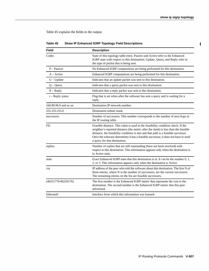
show ip eigrp topology
IP Routing Protocols Commands V-507
Table 45 explains the fields in the output.
Table 45 Show IP Enhanced IGRP Topology Field Descriptions
Field Description
Codes State of this topology table entry. Passive and Active refer to the EnhancedIGRP state with respect to this destination; Update, Query, and Reply refer tothe type of packet that is being sent.
P – Passive No Enhanced IGRP computations are being performed for this destination.
A – Active Enhanced IGRP computations are being performed for this destination.
U – Update Indicates that an update packet was sent to this destination.
Q – Query Indicates that a query packet was sent to this destination.
R – Reply Indicates that a reply packet was sent to this destination.
r – Reply status Flag that is set when after the software has sent a query and is waiting for areply.
160.89.90.0 and so on Destination IP network number.
255.255.255.0 Destination subnet mask.
successors Number of successors. This number corresponds to the number of next hops inthe IP routing table.
FD Feasible distance. This value is used in the feasibility condition check. If theneighbor’s reported distance (the metric after the slash) is less than the feasibledistance, the feasibility condition is met and that path is a feasible successor.Once the software determines it has a feasible successor, it does not have to senda query for that destination.
replies Number of replies that are still outstanding (have not been received) withrespect to this destination. This information appears only when the destination isin Active state.
state Exact Enhanced IGRP state that this destination is in. It can be the number 0, 1,2, or 3. This information appears only when the destination is Active.
via IP address of the peer who told the software about this destination. The first N ofthese entries, where N is the number of successors, are the current successors.The remaining entries on the list are feasible successors.
(46251776/46226176) The first number is the Enhanced IGRP metric that represents the cost to thedestination. The second number is the Enhanced IGRP metric that this peeradvertised.
Ethernet0 Interface from which this information was learned.

V-508 Network Protocols Command Reference, Part 1
show ip eigrp traffic
show ip eigrp trafficTo display the number of Enhanced IGRP packets sent and received, use theshow ip eigrp trafficEXEC command.
show ip eigrp traffic [autonomous-system-number]
Syntax Description
Command ModeEXEC
Usage GuidelinesThis command first appeared in Cisco IOS Release 10.0.
Sample DisplayThe following is sample output from theshow ip eigrp traffic command:
Router# show ip eigrp traffic
IP-EIGRP Traffic Statistics for process 77 Hellos sent/received: 218/205 Updates sent/received: 7/23 Queries sent/received: 2/0 Replies sent/received: 0/2 Acks sent/received: 21/14
Table 46 describes the fields that might be shown in the display.
autonomous-system-number (Optional) Autonomous system number.
Table 46 Show IP Enhanced IGRP Traffic Field Descriptions
Field Description
process 77 Autonomous system number specified in theip router command.
Hellos sent/received Number of hello packets that were sent and received.
Updates sent/received Number of update packets that were sent and received.
Queries sent/received Number of query packets that were sent and received.
Replies sent/received Number of reply packets that were sent and received.
Acks sent/received Number of acknowledgment packets that were sent and received.
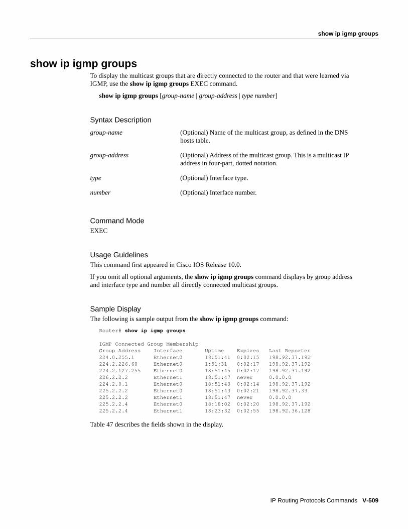
show ip igmp groups
IP Routing Protocols Commands V-509
show ip igmp groupsTo display the multicast groups that are directly connected to the router and that were learned viaIGMP, use theshow ip igmp groups EXEC command.
show ip igmp groups [group-name | group-address | type number]
Syntax Description
Command ModeEXEC
Usage GuidelinesThis command first appeared in Cisco IOS Release 10.0.
If you omit all optional arguments, theshow ip igmp groups command displays by group addressand interface type and number all directly connected multicast groups.
Sample DisplayThe following is sample output from theshow ip igmp groups command:
Router# show ip igmp groups
IGMP Connected Group MembershipGroup Address Interface Uptime Expires Last Reporter224.0.255.1 Ethernet0 18:51:41 0:02:15 198.92.37.192224.2.226.60 Ethernet0 1:51:31 0:02:17 198.92.37.192224.2.127.255 Ethernet0 18:51:45 0:02:17 198.92.37.192226.2.2.2 Ethernet1 18:51:47 never 0.0.0.0224.2.0.1 Ethernet0 18:51:43 0:02:14 198.92.37.192225.2.2.2 Ethernet0 18:51:43 0:02:21 198.92.37.33225.2.2.2 Ethernet1 18:51:47 never 0.0.0.0225.2.2.4 Ethernet0 18:18:02 0:02:20 198.92.37.192225.2.2.4 Ethernet1 18:23:32 0:02:55 198.92.36.128
Table 47 describes the fields shown in the display.
group-name (Optional) Name of the multicast group, as defined in the DNShosts table.
group-address (Optional) Address of the multicast group. This is a multicast IPaddress in four-part, dotted notation.
type (Optional) Interface type.
number (Optional) Interface number.

V-510 Network Protocols Command Reference, Part 1
show ip igmp groups
Related Commandip igmp query-interval
Table 47 Show IP IGMP Groups Field Descriptions
Field Description
Group address Address of the multicast group.
Interface Interface through which the group is reachable.
Uptime How long in hours, minutes, and seconds this multicast group hasbeen known.
Expires How long in hours, minutes, and seconds until the entry is removedfrom the IGMP groups table.
Last Reporter Last host to report being a member of the multicast group.

show ip igmp interface
IP Routing Protocols Commands V-511
show ip igmp interfaceTo display multicast-related information about an interface, use theshow ip igmp interface EXECcommand.
show ip igmp interface [type number]
Syntax Description
Command ModeEXEC
Usage GuidelinesThis command first appeared in Cisco IOS Release 10.0.
If you omit the optional arguments, theshow ip igmp interface command displays informationabout all interfaces.
This command also displays information about dynamically learned DVMRP routers on theinterface.
Sample DisplayThe following is sample output from theshow ip igmp interface command:
Router# show ip igmp interface
Ethernet0 is up, line protocol is up Internet address is 198.92.37.6, subnet mask is 255.255.255.0 IGMP is enabled on interface IGMP query interval is 60 seconds Inbound IGMP access group is not set Multicast routing is enabled on interface Multicast TTL threshold is 0 Multicast designated router (DR) is 198.92.37.33 No multicast groups joinedEthernet1 is up, line protocol is up Internet address is 198.92.36.129, subnet mask is 255.255.255.0 IGMP is enabled on interface IGMP query interval is 60 seconds Inbound IGMP access group is not set Multicast routing is enabled on interface Multicast TTL threshold is 0 Multicast designated router (DR) is 198.92.36.131 Multicast groups joined: 225.2.2.2 226.2.2.2Tunnel0 is up, line protocol is up Internet address is 10.1.37.2, subnet mask is 255.255.0.0 IGMP is enabled on interface IGMP query interval is 60 seconds Inbound IGMP access group is not set Multicast routing is enabled on interface Multicast TTL threshold is 0 No multicast groups joined
type (Optional) Interface type.
number (Optional) Interface number.

V-512 Network Protocols Command Reference, Part 1
show ip igmp interface
Table 48 describes the fields shown in the display.
Related Commandsip addressip igmp access-groupip igmp query-intervalip multicast ttl-thresholdip pim
Table 48 Show IP IGMP Interface Field Descriptions
Field Description
Ethernet0 is up, line protocol is up Interface type, number, and status.
Internet address is...subnet mask is...
Internet address of the interface and subnet mask being applied to theinterface, as specified with theip address command.
IGMP is enabled on interface Indicates whether IGMP has been enabled on the interface with theippim command.
IGMP query interval is 60 seconds Interval at which the Cisco IOS software sends PIM router-querymessages, as specified with theip igmp query-interval command.
Inbound IGMP access group is notset
Indicates whether an IGMP access group has been configured with theip igmp access-group command.
Multicast routing is enabled oninterface
Indicates whether multicast routing has been enabled on the interfacewith theip pim command.
Multicast TTL threshold is 0 Packet time-to-threshold, as specified with theip multicastttl-threshold command.
Multicast designated router (DR)is...
IP address of the designated router for this LAN segment (subnet).
Multicast groups joined:No multicast groups joined
Indicates whether this interface is a member of any multicast groupsand, if so, lists the IP addresses of the groups.
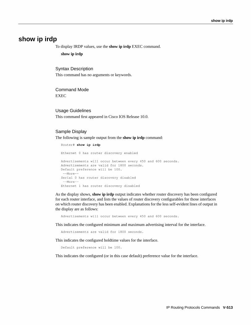
show ip irdp
IP Routing Protocols Commands V-513
show ip irdpTo display IRDP values, use theshow ip irdp EXEC command.
show ip irdp
Syntax DescriptionThis command has no arguments or keywords.
Command ModeEXEC
Usage GuidelinesThis command first appeared in Cisco IOS Release 10.0.
Sample DisplayThe following is sample output from theshow ip irdp command:
Router# show ip irdp
Ethernet 0 has router discovery enabled
Advertisements will occur between every 450 and 600 seconds.Advertisements are valid for 1800 seconds.Default preference will be 100. --More--Serial 0 has router discovery disabled --More--Ethernet 1 has router discovery disabled
As the display shows,show ip irdp output indicates whether router discovery has been configuredfor each router interface, and lists the values of router discovery configurables for those interfaceson which router discovery has been enabled. Explanations for the less self-evident lines of output inthe display are as follows:
Advertisements will occur between every 450 and 600 seconds.
This indicates the configured minimum and maximum advertising interval for the interface.
Advertisements are valid for 1800 seconds.
This indicates the configured holdtime values for the interface.
Default preference will be 100.
This indicates the configured (or in this case default) preference value for the interface.

V-514 Network Protocols Command Reference, Part 1
show ip local policy
show ip local policyTo display the route map used for local policy routing, if any, use theshow ip local policyEXECcommand.
show ip local policy
Syntax DescriptionThis command has no arguments or keywords.
Command ModeEXEC
Usage GuidelinesThis command first appeared in Cisco IOS Release 11.1.
Sample DisplayThe following is sample output from theshow ip local policycommand:
Router# show ip local policyLocal policy routing is enabled, using route map equalroute-map equal, permit, sequence 10 Match clauses: length 150 200 Set clauses: ip next-hop 10.10.11.254 Policy routing matches: 0 packets, 0 bytesroute-map equal, permit, sequence 20 Match clauses: ip address (access-lists): 101 Set clauses: ip next-hop 10.10.11.14 Policy routing matches: 2 packets, 172 bytes
Related Commandsip local policy route-mapmatch ip addressmatch lengthroute-mapset default interfaceset interfaceset ip default next-hopset ip next-hop

show ip mcache
IP Routing Protocols Commands V-515
show ip mcacheTo display the contents of the IP fast-switching cache, use theshow ip mcache EXEC command.
show ip mcache [group[source]]
Syntax Description
Command ModeEXEC
Usage GuidelinesThis command first appeared in Cisco IOS Release 11.0.
Sample DisplayThe following is sample output from theshow ip mcachecommand. This entry shows a specificsource (wrn-source 204.62.246.73) sending to the World Radio Network group (224.2.143.24).
Router> show ip mcache wrn wrn-source
IP Multicast Fast-Switching Cache(204.62.246.73/32, 224.2.143.24), Fddi0, Last used: 00:00:00 Ethernet0 MAC Header: 01005E028F1800000C1883D30800 Ethernet1 MAC Header: 01005E028F1800000C1883D60800 Ethernet2 MAC Header: 01005E028F1800000C1883D40800 Ethernet3 MAC Header: 01005E028F1800000C1883D70800
Table 49 describes the significant fields in the display.
group (Optional) Displays the fast-switching cache for the single group. Thegroupargument can be either a Class D IP address or a DNS name.
source (Optional) Ifsourceis also specified, displays a single multicast cache entry.Thesourceargument can be either a unicast IP address or a DNS name.
Table 49 Show IP Mcache Field Descriptions
Field Description
204.62.246.73 Source address.
224.2.143.24 Destination address.
Fddi0 Incoming or expected interface on which the packet should be received.
Last used: Latest time the entry was accessed for a packet that was successfully fast-switched. The word “Semi-fast” indicates that the first part of the outgoinginterface list is fast switched and the rest of the list is process levelswitched.
Ethernet0
MAC Header:
Outgoing interface list and respective MAC header that is used whenrewriting the packet for output. If the interface is a tunnel, the MAC headerwill show the real next hop MAC header and then, in parentheses, the realinterface name.

V-516 Network Protocols Command Reference, Part 1
show ip mroute
show ip mrouteTo display the contents of the IP multicast routing table, use theshow ip mroute EXEC command.
show ip mroute [group-name| group-address] [source] [summary] [count] activekbps
Syntax Description
DefaultShows all sources sending at a rate greater than or equal to 1 kbps.
Command ModeEXEC
Usage GuidelinesThis command first appeared in Cisco IOS Release 10.0.
If you omit all optional arguments and keywords, theshow ip mroute command displays all entriesin the IP multicast routing table.
The Cisco IOS software populates the multicast routing table by creating source, group (S,G) entriesfrom star, group (*,G) entries. The star refers to all source addresses, the “S” refers to a single sourceaddress, and the “G” is the destination multicast group address. In creating (S,G) entries, thesoftware uses the best path to that destination group found in the unicast routing table (that is, viaReverse Path Forwarding [RPF]).
group-name|group-address
(Optional) IP address, name, or interface of the multicast group asdefined in the DNS hosts table.
source (Optional) IP address or name of a multicast source.
summary (Optional) Displays a one-line, abbreviated summary of each entry in theIP multicast routing table.
count (Optional) Displays statistics about the group and source, includingnumber of packets, packets per second, average packet size, and bits persecond.
active (Optional) Displays rate active sources are sending to multicast groups.
kbps (Optional) Displays sources that are sending overn kbps.

show ip mroute
IP Routing Protocols Commands V-517
Sample DisplaysThe following is sample output from theshow ip mroute command for a router operating is densemode. This command displays the contents of the IP multicast routing table for the multicast groupnamed cbone-audio.
Router> show ip mroute cbone-audio
IP Multicast Routing TableFlags: D - Dense, S - Sparse, C - Connected, L - Local, P - Pruned
R - RP-bit set, F - Register flag, T - SPT-bit setTimers: Uptime/ExpiresInterface state: Interface, Next-Hop, State/Mode
(*, 224.0.255.1), uptime 0:57:31, expires 0:02:59, RP is 0.0.0.0, flags: DC Incoming interface: Null, RPF neighbor 0.0.0.0, Dvmrp Outgoing interface list: Ethernet0, Forward/Dense, 0:57:31/0:02:52 Tunnel0, Forward/Dense, 0:56:55/0:01:28
(198.92.37.100/32, 224.0.255.1), uptime 20:20:00, expires 0:02:55, flags: C Incoming interface: Tunnel0, RPF neighbor 10.20.37.33, Dvmrp Outgoing interface list: Ethernet0, Forward/Dense, 20:20:00/0:02:52
The following is sample output from theshow ip mroute command for a router operating in sparsemode:
Router# show ip mroute
IP Multicast Routing TableFlags: D - Dense, S - Sparse, C - Connected, L - Local, P - Pruned
R - RP-bit set, F - Register flag, T - SPT-bit setTimers: Uptime/ExpiresInterface state: Interface, Next-Hop, State/Mode
(*, 224.0.255.3), uptime 5:29:15, RP is 198.92.37.2, flags: SC Incoming interface: Tunnel0, RPF neighbor 10.3.35.1, Dvmrp Outgoing interface list: Ethernet0, Forward/Sparse, 5:29:15/0:02:57
(198.92.46.0/24, 224.0.255.3), uptime 5:29:15, expires 0:02:59, flags: C Incoming interface: Tunnel0, RPF neighbor 10.3.35.1 Outgoing interface list: Ethernet0, Forward/Sparse, 5:29:15/0:02:57
Table 50 explains the fields shown in the displays.
Table 50 Show IP Mroute Field Descriptions
Field Description
Flags: Provides information about the entry.
D - Dense Entry is operating in dense mode.
S - Sparse Entry is operating in sparse mode.
C - Connected A member of the multicast group is present on the directly connectedinterface.
L - Local The router itself is a member of the multicast group.
P - Pruned Route has been pruned. The Cisco IOS software keeps thisinformation in case a downstream member wants to join the source.

V-518 Network Protocols Command Reference, Part 1
show ip mroute
Related Commandip igmp query-interval
R - Rp-bit set Indicates that the (S,G) entry is pointing towards the RP. This istypically prune state along the shared tree for a particular source.
F - Register flag Indicates that the software is Registering for a multicast source.
T - SPT-bit set Indicates that packets have been received on the shortest path sourcetree.
(*, 224.0.255.1)(198.92.37.100/32, 224.0.255.1)
Entry in the IP multicast routing table. The entry consists of the IPaddress of the source router followed by IP address of the multicastgroup. An asterisk (*) in place of the source router indicates allsources.
Entries in the first format are referred to as (*,G,) or “star comma G,”entries. Entries in the second format are referred to as (S,G) or(“S comma G”) entries. (*,G) entries are used to build (S,G) entries.
uptime How long in hours, minutes, and seconds the entry has been in the IPmulticast routing table.
expires How long in hours, minutes, and seconds until the entry will beremoved from the IP multicast routing table on the outgoing interface.
RP Address of the rendezvous point (RP) router. For routers and accessservers operating in sparse mode, this address is always 0.0.0.0.
flags: Information about the entry.
Incoming interface: Expected interface for a multicast packet from the source. If thepacket is not received on this interface, it is discarded.
RPF neighbor IP address of the upstream router to the source. “Tunneling” indicatesthat this router is sending data to the RP encapsulated in Registerpackets. The hexadecimal number in parentheses indicates to whichRP we are registering. Each bit indicates a different RP if multipleRPs per group are used.
Dvmrp or Mroute Indicates if the RPF information is obtained from the DVMRP routingtable or the static mroutes configuration.
Outgoing interface list: Interfaces through which packets will be forwarded. When theinterface hasip pim nbma-mode, the IP address of the PIM neighboris also displayed.
Ethernet0 Name and number of the outgoing interface.
Forward/Dense Indicates that packets will be forwarded on the interface if there are norestrictions due to access lists or TTL threshold. Following the slash,mode in which the interface is operating (dense or sparse).
time/time How long in hours, minutes, and seconds the entry has been in the IPmulticast routing table. Following the slash, how long in hours,minutes, and seconds until the entry will be removed from the IPmulticast routing table.
Table 50 Show IP Mroute Field Descriptions (Continued)
Field Description

show ip ospf
IP Routing Protocols Commands V-519
show ip ospfTo display general information about OSPF routing processes, use theshow ip ospf EXECcommand.
show ip ospf[process-id]
Syntax Description
Command ModeEXEC
Usage GuidelinesThis command first appeared in Cisco IOS Release 10.0.
Sample DisplayThe following is sample output from theshow ip ospf command when entered without a specificOSPF process ID:
Router# show ip ospf
Routing Process "ospf 201" with ID 192.42.110.200Supports only single TOS(TOS0) routeIt is an area border and autonomous system boundary routerSummary Link update interval is 0:30:00 and the update due in 0:16:26External Link update interval is 0:30:00 and the update due in 0:16:27Redistributing External Routes from,
igrp 200 with metric mapped to 2, includes subnets in redistributionrip with metric mapped to 2igrp 2 with metric mapped to 100igrp 32 with metric mapped to 1
Number of areas in this router is 3Area 192.42.110.0
Number of interfaces in this area is 1Area has simple password authenticationSPF algorithm executed 6 timesArea ranges areLink State Update Interval is 0:30:00 and due in 0:16:55Link State Age Interval is 0:20:00 and due in 0:06:55
process-id (Optional) Process ID. If this argument is included, onlyinformation for the specified routing process is included.

V-520 Network Protocols Command Reference, Part 1
show ip ospf
Table 51 describes significant fields shown in the display.
Table 51 Show IP OSPF Field Descriptions
Field Description
Routing process “ospf 201” with ID192.42.110.200
Process ID and OSPF router ID.
Type of service Number of Types of service supported (Type 0 only).
Type of OSPF Router Possible types are internal, area border, or autonomous systemboundary.
Summary Link update interval Specify summary update interval in hours:minutes:seconds, andtime to next update.
External Link update interval Specify external update interval in hours:minutes:seconds, andtime to next update.
Redistributing External Routes from Lists of redistributed routes, by protocol.
Number of areas Number of areas in router, area addresses, and so on.
Link State Update Interval Specify router and network link state update interval inhours:minutes:seconds, and time to next update.
Link State Age Interval Specify max-aged update deletion interval and time until nextdatabase cleanup in hours:minutes:seconds.

show ip ospf border-routers
IP Routing Protocols Commands V-521
show ip ospf border-routersTo display the internal OSPF routing table entries to an area border router (ABR) and autonomoussystem boundary router (ASBR), use theshow ip ospf border-routers privileged EXEC command.
show ip ospf border-routers
Syntax DescriptionThis command has no arguments or keywords.
Command ModePrivileged EXEC
Usage GuidelinesThis command first appeared in Cisco IOS Release 10.0.
Sample DisplayThe following is sample output from theshow ip ospf border-routers command:
Router# show ip ospf border-routers
OSPF Process 109 internal Routing Table
Destination Next Hop Cost Type Rte Type Area SPF No
160.89.97.53 144.144.1.53 10 ABR INTRA 0.0.0.3 3160.89.103.51 160.89.96.51 10 ABR INTRA 0.0.0.3 3160.89.103.52 160.89.96.51 20 ASBR INTER 0.0.0.3 3160.89.103.52 144.144.1.53 22 ASBR INTER 0.0.0.3 3
Table 52 describes the fields shown in the display.
Table 52 Show IP OSPF Border-Routers Field Descriptions
Field Description
Destination Destination’s router ID.
Next Hop Next hop toward the destination.
Cost Cost of using this route.
Type The router type of the destination; it is either an area border router(ABR) or autonomous system boundary router (ASBR) or both.
Rte Type The type of this route, it is either an intra-area or interarea route.
Area The area ID of the area that this route is learned from.
SPF No The internal number of SPF calculation that installs this route.

V-522 Network Protocols Command Reference, Part 1
show ip ospf database
show ip ospf databaseUse theshowip ospf database EXEC command to display lists of information related to the OSPFdatabase for a specific router. The various forms of this command deliver information about differentOSPF link state advertisements.
show ip ospf[process-id area-id] databaseshow ip ospf[process-id area-id] database[router ] [ link-state-id]show ip ospf[process-id area-id] database[network] [ link-state-id]show ip ospf[process-id area-id] database[summary] [ link-state-id]show ip ospf[process-id area-id] database[asb-summary] [ link-state-id]show ip ospf[process-id area-id] database[nssa-external] [ link-state-id]show ip ospf[process-id] database[external] [ link-state-id]show ip ospf[process-id area-id] database[database-summary]
Syntax Description
When entered with the optional keywordrouter, network, summary, asb-summary, external, ordatabase-summary, different displays result. Examples and brief descriptions of each form follow.
Command ModeEXEC
process-id (Optional) Internally used identification parameter. It islocally assigned and can be any positive integer number.The number used here is the number assignedadministratively when enabling the OSPF routing process.
area-id (Optional) Area number associated with the OSPF addressrange defined in thenetwork router configurationcommand used to define the particular area.
link-state-id (Optional) Identifies the portion of the Internetenvironment that is being described by the advertisement.The value entered depends on the advertisement’s LS type.It must be entered in the form of an IP address.
When the link state advertisement is describing a network,the link-state-id can take one of two forms:
—The network’s IP address (as in type 3 summary linkadvertisements and in autonomous system external linkadvertisements).
—A derived address obtained from the link state ID. (Notethat masking a network links advertisement’s link state IDwith the network’s subnet mask yields the network’s IPaddress.)
When the link state advertisement is describing a router,the link state ID is always the described router’s OSPFrouter ID.
When an autonomous system external advertisement(LS Type = 5) is describing a default route, its link state IDis set to Default Destination (0.0.0.0).

show ip ospf database
IP Routing Protocols Commands V-523
Usage GuidelinesThis command first appeared in Cisco IOS Release 10.0. The following form of the command firstappeared in Cisco IOS Release 11.0:
show ip ospf[process-id area-id] database[database-summary].
Sample Display of Show IP OSPF Database with No Arguments or KeywordsThe following is sample output from theshow ip ospf database command when no arguments orkeywords are used:
Router# show ip ospf database
OSPF Router with id(190.20.239.66) (Autonomous system 300)
Displaying Router Link States(Area 0.0.0.0)
Link ID ADV Router Age Seq# Checksum Link count155.187.21.6 155.187.21.6 1731 0x80002CFB 0x69BC 8155.187.21.5 155.187.21.5 1112 0x800009D2 0xA2B8 5155.187.1.2 155.187.1.2 1662 0x80000A98 0x4CB6 9155.187.1.1 155.187.1.1 1115 0x800009B6 0x5F2C 1155.187.1.5 155.187.1.5 1691 0x80002BC 0x2A1A 5155.187.65.6 155.187.65.6 1395 0x80001947 0xEEE1 4155.187.241.5 155.187.241.5 1161 0x8000007C 0x7C70 1155.187.27.6 155.187.27.6 1723 0x80000548 0x8641 4155.187.70.6 155.187.70.6 1485 0x80000B97 0xEB84 6
Displaying Net Link States(Area 0.0.0.0)
Link ID ADV Router Age Seq# Checksum155.187.1.3 192.20.239.66 1245 0x800000EC 0x82E
Displaying Summary Net Link States(Area 0.0.0.0)
Link ID ADV Router Age Seq# Checksum155.187.240.0 155.187.241.5 1152 0x80000077 0x7A05155.187.241.0 155.187.241.5 1152 0x80000070 0xAEB7155.187.244.0 155.187.241.5 1152 0x80000071 0x95CB
Table 53 describes significant fields shown in the display.
Table 53 Show IP OSPF Database Field Descriptions
Field Description
Link ID Router ID number.
ADV Router Advertising router’s ID.
Age Link state age.
Seq# Link state sequence number (detects old or duplicate link state advertisements).
Checksum Fletcher checksum of the complete contents of the link state advertisement.
Link count Number of interfaces detected for router.

V-524 Network Protocols Command Reference, Part 1
show ip ospf database
Sample Display Using Show IP OSPF Database ASB-SummaryThe following is sample output from theshow ip ospf database asb-summary command when nooptional arguments are specified:
Router# show ip ospf database asb-summary
OSPF Router with id(190.20.239.66) (Autonomous system 300)
Displaying Summary ASB Link States(Area 0.0.0.0)
LS age: 1463Options: (No TOS-capability)LS Type: Summary Links(AS Boundary Router)Link State ID: 155.187.245.1 (AS Boundary Router address)Advertising Router: 155.187.241.5LS Seq Number: 80000072Checksum: 0x3548Length: 28Network Mask: 0.0.0.0 TOS: 0 Metric: 1
Table 54 describes significant fields shown in the display.
Table 54 Show IP OSPF Database ASB-Summary Field Descriptions
Field Description
Router ID Router ID number.
Autonomous system OSPF autonomous system number (OSPF process ID).
LS age Link state age.
Options Type of service options (Type 0 only).
LS Type Link state type.
Link State ID Link state ID (autonomous system boundary router).
Advertising Router Advertising router’s ID.
LS Seq Number Link state sequence (detects old or duplicate link state advertisements).
Checksum LS checksum (Fletcher checksum of the complete contents of the link stateadvertisement).
Length Length in bytes of the link state advertisement.
Network Mask Network mask implemented.
TOS Type of service.
Metric Link state metric.
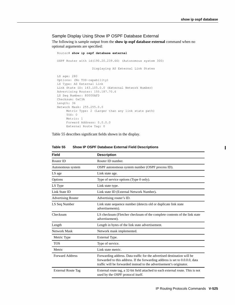
show ip ospf database
IP Routing Protocols Commands V-525
Sample Display Using Show IP OSPF Database ExternalThe following is sample output from theshow ip ospf database external command when nooptional arguments are specified:
Router# show ip ospf database external
OSPF Router with id(190.20.239.66) (Autonomous system 300)
Displaying AS External Link States
LS age: 280Options: (No TOS-capability)LS Type: AS External LinkLink State ID: 143.105.0.0 (External Network Number)Advertising Router: 155.187.70.6LS Seq Number: 80000AFDChecksum: 0xC3ALength: 36Network Mask: 255.255.0.0
Metric Type: 2 (Larger than any link state path)TOS: 0Metric: 1Forward Address: 0.0.0.0External Route Tag: 0
Table 55 describes significant fields shown in the display.
Table 55 Show IP OSPF Database External Field Descriptions
Field Description
Router ID Router ID number.
Autonomous system OSPF autonomous system number (OSPF process ID).
LS age Link state age.
Options Type of service options (Type 0 only).
LS Type Link state type.
Link State ID Link state ID (External Network Number).
Advertising Router Advertising router’s ID.
LS Seq Number Link state sequence number (detects old or duplicate link stateadvertisements).
Checksum LS checksum (Fletcher checksum of the complete contents of the link stateadvertisement).
Length Length in bytes of the link state advertisement.
Network Mask Network mask implemented.
Metric Type External Type.
TOS Type of service.
Metric Link state metric.
Forward Address Forwarding address. Data traffic for the advertised destination will beforwarded to this address. If the forwarding address is set to 0.0.0.0, datatraffic will be forwarded instead to the advertisement’s originator.
External Route Tag External route tag, a 32-bit field attached to each external route. This is notused by the OSPF protocol itself.

V-526 Network Protocols Command Reference, Part 1
show ip ospf database
Sample Display Using Show IP OSPF Database NetworkThe following is sample output from theshow ip ospf database network command when nooptional arguments are specified:
Router# show ip ospf database network OSPF Router with id(190.20.239.66) (Autonomous system 300)
Displaying Net Link States(Area 0.0.0.0)
LS age: 1367Options: (No TOS-capability)LS Type: Network LinksLink State ID: 155.187.1.3 (address of Designated Router)Advertising Router: 190.20.239.66LS Seq Number: 800000E7Checksum: 0x1229Length: 52Network Mask: 255.255.255.0 Attached Router: 190.20.239.66 Attached Router: 155.187.241.5 Attached Router: 155.187.1.1 Attached Router: 155.187.54.5 Attached Router: 155.187.1.5
Table 56 describes significant fields shown in the display.
Table 56 Show IP OSPF Database Network Field Descriptions
Field Description
OSPF Router with ID Router ID number.
Autonomous system 300 OSPF autonomous system number (OSPF process ID).
LS age: Link state age.
Options: Type of service options (Type 0 only).
LS Type: Link state type.
Link State ID Link state ID of designated router.
Advertising Router Advertising router’s ID.
LS Seq Number Link state sequence (detects old or duplicate link stateadvertisements).
Checksum LS checksum (Fletcher checksum of the complete contents of thelink state advertisement).
Network Mask Network mask implemented.
AS Boundary Router Definition of router type.
Attached Router List of routers attached to the network, by IP address.

show ip ospf database
IP Routing Protocols Commands V-527
Sample Display Using Show IP OSPF Database RouterThe following is sample output from theshow ip ospf database router command when no optionalarguments are specified:
Router# show ip ospf database router
OSPF Router with id(190.20.239.66) (Autonomous system 300)
Displaying Router Link States(Area 0.0.0.0)
LS age: 1176Options: (No TOS-capability)LS Type: Router LinksLink State ID: 155.187.21.6Advertising Router: 155.187.21.6LS Seq Number: 80002CF6Checksum: 0x73B7Length: 120AS Boundary Router155 Number of Links: 8
Link connected to: another Router (point-to-point)(link ID) Neighboring Router ID: 155.187.21.5(Link Data) Router Interface address: 155.187.21.6Number of TOS metrics: 0TOS 0 Metrics: 2
Table 57 describes significant fields shown in the display.
Table 57 Show IP OSPF Database Router Field Descriptions
Field Description
OSPF Router with ID Router ID number.
Autonomous system OSPF autonomous system number (OSPF process ID).
LS age Link state age.
Options Type of service options (Type 0 only).
LS Type Link state type.
Link State ID Link state ID.
Advertising Router Advertising router’s ID.
LS Seq Number Link state sequence (detects old or duplicate link state advertisements).
Checksum LS checksum (Fletcher checksum of the complete contents of the link stateadvertisement).
Length Length in bytes of the link state advertisement.
AS Boundary Router Definition of router type.
Number of Links Number of active links.
link ID Link type.
Link Data Router interface address.
TOS Type of service metric (Type 0 only).

V-528 Network Protocols Command Reference, Part 1
show ip ospf database
Sample Display Using Show IP OSPF Database SummaryThe following is sample output fromshow ip ospf database summary command when no optionalarguments are specified:
Router# show ip ospf database summary
OSPF Router with id(190.20.239.66) (Autonomous system 300)
Displaying Summary Net Link States(Area 0.0.0.0)
LS age: 1401Options: (No TOS-capability)LS Type: Summary Links(Network)Link State ID: 155.187.240.0 (summary Network Number)Advertising Router: 155.187.241.5LS Seq Number: 80000072Checksum: 0x84FFLength: 28Network Mask: 255.255.255.0 TOS: 0 Metric: 1
Table 58 describes significant fields shown in the display.
Sample Display Using Show IP OSPF Database Database-SummaryThe following is sample output fromshow ip ospf database database-summary command whenno optional arguments are specified:
Router# show ip ospf database database-summary
OSPF Router with ID (172.19.65.21) (Process ID 1)
Area ID Router Network Sum-Net Sum-ASBR Subtotal Delete Maxage202 1 0 0 0 1 0 0AS External 0 0 0Total 1 0 0 0 1
Table 58 Show IP OSPF Database Summary Field Descriptions
Field Description
OSPF Router with ID Router ID number.
Autonomous system OSPF autonomous system number (OSPF process ID).
LS age Link state age.
Options Type of service options (Type 0 only).
LS Type Link state type.
Link State ID Link state ID (summary network number).
Advertising Router Advertising router’s ID.
LS Seq Number Link state sequence (detects old or duplicate link state advertisements).
Checksum LS checksum (Fletcher checksum of the complete contents of the link stateadvertisement).
Length Length in bytes of the link state advertisement.
Network Mask Network mask implemented.
TOS Type of service.
Metric Link state metric.
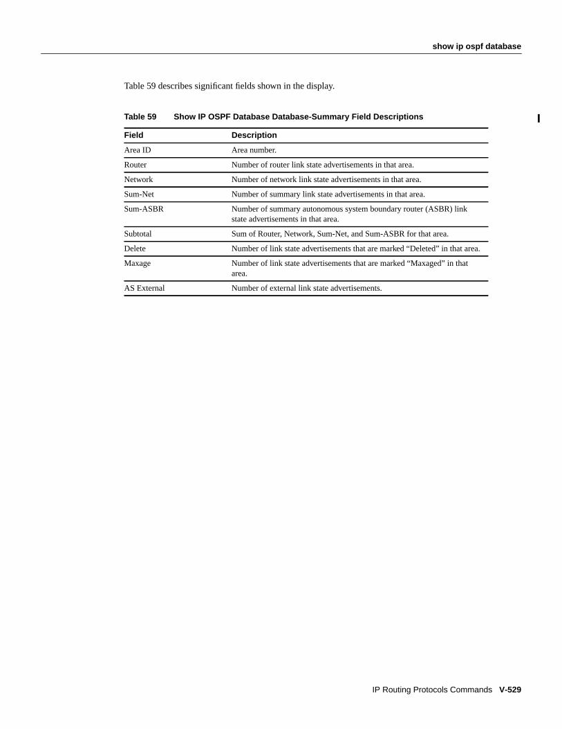
show ip ospf database
IP Routing Protocols Commands V-529
Table 59 describes significant fields shown in the display.
Table 59 Show IP OSPF Database Database-Summary Field Descriptions
Field Description
Area ID Area number.
Router Number of router link state advertisements in that area.
Network Number of network link state advertisements in that area.
Sum-Net Number of summary link state advertisements in that area.
Sum-ASBR Number of summary autonomous system boundary router (ASBR) linkstate advertisements in that area.
Subtotal Sum of Router, Network, Sum-Net, and Sum-ASBR for that area.
Delete Number of link state advertisements that are marked “Deleted” in that area.
Maxage Number of link state advertisements that are marked “Maxaged” in thatarea.
AS External Number of external link state advertisements.

V-530 Network Protocols Command Reference, Part 1
show ip ospf interface
show ip ospf interfaceTo display OSPF-related interface information, use theshow ip ospf interface EXEC command.
show ip ospf interface[type number]
Syntax Description
Command ModeEXEC
Usage GuidelinesThis command first appeared in Cisco IOS Release 10.0.
Sample DisplayThe following is sample output from theshow ip ospf interface command when Ethernet 0 isspecified:
Router# show ip ospf interface ethernet 0
Ethernet 0 is up, line protocol is upInternet Address 131.119.254.202, Mask 255.255.255.0, Area 0.0.0.0AS 201, Router ID 192.77.99.1, Network Type BROADCAST, Cost: 10Transmit Delay is 1 sec, State OTHER, Priority 1Designated Router id 131.119.254.10, Interface address 131.119.254.10Backup Designated router id 131.119.254.28, Interface addr 131.119.254.28Timer intervals configured, Hello 10, Dead 60, Wait 40, Retransmit 5Hello due in 0:00:05Neighbor Count is 8, Adjacent neighbor count is 2
Adjacent with neighbor 131.119.254.28 (Backup Designated Router)Adjacent with neighbor 131.119.254.10 (Designated Router)
Table 60 describes significant fields shown in the display.
type (Optional) Interface type.
number (Optional) Interface number.

show ip ospf interface
IP Routing Protocols Commands V-531
Table 60 Show IP OSPF Interface Ethernet 0 Field Descriptions
Field Description
Ethernet Status of physical link and operational status of protocol.
Internet Address Interface IP address, subnet mask, and area address.
AS Autonomous system number (OSPF process ID), router ID, networktype, link state cost.
Transmit Delay Transmit delay, interface state, and router priority.
Designated Router Designated router ID and respective interface IP address.
Backup Designated router Backup designated router ID and respective interface IP address.
Timer intervals configured Configuration of timer intervals.
Hello Number of seconds until next hello packet is sent out this interface.
Neighbor Count Count of network neighbors and list of adjacent neighbors.

V-532 Network Protocols Command Reference, Part 1
show ip ospf neighbor
show ip ospf neighborTo display OSPF-neighbor information on a per-interface basis, use theshow ip ospf neighborEXEC command.
show ip ospf neighbor[type number] [neighbor-id] detail
Syntax Description
Command ModeEXEC
Usage GuidelinesThis command first appeared in Cisco IOS Release 10.0.
Sample DisplaysThe following is sample output from the show ip ospf neighbor command showing a single line ofsummary information for each neighbor:
Router# show ip ospf neighbor
ID Pri State Dead Time Address Interface199.199.199.137 1 FULL/DR 0:00:31 160.89.80.37 Ethernet0192.31.48.1 1 FULL/DROTHER 0:00:33 192.31.48.1 Fddi0192.31.48.200 1 FULL/DROTHER 0:00:33 192.31.48.200 Fddi0199.199.199.137 5 FULL/DR 0:00:33 192.31.48.189 Fddi0
The following is sample output showing summary information about the neighbor that matches theneighbor ID:
Router# show ip ospf neighbor 199.199.199.137
Neighbor 199.199.199.137, interface address 160.89.80.37 In the area 0.0.0.0 via interface Ethernet0 Neighbor priority is 1, State is FULL Options 2 Dead timer due in 0:00:32 Link State retransmission due in 0:00:04 Neighbor 199.199.199.137, interface address 192.31.48.189 In the area 0.0.0.0 via interface Fddi0 Neighbor priority is 5, State is FULL Options 2 Dead timer due in 0:00:32 Link State retransmission due in 0:00:03
type (Optional) Interface type.
number (Optional) Interface number.
neighbor-id (Optional) Neighbor ID.
detail Displays all neighbors given in detail (list all neighbors).

show ip ospf neighbor
IP Routing Protocols Commands V-533
If you specify the interface along with the Neighbor ID, the Cisco IOS software displays theneighbors that match the neighbor ID on the interface, as in the following sample display:
Router# show ip ospf neighbor e 0 199.199.199.137
Neighbor 199.199.199.137, interface address 160.89.80.37 In the area 0.0.0.0 via interface Ethernet0 Neighbor priority is 1, State is FULL Options 2 Dead timer due in 0:00:37 Link State retransmission due in 0:00:04
You can also specify the interface without the neighbor ID to show all neighbors on the specifiedinterface, as in the following sample display:
Router# show ip ospf neighbor f 0
ID Pri State Dead Time Address Interface192.31.48.1 1 FULL/DROTHER 0:00:33 192.31.48.1 Fddi0192.31.48.200 1 FULL/DROTHER 0:00:32 192.31.48.200 Fddi0199.199.199.137 5 FULL/DR 0:00:32 192.31.48.189 Fddi0
The following is sample output from the show ip ospf neighbor detail command:
Router# show ip ospf neighbor detail
Neighbor 160.89.96.54, interface address 160.89.96.54 In the area 0.0.0.3 via interface Ethernet0 Neighbor priority is 1, State is FULL Options 2 Dead timer due in 0:00:38 Neighbor 160.89.103.52, interface address 160.89.103.52 In the area 0.0.0.0 via interface Serial0 Neighbor priority is 1, State is FULL Options 2 Dead timer due in 0:00:31
Table 61 describes the fields shown in the displays.
Table 61 Show IP OSPF Neighbor Field Descriptions
Field Description
Neighbor x.x.x.x Neighbor router ID.
interface address x.x.x.x IP address of the interface.
In the area Area and interface through which OSPF neighbor is known.
Neighbor priority Router priority of neighbor, neighbor state.
State OSPF state.
Options Hello packet options field contents (E-bit only; possible values are 0and 2; 2 indicates area is not a stub; 0 indicates area is a stub.
Dead timer Expected time before Cisco IOS software will declare neighbor dead.

V-534 Network Protocols Command Reference, Part 1
show ip ospf virtual-links
show ip ospf virtual-linksTo display parameters about and the current state of OSPF virtual links, use theshow ip ospfvirtual-links EXEC command.
show ip ospf virtual-links
Syntax DescriptionThis command has no arguments or keywords.
Command ModeEXEC
Usage GuidelinesThis command first appeared in Cisco IOS Release 10.0.
The information displayed byshow ip ospf virtual-links is useful in debugging OSPF routingoperations.
Sample DisplayThe following is sample output from theshow ip ospf virtual-links command:
Router# show ip ospf virtual-links
Virtual Link to router 160.89.101.2 is upTransit area 0.0.0.1, via interface Ethernet0, Cost of using 10Transmit Delay is 1 sec, State POINT_TO_POINTTimer intervals configured, Hello 10, Dead 40, Wait 40, Retransmit 5Hello due in 0:00:08Adjacency State FULL
Table 62 describes significant fields shown in the display.
Table 62 Show IP OSPF Virtual-Links Field Descriptions
Field Description
Virtual Link to router 160.89.101.2is Up
Specifies the OSPF neighbor, and if the link to that neighbor is Up orDown.
Transit area 0.0.0.1 The transit area through which the virtual link is formed.
via interface Ethernet0 The interface through which the virtual link is formed.
Cost of using 10 The cost of reaching the OSPF neighbor through the virtual link.
Transmit Delay is 1 sec The transmit delay on the virtual link.
State POINT_TO_POINT The state of the OSPF neighbor.
Timer intervals... The various timer intervals configured for the link.
Hello due in 0:00:08 When the next hello is expected from the neighbor.
Adjacency State FULL The adjacency state between the neighbors.

show ip pim interface
IP Routing Protocols Commands V-535
show ip pim interfaceTo display information about interfaces configured for PIM, use theshow ip pim interface EXECcommand.
show ip pim interface[type number]
Syntax Description
Command ModeEXEC
Usage GuidelinesThis command first appeared in Cisco IOS Release 10.0.
This command works only on interfaces that are configured for PIM.
Sample DisplayThe following is sample output from theshow ip pim interface command:
Router# show ip pim interface
Address Interface Mode Neighbor Query DR Count Interval198.92.37.6 Ethernet0 Dense 2 30 198.92.37.33198.92.36.129 Ethernet1 Dense 2 30 198.92.36.13110.1.37.2 Tunnel0 Dense 1 30 0.0.0.0
Table 63 describes the fields shown in the display.
type (Optional) Interface type.
number (Optional) Interface number.
Table 63 Show IP PIM Interface Field Descriptions
Field Description
Address IP address of the next-hop router.
Interface Interface type and number that is configured to run PIM.
Mode Multicast mode in which the Cisco IOS software is operating. This can be densemode or sparse mode. DVMRP indicates a DVMRP tunnel is configured.
Neighbor Count Number of PIM neighbors that have been discovered through this interface. Ifthe Neighbor Count is 1 for a DVMRP tunnel, the neighbor is active (receivingprobes and reports).
Query Interval Frequency, in seconds, of PIM router-query messages, as set by theip pimquery-interval interface configuration command. The default is 30 seconds.
DR IP address of the designated router on the LAN. Note that serial lines do nothave designated routers, so the IP address is shown as 0.0.0.0.

V-536 Network Protocols Command Reference, Part 1
show ip pim interface
Related Commandsip pimshow ip pim neighbor

show ip pim neighbor
IP Routing Protocols Commands V-537
show ip pim neighborTo list the PIM neighbors discovered by the Cisco IOS software, use theshow ip pim neighborEXEC command.
show ip pim neighbor[type number]
Syntax Description
Command ModeEXEC
Usage GuidelinesThis command first appeared in Cisco IOS Release 10.0.
Use this command to determine which routers on the LAN are configured for PIM.
Sample DisplayThe following is sample output from theshow ip pim neighbor command:
Router# show ip pim neighbor
PIM Neighbor TableNeighbor Address Interface Uptime Expires Mode198.92.37.2 Ethernet0 17:38:16 0:01:25 Dense198.92.37.33 Ethernet0 17:33:20 0:01:05 Dense (DR)198.92.36.131 Ethernet1 17:33:20 0:01:08 Dense (DR)198.92.36.130 Ethernet1 18:56:06 0:01:04 Dense10.1.22.9 Tunnel0 19:14:59 0:01:09 Dense
Table 64 describes the fields shown in the display.
type (Optional) Interface type.
number (Optional) Interface number.
Table 64 Show IP PIM Neighbor Field Descriptions
Field Description
Neighbor Address IP address of the PIM neighbor.
Interface Interface type and number on which the neighbor is reachable.
Uptime How long in hours, minutes, and seconds the entry has been in the PIMneighbor table.
Expires How long in hours, minutes, and seconds until the entry will be removed fromthe IP multicast routing table.
Mode Mode in which the interface is operating.
(DR) Indicates that this neighbor is a designated router on the LAN.

V-538 Network Protocols Command Reference, Part 1
show ip pim neighbor
Related Commandshow ip pim interface

show ip pim rp
IP Routing Protocols Commands V-539
show ip pim rpTo display the rendezvous point (RP) routers associated with a sparse-mode multicast group, use theshow ip pim rp EXEC command.
show ip pim rp [group-name | group-address]
Syntax Description
Command ModeEXEC
Usage GuidelinesThis command first appeared in Cisco IOS Release 10.0.
Sample DisplaysThe following is sample output from theshow ip pim rp command from a router that is not an RP:
Router1# show ip pim rp
Group: 224.2.127.255, number of RPs: 1 RP address: 198.92.37.2, state: Up, uptime 0:01:25, expires in 0:03:04
The following is sample output from theshow ip pim rp command from a router that is an RP:
Router2# show ip pim rp
Group: 224.2.127.255, number of RPs: 1 RP address: 198.92.37.2, state: Up, next RP-reachable in 0:01:01
Table 65 describes the fields shown in the displays.
group-name (Optional) Name of the multicast group, as defined in the DNShosts table.
group-address (Optional) Address of the multicast group. This is a multicast IPaddress in four-part, dotted notation.
Table 65 Show IP PIM RP Field Descriptions
Field Description
Group: Address of the multicast group.
number of RPs: Number of RPs in the multicast group.
RP address: Address of the RP.
state: State of the RP router; it can be Up or Down.
uptime How long in hours, minutes, and seconds the RP has been up.
expires How long in hours, minutes, and seconds until the entry for this RPexpires.
next RP-reachable in How long in hours, minutes, and seconds until the RP will send itsnext RP-reachable message.

V-540 Network Protocols Command Reference, Part 1
show ip pim rp
Related Commandshow ip mroute

show ip policy
IP Routing Protocols Commands V-541
show ip policyTo display the route map used for policy routing, use theshow ip policyEXEC command.
show ip policy
Syntax DescriptionThis command has no arguments or keywords.
Command ModeEXEC
Usage GuidelinesThis command first appeared in Cisco IOS Release 11.1.
Sample DisplaysThe following is sample output from theshow ip policycommand:
Router# show ip policyInterface Route maplocal equalEthernet0 equal
The following is sample output from theshow route-mapcommand, which relates to the precedingsample display:
Router# show route-maproute-map equal, permit, sequence 10 Match clauses: length 150 200 Set clauses: ip next-hop 10.10.11.254 Policy routing matches: 0 packets, 0 bytesroute-map equal, permit, sequence 20 Match clauses: ip address (access-lists): 101 Set clauses: ip next-hop 10.10.11.14 Policy routing matches: 144 packets, 15190 bytes
Related Commandsmatch ip addressmatch lengthroute-mapset default interfaceset interfaceset ip default next-hopset ip next-hop

V-542 Network Protocols Command Reference, Part 1
show ip protocols
show ip protocolsTo display the parameters and current state of the active routing protocol process, use theshow ipprotocols EXEC command.
show ip protocols
Syntax DescriptionThis command has no arguments or keywords.
Command ModeEXEC
Usage GuidelinesThis command first appeared in Cisco IOS Release 10.0.
The information displayed byshow ip protocols is useful in debugging routing operations.Information in the Routing Information Sources field of theshow ip protocols output can help youidentify a router suspected of delivering bad routing information.
Sample DisplaysThe following is sample output from theshow ip protocols command, showing IGRP processes:
Router# show ip protocols
Routing Protocol is "igrp 109" Sending updates every 90 seconds, next due in 44 seconds Invalid after 270 seconds, hold down 280, flushed after 630 Outgoing update filter list for all interfaces is not set Incoming update filter list for all interfaces is not set Default networks flagged in outgoing updates Default networks accepted from incoming updates IGRP metric weight K1=1, K2=0, K3=1, K4=0, K5=0 IGRP maximum hopcount 100 IGRP maximum metric variance 1 Redistributing: igrp 109 Routing for Networks: 198.92.72.0 Routing Information Sources: Gateway Distance Last Update 198.92.72.18 100 0:56:41 198.92.72.19 100 6d19 198.92.72.22 100 0:55:41 198.92.72.20 100 0:01:04 198.92.72.30 100 0:01:29 Distance: (default is 100)

show ip protocols
IP Routing Protocols Commands V-543
Routing Protocol is "bgp 1878" Sending updates every 60 seconds, next due in 0 seconds Outgoing update filter list for all interfaces is 1 Incoming update filter list for all interfaces is not set Redistributing: igrp 109 IGP synchronization is disabled Automatic route summarization is enabled Neighbor(s): Address FiltIn FiltOut DistIn DistOut Weight RouteMap 192.108.211.17 1 192.108.213.89 1 198.6.255.13 1 198.92.72.18 1 198.92.72.19 198.92.84.17 1 Routing for Networks: 192.108.209.0 192.108.211.0 198.6.254.0 Routing Information Sources: Gateway Distance Last Update 198.92.72.19 20 0:05:28 Distance: external 20 internal 200 local 200
Table 66 describes significant fields shown in the display.
Table 66 Show IP Protocols Field Descriptions for IGRP Processes
Field Description
Routing Protocol is “igrp 109” Specifies the routing protocol used.
Sending updates every 90 seconds Specifies the time between sending updates.
next due in 88 seconds Precisely when the next update is due to be sent.
Invalid after 270 seconds Specifies the value of the invalid parameter.
hold down for 280 Specifies the current value of the hold-down parameter.
flushed after 630 Specifies the time in seconds after which the individual routinginformation will be thrown (flushed) out.
Outgoing update ... Specifies whether the outgoing filtering list has been set.
Incoming update ... Specifies whether the incoming filtering list has been set.
Default networks Specifies how these networks will be handled in both incomingand outgoing updates.
IGRP metric Specifies the value of the K0-K5 metrics, as well as themaximum hopcount.
Redistributing Lists the protocol that is being redistributed.
Routing Specifies the networks for which the routing process iscurrently injecting routes.
Routing Information Sources Lists all the routing sources the Cisco IOS software is using tobuild its routing table. For each source, you will see thefollowing displayed:
• IP address
• Administrative distance
• Time the last update was received from this source.

V-544 Network Protocols Command Reference, Part 1
show ip protocols
The following is sample output from theshow ip protocols command, showing Enhanced IGRPprocesses:
Router# show ip protocols
Routing Protocol is "eigrp 77" Outgoing update filter list for all interfaces is not set Incoming update filter list for all interfaces is not set Redistributing: eigrp 77
Automatic network summarization is in effect Routing for Networks: 160.89.0.0 Routing Information Sources: Gateway Distance Last Update 160.89.81.28 90 0:02:36 160.89.80.28 90 0:03:04 160.89.80.31 90 0:03:04 Distance: internal 90 external 170
Table 67 describes the fields that might be shown in the display.
Table 67 Show IP Protocols Field Descriptions for Enhanced IGRP Processes
Field Description
Routing Protocol is “eigrp 77” Name and autonomous system number of the currently running routingprotocol.
Outgoing update filter list for allinterfaces...
Indicates whether a filter for outgoing routing updates has been specified withthedistribute-list out command.
Outgoing update filter list for allinterfaces...
Indicates whether a filter for outgoing routing updates has been specified withthedistribute-list in command.
Redistributing: eigrp 77 Indicates whether route redistribution has been enabled with theredistributecommand.
Automatic networksummarization...
Indicates whether route summarization has been enabled with theauto-summary command.
Routing for Networks: Networks for which the routing process is currently injecting routes.
Routing Information Sources: Lists all the routing sources that the Cisco IOS software is using to build itsrouting table. The following is displayed for each source: IP address,administrative distance, and time the last update was received from this source.
Distance: internal 90 external 170 Internal and external distances of the router. Internal distance is the degree ofpreference given to Enhanced IGRP internal routes. External distance is thedegree of preference given to Enhanced IGRP external routes.

show ip protocols
IP Routing Protocols Commands V-545
The following is sample output from theshow ip protocols command, showing IS-IS processes:
Router# show ip protocols
Routing Protocol is "isis" Sending updates every 0 seconds Invalid after 0 seconds, hold down 0, flushed after 0 Outgoing update filter list for all interfaces is not set Incoming update filter list for all interfaces is not set Redistributing: isis Address Summarization: None Routing for Networks: Serial0 Routing Information Sources: Distance: (default is 115)
The following is sample output from theshow ip protocols command, showing RIP processes:
Router# show ip protocols
Routing Protocol is "rip" Sending updates every 30 seconds, next due in 2 seconds Invalid after 180 seconds, hold down 180, flushed after 240 Outgoing update filter list for all interfaces is not set Incoming update filter list for all interfaces is not set Redistributing: rip Default version control: send version 2, receive version 2 Interface Send Recv Key-chain Ethernet0 2 2 trees Fddi0 2 2 Routing for Networks: 172.19.0.0 2.0.0.0 3.0.0.0 Routing Information Sources: Gateway Distance Last Update Distance: (default is 120)

V-546 Network Protocols Command Reference, Part 1
show ip route
show ip routeUse theshow ip route EXEC command to display the current state of the routing table.
show ip route[address[mask] [ longer-prefixes]] | [protocol[process-id]]
Syntax Description
Command ModeEXEC
Usage GuidelinesThis command first appeared in Cisco IOS Release 10.0. Thelonger-prefixes keyword firstappeared in IOS Release 11.0. Theprocess-id argument first appeared in IOS Release 10.3.
Sample DisplaysThe following is sample output from the show ip route command when entered without an address:
Router# show ip route
Codes: I - IGRP derived, R - RIP derived, O - OSPF derived C - connected, S - static, E - EGP derived, B - BGP derived * - candidate default route, IA - OSPF inter area route E1 - OSPF external type 1 route, E2 - OSPF external type 2 route
Gateway of last resort is 131.119.254.240 to network 129.140.0.0
O E2 150.150.0.0 [160/5] via 131.119.254.6, 0:01:00, Ethernet2E 192.67.131.0 [200/128] via 131.119.254.244, 0:02:22, Ethernet2O E2 192.68.132.0 [160/5] via 131.119.254.6, 0:00:59, Ethernet2O E2 130.130.0.0 [160/5] via 131.119.254.6, 0:00:59, Ethernet2E 128.128.0.0 [200/128] via 131.119.254.244, 0:02:22, Ethernet2E 129.129.0.0 [200/129] via 131.119.254.240, 0:02:22, Ethernet2E 192.65.129.0 [200/128] via 131.119.254.244, 0:02:22, Ethernet2E 131.131.0.0 [200/128] via 131.119.254.244, 0:02:22, Ethernet2E 192.75.139.0 [200/129] via 131.119.254.240, 0:02:23, Ethernet2E 192.16.208.0 [200/128] via 131.119.254.244, 0:02:22, Ethernet2E 192.84.148.0 [200/129] via 131.119.254.240, 0:02:23, Ethernet2
address (Optional) Address about which routing informationshould be displayed.
mask (Optional) Argument for a subnet mask.
longer-prefixes (Optional) Theaddress andmask pair becomes a prefix andany routes that match that prefix are displayed.
protocol (Optional) Name of a routing protocol; or the keywordconnected, static, orsummary. If you specify a routingprotocol, use one of the following keywords:bgp, egp,eigrp, hello, igrp , isis, ospf, or rip .
process-id (Optional) Number used to identify a process of thespecified protocol.
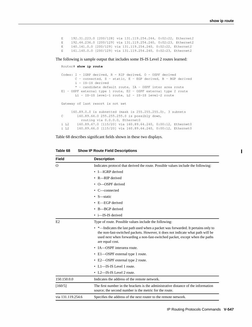
show ip route
IP Routing Protocols Commands V-547
E 192.31.223.0 [200/128] via 131.119.254.244, 0:02:22, Ethernet2E 192.44.236.0 [200/129] via 131.119.254.240, 0:02:23, Ethernet2E 140.141.0.0 [200/129] via 131.119.254.240, 0:02:22, Ethernet2E 141.140.0.0 [200/129] via 131.119.254.240, 0:02:23, Ethernet2
The following is sample output that includes some IS-IS Level 2 routes learned:
Router# show ip route
Codes: I - IGRP derived, R - RIP derived, O - OSPF derived C - connected, S - static, E - EGP derived, B - BGP derived i - IS-IS derived * - candidate default route, IA - OSPF inter area routeE1 - OSPF external type 1 route, E2 - OSPF external type 2 route L1 - IS-IS level-1 route, L2 - IS-IS level-2 route
Gateway of last resort is not set
160.89.0.0 is subnetted (mask is 255.255.255.0), 3 subnetsC 160.89.64.0 255.255.255.0 is possibly down, routing via 0.0.0.0, Ethernet0i L2 160.89.67.0 [115/20] via 160.89.64.240, 0:00:12, Ethernet0i L2 160.89.66.0 [115/20] via 160.89.64.240, 0:00:12, Ethernet0
Table 68 describes significant fields shown in these two displays.
Table 68 Show IP Route Field Descriptions
Field Description
O Indicates protocol that derived the route. Possible values include the following:
• I—IGRP derived
• R—RIP derived
• O—OSPF derived
• C—connected
• S—static
• E—EGP derived
• B—BGP derived
• i—IS-IS derived
E2 Type of route. Possible values include the following:
• *—Indicates the last path used when a packet was forwarded. It pertains only tothe non-fast-switched packets. However, it does not indicate what path will beused next when forwarding a non-fast-switched packet, except when the pathsare equal cost.
• IA—OSPF interarea route.
• E1—OSPF external type 1 route.
• E2—OSPF external type 2 route.
• L1—IS-IS Level 1 route.
• L2—IS-IS Level 2 route.
150.150.0.0 Indicates the address of the remote network.
[160/5] The first number in the brackets is the administrative distance of the informationsource; the second number is the metric for the route.
via 131.119.254.6 Specifies the address of the next router to the remote network.

V-548 Network Protocols Command Reference, Part 1
show ip route
When you specify that you want information about a specific network displayed, more detailedstatistics are shown. The following is sample output from theshow ip route command when enteredwith the address 131.119.0.0.
Router# show ip route 131.119.0.0
Routing entry for 131.119.0.0 (mask 255.255.0.0)Known via "igrp 109", distance 100, metric 10989Tag 0Redistributing via igrp 109Last update from 131.108.35.13 on TokenRing0, 0:00:58 agoRouting Descriptor Blocks:* 131.108.35.13, from 131.108.35.13, 0:00:58 ago, via TokenRing0
Route metric is 10989, traffic share count is 1Total delay is 45130 microseconds, minimum bandwidth is 1544 KbitReliability 255/255, minimum MTU 1500 bytesLoading 2/255, Hops 4
Table 69 describes significant fields shown in the display.
0:01:00 Specifies the last time the route was updated in hours:minutes:seconds.
Ethernet 2 Specifies the interface through which the specified network can be reached.
Table 69 Show IP Route with Address Field Descriptions
Field Description
Routing entry for 131.119.0.0 (mask255.255.0.0)
Network number and mask.
Known via “igrp 109” Indicates how the route was derived.
distance 100 Administrative distance of the information source.
Tag 0 Integer that is used to implement the route.
Redistributing via igrp 109 Indicates redistribution protocol.
Last update from 131.108.35.13 onTokenRing0
Indicates the IP address of a router that is the next hop to theremote network and the router interface on which the lastupdate arrived.
0:00:58 ago Specifies the last time the route was updated inhours:minutes:seconds.
131.108.35.13, from 131.108.35.13,0:00:58 ago
Indicates the next hop address, the address of the gateway thatsent the update, and the time that has elapsed since this updatewas received in hours:minutes:seconds.
via TokenRing0 Interface for this route.
Route metric is 10989 This value is the best metric for this routing descriptor block.
traffic share count is 1 Number of uses for this routing descriptor block.
Total delay is 45130 microseconds Total propagation delay in microseconds.
minimum bandwidth is 1544 Kbit Minimum bandwidth encountered when transmitting dataalong this route.
Reliability 255/255 Likelihood of successful packet transmission expressed as anumber between 0 and 255 (255 is 100 percent reliability).
Table 68 Show IP Route Field Descriptions (Continued)
Field Description

show ip route
IP Routing Protocols Commands V-549
The following is sample output using thelonger-prefixes keyword. When thelonger-prefixeskeyword is included, the address and mask pair becomes the prefix, and any address that matchesthat prefix is displayed. Therefore, multiple addresses are displayed.
In the following example, the logical AND operation is performed on the source address 128.0.0.0and the mask 128.0.0.0, resulting in 128.0.0.0. Each destination in the routing table is also logicallyANDed with the mask and compared to that result of 128.0.0.0. Any destinations that fall into thatrange are displayed in the output.
Router# show ip route 128.0.0.0 128.0.0.0 longer-prefixes
Codes: C - connected, S - static, I - IGRP, R - RIP, M - mobile, B - BGP D - EIGRP, EX - EIGRP external, O - OSPF, IA - OSPF inter area E1 - OSPF external type 1, E2 - OSPF external type 2, E - EGP i - IS-IS, L1 - IS-IS level-1, L2 - IS-IS level-2, * - candidate default
Gateway of last resort is not set
S 134.134.0.0 is directly connected, Ethernet0S 131.131.0.0 is directly connected, Ethernet0S 129.129.0.0 is directly connected, Ethernet0S 128.128.0.0 is directly connected, Ethernet0S 198.49.246.0 is directly connected, Ethernet0S 192.160.97.0 is directly connected, Ethernet0S 192.153.88.0 is directly connected, Ethernet0S 192.76.141.0 is directly connected, Ethernet0S 192.75.138.0 is directly connected, Ethernet0S 192.44.237.0 is directly connected, Ethernet0S 192.31.222.0 is directly connected, Ethernet0S 192.16.209.0 is directly connected, Ethernet0S 144.145.0.0 is directly connected, Ethernet0S 140.141.0.0 is directly connected, Ethernet0S 139.138.0.0 is directly connected, Ethernet0S 129.128.0.0 is directly connected, Ethernet0 172.19.0.0 255.255.255.0 is subnetted, 1 subnetsC 172.19.64.0 is directly connected, Ethernet0 171.69.0.0 is variably subnetted, 2 subnets, 2 masksC 171.69.232.32 255.255.255.240 is directly connected, Ethernet0S 171.69.0.0 255.255.0.0 is directly connected, Ethernet0Router#
Related CommandsA dagger (†) indicates that the command is documented outside this chapter.
show interfaces tunnel†
show ip route summary
minimum MTU 1500 bytes Smallest MTU along the path.
Loading 2/255 Effective bandwidth of the route in kilobits per second/255 issaturation.
Hops 4 Hops to the destination or to the router where the route firstenters IGRP.
Table 69 Show IP Route with Address Field Descriptions (Continued)
Field Description

V-550 Network Protocols Command Reference, Part 1
show ip route summary
show ip route summaryTo display the current state of the routing table, use theshow ip route summary EXEC command.
show ip route summary
Syntax DescriptionThis command has no arguments or keywords.
Command ModeEXEC
Usage Guidelines
This command first appeared in Cisco IOS Release 10.0.
Sample DisplayThe following is sample output from the show ip route summary command:
Router# show ip route summary
Route Source Networks Subnets Overhead Memory (bytes)connected 0 3 126 360static 1 2 126 360igrp 109 747 12 31878 91080internal 3 360Total 751 17 32130 92160Router#
Table 70 describes the fields shown in the display:
Related Commandshow ip route
Table 70 Show IP Route Summary Field Descriptions
Field Description
Route Source Routing protocol name, or the keywordconnected, static or internal .Internal indicates those routes that are in the routing table that are notowned by any routing protocol.
Networks Number of prefixes that are present in the routing table for each routesource.
Subnets Number of subnets that are present in the routing table for each routesource, including host routes.
Overhead Any additional memory involved in allocating the routes for theparticular route source other than the memory specified in theMemory field.
Memory Number of bytes allocated to maintain all the routes for the particularroute source.

show ip route supernets-only
IP Routing Protocols Commands V-551
show ip route supernets-onlyTo display information about supernets, use theshow ip route supernets-only privileged EXECcommand.
show ip route supernets-only
Syntax DescriptionThis command has no arguments or keywords.
Command ModePrivileged EXEC
Usage GuidelinesThis command first appeared in Cisco IOS Release 10.0.
Sample DisplayThe following is sample output from theshow ip route supernets-only command:
Router# show ip route supernets-only
Codes: I - IGRP derived, R - RIP derived, O - OSPF derived C - connected, S - static, E - EGP derived, B - BGP derived i - IS-IS derived, D - EIGRP derived * - candidate default route, IA - OSPF inter area route E1 - OSPF external type 1 route, E2 - OSPF external type 2 route L1 - IS-IS level-1 route, L2 - IS-IS level-2 route EX - EIGRP external route
Gateway of last resort is not set
B 198.92.0.0 (mask is 255.255.0.0) [20/0] via 198.92.72.30, 0:00:50B 192.0.0.0 (mask is 255.0.0.0) [20/0] via 198.92.72.24, 0:02:50Router#
This display shows supernets only; it does not show subnets.
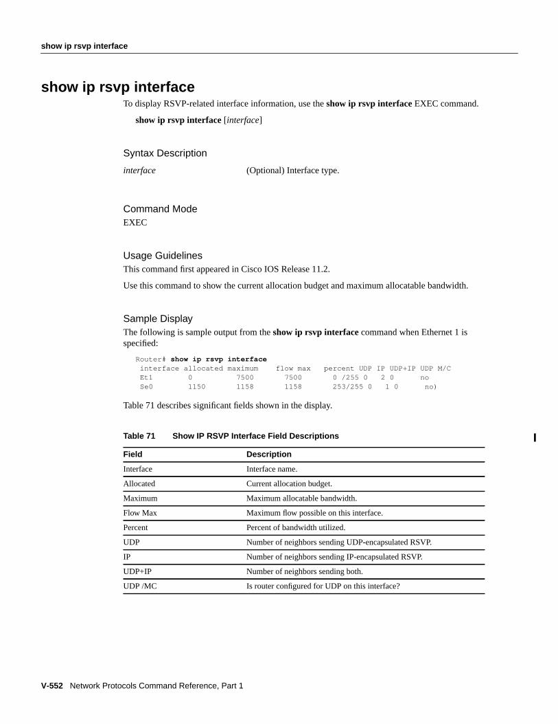
V-552 Network Protocols Command Reference, Part 1
show ip rsvp interface
show ip rsvp interfaceTo display RSVP-related interface information, use theshow ip rsvp interface EXEC command.
show ip rsvp interface[interface]
Syntax Description
Command ModeEXEC
Usage GuidelinesThis command first appeared in Cisco IOS Release 11.2.
Use this command to show the current allocation budget and maximum allocatable bandwidth.
Sample DisplayThe following is sample output from theshow ip rsvp interface command when Ethernet 1 isspecified:
Router# show ip rsvp interface interface allocated maximum flow max percent UDP IP UDP+IP UDP M/C Et1 0 7500 7500 0 /255 0 2 0 no Se0 1150 1158 1158 253/255 0 1 0 no)
Table 71 describes significant fields shown in the display.
interface (Optional) Interface type.
Table 71 Show IP RSVP Interface Field Descriptions
Field Description
Interface Interface name.
Allocated Current allocation budget.
Maximum Maximum allocatable bandwidth.
Flow Max Maximum flow possible on this interface.
Percent Percent of bandwidth utilized.
UDP Number of neighbors sending UDP-encapsulated RSVP.
IP Number of neighbors sending IP-encapsulated RSVP.
UDP+IP Number of neighbors sending both.
UDP /MC Is router configured for UDP on this interface?

show ip rsvp interface installed
IP Routing Protocols Commands V-553
show ip rsvp interface installedTo display RSVP-related installed filters and corresponding bandwidth information, use theshow iprsvp interface EXEC command.
show ip rsvp interface installed[interface]
Syntax Description
Command ModeEXEC
Usage GuidelinesThis command first appeared in Cisco IOS Release 11.2.
Use this command to show the current installed RSVP filters and the corresponding bandwidthinformation for a specified interface or all interfaces.
Sample DisplayThe following is sample output from theshow ip rsvp interface installedcommand:
Router# show ip rsvp interface installedRSVP:RSVP: Ethernet1: has no installed reservationsRSVP: Serial0: kbps To From Protocol DPort Sport Weight Conversation 0 224.250.250.1 132.240.2.28 UDP 20 30 128 270 150 224.250.250.1 132.240.2.1 UDP 20 30 128 268 100 224.250.250.1 132.240.1.1 UDP 20 30 128 267 200 224.250.250.1 132.240.1.25 UDP 20 30 256 265 200 224.250.250.2 132.240.1.25 UDP 20 30 128 271 0 224.250.250.2 132.240.2.28 UDP 20 30 128 269 150 224.250.250.2 132.240.2.1 UDP 20 30 128 266 350 224.250.250.3 0.0.0.0 UDP 20 0 128 26
interface (Optional) Interface type.

V-554 Network Protocols Command Reference, Part 1
show ip rsvp interface installed
Table 72 describes significant fields shown in the display.
Table 72 Show IP RSVP Interface Installed Field Descriptions
Field Description
kbps Interface name.
To IP address of source device.
From IP address of destination device.
Protocol DPort Protocol type of destination UDP/TCP port (not usually the protocolany more).
Sport Source UDP/TCP port.
Weight Weight used in Weighted Fair Queuing (WFQ).
Conversation WFQ conversation number. If the WFQ is not configured on theinterface, weight and conversation will be zero.

show ip rsvp neighbor
IP Routing Protocols Commands V-555
show ip rsvp neighborTo display current RSVP neighbors, use theshow ip rsvp neighborEXEC command.
show ip rsvp neighbor[interface]
Syntax Description
Command ModeEXEC
Usage GuidelinesThis command first appeared in Cisco IOS Release 11.2.
Use this command to show the current RSVP neighbors and identify if the neighbor is using IP orUDP encapsulation for a specified interface or all interfaces.
Sample DisplayThe following is sample output from theshow ip rsvp neighborcommand:
Router# show ip rsvp neighbor
RSVP: Et1 neighbors: IP 132.240.3.25 IP 132.240.3.28RSVP: Se0 neighbors: IP 132.240.4.30
interface (Optional) Interface type.

V-556 Network Protocols Command Reference, Part 1
show ip rsvp sender
show ip rsvp senderTo display RSVP-related sender information currently in the database, use theshow ip rsvp senderEXEC command.
show ip rsvp sender[interface]
Syntax Description
Command ModeEXEC
Usage GuidelinesThis command first appeared in Cisco IOS Release 11.2.
Use this command to show the current RSVP sender (PATH) information currently in the databasefor a specified interface or all interfaces.
Sample DisplayThe following is sample output from theshow ip rsvp sendercommand:
Router# show ip rsvp senderTo From Protocol DPort Sport Previous Hop If Kbps 224.250.250.1 132.240.1.1 UDP 20 30 132.240.3.25 Lo1 50 5 224.250.250.2 132.240.1.1 UDP 20 30 132.240.3.25 Lo1 50 5 224.250.250.2 132.240.1.25 UDP 20 30 132.240.3.25 Lo1 50 5 224.250.250.2 132.240.2.1 UDP 20 30 132.240.3.28 Lo1 50 5 224.250.250.2 132.240.2.28 UDP 20 30 132.240.3.28 Lo1 50 5 224.250.250.3 132.240.1.1 UDP 20 30 132.240.3.25 Lo1 50 5 224.250.250.3 132.240.1.25 UDP 20 30 132.240.3.25 Lo1 50 5 224.250.250.3 132.240.2.1 UDP 20 30 132.240.3.28 Lo1 50 5 224.250.250.3 132.240.2.28 UDP 20 30 132.240.3.28 Lo1 50 5
interface (Optional) Interface type.

show ip rsvp request
IP Routing Protocols Commands V-557
show ip rsvp requestTo display RSVP-related request information being requested upstream, use theshow ip rsvprequestEXEC command.
show ip rsvp request[interface]
Syntax Description
Command ModeEXEC
Usage GuidelinesThis command first appeared in Cisco IOS Release 11.2.
Use this command to show the RSVP reservations currently being requested upstream for a specifiedinterface or all interfaces. The received reservations may differ from requests because of aggregatedor refused reservations.
Sample DisplayThe following is sample output from theshow ip rsvp requestcommand:
Router# show ip rsvp requestTo From Protocol DPort Sport Next Hop If Filter Service B/W Burst224.250.250.1 132.240.1.1 UDP 20 30 132.240.3.25 Et1 FF DELY 1 100 60224.250.250.1 132.240.1.25 UDP 20 30 132.240.3.25 Et1 FF DELY 2 200 60224.250.250.1 132.240.2.1 UDP 20 30 132.240.3.28 Et1 FF DELY 1 150 65224.250.250.2 132.240.1.25 UDP 20 30 132.240.3.25 Et1 SE RATE 200 60224.250.250.2 132.240.2.1 UDP 20 30 132.240.3.28 Et1 SE LOAD 150 65224.250.250.3 0.0.0.0 UDP 20 0 132.240.3.25 Et1 WF LOAD 300 60
interface (Optional) Interface type.
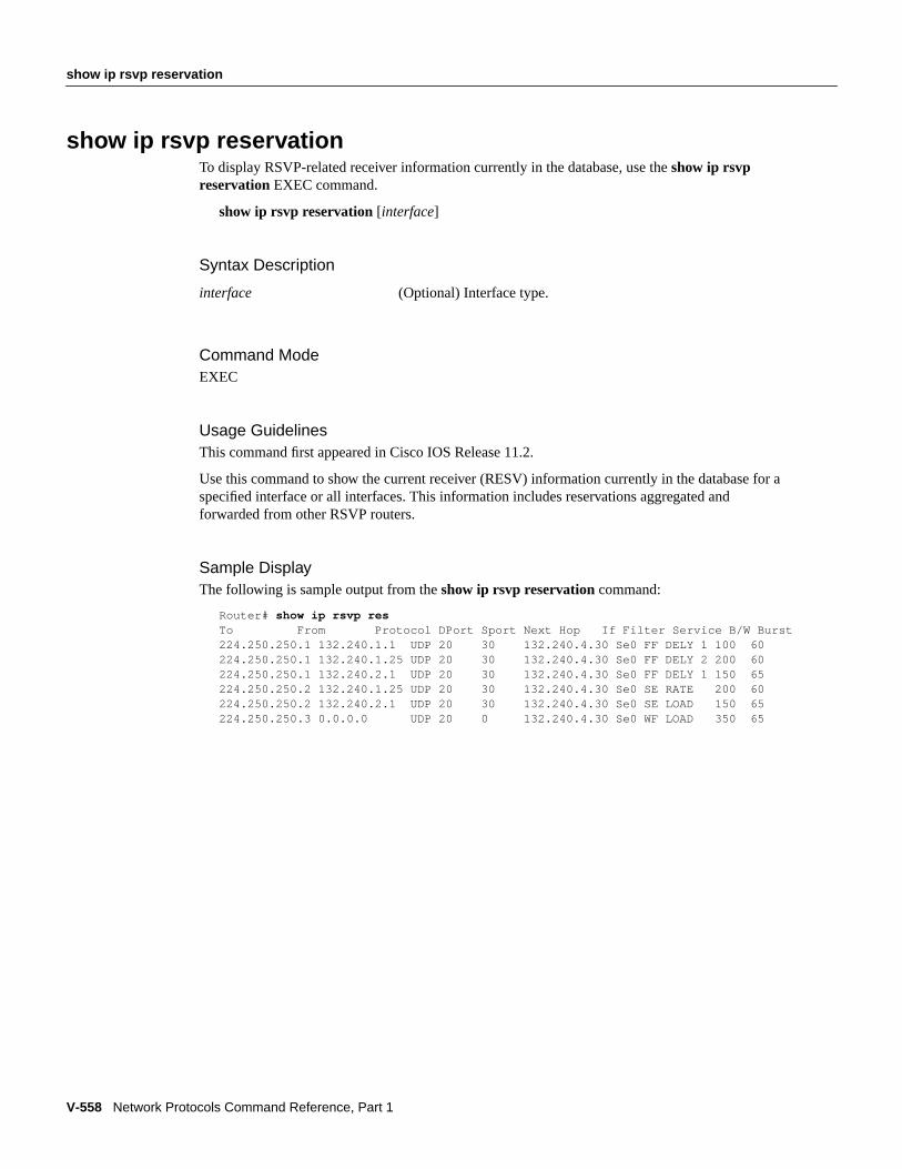
V-558 Network Protocols Command Reference, Part 1
show ip rsvp reservation
show ip rsvp reservationTo display RSVP-related receiver information currently in the database, use theshow ip rsvpreservationEXEC command.
show ip rsvp reservation[interface]
Syntax Description
Command ModeEXEC
Usage GuidelinesThis command first appeared in Cisco IOS Release 11.2.
Use this command to show the current receiver (RESV) information currently in the database for aspecified interface or all interfaces. This information includes reservations aggregated andforwarded from other RSVP routers.
Sample DisplayThe following is sample output from theshow ip rsvp reservationcommand:
Router# show ip rsvp resTo From Protocol DPort Sport Next Hop If Filter Service B/W Burst224.250.250.1 132.240.1.1 UDP 20 30 132.240.4.30 Se0 FF DELY 1 100 60224.250.250.1 132.240.1.25 UDP 20 30 132.240.4.30 Se0 FF DELY 2 200 60224.250.250.1 132.240.2.1 UDP 20 30 132.240.4.30 Se0 FF DELY 1 150 65224.250.250.2 132.240.1.25 UDP 20 30 132.240.4.30 Se0 SE RATE 200 60224.250.250.2 132.240.2.1 UDP 20 30 132.240.4.30 Se0 SE LOAD 150 65224.250.250.3 0.0.0.0 UDP 20 0 132.240.4.30 Se0 WF LOAD 350 65
interface (Optional) Interface type.

show ip sd
IP Routing Protocols Commands V-559
show ip sdTo display the contents of the session directory cache, use theshow ip sdEXEC command.
show ip sd[group |“session-name” | detail]
Syntax Description
Command ModeEXEC
Usage GuidelinesThis command first appeared in Cisco IOS Release 11.0.
If the Cisco IOS software is configured to be a member of 224.2.127.255 (the default sessiondirectory group), it will cache session directory announcements. If no arguments are used, a sortedlist of session names is displayed.
Sample DisplayThe following is sample output from theshow ip sdcommand, showing each session that thesoftware has learned:
Router> show ip sd
SD Cache - 22 entries *cisco: CABONE Audio *cisco: CABONE Video *cisco: CABONE Whiteboard *cisco: CBONE audio *cisco: CBONE video *cisco: CBONE Whiteboard *cisco: CCIE Audio *cisco:Eng Services Ops Review *cisco:Scamp's Managers Meeting A3TEST aki APLtest arch-nus Bharat Dave-ETH cbone CERN - LHCC
group (Optional) Displays the sessions defining the multicast group indetail format.
“session-name” (Optional) Displays the single session in detail format. Can bein uppercase or lowercase and still match. The session name isenclosed in quotation marks.
detail (Optional) Displays all sessions in detail format.

V-560 Network Protocols Command Reference, Part 1
show ip sd
cisco: Beta Folks DB DECUS '95: Marc Andreessen (audio) DECUS '95: Marc Andreessen (vic/h261) Digital Unix Multicast DSTC Fun with whiteboard
The following is sample output from theshow ip sd detailcommand:
Router# show ip sd detail
SD Cache - 3 entriesSession Name: *cisco: CABONE Audio Description: cisco Customer Advocacy Audio Channel Group: 224.0.255.128, ttl: 16 Lifetime: from 00:00:24 PDT May 9 1995 until 00:00:24 PDT May 23 1995 Created by: [email protected] (171.68.225.179) Media: audio 55557 2688 --More--Session Name: *cisco: CABONE Video Description: cisco Customer Advocacy Video Channel Group: 224.0.255.130, ttl: 16 Lifetime: from 00:00:56 PDT May 9 1995 until 00:00:56 PDT May 23 1995 Created by: [email protected] (171.68.225.179) Media: video 62676 63933 --More--Session Name: *cisco: CABONE Whiteboard Description: cisco Customer Advocacy Whiteboard Group: 224.0.255.129, ttl: 16 Lifetime: from 00:00:30 PDT May 9 1995 until 00:00:30 PDT May 23 1995 Created by: [email protected] (171.68.225.179) Media: whiteboard 43411 14736
Table 73 describes the significant fields in the display.
Table 73 Show IP SD Field Descriptions
Field Description
Session Name Name of the session.
Description Description of the session.
Group Group address.
ttl Time-to-live for the session.
Lifetime Lifetime of the session advertisement.
Created by Creator of the session.
Media Type of media, port number and conference ID.

show isis database
IP Routing Protocols Commands V-561
show isis databaseTo display the IS-IS link state database, use theshow isis database EXEC command.
show isis database[level-1] [ level-2] [ l1] [ l2] [detail] [ lspid]
Syntax Description
Command ModeEXEC
Usage GuidelinesThis command first appeared in Cisco IOS Release 10.0.
Each of the options shown in brackets for this command can be entered in an arbitrary string withinthe same command entry. For example, the following are both valid command specifications andprovide the same output:show isis database detail l2 andshow isis database l2 detail.
Sample DisplayThe following is sample output from theshow isis database command when it is specified with nooptions or asshow isis database l1 l2:
Router# show isis database
IS-IS Level-1 Link State DatabaseLSPID LSP Seq Num LSP Checksum LSP Holdtime ATT/P/OL0000.0C00.0C35.00-00 0x0000000C 0x5696 792 0/0/00000.0C00.40AF.00-00* 0x00000009 0x8452 1077 1/0/00000.0C00.62E6.00-00 0x0000000A 0x38E7 383 0/0/00000.0C00.62E6.03-00 0x00000006 0x82BC 384 0/0/00800.2B16.24EA.00-00 0x00001D9F 0x8864 1188 1/0/00800.2B16.24EA.01-00 0x00001E36 0x0935 1198 1/0/0
IS-IS Level-2 Link State DatabaseLSPID LSP Seq Num LSP Checksum LSP Holdtime ATT/P/OL0000.0C00.0C35.03-00 0x00000005 0x04C8 792 0/0/00000.0C00.3E51.00-00 0x00000007 0xAF96 758 0/0/00000.0C00.40AF.00-00* 0x0000000A 0x3AA9 1077 0/0/0
Table 74 describes significant fields shown in the display.
level-1 (Optional) Displays the IS-IS link state database for Level 1.
level-2 (Optional) Displays the IS-IS link state database for Level 2.
l1 (Optional) Abbreviation for the optionlevel-1.
l2 (Optional) Abbreviation for the optionlevel-2.
detail (Optional) When specified, the contents of each LSP isdisplayed. Otherwise, a summary display is provided.
lspid (Optional) Link-state protocol ID. When specified, the contentsof a single LSP is displayed by its ID number.

V-562 Network Protocols Command Reference, Part 1
show isis database
Sample Display Using Show IS-IS Database DetailThe following is sample output from theshow isis database detail command.
Router# show isis database detail
IS-IS Level-1 Link State DatabaseLSPID LSP Seq Num LSP Checksum LSP Holdtime ATT/P/OL0000.0C00.0C35.00-00 0x0000000C 0x5696 325 0/0/0
Area Address: 47.0004.004D.0001Area Address: 39.0001Metric: 10 IS 0000.0C00.62E6.03Metric: 0 ES 0000.0C00.0C35
--More--0000.0C00.40AF.00-00* 0x00000009 0x8452 608 1/0/0
Area Address: 47.0004.004D.0001Metric: 10 IS 0800.2B16.24EA.01Metric: 10 IS 0000.0C00.62E6.03Metric: 0 ES 0000.0C00.40AF
IS-IS Level-2 Link State DatabaseLSPID LSP Seq Num LSP Checksum LSP Holdtime ATT/P/OL0000.0C00.0C35.03-00 0x00000005 0x04C8 317 0/0/0 Metric: 0 IS 0000.0C00.0C35.00 --More--0000.0C00.3E51.00-00 0x00000009 0xAB98 1182 0/0/0
Area Address: 39.0004Metric: 10 IS 0000.0C00.40AF.00Metric: 10 IS 0000.0C00.3E51.05
As the output shows, in addition to the information displayed withshow isis database, theshow isisdatabase detail command displays the contents of each LSP.
Table 75 describes the fields shown in the display.
Table 74 Show IS-IS Database Field Descriptions
Field Description
LSPID The link state PDU ID. The first six octets form the System ID. Thenext octet is the pseudo ID. When this value is zero, the LSP describeslinks from the system. When it is nonzero, the LSP is a pseudonodeLSP. The designated router for an interface is the only system thatoriginates pseudonode LSPs. The last octet is the LSP number. If thereis more data than can fit in a single LSP, additional LSPs are sent withincreasing LSP numbers. An asterisk (*) indicates that the LSP wasoriginated by the local system.
LSP Seq Num Sequence number for the LSP that allows other systems to determineif they have received the latest information from the source.
LSP Checksum Checksum of the entire LSP packet.
LSP Holdtime Amount of time the LSP remains valid, in seconds.
ATT The Attach bit. This indicates that the router is also a Level 2 router,and it can reach other areas.
P The P bit. Detects if the IS is area partition repair capable.
OL The Overload bit. Determines if the IS is congested.

show isis database
IP Routing Protocols Commands V-563
Sample Display Using Show IS-IS Database Detail Displaying IP AddressesThe following is additional sample output from theshow isis database detail command.This is aLevel 2 LSP. The area address 39.0001 is the address of the area in which the router resides.
Router# show isis database detail l2
IS-IS Level-2 Link State DatabaseLSPID LSP Seq Num LSP Checksum LSP Holdtime ATT/P/OL0000.0C00.1111.00-00* 0x00000006 0x4DB3 1194 0/0/0 Area Address: 39.0001 NLPID: 0x81 0xCC IP Address: 160.89.64.17 Metric: 10 IS 0000.0C00.1111.09 Metric: 10 IS 0000.0C00.1111.08 Metric: 10 IP 160.89.65.0 255.255.255.0 Metric: 10 IP 160.89.64.0 255.255.255.0 Metric: 0 IP-External 10.0.0.0 255.0.0.0
Table 76 describes the fields shown in the display.
Table 75 Show IS-IS Database Detail Field Descriptions
Field Description
LSPID The link state PDU ID. The first six octets form the System ID. The next octet isthe pseudo ID. When this value is zero, the LSP describes links from the system.When it is nonzero, the LSP is a pseudonode LSP. The designated router for aninterface is the only system that originates pseudonode LSPs. The last octet is theLSP number. If there is more data than can fit in a single LSP, additional LSPs aresent with increasing LSP numbers. An asterisk (*) indicates that the LSP wasoriginated by the local system.
LSP Seq Num Sequence number for the LSP that allows other systems to determine if they havereceived the latest information from the source.
LSP Checksum Checksum of the entire LSP packet.
LSP Holdtime Amount of time the LSP remains valid, in seconds.
ATT The attach bit. This indicates that the router is also a Level 2 router, and it canreach other areas.
P The P bit. Detects if the IS is area partition-repair-capable.
OL The Overload bit. Determines if the IS is congested.
Area Address: Reachable area addresses from the router.
Metric: IS-IS metric for the route.
Table 76 Show IS-IS Database Detail Field Descriptions Displaying IP Addresses
Field Description
LSPID The link state PDU ID. The first six octets form the System ID. The next octet isthe pseudo ID. When this value is zero, the LSP describes links from the system.When it is nonzero, the LSP is a pseudonode LSP. The designated router for aninterface is the only system that originates pseudonode LSPs. The last octet isthe LSP number. If there is more data than can fit in a single LSP, additionalLSPs are sent with increasing LSP numbers. An asterisk (*) indicates that theLSP was originated by the local system.
LSP Seq Num Sequence number for the LSP that allows other systems to determine if theyhave received the latest information from the source.

V-564 Network Protocols Command Reference, Part 1
show isis database
LSP Checksum Checksum of the entire LSP packet.
LSP Holdtime Amount of time the LSP remains valid, in seconds.
ATT The attach bit. This indicates that the router is also a Level 2 router, and it canreach other areas.
P The P bit. Detects if the IS is area partition repair capable.
OL The Overload bit. Determines if the IS is congested.
Area Address: Reachable area addresses from the router.
NLPID Indicates that both IP and OSI (0x0cc and 0x081 respectively) are supported inIS-IS for this router.
IP Address: The IP address for the router is advertised in the LSP.
Metric: IS-IS metric for the route.
Various addresses The “IP” entries are the directly connected IP subnets the router is advertising(with associated metrics). The “IP-External” is a redistribute route.
Table 76 Show IS-IS Database Detail Field Descriptions Displaying IP Addresses (Continued)
Field Description

show key chain
IP Routing Protocols Commands V-565
show key chainTo display authentication key information, use the show key chainEXEC command.
show key chain [name-of-chain]
Syntax Description
DefaultInformation about all key chains is displayed.
Command ModeEXEC
Usage GuidelinesThis command first appeared in Cisco IOS Release 11.1.
Sample DisplayThe following is sample output from theshow key chain command:
Router# show key chainKey-chain flintstone: key 1 -- text "fred" accept lifetime (always valid) - (always valid) [valid now] send lifetime (always valid) - (always valid) [valid now] key 2 -- text "barney" accept lifetime (00:00:00 Dec 5 1995) - (23:59:59 Dec 5 1995) send lifetime (06:00:00 Dec 5 1995) - (18:00:00 Dec 5 1995)
Related Commandsaccept-lifetimekeykey chainkey-stringsend-lifetime
name-of-chain (Optional) Name of the key chain to display, as named in thekey chaincommand.

V-566 Network Protocols Command Reference, Part 1
show route-map
show route-mapTo display configured route-maps, use theshow route-map EXEC command.
show route-map[map-name]
Syntax Description
Command ModeEXEC
Usage Guidelines
This command first appeared in Cisco IOS Release 10.0.
Sample DisplayThe following is sample output from the show route-map command:
Router# show route-map
route-map foo, permit, sequence 10 Match clauses: tag 1 2 Set clauses: metric 5route-map foo, permit, sequence 20 Match clauses: tag 3 4 Set clauses: metric 6
Table 77 describes the fields shown in the display:
Related Commandsredistributeroute-map
map-name (Optional) Name of a specific route-map.
Table 77 Show Route-Map Field Descriptions
Field Description
route-map Name of the route map.
permit Indicates that the route is redistributed as controlled by the set actions.
sequence Number that indicates the position a new route map is to have in thelist of route maps already configured with the same name.
Match clausestag
Match criteria—conditions under which redistribution is allowed forthe current route map.
Set clausesmetric
Set actions—the particular redistribution actions to perform if thecriteria enforced by thematch commands are met.

summary-address
IP Routing Protocols Commands V-567
summary-addressUse thesummary-address router configuration command to create aggregate addresses for IS-IS orOSPF. Theno summary-addresscommand restores the default.
summary-address address mask{ level-1 | level-1-2 | level-2} prefix mask[not-advertise][tag tag]
no summary-address address mask{ level-1 | level-1-2 | level-2}
Syntax Description
DefaultDisabled
Command ModeRouter configuration
Usage GuidelinesThis command first appeared in Cisco IOS Release 10.0.
Multiple groups of addresses can be summarized for a given level. Routes learned from other routingprotocols can also be summarized. The metric used to advertise the summary is the smallest metricof all the more specific routes. This command helps reduce the size of the routing table.
address Summary address designated for a range of addresses.
mask IP subnet mask used for the summary route.
level-1 Only routes redistributed into Level 1 are summarized withthe configured address/mask value. This keyword does notapply to OSPF.
level-1-2 The summary router is injected into both a Level 1 area anda Level 2 subdomain. This keyword does not apply toOSPF.
level-2 Routes learned by Level 1 routing will be summarized intothe Level 2 backbone with the configured address/maskvalue. This keyword does not apply to OSPF.
prefix IP route prefix for the destination.
mask IP subnet mask used for the summary route.
not-advertise Used to suppress routes that match the prefix/mask pair.
tag tag (Optional) Tag value that can be used as a “match” valuefor controlling redistribution via route maps.

V-568 Network Protocols Command Reference, Part 1
summary-address
Using this command for OSPF causes an OSPF autonomous system boundary router (ASBR) toadvertise one external route as an aggregate for all redistributed routes that are covered by theaddress. For OSPF, this command summarizes only routes from other routing protocols that arebeing redistributed into OSPF. Use thearea range command for route summarization betweenOSPF areas.
Example for IS-ISIn the following example, summary address 10.1.0.0 includes address 10.1.1, 10.1.2, 10.1.3, 10.1.4,and so forth. Only the address 10.1.0.0 is advertised in an IS-IS Level 1 Link State PDU.
summary-address 10.1.0.0 255.255.0.0 level-1
Example for OSPFIn the following example, summary address 10.1.0.0 includes address 10.1.1.0, 10.1.2.0, 10.1.3.0,and so forth. Only the address 10.1.0.0 is advertised in an external link state advertisement.
summary-address 10.1.0.0 255.255.0.0
Related Commandsarea rangeip ospf authentication-keyip ospf message-digest-key

synchronization
IP Routing Protocols Commands V-569
synchronizationTo enable the synchronization between BGP and your IGP, use the synchronization routerconfiguration command. To enable the Cisco IOS software to advertise a network route withoutwaiting for the IGP, use theno form of this command.
synchronizationno synchronization
Syntax DescriptionThis command has no arguments or keywords.
DefaultEnabled
Command ModeRouter configuration
Usage GuidelinesThis command first appeared in Cisco IOS Release 10.0.
Usually, a BGP speaker does not advertise a route to an external neighbor unless that route is localor exists in the IGP. The no synchronization command allows the Cisco IOS software to advertisea network route without waiting for the IGP. This feature allows routers and access servers within anautonomous system to have the route before BGP makes it available to other autonomous systems.
Usesynchronization if there are routers in the autonomous system that do not speak BGP.
ExampleThe following example enables a router to advertise a network route without waiting for the IGP:
router bgp 120no synchronization

V-570 Network Protocols Command Reference, Part 1
table-map
table-mapTo modify metric and tag values when the IP routing table is updated with BGP learned routes, usethe table-map router configuration command. To disable this function, use theno form of thecommand.
table-map route-map-nameno table-maproute-map-name
Syntax Description
DefaultDisabled
Command ModeRouter configuration
Usage GuidelinesThis command first appeared in Cisco IOS Release 10.0.
This command adds the route-map name defined by theroute-map command to the IP routing table.This command is used to set the tag name and the route metric to implement redistribution.
You can usematch clauses of route maps in thetable-map command. IP access list, autonomoussystem paths, and next-hop match clauses are supported.
ExampleIn the following example, the Cisco IOS software is configured to automatically compute the tagvalue for the BGP learned routes and to update the IP routing table.
route-map tagmatch as path 10set automatic-tag!router bgp 100table-map tag
Related Commandsmatch as-pathmatch ip addressmatch ip next-hoproute-map
route-map-name Route-map name, from the route-map command.
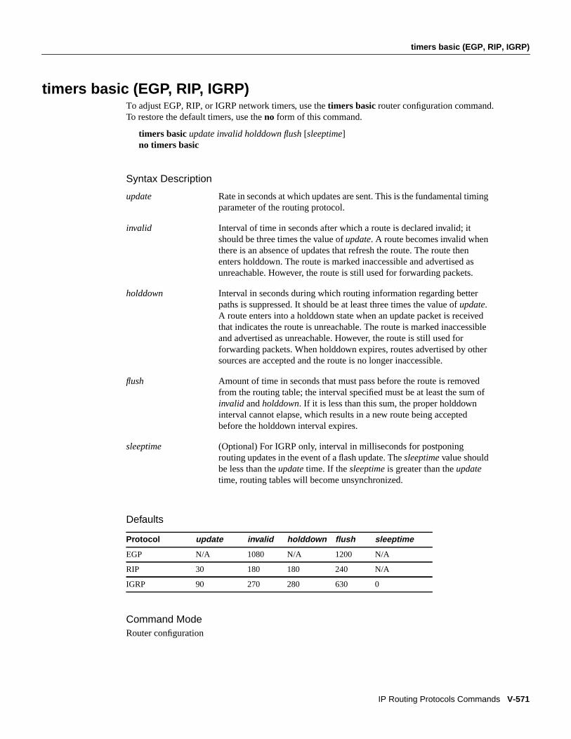
timers basic (EGP, RIP, IGRP)
IP Routing Protocols Commands V-571
timers basic (EGP, RIP, IGRP)To adjust EGP, RIP, or IGRP network timers, use the timers basic router configuration command.To restore the default timers, use theno form of this command.
timers basic update invalid holddown flush[sleeptime]no timers basic
Syntax Description
Defaults
Command ModeRouter configuration
update Rate in seconds at which updates are sent. This is the fundamental timingparameter of the routing protocol.
invalid Interval of time in seconds after which a route is declared invalid; itshould be three times the value ofupdate. A route becomes invalid whenthere is an absence of updates that refresh the route. The route thenenters holddown. The route is marked inaccessible and advertised asunreachable. However, the route is still used for forwarding packets.
holddown Interval in seconds during which routing information regarding betterpaths is suppressed. It should be at least three times the value ofupdate.A route enters into a holddown state when an update packet is receivedthat indicates the route is unreachable. The route is marked inaccessibleand advertised as unreachable. However, the route is still used forforwarding packets. When holddown expires, routes advertised by othersources are accepted and the route is no longer inaccessible.
flush Amount of time in seconds that must pass before the route is removedfrom the routing table; the interval specified must be at least the sum ofinvalid andholddown. If it is less than this sum, the proper holddowninterval cannot elapse, which results in a new route being acceptedbefore the holddown interval expires.
sleeptime (Optional) For IGRP only, interval in milliseconds for postponingrouting updates in the event of a flash update. Thesleeptime value shouldbe less than theupdate time. If thesleeptime is greater than theupdatetime, routing tables will become unsynchronized.
Protocol update invalid holddown flush sleeptime
EGP N/A 1080 N/A 1200 N/A
RIP 30 180 180 240 N/A
IGRP 90 270 280 630 0

V-572 Network Protocols Command Reference, Part 1
timers basic (EGP, RIP, IGRP)
Usage GuidelinesThis command first appeared in Cisco IOS Release 10.0.
The basic timing parameters for IGRP, EGP, and RIP are adjustable. Since these routing protocolsare executing a distributed, asynchronous routing algorithm, it is important that these timers be thesame for all routers and access servers in the network.
Note The current and default timer values can be seen by inspecting the output of theshow ipprotocols EXEC command. The relationships of the various timers should be preserved as describedpreviously.
ExamplesIn the following example, updates are broadcast every 5 seconds. If a router is not heard from in15 seconds, the route is declared unusable. Further information is suppressed for an additional15 seconds. At the end of the suppression period, the route is flushed from the routing table.
router igrp 109timers basic 5 15 15 30
Note that by setting a short update period, you run the risk of congesting slow-speed serial lines;however, this is not a big concern on faster-speed Ethernets and T1-rate serial lines. Also, if you havemany routes in your updates, you can cause the routers to spend an excessive amount of timeprocessing updates.
When the timers basic command is used with EGP, the update time and holddown time are ignored.For example, the commands that follow will set the invalid time for EGP to 100 seconds and the flushtime to 200 seconds.
router egp 47timers basic 0 100 0 200

timers bgp
IP Routing Protocols Commands V-573
timers bgpTo adjust BGP networktimers, use the timers bgprouter configuration command. To reset the BGPtiming defaults, use theno form of this command.
timers bgp keepalive holdtimeno timers bgp
Syntax Description
Defaultskeepalive: 60 secondsholdtime: 180 seconds
Command ModeRouter configuration
Usage Guidelines
This command first appeared in Cisco IOS Release 10.0.
ExampleThe following example changes the keepalive timer to 70 seconds and the holdtime timer to210 seconds:
timers bgp 70 210
Related Commandsclear ip bgp peer-grouprouter bgpshow ip bgp
keepalive Frequency, in seconds, with which the Cisco IOS softwaresendskeepalive messages to its peer. The default is 60 seconds.
holdtime Interval, in seconds, after not receiving akeepalive message thatthe software declares a peer dead. The default is 180 seconds.

V-574 Network Protocols Command Reference, Part 1
timers egp
timers egpTo adjust EGP hello and polltime networktimers, use the timers egprouter configuration command.The no form of this command resets the EGP timing defaults.
timers egp hello polltimeno timers egp
Syntax Description
Defaultshello: 60 secondspolltime: 180 seconds
Command ModeRouter configuration
Usage GuidelinesThis command first appeared in Cisco IOS Release 10.0.
To change the invalid time or flush time for EGP routes, use thetimers basic router configurationcommand.
ExampleThe following example changes the EGP timers to 2 minutes and 5 minutes, respectively:
timers egp 120 300
Related Commandsrouter egpshow ip egptimers basic (EGP, RIP, IGRP)
hello Frequency, in seconds, with which the software sends Hellomessages to its peer. The default is 60 seconds.
polltime Interval, in seconds, for how frequently to exchange updates.The default is 180 seconds.

timers spf
IP Routing Protocols Commands V-575
timers spfTo configure the delay time between when OSPF receives a topology change and when it starts ashortest path first (SPF) calculation, and the hold time between two consecutive SPF calculations,use thetimers spf router configuration command. To return to the default timer values, use thenoform of this command.
timers spf spf-delay spf-holdtimeno timers spfspf-delay spf-holdtime
Syntax Description
Defaultsspf-delay: 5 secondsspf-holdtime: 10 seconds
Command ModeRouter configuration
Usage GuidelinesThis command first appeared in Cisco IOS Release 10.3.
Setting the delay and hold time low causes routing to switch to the alternate path more quickly in theevent of a failure. However, it consumes more CPU processing time.
ExampleThe following example changes the delay to 10 seconds and the hold time to 20 seconds:
timers spf 10 20
spf-delay Delay time, in seconds, between when OSPF receives atopology change and when it starts a SPF. calculation. It can bean integer from 0 to 65535. The default time is 5 seconds. Avalue of 0 means that there is no delay; that is, the SPFcalculation is started immediately.
spf-holdtime Minimum time, in seconds, between two consecutive SPFcalculations. It can be an integer from 0 to 65535. The defaulttime is 10 seconds. A value of 0 means that there is no delay;that is, two consecutive SPF calculations can be done oneimmediately after the other.

V-576 Network Protocols Command Reference, Part 1
traffic-share
traffic-shareTo control how traffic is distributed among routes when there are multiple routes for the samedestination network that have different costs, use the traffic-share router configuration command.To disable this function, use theno form of the command.
traffic-share { balanced | min}[no] traffic share { balanced | min}
Syntax Description
DefaultTraffic is distributed proportionately to the ratios of the metrics.
Command ModeRouter configuration
Usage GuidelinesThis command first appeared in Cisco IOS Release 10.0.
This command applies to IGRP and Enhanced IGRP routing protocols only. With the default setting,routes that have higher metrics represent less-preferable routes and get less traffic. Configuringtraffic-share min causes the Cisco IOS software to only divide traffic among the routes with the bestmetric. Other routes will remain in the routing table, but will receive no traffic.
ExampleIn the following example, only routes of minimum cost will be used:
router igrp 5traffic-share min
balanced Distributes traffic proportionately to the ratios of the metrics.
min Uses routes that have minimum costs.

validate-update-source
IP Routing Protocols Commands V-577
validate-update-sourceTo have the Cisco IOS software validate the source IP address of incoming routing updates for RIPand IGRP routing protocols, use the validate-update-sourcerouter configuration command. Todisable this function, use theno form of this command.
validate-update-sourceno validate-update-source
Syntax DescriptionThis command has no arguments or keywords.
DefaultEnabled
Command ModeRouter configuration
Usage GuidelinesThis command first appeared in Cisco IOS Release 10.0.
This command is only applicable to RIP and IGRP. The software ensures that the source IP addressof incoming routing updates is on the same IP network as one of the addresses defined for thereceiving interface.
Disabling split horizon on the incoming interface will also cause the system to perform thisvalidation check.
For unnumbered IP interfaces (interfaces configured asip unnumbered), no checking is performed.
ExampleIn the following example, a router is configured to not perform validation checks on the source IPaddress of incoming RIP updates:
router ripnetwork 128.105.0.0no validate-update-source

V-578 Network Protocols Command Reference, Part 1
variance
varianceTo control load balancing in an Enhanced IGRP-based internetwork, use the variance routerconfiguration command. To reset the variance to the default value, use the no form of this command.
variancemultiplierno variance
Syntax Description
Default1 (equal-cost load balancing)
Command ModeRouter configuration
Usage GuidelinesThis command first appeared in Cisco IOS Release 10.0.
Setting a variance value lets the Cisco IOS software determine the feasibility of a potential route. Aroute is feasible if the next router in the path is closer to the destination than the current router andif the metric for the entire path is within the variance. Only paths that are feasible can be used forload balancing and included in the routing table.
If the following two conditions are met, the route is deemed feasible and can be added to the routingtable:
1 The local best metric must be greater than the metric learned from the next router.
2 The multiplier times the local best metric for the destination must be greater than or equal to themetric through the next router.
ExampleThe following example sets a variance value of 4:
router igrp 109variance 4
multiplier Metric value used for load balancing. It can be a value from 1 to128. The default is 1, which means equal-cost load balancing.

version
IP Routing Protocols Commands V-579
versionTo specify a RIP version used globally by the router, use the version router configuration command.Use theno form of this command to restore the default value.
version { 1 | 2}no version
Syntax Description
DefaultThe software receives RIP Version 1 and Version 2 packets, but sends only Version 1 packets.
Command ModeRouter configuration
Usage GuidelinesThis command first appeared in Cisco IOS Release 11.1.
To specify RIP versions used on an interface basis, use theip rip receive version andip rip sendversion commands.
ExampleThe following example enables the software to send and receive RIP Version 2 packets:
version 2
Related Commandsip rip receive versionip rip send versionshow ip protocols
1 Specifies RIP Version 1.
2 Specifies RIP Version 2.

V-580 Network Protocols Command Reference, Part 1
version