ip-in-ip tunneling to enable the simultaneous use of ...phatak/publications/nstripe-comnet.pdf ·...
TRANSCRIPT

IP-in-IP Tunneling to Enable the Simultaneous Use of MultipleIP Interfaces for Network Level Connection Striping
Dhananjay S. Phatak Tom Goff Jim Plusquellic
Department of Computer Science and Electrical EngineeringUniversity of Maryland Baltimore County (UMBC)
1000 Hilltop CircleBaltimore, MD 21250
Email: {phatak,tgoff1,plusquel}@umbc.edu
March 14, 2003
Abstract
With ubiquitous computing and network access now a reality, multiple network conduits are becomewidely available to mobile as well as static hosts: for instance wired connections, 802.11 style LANs,Bluetooth, and cellular phone modems. Selection of the preferred mode of data transfer is a dynamic op-timization problem which depends on the type of application, its bandwidth/latency/jitter requirements,current network conditions (such as congestion or traffic patterns), cost, power consumption, batterylife, and so on. Furthermore, since wireless bandwidth is likely to remain a scarce resource, we foreseescenarios wherein mobile hosts will require simultaneous data transfer across multiple IP interfaces toobtain higher overall bandwidth.
We present a brief overview of existing work which enables the simultaneous use of multiple networkinterfaces and identify the applicability as well as strengths and weaknesses of these related approaches.We then propose a new mechanism to aggregate the bandwidth of multiple IP paths by splitting a dataflow across multiple network interfaces at the IP level. We have analyzed the performance characteristicsof our aggregation scheme and demonstrate significant gains when the network paths being aggregatedhave similar bandwidth and latency characteristics. In addition, our method is transparent to transport(TCP/UDP) and higher layers, and allows the use of multiple network interfaces to enhance reliability.Our analysis identifies the conditions under which the proposed scheme, or any other scheme that stripesa single TCP connection across multiple IP paths, can be used to increase throughput.
1 Introduction
As wireless networks, services, and computing continue their explosive growth it is clear that multi-ple network transport mechanisms will become available to hosts. For instance, a mobile host might have
This work was supported in part by Aether Systems Inc. and NSF grants ECS-9875705 and ECS-0196362.Portions of this work appeared in: D. S. Phatak and T. Goff, “A Novel Mechanism for Data Streaming Across Multiple IP
Links for Improving Throughput and Reliability in Mobile Environments,” in IEEE INFOCOM, pp. 773–781, June 2002.
1

access to the Internet via multiple networking technologies such as Bluetooth, wireless LANs (802.11, Air-port LANs, Ricochet, etc.), and cellular phone modem where each technology has a corresponding serviceprovider. Selecting which service to use for data transfer is a dynamic optimization problem which shouldtrack time varying attributes which might include bandwidth/throughput, latency, jitter, quality of service(QoS) requirements, cost, power consumption, residual battery life, interference, and traffic patterns. Also,wireless bandwidth is a scarce resource which is unlikely to improve at the same pace as the rapid growthin bandwidth available via wired networks. Hence it is probable that mobile users will want to simultane-ously stream data across multiple network interfaces in order to best make use of all available bandwidth.Therefore, this paper investigates the simultaneous use of multiple network interfaces to enhance the overallbandwidth available to a wireless node. An immediate secondary advantage is increased reliability, for ex-ample if one network interface goes down or one network path becomes severely congested the end-to-endconnection is not interrupted.
In some cases, such as military applications, multiple identical or very similar network access mecha-nisms are provided for the sake of reliability in hostile environments. Although though the primary motiva-tion for providing redundant network access is reliability, it would be desirable to stream distinct data packetsacross all interfaces simultaneously whenever possible. This would be a “performance enhancement” mode.When reliability becomes an issue, the data transfer could switch to a “reliability first” mode, where twoor more identical copies of the data stream might be sent across multiple access points in the hope that atleast one reaches its destination. Ideally there would be no hard cutoff between the performance enhance-ment and reliability first modes. In general a mixture could exist, for example only duplicate lost packetsfor transfer across multiple interfaces. Furthermore, the transition between performance-enhancement andreliability first modes should happen dynamically in reaction to the environment.
1.1 Problem Definition
Figure 1 illustrates the case when hosts A and B want to communicate via the Internet and both havemultiple transport conduits. For instance, host A might be a laptop at an airport with access to the Internetvia an 802.11 LAN (say interface A1), a Bluetooth scatternet (A2), and a cellular phone modem (A3). Ingeneral, the IP addresses assigned to interfaces A1, A2, and A3 will be controlled by separate Internet ServiceProviders (ISPs) who might in turn implement firewalling to various degrees.
HostB
HostA Internet
A3
ISPB1
ISPA1
ISPA2
ISPA3
ISPB2
B1
B2
A1
A2
Figure 1: Communicating Hosts With Multiple Network Connections (Multi-Homed)
Suppose A wants to stream data to B across multiple interfaces to enhance the overall bandwidth. Sev-eral questions arise when considering the possible ways to achieve this effect. Should the data stream besplit into multiple streams at the application level? In this case the application would open multiple con-nections across different network interfaces and be responsible for splitting the data stream at the server and
2

merging it properly at the client. This approach might be too cumbersome and restrictive since the numberof connections might have to be decided in advance in order to figure out how many flows to split the trafficinto. Alternatively, should the splitting be done at transport layer or at the network layer? In essence weare considering this general question of striping a connection across multiple IP interfaces for bandwidthaggregation.
1.2 Related Work
Bandwidth aggregation across multiple channels has been considered in the literature in varying contextsand for different applications and scenarios, distinct from those considered in this paper. For instance, multi-link PPP [1, 2, 3] is designed to aggregate multiple logical data channels into one. Since PPP was intendedto operate at the data link layer, below the IP level [4, 5, 6], the multi-link PPP extension bundles multipledata-link level channels into a single logical link. In the scenario we are considering, links have different IPaddresses assigned and controlled by completely independent Internet Service Providers (ISPs). It is highlyunlikely that independent ISPs will allow arbitrary users to bundle their links into “one logical link”. Thus,PPP would have to run on-top-of the IP layer which is not its intended use, and has its own set of difficulties.
Multi-path and QoS routing have been considered in wired as well as wireless networks, a sampling canbe found in [7, 8, 9, 10, 11, 12, 13, 14, 15, 16]. Multi-path routing in wired networks concentrates mainly onthe network layer. The issue of splitting a single connection into multiple streams is not addressed. Multi-path and QoS routing work in mobile ad hoc networks also focuses on routing at the network layer. Here theassumption is that there is a single radio interface which is used to find distinct routes to a destination viamultiple neighbors within listening range of the source. This is different from considering multiple interfacesand striping the same connection across those interfaces. We would like to point out that the issues addressedin multi-path QoS routing are relevant to the problem at hand: it would be good to use disjoint shortest pathpairs, incorporate QoS attributes, etc. Fundamentally, however, these issues are different from the problemof efficiently striping a single connection across multiple IP paths. Thus the multi-path QoS routing resultsfound in the literature can be used in conjunction with a connection striping scheme.
Bandwidth aggregation has also been considered in the context of storage systems and high volume dataor file servers, for instance [17, 18, 19, 20]. Typical storage-server architectures are confined to within a LANhaving a single controlling authority. Note that within a LAN it is possible to do bandwidth aggregation atthe MAC layer. For instance, Cisco’s EtherChannel [21] product provides bandwidth aggregation acrossmultiple Ethernet links. This product targets the extremely high instantaneous bandwidth requirementsbetween a data-server and nodes which services queries in typical database applications. Likewise, a recentIETF draft from the HP storage systems group [20] deals with exploiting ultra wide-band SCSI connectionsfor distributed storage. They simply mention the problems associated with trying to aggregate multiple IPpaths into a single TCP connection; they don’t propose a solution.
The recently proposed “Stream Control Transmission Protocol” (SCTP, RFC 2960, and [22, 23, 24, 25,26]) comes closest to solving the problem at hand. SCTP is a new transport level protocol which supportsmulti-streaming and multi-homing (a host having multiple IP addresses). A recently proposed extension [27]would allow the dynamic addition/deletion of IP addresses at both the source and destination. However, inits current form SCTP does not perform load-sharing, that is multi-homing is used only for redundancy [25]as follows. A single IP address is chosen as the primary address for a connection, meaning the destinationto which all normally transmitted data chunks are sent. Retransmitted data chunks may use an alternate
3

destination address to improve the probability of reaching a remote endpoint. Persistent send failures to aprimary address will ultimately result in choosing a new primary address for the connection.
To the best of our knowledge bandwidth aggregation across multiple IP paths has not been considered inthe context of mobile/wireless networks where we believe it will be a real issue. In the following sections wepropose a new mechanism for bandwidth aggregation across multiple IP paths and analyze its performance.
2 Proposed Aggregation Mechanism
We propose a bandwidth aggregation solution at the network (IP) layer. The idea is to manipulate therouting entities (daemons, tables, etc.) so as to send packets through different network interfaces. Thisapproach has the following advantages.
(i) To transport, application, and higher layers the data stream looks like a single flow. Therefore allexisting applications can benefit transparently, without being rewritten to explicitly do stream-splittingthemselves.
(ii) This approach is independent of underlying network technologies, e.g. 802.11, Bluetooth. The preva-lence of TCP/IP makes IP support likely for most common network technologies. Note that even ifthe actual network layer protocol is not IP, we propose implementing aggregation at the network level.
(iii) The proposed approach can be highly dynamic. If the route through an interface becomes congestedpackets can simply be sent through an alternate interface. In the discussion that follows we show someproblems that can arise from this approach.
(iv) Reliability can be enhanced. If one interface goes down, another interface can be used.
(v) Likewise, once such a mechanism is available it could be employed to optimize parameters other thanreliability, such as power consumption, latency, jitter, etc.
Since TCP is used more predominantly than UDP from inter-LAN communication, we illustrate ourmethod for TCP (although it can also be used for UDP flows). For the purpose of illustration, assumethat node A is the source and node B is the destination, as shown in Figure 1. The IP address associatedwith interface Ai is denoted Addr(Ai), and the IP address associated with interface Bi is denoted Addr(Bi).Assume that A only knows how to reach B using the IP address associated with interface B1. For now, alsoassume that A will only send data to B using interface B1, the more general case where both A and B usemultiple interfaces will be considered later.
For the scenario described above, the initial SYN packet for the TCP connection from A to B goesthrough interfaces A1 and B1. The TCP stack at host B logs the source address of the connection as beingassociated with interface A1, i.e. Addr(A1). Likewise the connection identifier at A has Addr(B1) as thedestination address for the connection. Now suppose the application at A requires more bandwidth andpackets from the single transport layer connection with B are simultaneously routed through an alternatenetwork interface, say interface A2. This leads to the following problems.
(i) Typically, the source address of a packet is the address associated with the interface through which it issent out. Therefore, packets from a connection that was established with source address Addr(A1) will
4

contain the unrecognized source address Addr(A2) when sent through A2. When the packet reaches itsdestination, B, it is not recognized as belonging to an established connection since a TCP connectionis uniquely identified by the tuple (source IP address, source port, destination IP address, destinationport). The packet is then dropped by B.
(ii) Alternatively, suppose the source address Addr(A1) is assigned to packets sent out through A2. As aside effect, these packets now appear spoofed to intermediate routers. For security reasons spoofedpackets are almost certainly dropped by ISPs. Therefore packets sent through A2 still do not reach thedestination application at B.
Our solution to these problems is to employ tunneling. At the sender side, A, the transport layer assem-bles all packets as if they were going through A1 and addressed to B1. The packets going out on interfaceA2 then get encapsulated in a new IP packet with an extra header having destination address B1 and sourceaddress A2. The protocol field for the outer header should be IP-in-IP (also used for tunneling in the mobileIP standard and implementations [28, 29, 30, 31]). The destination, B, can then recognize IP-in-IP packetsand strip the outer header. This leaves the original packet with proper source and destination addresses tobe delivered up the network stack to TCP in a transparent manner. The TCP stack at B is unaware that Atunneled the packet through an alternate interface.
Note that the same tunneling mechanism can be used when B is accepting data on multiple interfaces. Forinstance, to send a packet through interfaces A3 and B2, the original packet (having source and destinationaddresses Addr(A1) and Addr(B1) respectively) is encapsulated in a packet having source address Addr(A3)and destination address Addr(B2). The receiving IP stack at B strips the outer header, realizes that the insidepacket is for an existing TCP connection, and transparently passes it to TCP.
While this scheme presents a feasible solution, it raises the following issues.
(i) How does a source learn multiple IP addresses for a destination and vice versa?
(ii) Many radio technologies operate in the same frequency band, for example Bluetooth and 802.11.Using Bluetooth and 802.11 simultaneously might lead to interference between the two, causing de-graded performance.
(iii) The IP-in-IP encapsulation adds some processing overhead.
(iv) TCP performance could be adversely effected. TCP was designed to work well across a single net-work path not multiple paths. If the bandwidth/delay characteristics of two paths are substantiallydifferent, packets sent on the lower bandwidth path will cause timeouts and/or fast retransmits. Thiswill cause the sender to throttle its transmission rate via congestion window reduction, slow start,and other congestion avoidance mechanisms employed by TCP. The net effect could be that the lowerbandwidth path “drags down” the higher bandwidth path. This would defeat the original purpose ofusing multiple interfaces simultaneously, in which case using only the higher bandwidth path wouldbe optimal.
We address each of the above issues. The first three are discussed in the remainder of this section while thelast one is considered in the following section.
The first issue is how to make A and B aware of any multiple IP addresses the other may have. Toaccomplish this, IP and/or TCP headers and their processing would have to be modified. This is similar to
5

the solution in SCTP which allows connection initialization chunks to list multiple addresses. While suchmodifications might interfere with interoperability, we believe that using some more of the full header lengthallowed (by TCP, IPv4 and IPv6) or employing some of the unused fields is a fairly transparent solution.
The second question, as to whether using multiple interfaces is tantamount to creating self interference,for example when the same wireless spectrum is used, is beyond the scope of this work and highly technol-ogy specific. For example, while Bluetooth and 802.11 occupy the same band, while cellular phone modemsand the projected wideband CDMA do not. In these cases the radio interference issue is nonexistent. Withthe rapid growth in wireless technologies and services, the chances are small that all transport conduits willend up using same technology and/or spectrum. Also, since our solution is at the IP level it can be applied towired scenarios as well. A typical desktop at a campus today may likely have a wired Ethernet connectionas well as an 802.11 wireless LAN connection, where the wireless cell data rate can be 11 Mbps or higher.The proposed connection striping scheme could be applied in this case, with some packets being sent acrossthe wired interface and some across the wireless link. In this case there is obviously no interference betweenthe two interfaces.
The third issue deals with the IP-in-IP overhead. Experimental data shows that this overhead is negligible(see Section 5). Note that packets sent on the primary path, i.e. the path over which the TCP SYN packetwas sent that established the source and destination addresses, need not be tunneled and do not incur theIP-in-IP encapsulation overhead. Assuming that the primary path is the highest bandwidth path, most of thepackets are then free from the IP-in-IP overhead. Furthermore if tunneling is not done, the lower bandwidthpath(s) are not used at all. By employing the proposed scheme, one can hope to utilize at least some part ofthe spare capacity of the lower bandwidth path(s). Thus any added bandwidth utilization is available for free,meaning it is simply not realizable by the conventional single path TCP connection, in this sense the term“overhead” is a misnomer. In addition, the minimal encapsulation proposed in the mobile IP standard [30]along with header compression techniques can be employed as well to mitigate any IP-in-IP overhead.
Now only the last question from above remains, the question of TCP performance. This is considered indetail in Section 4, however first a quantitative analysis of data splitting is presented.
3 Splitting a Data Stream
Splitting a single transport layer (TCP) stream into multiple network layer (IP) streams can be accom-plished in many ways. In this section we present an analytical model of a network path and find how datashow per divided between paths to best make use of the available network resources by maximizing overallthroughput. However, an exact packet scheduling algorithm is not considered here. Many alternate ap-proaches might be appropriate, each having tradeoffs, the study of which is beyond the current scope and amatter for future work.
3.1 Analytical Path Model
Consider two network nodes, node A and node B, where node A is sending data to node B. Assume thereare N distinct paths from A to B, where the time needed to send a packet along path k is a linear function ofpacket size. That is, the one-way latency of the i-th packet of size pi, sent from A to B along path k at time t
6
islABk(pi, t) =
pi
bABk(t)+ cABk(t). (1)
Given this model, bABk(t) and cABk(t) correspond to the effective bandwidth and propagation delay, respec-tively, of the k-th path from A to B at time t. From this one-way latency, the RTT of the i-th packet becomes
r(pi,qi, t) = lABk(pi, t)+δi + lBAk′(qi, t + lABk(pi, t)+δi), (2)
where δi is the delay between when packet i was received and when the corresponding ACK was sent, andqi is the size of the packet sent from B to A containing the ACK.
To make the ensuing analysis more manageable, the following simplifying assumptions are made.
• The effective bandwidth of a path is constant throughout the lifetime of a TCP connection, this allowsthe time dependency to be dropped from (1) and (2).
• All data packets sent along path k have same size pk.
• There is no delay between when a packet is received and when the corresponding ACK is sent, that isδi = 0 in (2).
• All ACKs are sent back on a single path on which the TCP SYN packet was sent. We also assumethat ACK packets are much smaller than data packets. Since all ACKs are sent back on the same path,the latency of transmission for all ACKs can be assumed to be the same: ∆ack.
These assumptions simplify (2), and the RTT of a packet sent along path k becomes
rk = lk(pk)+∆ack =pk
bk+ ck +∆ack (3)
3.2 Optimal Portion of Data Sent on Each Path
To fully utilize the available network resources, data should be sent on all paths between A and Bthroughout the life of a TCP connection. In other words, the time needed to send nk packets each of size pk
along path k should equal the total connection time, leaving no path idle during the connection. This means
L1(p1,n1) = L2(p2,n2) = · · · = LN(pN ,nN), (4)
where Li(pi,ni) is the total transfer time for data sent on path i. Assuming packets are sent in a pipelinedfashion, where multiple packets are allowed in flight simultaneously, this total transfer time becomes
Li(pi,ni) ≈pi ·ni
bi+ ci (5)
The system of equations given in (4) then becomes
n1 · p1
b1+ c1 =
n2 · p2
b2+ c2 = · · · =
nN · pN
bN+ cN . (6)
7

Alternatively, this can be expressed in terms of the total amount of data having size D to be transferred fromA to B, where D = ∑i ni pi. Noting that the fraction of total data sent along path i is
fi =ni · pi
D, (7)
equation (6) becomes:Db1
· f1 + c1 =Db2
· f2 + c2 = · · · =DbN
· fN + cN , (8)
wheref1 + f2 + · · ·+ fN = 1. (9)
This system of equations defined by (8) and (9) can be represented in matrix form as
Bf = c. (10)
Here B is an N ×N matrix whose elements are defined by
Bi j =
b−1i if j = i
−b−1i+1 if j = i+1
0 otherwise
For rows i < N
Bi j = 1 For row i = N, (11)
f is a column vector whose elements are the fraction of data sent along the corresponding path, or fi = fi,and c is a column vector where
ci =
{ci+1−ci
D if i < N
1 if i = N.
This makes (10)
b−11 −b−1
2b−1
2 −b−13
. . . . . .b−1
N−1 −b−1N
1 · · · · · · · · · 1
︸ ︷︷ ︸
B
f1
f2...
fN−1
fN
︸ ︷︷ ︸
f
=
c2−c1D
c3−c2D...
cN−cN−1D1
︸ ︷︷ ︸
c
. (12)
Due to its construction, this system of equations is guaranteed to have a unique solution, given by
f = B−1c. (13)
For large D, the terms ci−ci+1D approach zero, leading to the solution
fi =bi
b1 +b2 + · · ·+bN. (14)
In other words, the fraction of data sent along a given path corresponds to the ratio of its bandwidth to thetotal available bandwidth. This can be verified intuitively as follows.
8

For large D the transfer time, t, is going to be bandwidth dominated, under the pipelined transfer as-sumption, where
t =D
btotaland btotal = b1 +b2 + · · ·+bN . (15)
In this time, the fraction of data sent along path i, Di, using the full bandwidth of the path is
Di = bi · t =bi ·Dbtotal
. (16)
The fraction of total data sent along path i is then
fi =Di
D=
bi
btotal. (17)
Therefore, for large data transfers, data should be partitioned across multiple paths according to (14) inorder to minimize the overall transfer time.
4 TCP Performance Analysis
At the outset, we would like to point out that the proposed aggregation mechanism will enhance UDPperformance since UDP is connectionless and there are no congestion control mechanisms or retransmis-sions. Therefore, any asymmetry in bandwidths and/or latency across different paths will impact the perfor-mance of UDP applications much less than TCP applications, making UDP the simpler case of the two. Wehave therefore concentrated most of our efforts on the more difficult and interesting case of splitting a TCPconnection across multiple IP paths.
As previously mentioned, for TCP, using two or more paths together at the network layer can sometimeslead to worse performance than using a single path alone. This can happen due to the two main mechanismslisted below.
(i) The bandwidth/delay mismatch between paths causes packets sent on a lower capacity path to arriveafter the sender-side TCP has already timed out. In this case the late arriving packet needs to beretransmitted. If this were the only drawback one would expect to see only a slight degradation ofperformance when compared to using a higher capacity path alone. Unfortunately, with each timeoutTCP drastically scales back its congestion window and invokes slow-start, thereby under-utilizing thehigher capacity path.
(ii) Most TCP implementations include the fast retransmit and fast recovery algorithms [32]. Even if theTCP timeout values were set high enough to prevent the scenario described above, fast retransmit stillposes an independent problem. For the purpose of illustration, suppose the ratio of the round-triptimes (RTTs) of two paths being used is 4 and suppose the first packet is transmitted on the lowerbandwidth path and the next four packets are transmitted on the faster path. The receipt of packets2, 3, and 4 at the destination will cause the fast retransmission of the first packet (by the receiver-side TCP sending three duplicate ACKs for packet 0), thereby wasting the prior transmission on thelower bandwidth path. Worse yet, the recovery phase following a fast retransmission scales back thecongestion window.
9

Both of these issues are addressed in detail below. We first consider the prevention of timeouts. Aftera brief overview of the problem in the context of two paths, we present an analytical model for N paths.We then derive expressions that show how much bandwidth discrepancy can be tolerated without incur-ring timeouts. The issue of fast retransmissions is then examined, with the typical number of duplicateacknowledgments expressed in terms of path bandwidth ratios.
4.1 TCP Retransmission Timeouts
For the sake of illustration, consider striping TCP packets across two paths, a high bandwidth and alow bandwidth path. Timeouts will happen only if the RTTs for packets sent across the two paths aresubstantially different. Noting from (3) that the RTT can be split into two components, namely
RTT =pb
+ τ, (18)
where p is the packet size, b is the bandwidth of the path, and τ includes all other delays such as signalpropagation delays on all paths, processing delays at all intermediate routers, all delays associated withacknowledgments (ACKs), etc.
If the RTTs for packets sent across the two paths are dominated by their respective p/b ratios, then abandwidth disparity between the paths causes a corresponding disparity in the RTTs across the paths. Thisin turn can lead to frequent timeouts degrading performance. On the other hand if the RTT is dominatedby τ, then a bandwidth disparity does not lead to a significant difference in RTT. This may be the caseif the number of hops is sufficiently large, or the transmission distance and hence propagation delay issufficiently large. In such cases we expect to see performance gains when multiple network interfaces areused simultaneously.
As an example, consider two paths with bandwidths of 160 Kbps and 40 Kbps, giving a bandwidth ratioof 4:1. For full Ethernet sized packets (around 1500 bytes per packet) being sent a single hop betweenadjacent nodes the “other delays” in equation (18) are negligible, since τ is on the order of microsecondwhereas the p/b ratios are 100s of milliseconds. In this case the RTTs are dominated by the p/b ratios,implying that using the two paths together may be worse than using the higher capacity path by itself. Nowconsider two paths with the same 4:1 bandwidth ratio, but with actual bandwidths of 100 Mbps and 25 Mbps,and where the destination is several hops away. Now the p/b ratio for each path is on the order of 100s ofmicroseconds, whereas τ can be milliseconds. In this case the RTTs are dominated by τ implying that usingthe two paths together can be expected to yield better overall performance than using the higher capacitypath alone.
Note that reducing the packet size p will help mitigate the effect of the p/b ratio on the RTT, and henceallow a greater disparity in bandwidths. In fact the packets queued for transmission on the lower capacitypath can be dynamically fragmented to equalize the p/b ratios of both paths. Next we present a quantitativeanalysis of the problem.
In current versions of TCP, the retransmission timeout (RTO) for the i-th packet is set as
RTOi = Ri−1 +K ·Vi−1, (19)
where Ri−1 and Vi−1 are the current smoothed estimates of RTT and the deviation in RTT respectively (justprior to sending the i-th packet), and K is a constant factor (typically K = 4). Ri and Vi are defined by the
10

following recursive equations.
Ri = α ·Ri−1 +(1−α) RTTi (20)
Vi = β ·Vi−1 +(1−β) |RTTi −Ri|, (21)
where RTTi is the sampled RTT of the i-th packet. Equations (20) and (21) act as a low-pass filter on thesampled RTT, which smoothes out variations.
The exact value of RTO will depend on the sequence of RTT samples. In our multiple path scenario,this will depend on the sequence of paths chosen to send packets on. As an approximation, the average RTTand average deviation in RTT will be considered, when packets are sent along paths according to (14).
From relations (7) and (14), the fraction of packets sent along path i is given by
ni
ntotal=
bi/pi
∑Nk=1 bk/pk
. (22)
Assuming that the RTTs for each path are bandwidth dominated (i.e., ri ≈ pi/bi) this becomes
ni
ntotal≈
1
ri(
∑Nk=1 1/rk
) . (23)
The average RTT across all paths is then
r =N
∑i=1
ri ·ni
ntotal=
N
∑Nk=1 1/rk
. (24)
Similarly, the average deviation in RTT is
v =N
∑i=1
|ri − r| ·ni
ntotal=
N
∑i=1
|ri − r|
ri(
∑Nk=1 1/rk
) . (25)
Then from (19), no timeouts will occur if
ri < r +K · v for 1 ≤ i ≤ N. (26)
4.1.1 A Two Path Example
While (26) ultimately determines if timeouts will occur, a simple two path example is now consideredto examine how much of a difference in RTTs can be tolerated before timeouts occur. In this scenario thereare two paths between A and B, meaning N = 2. The RTTs of the paths are r1 and r2 respectively, where wewill assume that r1 ≤ r2 and that both are bandwidth dominated. The average RTT is then
r =2 · r1 · r2
r1 + r2, (27)
and the average deviation in RTT is
v =2 · r1 · r2(r2 − r1)
(r1 + r2)2 . (28)
11

Then from (26), no timeout will occur if
ri <2 · r1 · r2
r1 + r2+
2 ·K · r1 · r2(r2 − r1)
(r1 + r2)2 for ri ∈ {r1,r2}. (29)
From the assumption r1 ≤ r2, it follows that r1 ≤ r, and (29) is always satisfied for ri = r1. Therefore, atimeout can only occur when ri = r2.
If the ratio of RTTs is expressed as ρ, where
ρ =r2
r1or r1 =
r2
ρ, (30)
no timeouts will occur if
r2 < 2 · r2
[1
ρ+1+
K(ρ−1)
(ρ+1)2
]
. (31)
This restricts ρ to
1 < ρ < 2 ·K −1 or 1 <r2
r1=
b1 · p2
b2 · p1< 2 ·K −1. (32)
In other words, for two paths using equal packet sizes and the typical value of K = 4, the path bandwidthscan vary by up to a factor of 7 and no timeouts will occur.
When packet sizes are not equal, (32) places the following upper bound on the ratio of path bandwidths,denoted φ:
φ =b1
b2<
p1
p2(2 ·K −1). (33)
The significance of constraint (33) is that the ratio of packet sizes effectively scales the timeout threshold,which then allows a greater bandwidth disparity to be tolerated. For example, consider using a 1 Mbpswireless LAN connection along with a 40 Kbps cellular phone modem. In this case the ratio of bandwidthsof the two paths is 25. Therefore, to avoid time-outs, the packet size ratio must be set greater than (25/7):1as dictated by constraint (33).
We would like to point out that in many cases it is possible to appropriately size packets sent alongdifferent paths in a manner completely transparent to TCP by fragmenting at the IP layer. Assuming suffi-ciently large packet sizes, each packet which TCP sends down to IP could be fragmented into the appropriatenumber of pieces, each of correct size. These fragments could then be distributed across paths in the rightproportions so that constraint (33) is satisfied. This fragmenting is, however, slightly more involved thanthe normal IP fragmentation needed when forwarding between networks with different MTUs and interfereswith the path MTU discovery mechanism used by TCP.
Note that the restrictions stipulated in (33) apply only if the paths are bandwidth dominated, i.e. ifp/b � τ in (18). Propagation and queuing delays at intermediate routers as well as the ACK reception timeall contribute to τ. If all packet sizes, including the largest packet size which will be sent on the highestbandwidth path, are such that p/b < τ then the paths are no longer bandwidth dominated. In this case, RTTsare dominated by τ which is probably similar for all paths. In other words, the RTTs are approximatelyequalized thereby making it possible to stripe the connection across all paths without incurring timeouts,irrespective of the bandwidth ratios involved.
12

4.1.2 The Effect Smoothed Values Have on RTO
Note that use of the exact mean values r,v in (26) is an idealized approximation. In reality the smoothedestimates for RTT and deviation in RTT from (20) and (21) play an substantial role in determining whatdifference in RTTs will cause timeouts. We extracted the TCP RTO timer code from the FreeBSD kernel toevaluate the effect of this smoothing.
A sequence of 100,000 RTT values was given as input to the RTO timer code. This sequence wasgenerated by assuming two paths with bandwidths b1 and b2. Packets were probabilistically striped acrossthe two paths, where the probabilities corresponded to bandwidth fractions in accordance with (22). Packetssent on the first and second paths were assumed to have sizes p1 and p2 respectively. The RTT value fora packet was then determined based on its size and the bandwidth of the path it was sent on. If the RTTexceeded the smoothed RTO from the RTO timer code, defined in (19), it was considered a timeout.
For equal sized packets, the fraction of packets sent on the lower bandwidth path that lead to timeoutsas a function of path bandwidth ratio, φ, is show in Figure 2(a). The curve labeled “Ideal” in the figurecorresponds to ideal behavior as predicted by (33). That is, no timeouts occur for bandwidth ratios ofφ < 7 and timeouts occur for 100% of the packets for φ ≥ 7, resulting in a step-function. The curve labeled“Actual” shows the results from the RTO timer for K = 4 and the default values of α = 7/8 and β = 3/4for the smoothing coefficients from (20) and (21). The plot shows that using smoothed RTT values for theRTO estimation causes more timeouts than predicted by the ideal curve. This demonstrates that smoothinghas a significant impact on the number of timeouts. To further clarify the impact of smoothing we have alsoincluded the curve labeled “α = 0.99 β = 0.99” which approximates the idealized step-function much betterthan the default values. This curve is included only to confirm the analytical results, where by having suchhigh smoothing coefficients the long-term averages are tracked more closely and the influence of short-termtransient fluctuations is diminished.
Actual
α = 0.99, β = 0.99Ideal
Packet Size Ratio 1:1Packet Time-Out vs. Path Bandwidth Ratio
Path Bandwidth Ratio φ
Pack
ets
Tim
ed-O
ut(%
)
1614121086420
100
80
60
40
20
0
(a) Packet Size Ratio 1:1
Actual
α = 0.99, β = 0.99Ideal
Packet Size Ratio 5:1Packet Time-Out vs. Bandwidth Ratio
Bandwidth Ratio φ
Pack
ets
Tim
ed-O
ut(%
)
80706050403020100
100
80
60
40
20
0
(b) Packet Size Ratio 5:1
Figure 2: Lower Bandwidth Path Packet Timeout Percentage
As previously mentioned, packet sizes can be adjusted to equalize RTTs. To test this hypothesis weconducted the same set of experiments for a packet size ratio of 5:1, with the results shown in Figure 2(b).Note that both experimental plots in Figure 2(b) indicate that the bandwidth ratio threshold has been scaled
13

by the packet size ratio of 5:1, thereby confirming (33).
4.1.3 Periodic Smoothed RTT and RTO Values
As Figure 2 illustrates, the use of smoothed RTT and deviation in RTT values in the retransmissiontimeout calculation leads to a significant discrepancy between the predicted and actual bandwidth ratios thatavoid timeouts. When packets are striped nondeterministically according to a given probability distribution,the empirical limit on the maximum tolerable bandwidth ratio is much less than that predicted by (33). Inorder to see how this might affect an actual packet striping implementation we now consider the specialcase when sampled RTT values form a repeating periodic sequence. This can occur when packets arestriped among available paths by a deterministic scheduling algorithm which distributes data in approximateaccordance with (14), for example Deficit or Surplus Round-Robin (DRR, SRR) [33, 34].
In such a scenario, suppose the sampled RTT values repeat every T packets, that is for the i-th sampledRTT value ri, ri+T = ri. This in turn makes the steady-state smoothed RTT values repeat with period of T ,or Ri+T = Ri. In this case exact expressions for the steady-state smoothed values of RTT and deviation inRTT can be found as follows.
From (20), a sequence of T sampled RTT values r1,r2, · · · ,rT leads to the system of equations givenbelow.
R1 = α ·R0 +(1−α)r1 R1 −α ·R0 = (1−α)r1
... or... (34)
RT = α ·RT−1 +(1−α)rT RT −α ·RT−1 = (1−α)rT
Noting that R0 = RT , this system or equations can be expressed in matrix form as
AR = r, (35)
where R corresponds to the smoothed RTT values, r is the sampled RTT sequence, and A is a T ×T matrixdetermined by
Ai j =
1 if j = i
−α if j = (i−2 mod T )+1
0 otherwise
. (36)
Expression (35) then becomes
1 −α−α 1
−α 1. . . . . .
−α 1
︸ ︷︷ ︸
A
R1
R2
R3...
RT
︸ ︷︷ ︸
R
= (1−α)
r1
r2
r3...
rT
︸ ︷︷ ︸
r
. (37)
Since A is nonsingular, the steady-state smoothed RTT values can be found as
R = (1−α)A−1r. (38)
14

The structure of A leads to the following solution for the smoothed RTT values given by (38).
Ri =1−α
1−αT
T
∑k=1
rk ·α(i−k mod T ). (39)
The steady-state smoothed deviation in RTT values, from (21), can be expressed in a similar manner as
Vi =1−β
1−βT
T
∑k=1
|rk −Rk| ·β(i−k mod T ). (40)
Therefore from (19), (39), and (40), a periodic sequence of sampled RTT values will not result in anysteady-state timeouts if
ri < Ri−1 mod T +K ·Vi−1 mod T for 1 ≤ i ≤ T. (41)
4.1.4 A Periodic Two Path Example
From (41) the exact distribution of timeouts can be efficiently found for any periodic sequence of RTTs.To see how this actually manifests itself, an example two path scenario is considered analogous to that ofSection 4.1.1. In this case packets are split between two paths in a deterministic periodic fashion. AssumeT − 1 consecutive packets are sent on the first path having a RTT of r1 followed by a single packet senton the second path with RTT r2, where r1 ≤ r2. In other words, the first path is assumed to be of higherbandwidth than the second, and the packets sent generate a periodic pattern of sampled RTT values whichrepeats every T packets. In this periodic two path case a retransmission timeout will occur only for a packetsent on the lower bandwidth path when r2 > RTOT . From (19), the condition necessary to avoid timeouts isthen
r2 < RT−1 +K ·VT−1, (42)
which can be determined explicitly from (39) and (40).
For this periodic two path case, the i-th smoothed RTT from (39) can be simplified and expressed as
Ri = r1 +αi mod T (1−α)(r2 − r1)
1−αT . (43)
The smoothed RTT just prior to when the T -th packet is sent on the lower bandwidth path is then
RT−1 =(1−αT−1)r1 +(αT−1 −αT )r2
1−αT . (44)
The smoothed deviation in RTT needed for (42), VT−1, can then be found from (40) and (43), and by notingthat the smoothed RTT is bounded by r1 ≤ Ri ≤ r2. This becomes
VT−1 =(1−β)(r2 − r1)
(1−βT )(1−αT )
[(1−α)(αT −αβT−1)
α−β+βT−1(α−αT )
]
(45)
To ensure that the fraction of data sent on each path is consistent with (14), the period T must dependon both the packet sizes used for each path and the path bandwidths. From (14), the fraction of data sent oneach path equals the ratio of path bandwidth to total bandwidth, or if di is the amount of data sent on path i:
d1
d1 +d2=
b1
b1 +b2or
n1 · p1
n1 · p1 +n2 · p2=
p1/r1
p1/r1 + p2/r2, (46)
15
where bi, ni, and pi are respectively the bandwidth, number of packets, and packet size for path i. Thisresults in
n1
n2=
r2
r1. (47)
Therefore, for every one packet sent on the lower bandwidth path there are n1/n2 packets sent on the higherbandwidth path, or by letting ρ = r2/r1 the period becomes
T = ρ+1. (48)
From (44), (45), and (48) the retransmission timeout condition necessary to avoid timeouts, from (42),can be expressed equivalently as
(ρ−1)
(
1−Kα(1−β)
1−βρ+1
[(1−α)(αρ −βρ)
(1−αρ)(α−β)+βρ
])
< 0. (49)
This can be solved numerically for the default values of α = 7/8, β = 3/4, and K = 4 which, for the rangeof interest (ρ ≥ 1), gives
1 < ρ < 4.386 · · · or 1 <b1 · p2
b2 · p1< 4.386 · · · . (50)
Expressed in terms of path bandwidth ratio φ, the upper bound becomes
φ <p1
p24.386 · · · . (51)
In other words for this simple periodic case, smoothed RTT and deviation in RTT values reduce the tolerablepath bandwidth disparity from the factor of 7 predicted by (32) to approximately a factor of 4. (When equalsizes packets are sent on both paths and typical values are used for the TCP constants.)
This is verified experimentally in the manner described in Section 4.1.2, with the results shown inFigure 3. In this case packets are split deterministically between the two paths using the SRR schedulingalgorithm [34]. As in Figure 2, the tolerable bandwidth ratio is scaled by the ratio of packet sizes used.However, due to the deterministic nature of the sampled RTT values, there is a strict maximum bandwidthratio which will not cause spontaneous retransmission timeouts in steady-state. Note that in some casesthe SRR scheduling algorithm gives rise to a more complicated periodic sequence than the T − 1 packetsfollowed by 1 packet used in the analytical model, for example when the ratio of path RTTs, ρ, is non-integer.For this reason, the data plotted in Figure 3 differs slightly from what (51) predicts.
4.2 TCP Fast Retransmissions
As mentioned at the beginning of this section, the second mechanism that can enable a lower bandwidthpath to drag down a higher bandwidth path is the fast retransmission and recovery algorithms found in almostevery TCP implementation today. These algorithms are independent of the regular timeout mechanisms.
A TCP sender using the fast retransmit algorithm infers that a packet was lost after receiving a sufficientnumber of duplicate ACKs, typically 3. Since a lost packet implies congestion, congestion avoidance pro-cedures are then invoked. This mechanism can be falsely triggered, i.e. when no packet loss has occurred,
16

Actual
α = 0.99, β = 0.99Ideal
Packet Size Ratio 1:1Periodic Packet Time-Out vs. Path Bandwidth Ratio
Path Bandwidth Ratio φ
Pack
ets
Tim
ed-O
ut(%
)
1614121086420
100
80
60
40
20
0
(a) Packet Size Ratio 1:1
Actual
α = 0.99, β = 0.99Ideal
Packet Size Ratio 5:1Periodic Packet Time-Out vs. Bandwidth Ratio
Bandwidth Ratio φ
Pack
ets
Tim
ed-O
ut(%
)
80706050403020100
100
80
60
40
20
0
(b) Packet Size Ratio 5:1
Figure 3: Periodic Lower Bandwidth Path Packet Timeout Percentage
when out-of-order packets are received the destination. This can happen frequently in our bandwidth agre-gation scheme, since multiple packets may be received from higher bandwidth paths while a packet senton a lower bandwidth path is in flight. Note that even when delayed ACKs are used, a TCP receiver willimmediately generate an ACK for each out-of-order packet it receives.
The maximum number of legitimate duplicate ACKs (not caused by packet loss) that a TCP senderusing our bandwidth agregation scheme can expect is characterized as follows. Assuming a TCP receiverprocessing packets in the order of reception, the number of duplicate ACKs generated will equal the numberof packets received on all other paths while a single packet is in flight on the path with the largest one-waylatency. More specifically, let lk be the one-way latency of path k, which is greater than or equal to theone-way latency of any other path, or
lk = max
(p1
b1,
p2
b2, · · · ,
pN
bN
)
. (52)
The maximum number of duplicate ACKs are then generated when packets are continually streaming infrom all other paths. Noting that the number of packets received from path i in time lk is lk · pi/bi, thenumber of duplicate ACKs in this case, DupACKs, is then
DupACKs =N
∑i=1
⌊
lkbi
pi
⌋
−1 ≤ lkN
∑i=1
bi
pi−1. (53)
When equal sized packets are used for all paths, this upper bound becomes
DupACKs ≤1bk
N
∑i=1
bi −1, (54)
where bk is the minimum path bandwidth. In the two path scenario the right side of (54) is simply the ratioof path bandwidths, or DupACKs ≤ φ.
The impact that the fast retransmit and recovery algorithms have on TCP performance when persistentpacket reordering occurs is illustrated in Figure 4. This plot presents simulation data generated by the ns-2
17
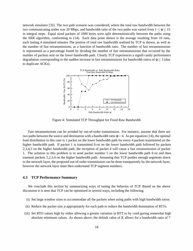
network simulator [35]. The two path scenario was considered, where the total raw bandwidth between thetwo communicating nodes was 20 Mbps, and bandwidth ratio of the two paths was varied from 1 ≤ φ ≤ 15in integral steps. Equal sized packets of 1000 bytes were split deterministically between the paths usingthe SRR algorithm, conforming to (14). Each data point shown is the average resulting from 10 runs,each lasting 4 simulated minutes The portion of total raw bandwidth realized by TCP is shown, as well asthe number of fast retransmissions, as a function of bandwidth ratio. The number of fast retransmissionsis represented as a percentage found by dividing the number of fast retransmissions that occurred by thenumber of packets sent on the lower bandwidth path. Clearly TCP experiences a significantly performancedegradation corresponding to the sudden increase in fast retransmissions for bandwidth ratios of φ ≥ 3 (dueto duplicate ACKs).
Fast RetransmissionsTCP Bandwidth
Total Raw Bandwidth 20 MbpsTCP Bandwidth vs. Path Bandwidth Ratio
Path Bandwidth Ratio φ
Ban
dwid
th/F
astR
eTX
(%)
1614121086420
100
80
60
40
20
0
Figure 4: Simulated TCP Throughput for Fixed Raw Bandwidth
Fast retransmissions can be avoided by out-of-order transmission. For instance, assume that there aretwo paths between the source and destination with a bandwidth ratio φ = 4. As per equation (14), the optimalload distribution in this case is 1 packet on the lower bandwidth path for every 4 packets transmitted on thehigher bandwidth path. If packet 1 is transmitted first on the lower bandwidth path followed by packets2,3,4,5 on the higher bandwidth path, the reception of packet 4 will cause a fast retransmission of packet1. The solution to this problem is to send packet number 5 on the lower bandwidth path first and thentransmit packets 1,2,3,4 on the higher bandwidth path. Assuming that TCP pushes enough segments downto the network layer, the proposed out-of-order transmission can be done transparently by the network layer,however the network layer must then understand TCP segment numbers.
4.3 TCP Performance Summary
We conclude this section by summarizing ways of tuning the behavior of TCP. Based on the abovediscussion it is seen that TCP can be optimized in several ways, including the following.
(i) Set large window sizes to accommodate all the packets when using paths with high bandwidth ratios.
(ii) Reduce the packet size p appropriately for each path to reduce the bandwidth domination of RTTs.
(iii) Set RTO values high by either allowing a greater variation in RTT or by configuring somewhat highabsolute minimum values. As shown above, the default value of K allows for a bandwidth ratio of 7
18

when equal sized packets are used. A value of K = 13 covers paths with bandwidth ratios up to 25.
(iv) Use TCP Vegas and other enhanced TCP versions that mitigate the effect of slow-start.
(v) Allow sending packets out-of-order to avoid fast retransmissions.
Note that all the above modifications and optimizations can be confined to the sender side alone. Theypreserve the end-to-end TCP semantics and will transparently inter-operate with any standard TCP receiver.
5 Implementation and Results
We have tested a proof-of-concept implementation where the sender and receiver were connected bytwo logical paths. We implemented the above mentioned tunneling mechanism on a FreeBSD sender andreceiver. The dummynet facility [36] was used in our experiments. This allows the kernel to route packetsthrough logical paths based on specified probabilities.
For our experiments, we created two logical paths over a single physical path. We would like to em-phasize that it would be just as easy to run the experiment across two different physical paths. The logicalimplementation we chose offered a greater flexibility in controlling both the bandwidth of each path and theprobabilities with which each path was chosen, which in turn determined packet load distribution.
The firewalling mechanisms provided by FreeBSD were exploited on the sending side to set the propersource address for each packet and to encapsulate packets going through one of the paths. In this case equalsized 1500 byte packets were split probabilistically between the two paths. Similarly, the receiving side wasconfigured to strip encapsulating headers as needed. Further details regarding the experimental setup havebeen omitted for the sake of brevity.
The experimental results are illustrated in Figure 5(a) and Figure 5(b). These Figures show TCP band-width as a function of the raw bandwidth, which refers to the total bandwidth of both paths between thesource and the destination. TCP bandwidth was measured using the netperf benchmarking package [37].
Figure 5(a) shows the case when both paths have equal bandwidths. The three curves illustrate thebandwidth TCP achieves as a percentage of the total raw bandwidth available when only one path is used,when both paths are used without tunneling, and when both paths are used with tunneling. As expected,over several orders of magnitude, TCP realizes roughly twice the bandwidth when both paths are used si-multaneously compared to when only a single path is used. The similarity of the with and without tunnelingcurves shows that the impact of tunneling on TCP performance is negligible. Since a standard TCP con-nection is equivalent to using only a single path, this demonstrates that the proposed bandwidth aggregationmechanism can, in principle, deliver additional bandwidth to the application level.
To test the efficacy of the proposed mechanism we carried out experiments on two paths having differentbandwidths. As per the previous analysis for bandwidth dominated paths that have disparate bandwidths,the default value of K = 4 in most TCP implementations will ideally allow connection striping across pathswith bandwidth ratio of φ < 7 without incurring timeouts. For our experiments we selected a bandwidthratio of φ = 3 in order to have a reasonable difference in path bandwidths while at the same time pushing theupper limit of the default tolerance for duplicate ACKs before fast retransmissions might occur. The resultsare illustrated in Figure 5(b), with the curves being analogous to those in Figure 5(a).
19

Both Paths Used With TunnelingBoth Paths Used Without TunnelingOnly One Path Used
Path Bandwidth Ratio φ = 1TCP Bandwidth vs. Raw Bandwidth
Total Raw Bandwidth (Mbps)
TC
PB
andw
idth
(%)
1010.10.01
100
80
60
40
20
0
(a) Equal Bandwidth Paths
Both Paths Used With Tunneling
Both Paths Used Without Tunneling
Only Lower BW Path Used
Only Larger BW Path Used
Path Bandwidth Ratio φ = 3TCP Bandwidth vs. Raw Bandwidth
Total Raw Bandwidth (Mbps)
TC
PB
andw
idth
(%)
1010.10.01
100
80
60
40
20
0
(b) Bandwidth Ratio φ = 3
Figure 5: TCP Throughput for Fixed Bandwidth Ratios
The data shows that despite a 3:1 bandwidth disparity, simultaneous use of both paths can yield betterperformance. For data points at low raw bandwidth values, about 3 Mbps and below, some timeouts dooccur which is consistent with the data from Figure 2(a). This result is due to the probabilistic splitting andthe effect of using smoothed RTTs as previously explained. The timeouts do cause the lower bandwidthpath to drag down the higher bandwidth path somewhat.
For raw bandwidths above about 3 Mbps, the RTTs of both paths drop to sufficiently low values, whichin turn causes the RTO values to drop below 1 second. The version of the FreeBSD kernel used for theseexperiments imposed a lower limit of 1 second for RTO, below which timeouts will not occur. Note thatthe paths are still bandwidth dominated, i.e. the RTT values are still dominated by the bandwidth, but thetimeout values are now sufficiently large to accommodate the variation in RTT, which prevents timeouts.The net result is that the connection striping across two paths provides higher bandwidth than using thehigher bandwidth path by itself, demonstrating that the proposed mechanism works even for bandwidthdominated paths, as long as TCP timeouts can be mitigated.
To further investigate the limitations of our bandwidth aggregation scheme, TCP performance was in-vestigated over a range of bandwidth ratios while the total raw bandwidth available was held constant.These experiments were again performed with two network paths between communicating hosts, howevertunneling was omitted since its impact is negligible. This time equal sized 1500 byte packets were splitdeterministically between the two paths. The results are shown in Figure 6(a) and Figure 6(b). Both plotsshow the TCP bandwidth achieved when both paths are used, and when only the higher bandwidth path isused alone. These results agree closely with (51) and Figure 3(a), showing that a bandwidth ratio of around4 can be tolerated when deterministic packet splitting is employed.
20

Only Larger BW Path UsedBoth Paths Used
Total Raw Bandwidth 2 MbpsTCP Bandwidth vs. Path Bandwidth Ratio
Path Bandwidth Ratio φ
TC
PB
andw
idth
(%)
1614121086420
100
80
60
40
20
0
(a) 2 Mbps Total Raw Bandwidth
Only Larger BW Path UsedBoth Paths Used
Total Raw Bandwidth 20 MbpsTCP Bandwidth vs. Path Bandwidth Ratio
Path Bandwidth Ratio φ
TC
PB
andw
idth
(%)
1614121086420
100
80
60
40
20
0
(b) 20 Mbps Total Raw Bandwidth
Figure 6: TCP Throughput for Fixed Raw Bandwidth
6 Conclusions
We have proposed a novel mechanism to stream data simultaneously across multiple IP paths in order toaggregate their bandwidth. It is applicable to connectionless (UDP) flows as well as for striping the data flowin a TCP connection across multiple IP paths. We investigated its performance and experimentally validatedthe analytical results. The work was motivated by practical considerations. As ubiquitous network access isbecoming a reality the number of wireless data transmission technologies continues to grow. It is thereforeclear that in the near future, there will be multiple transport conduits. Our analysis and data demonstratethat the proposed mechanism works well in most such scenarios of practical interest.
Future work includes an implementation of all the TCP modifications and optimizations mentionedabove and more detailed simulations in wireless and mobile scenarios. Another approach is to implement theload sharing capability in SCTP and compare it with the mechanism proposed herein. Lastly, dynamicallyadding or deleting IP addresses from a connection involving end-points with multiple interfaces could leadto security hazards which warrant further investigation.
References
[1] G. Malkin, Nortel Networks Multi-link Multi-node PPP Bundle Discovery Protocol, September 1999.RFC 2701.
[2] K. Sklower, B. Lloyd, G. McGregor, D. Carr, and T. Coradetti, The PPP Multilink Protocol (MP),August 1996. RFC 1990.
[3] K. Sklower, B. Lloyd, G. McGregor, and D. Carr, The PPP Multilink Protocol (MP), November 1994.RFC 1717.
[4] E. W. Simpson, The Point-to-Point Protocol (PPP), July 1994. RFC 1661.
[5] E. W. Simpson, PPP in HDLC-like Framing, July 1994. RFC 1662.
21

[6] D. Rand, PPP Reliable Transmission, July 1994. RFC 1663.
[7] R. Ogier, V. Ruenburg, and N. Shacham, “Distributed algorithms for computing shortest pairs of dis-joint paths,” IEEE Transactions on Information Theory, vol. 39, pp. 443–455, Mar. 1993.
[8] I. Cidon, R. Rom, and Y. Shavim, “Analysis of multi-path routing,” IEEE/ACM Transactions on Net-working, vol. 7, pp. 885–896, Dec. 1999.
[9] N. Taft-Plotkin, B. Bellur, and R. Ogier, “Quality of Service Routing Using Maximally Disjoint Paths,”in Proceedings of the IEEE IWQoS’99, London, UK., pp. 119–128, June 1999.
[10] A. Nasipuri and S. R. Das, “On-Demand Multipath Routing for Ad-Hoc Networks,” in Proceedings ofthe IEEE ICCCN,99, Boston, pp. 64–70, October 1999.
[11] J. Raju and J. Garcia-Luna-Aceves, “A New Approach to On-Demand Multipath Routing,” in Pro-ceedings of the IEEE ICCCN,99, Boston, pp. 522–527, October 1999.
[12] M. Pearlman, Z. Haas, P. Scholander, and S. Tabrizi, “On the Impact of Alternate Path Routing for LoadBalancing in Mobile Ad Hoc Networks,” in Proceedings of ACM MobiHOC’00, Boston, pp. 119–128,August 2000.
[13] M. G. Sung-Ju Lee, “Split Multipath Routing with Maximally Disjoint Paths in Ad hoc Networks ,” inProceedings of ICC’01, Helsinki, Finland, June 2001.
[14] W-H Liao et. al., “A Multi-Path QoS Routing Protocol in a Wireless Mobile Ad Hoc Network,” inProceedings of the IEEE ICN’00, CREF, Colmar, France, July 2001.
[15] A. Snoeren, “Adaptive Inverse Multiplexing for Wide-Area Wirelss Networks,” in IEEE Globecom,pp. 1665–1672, 1999.
[16] H. Adiseshu and G. Parulkar and G. Varghese, “A Reliable and Scalable Striping Protocol,” in ACMSIGCOMM, pp. 131–141, 1996.
[17] D. C. Anderson, J. S. Chase, and A. M. Vahdat, “Interposed request routing for scalable networkstorage,” in Proceedings of the Fourth Symposium on Operating System Design and Implementation(OSDI), October 2000.
[18] Sun Microsystems, “Sun StorEdge Network Data Replicator White Paper.”http://www.sun.com/storage/white-papers/sndr.html.
[19] A. Watson, Network Appliance, Inc., “Filer Deployment Strategies for Evolving LAN Topologies.”http://www.netapp.com/tech_library/3009.html.
[20] R. Haagens, “iSCSI requirements.”http://www.ietf.org/proceedings/00jul/SLIDES/ips-iscsi-reqs.pdf.
[21] Cisco Systems, “Etherchannel technologies.”http://www.cisco.com/warp/public/779/largeent/learn/technologies/fast_echannel.html.
[22] “SCTP Reference Implementation.” http://www.sctp.org/.
[23] “GPL SCTP Prototype Implementation.” www.sctp.de/.
[24] “SCTP for beginners.” http://tdrwww.exp-math.uni-essen.de/pages/forschung/sctp_fb.
[25] “SCTP: An Overview.” http://sctp.chicago.il.us/sctpoverview.html.
[26] “Protocol Engineering Lab at University of Delaware CIS Dept.”http://www.cis.udel.edu/˜iyengar/research/SCTP.
22

[27] R. R. Stewart, M. A. Ramalho et. al., “SCTP Extensions for Dynamic Reconfigu-ration of IP Addresses and Enforcement of Flow and Message Limits,” June 2001.http://www.ietf.org/internet-drafts/draft-ietf-tsvwg-addip-sctp-02.txt.
[28] E. C. Perkins, IP Mobility Support, October 1996. RFC 2002.
[29] C. Perkins, IP Encapsulation within IP, October 1996. RFC 2003.
[30] C. Perkins, Minimal Encapsulation within IP, October 1996. RFC 2004.
[31] J. Solomon, Applicability Statement for IP Mobility Support, October 1996. RFC 2005.
[32] V. Jacobson, “Modified TCP Congestion Avoidance Algorithm.” end2end interest group mailing list,April 1990.
[33] M. Shreedhar and G. Varghese, “Efficient fair queuing using deficit round robin,” in SIGCOMM: ACMSpecial Interest Group on Data Communication, (Cambridge, MA), pp. 231–242, September 1995.
[34] H. Adiseshu, G. Parulkar, and G. Varghese, “A reliable and scalable striping protocol,” in SIGCOMM:ACM Special Interest Group on Data Communication, (Palo Alto, CA), pp. 131–141, August 1996.
[35] S. McCanne and S. Floyd, “ns network simulator.” http://www.isi.edu/nsnam/ns/.
[36] L. Rizzo, “Dummynet: a simple approach to the evaluation of network protocols,” ACM ComputerCommunication Review, vol. 27, pp. 31–41, Jan. 1997.
[37] Information Networks Division, Hewlett–Packard Company, Netperf: A Network Performance Bench-mark, February 15 1996. http://www.netperf.org/.
23