ip enabled 21” 2 page / 8 channel color quad ... enabled 21” 2 page / 8 channel color quad...
TRANSCRIPT
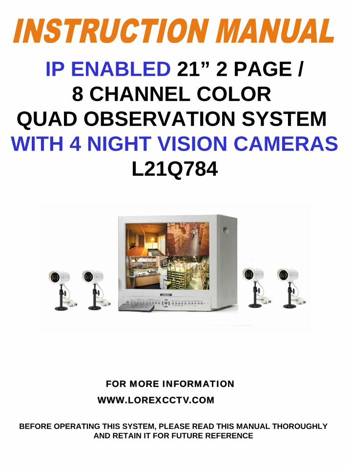
IP ENABLED 21” 2 PAGE /8 CHANNEL COLOR
QUAD OBSERVATION SYSTEM WITH 4 NIGHT VISION CAMERAS
L21Q784
BEFORE OPERATING THIS SYSTEM, PLEASE READ THIS MANUAL THOROUGHLYAND RETAIN IT FOR FUTURE REFERENCE
FOR MORE INFORMATION
WWW.LOREXCCTV.COM
Thank you for purchasing the IP Enabled 21” 2 Page/8 Channel Color Quad Observation System. LOREX is committed to providing our customers with a high quality, reliable security product that customers have come to expect from us.
The IP enabled Observation system allows you to make an ethernet LAN connection from the monitor to a computer for internet monitoring. With this 2 Page Quad system, you are capable of viewing up to 8 camera locations in real time. This system provides multiple viewing options including: Quad, Sequential, Selectable or Sequential Picture in Picture, Zoom, Freeze and full screen viewing options.
Connect a time lapse VCR to this system to record key events, or add additional cameras to view more locations.
To learn more about this 21” 2 Page/8 Channel Color Quad Observation system and to learn about our complete range of accessory products, please visit our website at:
www.lorexcctv.com
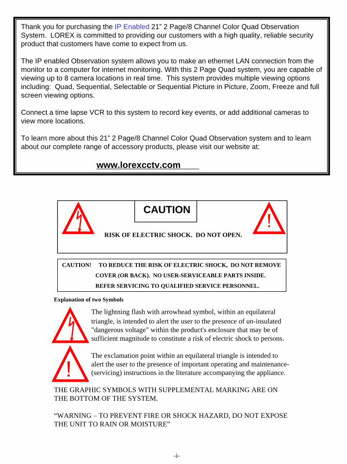
Explanation of two Symbols
The lightning flash with arrowhead symbol, within an equilateral triangle, is intended to alert the user to the presence of un-insulated "dangerous voltage" within the product's enclosure that may be of sufficient magnitude to constitute a risk of electric shock to persons.
The exclamation point within an equilateral triangle is intended toalert the user to the presence of important operating and maintenance-(servicing) instructions in the literature accompanying the appliance.
THE GRAPHIC SYMBOLS WITH SUPPLEMENTAL MARKING ARE ONTHE BOTTOM OF THE SYSTEM.
“WARNING – TO PREVENT FIRE OR SHOCK HAZARD, DO NOT EXPOSETHE UNIT TO RAIN OR MOISTURE”
CAUTION
RISK OF ELECTRIC SHOCK. DO NOT OPEN.
CAUTION! TO REDUCE THE RISK OF ELECTRIC SHOCK, DO NOT REMOVE
COVER (OR BACK). NO USER-SERVICEABLE PARTS INSIDE.
REFER SERVICING TO QUALIFIED SERVICE PERSONNEL.
!
!
-i-
NOTE
This equipment has been certified and found to comply with the limits regulated byFCC, EMC and LVD. Therefore, it is designed to provide reasonable protection against interference and will not cause interference with other appliance usage. However, it is imperative that user follows this manual's guidelines to avoid improperusage which may result in damage to the unit, electrical shock and fire hazard or injury.
In order to improve the feature functions and quality of this product, the specifications are subject to change without notice from time to time.
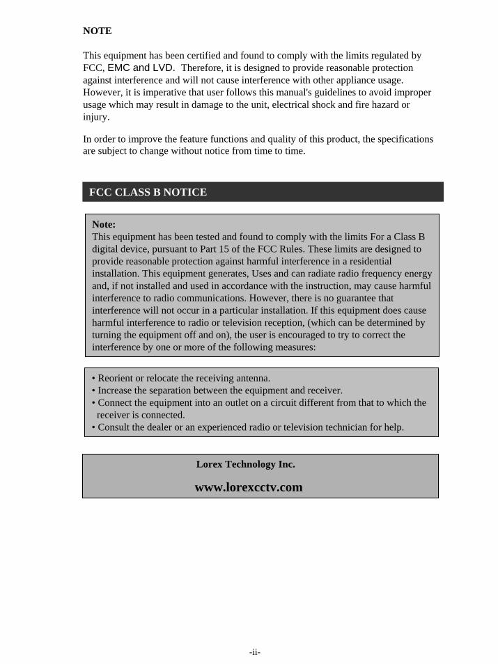
Note:This equipment has been tested and found to comply with the limits For a Class Bdigital device, pursuant to Part 15 of the FCC Rules. These limits are designed toprovide reasonable protection against harmful interference in a residential installation. This equipment generates, Uses and can radiate radio frequency energyand, if not installed and used in accordance with the instruction, may cause harmfulinterference to radio communications. However, there is no guarantee thatinterference will not occur in a particular installation. If this equipment does causeharmful interference to radio or television reception, (which can be determined byturning the equipment off and on), the user is encouraged to try to correct the interference by one or more of the following measures:
• Reorient or relocate the receiving antenna.• Increase the separation between the equipment and receiver.• Connect the equipment into an outlet on a circuit different from that to which the
receiver is connected.• Consult the dealer or an experienced radio or television technician for help.
FCC CLASS B NOTICE
Lorex Technology Inc.
www.lorexcctv.com
-ii-
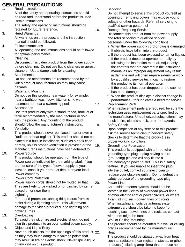
GENERAL PRECAUTIONS:1. Read Instructions
All of the safety and operating instructions shouldbe read and understood before the product is used.
2. Retain InstructionsThe safety and operating instructions should be retained for future reference.
3. Heed WarningsAll warnings on the product and the instruction manual should be followed.
4. Follow InstructionsAll operating and use instructions should be followedfor optimal performance
5. CleaningDisconnect this video product from the power supplybefore cleaning. Do not use liquid cleaners or aerosolcleaners. Use a damp cloth for cleaning.
6. AttachmentsDo not use attachments not recommended by thevideo product manufacturer as they may causehazards.
7. Water and MoistureDo not use this product near water - for example,near a bathtub, wash bowl, kitchen sink, wet basement, or near a swimming pool.
8. AccessoriesUse this product only with a stand, tripod, bracket ortable recommended by the manufacturer or soldwith the product. Any mounting of the product should follow the manufacturer’s instructions.
9. VentilationThis product should never be placed near or over a Radiator or heat register. This product should not beplaced in a built-in installation, such as a book caseor rack, unless proper ventilation is provided or theManufacturer’s instructions have been adhered to.
10. Power SourceThis product should be operated from the type of Power source indicated by the marking label. If youare not sure of the type of power supply to your location, consult your product dealer or your local Power company
11. Power Cord ProtectionPower supply cords should not be routed so that They are likely to be walked on or pinched by itemsplaced on or near them
12. LightningFor added protection, unplug this product from its outlet during a lightning storm. This will preventdamage to the video product due to lightning andpower surges
13. OverloadingTo avoid the risk of fire and electric shock, do not plug this product into an over-loaded power supply.
14. Object and Liquid EntryNever push objects into the openings of this productas they may touch dangerous voltage points thatmay result in fire or electric shock. Never spill a liquidof any kind on this product.
15. ServicingDo not attempt to service this product yourself as opening or removing covers may expose you tovoltage or other hazards. Refer all servicing toqualified service personnel
16. Damage Requiring ServiceDisconnect this product from the power supplyand refer servicing to qualified servicepersonnel under the following conditions:a. When the power supply cord or plug is damagedb. If objects have fallen into the productc. If the product has been exposed to rain or liquidsd. If the product does not operate normally by
following the instruction manual. Adjust onlythe controls that are covered in the instructionmanual as an improper adjustment may result in damage and will often require extensive workby a qualified service technician to restorethe product to its normal operation
e. If the product has been dropped or the cabinethas been damaged
f. When the product displays a distinct change inperformance - this indicates a need for service
17. Replacement PartsWhen replacement parts are required, be sure thetechnician uses replacement parts specified bythe manufacturer. Unauthorized substitutions mayresult in fire, electric shock, or other hazards.
18. Safety CheckUpon completion of any service to this productask the service technician to perform safetychecks to determine that the product is inproper working condition.
19. Grounding or PolarizationThis product is equipped with a three-wiregrounding-type plug, a plug having a third(grounding) pin and will only fit into a grounding-type power outlet. This is a safetyfeature. If you are unable to insert the pluginto the outlet, contact your electrician to replace your obsolete outlet. Do not defeat thesafety purpose of the grounding-type plug.
20. Power LinesAn outside antenna system should not be located in the vicinity of overhead power linesor other electric light or power circuits, or whereit can fall into such power lines or circuits. When installing an outside antenna system, extreme care should be taken to keep fromtouching such power lines or circuits as contactwith them might be fatal.
21. Wall or Ceiling MountingThe product should be mounted to a wall or ceiling only as recommended by the manufacturer.
22. HeatThe product should be situated away from heat such as radiators, hear registers, stoves, or other products (including amplifiers) that produce heat.
-2-
CONTENTS:
-1-
1. CAUTIONS AND FEATURES ------------------------------------------------------------------ 3
2. SYSTEM --------------------------------------------------------------------------------------------- 4
3. MONITOR CONTROLS - FRONT PANEL -------------------------------------------------- 5
4. MAIN MENU CONTROL ------------------------------------------------------------------------ 9
5. MONITOR CONTROLS - BACK PANEL ---------------------------------------------------- 12
6. REMOTE CONTROL --------------------------------------------------------------------------- 13
7. STANDARD WIRED CAMERA & CAMERA INSTALLATION ----------------------- 14
8. MONITOR CONNECTIONS & TROUBLE SHOOTING ------------------------------- 15
9. TECHNICAL SPECIFICATIONS ------------------------------------------------------------ 16
10. OPTIONAL ACCESSORIES ----------------------------------------------------------------- 17
11. APPENDIX A – CONNECTING MONITOR TO A STANDARD VCR ------------------------------------------------------------------------------- 18
12. APPENDIX B - CONNECTING TO A SLAVE MONITOR ----------------------------- 19
13. APPENDIX C - CONNECTING TO A LOREX TIME LAPSE VCRFOR ALARM RECORDING ------------------------------------------------------------------- 20
14. CARE AND MAINTENANCE ------------------------------------------------------------------ 21
1. All the warnings and instructions of this manual should be followed
2. Remove the plug from the outlet before cleaning. Do not use liquid aerosol detergents. Usewater damped cloth for cleaning
3. Do not use this unit in very humid and wet places
4. Keep enough space around the unit for ventilation. Slots and openings of the cabinet shouldnot be blocked.
5. During flashes of lightning or cracks of thunder, or when the system is not used for a long time,unplug the system power supply and disconnect the antenna and cables to protect the unitfrom lightening or power surges.
Monitor Features:
• Built-in integrated IP Server for Internet Monitoring (software included)• View up to 8 camera locations in real time• Metal cabinet with 8 camera inputs (8 DIN / 8 BNC and 8 audio RCA)• 2 way audio• Single or Dual PIP viewing options – main and PIP channels• Selectable POP viewing options• Selectable still frame in quad or full screen• Two times zoom• Motion Sensing Alarm Function• Video loss detection warning (only on active page shown on screen)• On screen viewing: date*time*camera• Remote control or main panel operation• ON/OFF standby switch enables monitor screen to be turned off while recording• Multi-voltage system 100 – 240Volts
Standard Camera Features
• 1/4” CCD Color Camera with night vision• Built in speaker and microphone to allow for two way audio communication• Metal mounting bracket
CAUTIONS:
-3-
FEATURES:
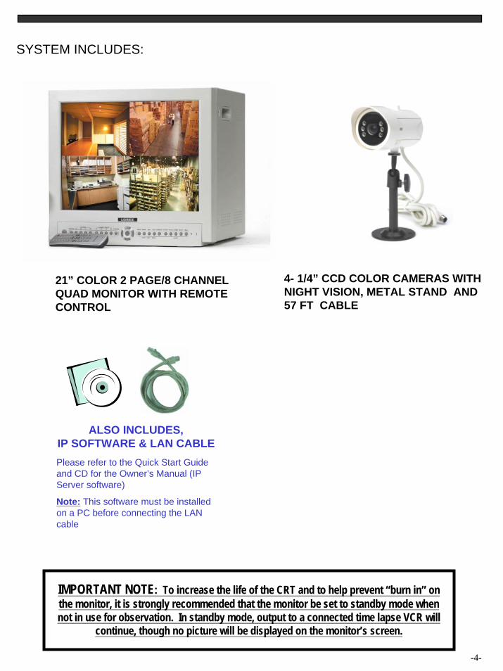
SYSTEM INCLUDES:
21” COLOR 2 PAGE/8 CHANNELQUAD MONITOR WITH REMOTE CONTROL
4- 1/4” CCD COLOR CAMERAS WITH NIGHT VISION, METAL STAND AND57 FT CABLE
-4-
IMPORTANT NOTE: To increase the life of the CRT and to help prevent “burn in” on the monitor, it is strongly recommended that the monitor be set to standby mode when not in use for observation. In standby mode, output to a connected time lapse VCR will
continue, though no picture will be displayed on the monitor’s screen.
ALSO INCLUDES,IP SOFTWARE & LAN CABLEPlease refer to the Quick Start Guide and CD for the Owner’s Manual (IP Server software)
Note: This software must be installed on a PC before connecting the LAN cable
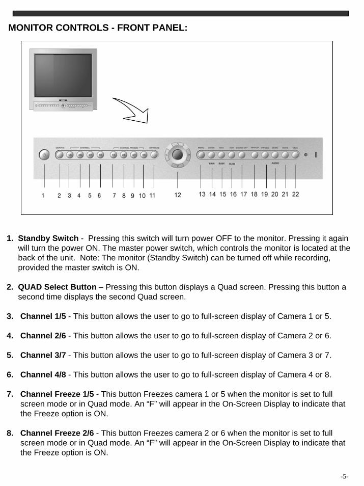
MONITOR CONTROLS - FRONT PANEL:
-5-
1. Standby Switch - Pressing this switch will turn power OFF to the monitor. Pressing it againwill turn the power ON. The master power switch, which controls the monitor is located at the back of the unit. Note: The monitor (Standby Switch) can be turned off while recording, provided the master switch is ON.
2. QUAD Select Button – Pressing this button displays a Quad screen. Pressing this button a second time displays the second Quad screen.
3. Channel 1/5 - This button allows the user to go to full-screen display of Camera 1 or 5.
4. Channel 2/6 - This button allows the user to go to full-screen display of Camera 2 or 6.
5. Channel 3/7 - This button allows the user to go to full-screen display of Camera 3 or 7.
6. Channel 4/8 - This button allows the user to go to full-screen display of Camera 4 or 8.
7. Channel Freeze 1/5 - This button Freezes camera 1 or 5 when the monitor is set to full screen mode or in Quad mode. An “F” will appear in the On-Screen Display to indicate thatthe Freeze option is ON.
8. Channel Freeze 2/6 - This button Freezes camera 2 or 6 when the monitor is set to full screen mode or in Quad mode. An “F” will appear in the On-Screen Display to indicate thatthe Freeze option is ON.
9. Channel Freeze 3/7 - This button Freezes camera 3 or 7 when the monitor is set to full screen mode or in Quad mode. An “F” will appear in the On-Screen Display to indicate that the Freeze option is ON.
10. Channel Freeze 4/8 - This button Freezes camera 4 or 8 when the monitor is set to full screen mode or in Quad mode. An “F” will appear in the On-Screen Display to indicate thatthe Freeze option is ON.
11. Screen Freeze - This button Freezes whichever screen you are viewing when you press it. If you set the Screen Freeze in Quad mode, all four cameras will be “frozen”. An “F” will appear in the On-Screen Display.
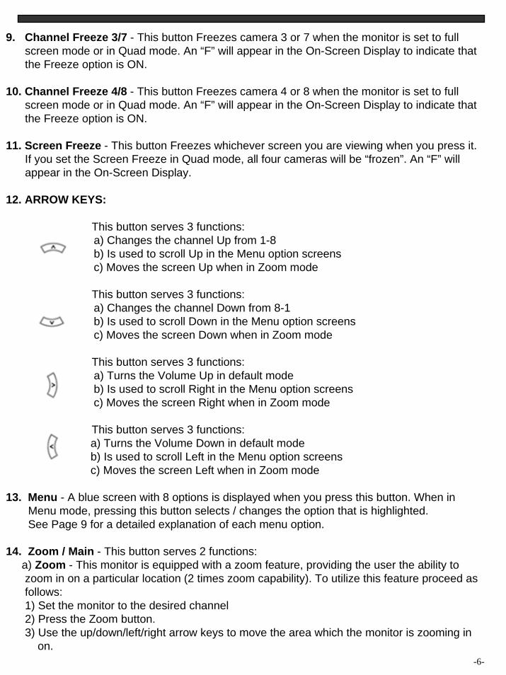
12. ARROW KEYS:
This button serves 3 functions:a) Changes the channel Up from 1-8b) Is used to scroll Up in the Menu option screensc) Moves the screen Up when in Zoom mode
This button serves 3 functions:a) Changes the channel Down from 8-1b) Is used to scroll Down in the Menu option screensc) Moves the screen Down when in Zoom mode
This button serves 3 functions:a) Turns the Volume Up in default modeb) Is used to scroll Right in the Menu option screensc) Moves the screen Right when in Zoom mode
This button serves 3 functions:a) Turns the Volume Down in default modeb) Is used to scroll Left in the Menu option screensc) Moves the screen Left when in Zoom mode
13. Menu - A blue screen with 8 options is displayed when you press this button. When in Menu mode, pressing this button selects / changes the option that is highlighted. See Page 9 for a detailed explanation of each menu option.
14. Zoom / Main - This button serves 2 functions:a) Zoom - This monitor is equipped with a zoom feature, providing the user the ability tozoom in on a particular location (2 times zoom capability). To utilize this feature proceed as follows:1) Set the monitor to the desired channel2) Press the Zoom button.3) Use the up/down/left/right arrow keys to move the area which the monitor is zooming in
on.-6-
4) To exit Zoom Mode, press the Zoom button once again.Note: the Zoom function is available in PIP/POP mode by holding the Zoom button for 3seconds.
b) Main - Another function of the Zoom/Main button that is used in PIP/POP mode. Refer tothe PIP/POP section below for an explanation.
15. Sequence / Sub1a) Sequence - used to sequence between all camera locations in full screen in sequentialorder with the screen changing every 2 seconds. The letters SEQ will appear in the on-screen display during sequencing. To change Sequence settings, refer to Page 9.Note: the Sequence function is available in PIP/POP mode by holding the Sequence button for 3 seconds.b) Sub1 - Used in PIP/POP mode. Refer to PIP/POP explanation below.
16. VCR / Sub2a) VCR - This button will change the display from the camera inputs to the VCR Audio/Video playback and recording signal. To return to the previous screen, press VCR again.Note: the VCR function is available in PIP/POP mode by holding the VCR button for 3 sec.b) Sub2 - Used in PIP/POP mode. Refer to PIP/POP explanation below
17. Alarm Off - This button turns off the alarm sound and sets the system to the previous mode.
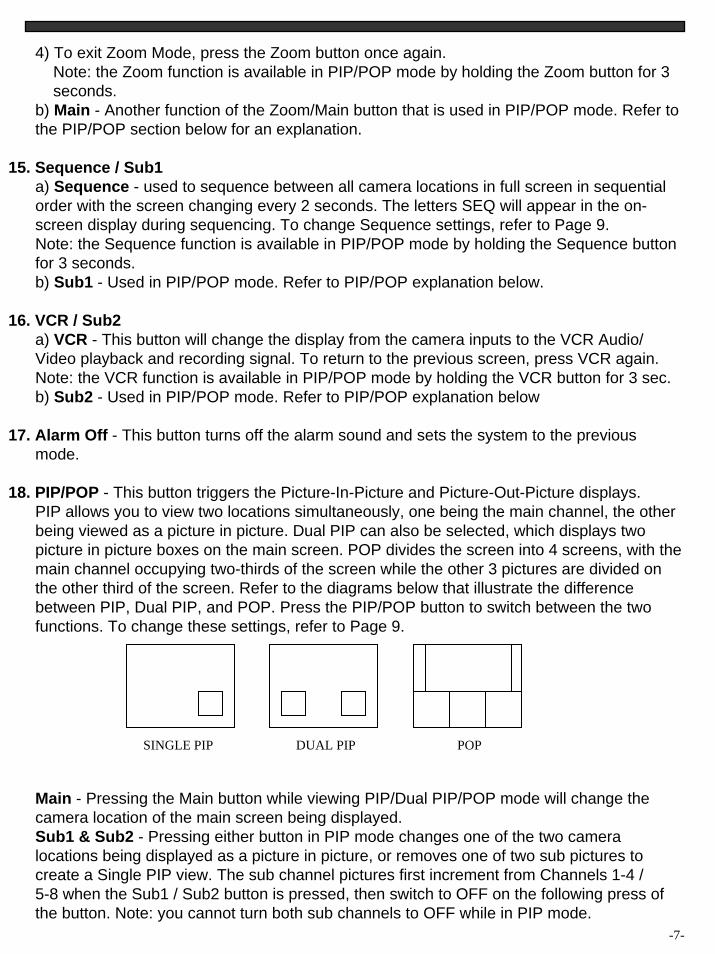
18. PIP/POP - This button triggers the Picture-In-Picture and Picture-Out-Picture displays.PIP allows you to view two locations simultaneously, one being the main channel, the otherbeing viewed as a picture in picture. Dual PIP can also be selected, which displays two picture in picture boxes on the main screen. POP divides the screen into 4 screens, with the main channel occupying two-thirds of the screen while the other 3 pictures are divided onthe other third of the screen. Refer to the diagrams below that illustrate the differencebetween PIP, Dual PIP, and POP. Press the PIP/POP button to switch between the twofunctions. To change these settings, refer to Page 9.
Main - Pressing the Main button while viewing PIP/Dual PIP/POP mode will change the camera location of the main screen being displayed.Sub1 & Sub2 - Pressing either button in PIP mode changes one of the two cameralocations being displayed as a picture in picture, or removes one of two sub pictures tocreate a Single PIP view. The sub channel pictures first increment from Channels 1-4 / 5-8 when the Sub1 / Sub2 button is pressed, then switch to OFF on the following press ofthe button. Note: you cannot turn both sub channels to OFF while in PIP mode.
-7-
SINGLE PIP DUAL PIP POP
19. PIP Sequence – Pressing this button initiates Sequencing in Single PIP mode. Pressingthis button a second time changes the channel of the fixed screen in PIP Sequencing. Toexit PIP Sequencing, press the PIP/POP button.You can program whether the Main picture or the Sub picture switches during PIPSequencing via the Menu. Please refer to page 9 for more details.
20. Audio / Demo – This button serves two functions.a) Audio - In Quad mode, the user can select the channel with audio. Pressing this button automatically changes the audio from camera to camera.b) Demonstration – Holding the Audio/Demo button for 3 seconds starts a sequencingthrough all the channels using different functions. Firstly the Quad screens are displayed,followed by full-screens, PIP/POP, Freeze, then Zoom. The word DEMO will appear in the top-right corner of the screen. To exit Demo mode, hold the Demo button for 3 seconds.
21. Mute - This button cuts off the Volume. To turn the Volume back on, press the button again.
22. Talk - By pressing and holding this button the user has the ability to talk to a specificcamera location. This button must be pressed the entire time, while talking. To listen to the camera location release the Talk button.
-8-
MAIN MENU CONTROL
The Main Menu is pulled up by pressing the Menu button. Scroll up and down through the eightoptions by pressing the and arrow keys. To enter a sub-menu, press the Menu button where the highlighted scroll bar is located. To exit the Main Menu, scroll down to the Exit option and press Menu. Note: in submenus of the Main Menu, you can either exit Menu mode entirely by selecting Exit, or you can return to the Main Menu by selecting Return.
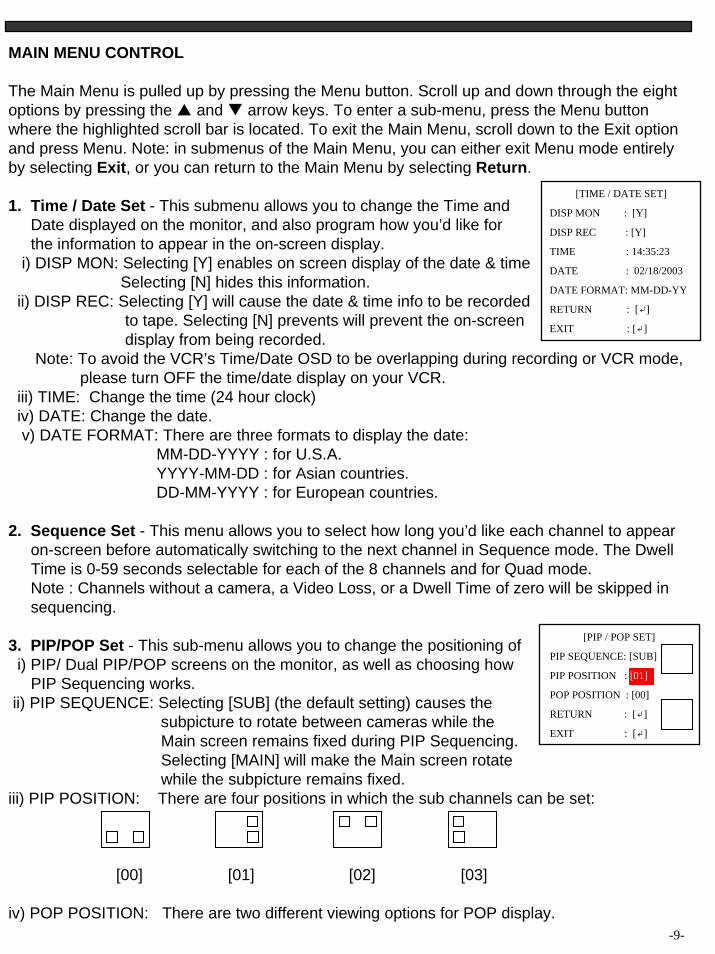
1. Time / Date Set - This submenu allows you to change the Time and Date displayed on the monitor, and also program how you’d like for the information to appear in the on-screen display.
i) DISP MON: Selecting [Y] enables on screen display of the date & timeSelecting [N] hides this information.
ii) DISP REC: Selecting [Y] will cause the date & time info to be recordedto tape. Selecting [N] prevents will prevent the on-screen display from being recorded.
Note: To avoid the VCR’s Time/Date OSD to be overlapping during recording or VCR mode,please turn OFF the time/date display on your VCR.
iii) TIME: Change the time (24 hour clock)iv) DATE: Change the date.v) DATE FORMAT: There are three formats to display the date:
MM-DD-YYYY : for U.S.A.YYYY-MM-DD : for Asian countries.DD-MM-YYYY : for European countries.
2. Sequence Set - This menu allows you to select how long you’d like each channel to appear on-screen before automatically switching to the next channel in Sequence mode. The DwellTime is 0-59 seconds selectable for each of the 8 channels and for Quad mode.Note : Channels without a camera, a Video Loss, or a Dwell Time of zero will be skipped insequencing.
3. PIP/POP Set - This sub-menu allows you to change the positioning of i) PIP/ Dual PIP/POP screens on the monitor, as well as choosing how
PIP Sequencing works.ii) PIP SEQUENCE: Selecting [SUB] (the default setting) causes the
subpicture to rotate between cameras while the Main screen remains fixed during PIP Sequencing.Selecting [MAIN] will make the Main screen rotatewhile the subpicture remains fixed.
iii) PIP POSITION: There are four positions in which the sub channels can be set:
[00] [01] [02] [03]
iv) POP POSITION: There are two different viewing options for POP display.-9-
[TIME / DATE SET]
DISP MON : [Y]
DISP REC : [Y]
TIME : 14:35:23
DATE : 02/18/2003
DATE FORMAT: MM-DD-YY
RETURN : [↲]
EXIT : [↲]
[PIP / POP SET]
PIP SEQUENCE: [SUB]
PIP POSITION : [01]
POP POSITION : [00]
RETURN : [↲]
EXIT : [↲]
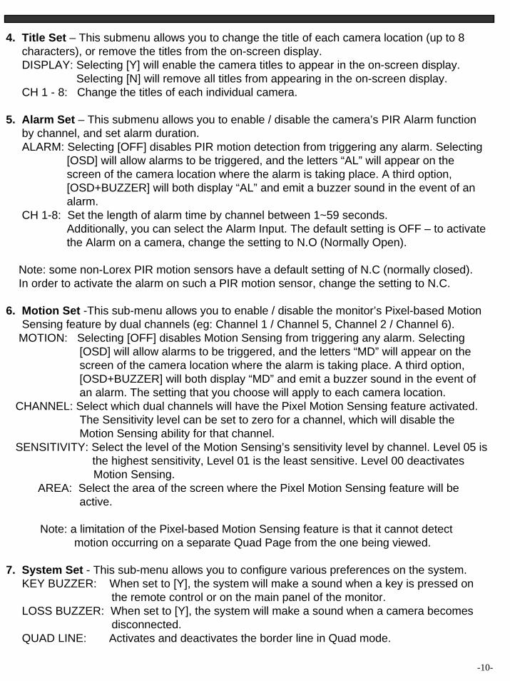
4. Title Set – This submenu allows you to change the title of each camera location (up to 8 characters), or remove the titles from the on-screen display.DISPLAY: Selecting [Y] will enable the camera titles to appear in the on-screen display.
Selecting [N] will remove all titles from appearing in the on-screen display.CH 1 - 8: Change the titles of each individual camera.
5. Alarm Set – This submenu allows you to enable / disable the camera’s PIR Alarm function by channel, and set alarm duration.ALARM: Selecting [OFF] disables PIR motion detection from triggering any alarm. Selecting
[OSD] will allow alarms to be triggered, and the letters “AL” will appear on the screen of the camera location where the alarm is taking place. A third option,[OSD+BUZZER] will both display “AL” and emit a buzzer sound in the event of analarm.
CH 1-8: Set the length of alarm time by channel between 1~59 seconds.Additionally, you can select the Alarm Input. The default setting is OFF – to activatethe Alarm on a camera, change the setting to N.O (Normally Open).
Note: some non-Lorex PIR motion sensors have a default setting of N.C (normally closed). In order to activate the alarm on such a PIR motion sensor, change the setting to N.C.
6. Motion Set -This sub-menu allows you to enable / disable the monitor’s Pixel-based Motion Sensing feature by dual channels (eg: Channel 1 / Channel 5, Channel 2 / Channel 6).
MOTION: Selecting [OFF] disables Motion Sensing from triggering any alarm. Selecting [OSD] will allow alarms to be triggered, and the letters “MD” will appear on the screen of the camera location where the alarm is taking place. A third option,[OSD+BUZZER] will both display “MD” and emit a buzzer sound in the event ofan alarm. The setting that you choose will apply to each camera location.
CHANNEL: Select which dual channels will have the Pixel Motion Sensing feature activated.The Sensitivity level can be set to zero for a channel, which will disable theMotion Sensing ability for that channel.
SENSITIVITY: Select the level of the Motion Sensing’s sensitivity level by channel. Level 05 is the highest sensitivity, Level 01 is the least sensitive. Level 00 deactivates Motion Sensing.
AREA: Select the area of the screen where the Pixel Motion Sensing feature will beactive.
Note: a limitation of the Pixel-based Motion Sensing feature is that it cannot detect motion occurring on a separate Quad Page from the one being viewed.
7. System Set - This sub-menu allows you to configure various preferences on the system.KEY BUZZER: When set to [Y], the system will make a sound when a key is pressed on
the remote control or on the main panel of the monitor.LOSS BUZZER: When set to [Y], the system will make a sound when a camera becomes
disconnected.QUAD LINE: Activates and deactivates the border line in Quad mode.
-10-
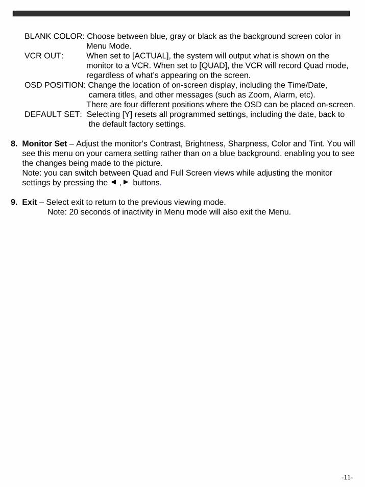
BLANK COLOR: Choose between blue, gray or black as the background screen color in Menu Mode.
VCR OUT: When set to [ACTUAL], the system will output what is shown on the monitor to a VCR. When set to [QUAD], the VCR will record Quad mode, regardless of what’s appearing on the screen.
OSD POSITION: Change the location of on-screen display, including the Time/Date, camera titles, and other messages (such as Zoom, Alarm, etc).There are four different positions where the OSD can be placed on-screen.
DEFAULT SET: Selecting [Y] resets all programmed settings, including the date, back to the default factory settings.
8. Monitor Set – Adjust the monitor’s Contrast, Brightness, Sharpness, Color and Tint. You willsee this menu on your camera setting rather than on a blue background, enabling you to seethe changes being made to the picture.Note: you can switch between Quad and Full Screen views while adjusting the monitor settings by pressing the , buttons.
9. Exit – Select exit to return to the previous viewing mode.Note: 20 seconds of inactivity in Menu mode will also exit the Menu.
-11-
-12-
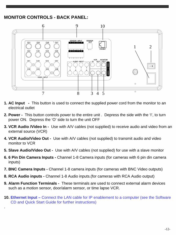
MONITOR CONTROLS - BACK PANEL:
1. AC Input - This button is used to connect the supplied power cord from the monitor to anelectrical outlet
2. Power - This button controls power to the entire unit . Depress the side with the ‘I’, to turn power ON. Depress the ‘O’ side to turn the unit OFF
3. VCR Audio /Video In - Use with A/V cables (not supplied) to receive audio and video from an external source (VCR)
4. VCR Audio/Video Out - Use with A/V cables (not supplied) to transmit audio and videomonitor to VCR
5. Slave Audio/Video Out - Use with A/V cables (not supplied) for use with a slave monitor
6. 6 Pin Din Camera Inputs - Channel 1-8 Camera inputs (for cameras with 6 pin din camera inputs)
7. BNC Camera Inputs - Channel 1-8 camera inputs (for cameras with BNC Video outputs)
8. RCA Audio inputs - Channel 1-8 Audio inputs.(for cameras with RCA Audio output)
9. Alarm Function Terminals - These terminals are used to connect external alarm devices such as a motion sensor, door/alarm sensor, or time lapse VCR.
10. Ethernet Input – Connect the LAN cable for IP enablement to a computer (see the SoftwareCD and Quick Start Guide for further instructions)
.
6
2
3 4 5
9
87
1
10
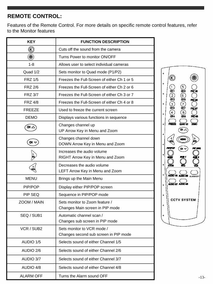
REMOTE CONTROL:Features of the Remote Control. For more details on specific remote control features, refer to the Monitor features
KEY FUNCTION DESCRIPTION
Cuts off the sound from the camera
Turns Power to monitor ON/OFF
1-8 Allows user to select individual cameras
Quad 1/2 Sets monitor to Quad mode (P1/P2)
FRZ 1/5 Freezes the Full-Screen of either Ch 1 or 5
FRZ 2/6 Freezes the Full-Screen of either Ch 2 or 6
FRZ 3/7 Freezes the Full-Screen of either Ch 3 or 7
FRZ 4/8 Freezes the Full-Screen of either Ch 4 or 8
FREEZE Used to freeze the current screen
DEMO Displays various functions in sequence
Changes channel upUP Arrow Key in Menu and Zoom
Changes channel downDOWN Arrow Key in Menu and Zoom
Increases the audio volumeRIGHT Arrow Key in Menu and Zoom
Decreases the audio volumeLEFT Arrow Key in Menu and Zoom
MENU Brings up the Main Menu
PIP/POP Display either PIP/POP screen
SEQ / SUB1 Automatic channel scan /Changes sub screen in PIP mode
VCR / SUB2 Sets monitor to VCR mode / Changes second sub screen in PIP mode
AUDIO 1/5 Selects sound of either Channel 1/5
AUDIO 2/6 Selects sound of either Channel 2/6
AUDIO 3/7 Selects sound of either Channel 3/7
AUDIO 4/8 Selects sound of either Channel 4/8
ALARM OFF Turns the Alarm sound OFF
PIP SEQ Sequence in PIP/POP mode
ZOOM / MAIN Sets monitor to Zoom feature / Changes Main screen in PIP mode
-13-
ALARM OFF
CCTV SYSTEM
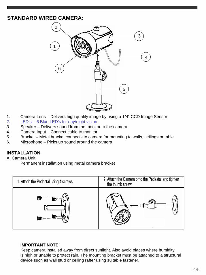
STANDARD WIRED CAMERA:
1. Camera Lens – Delivers high quality image by using a 1/4” CCD Image Sensor2. LED’s - 6 Blue LED’s for day/night vision3. Speaker – Delivers sound from the monitor to the camera4. Camera Input – Connect cable to monitor5. Bracket – Metal bracket connects to camera for mounting to walls, ceilings or table6. Microphone – Picks up sound around the camera
INSTALLATIONA. Camera Unit
Permanent installation using metal camera bracket
IMPORTANT NOTE:Keep camera installed away from direct sunlight. Also avoid places where humidityis high or unable to protect rain. The mounting bracket must be attached to a structuraldevice such as wall stud or ceiling rafter using suitable fastener.
-14-
1
3
4
5
6
2
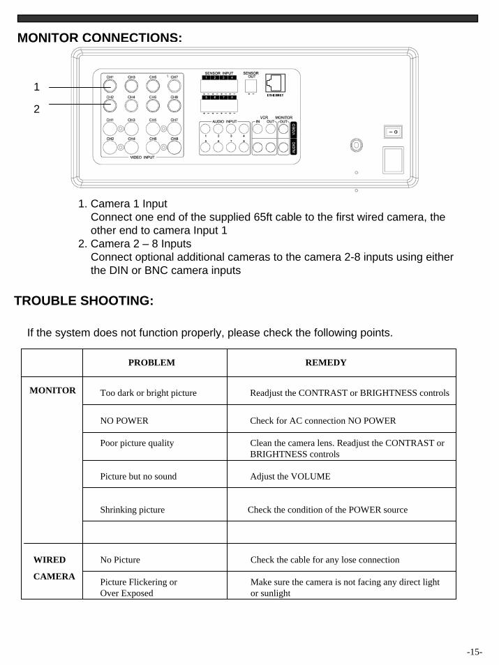
MONITOR CONNECTIONS:
1. Camera 1 InputConnect one end of the supplied 65ft cable to the first wired camera, the other end to camera Input 1
2. Camera 2 – 8 InputsConnect optional additional cameras to the camera 2-8 inputs using either the DIN or BNC camera inputs
-15-
If the system does not function properly, please check the following points.
TROUBLE SHOOTING:
MONITOR
PROBLEM REMEDY
Too dark or bright picture Readjust the CONTRAST or BRIGHTNESS controls
NO POWER Check for AC connection NO POWER
Poor picture quality Clean the camera lens. Readjust the CONTRAST or BRIGHTNESS controls
Picture but no sound Adjust the VOLUME
Shrinking picture Check the condition of the POWER source
No Picture
Picture Flickering orOver Exposed
Check the cable for any lose connection
Make sure the camera is not facing any direct light or sunlight
WIRED
CAMERA
1
2
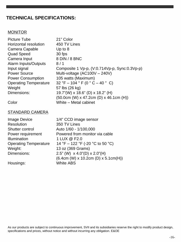
TECHNICAL SPECIFICATIONS:
MONITOR
Picture Tube 21” ColorHorizontal resolution 450 TV LinesCamera Capable Up to 8 Quad Speed 30 fpsCamera Input 8 DIN / 8 BNCAlarm Inputs/Outputs 8 / 1 Input signal Composite 1 Vp-p, (V:0.714Vp-p, Sync:0.3Vp-p)Power Source Multi-voltage (AC100V – 240V)Power Consumption 105 watts (Maximum)Operating Temperature 32 °F – 104 ° F (0 ° C – 40 ° C)Weight 57 lbs (26 kg)Dimensions: 19.7”(W) x 18.6” (D) x 18.2” (H)
(50.0cm (W) x 47.2cm (D) x 46.1cm (H))Color White – Metal cabinet
STANDARD CAMERA
Image Device 1/4” CCD image sensorResolution 350 TV LinesShutter control Auto 1/60 - 1/100,000Power requirement Powered from monitor via cableIllumination 1 LUX @ F2.0Operating Temperature 14 °F – 122 °F (-20 °C to 50 °C)Weight: 13 oz (369 Grams)Dimensions: 2.5” (W) x 4.0”(D) x 2.0”(H)
(6.4cm (W) x 10.2cm (D) x 5.1cm(H))Housings: White ABS
As our products are subject to continuous improvement, SVII and its subsidiaries reserve the right to modify product design,specifications and prices, without notice and without incurring any obligation. E&OE
-16-
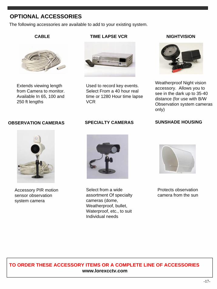
The following accessories are available to add to your existing system.
-17-
OPTIONAL ACCESSORIES
CABLE TIME LAPSE VCR
Extends viewing length from Camera to monitor. Available In 65, 100 and 250 ft lengths
Accessory PIR motion sensor observation system camera
Used to record key events. Select From a 40 hour real time or 1280 Hour time lapse VCR
SPECIALTY CAMERAS
NIGHTVISION
Weatherproof Night vision accessory. Allows you to see in the dark up to 35-40 distance (for use with B/WObservation system camerasonly)
Protects observation camera from the sun
Select from a wide assortment Of specialty cameras (dome, Weatherproof, bullet, Waterproof, etc., to suit Individual needs
TO ORDER THESE ACCESSORY ITEMS OR A COMPLETE LINE OF ACCESSORIESwww.lorexcctv.com
OBSERVATION CAMERAS SUNSHADE HOUSING
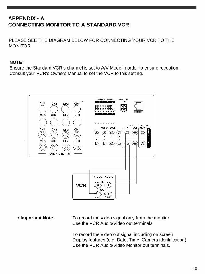
APPENDIX - ACONNECTING MONITOR TO A STANDARD VCR:
PLEASE SEE THE DIAGRAM BELOW FOR CONNECTING YOUR VCR TO THE MONITOR.
-18-
NOTE:Ensure the Standard VCR’s channel is set to A/V Mode in order to ensure reception.Consult your VCR’s Owners Manual to set the VCR to this setting.
• Important Note: To record the video signal only from the monitorUse the VCR Audio/Video out terminals.
To record the video out signal including on screenDisplay features (e.g. Date, Time, Camera identification)Use the VCR Audio/Video Monitor out terminals.
-19-
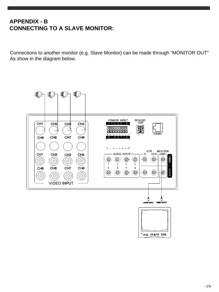
APPENDIX - BCONNECTING TO A SLAVE MONITOR:
Connections to another monitor (e.g. Slave Monitor) can be made through “MONITOR OUT”As show in the diagram below.
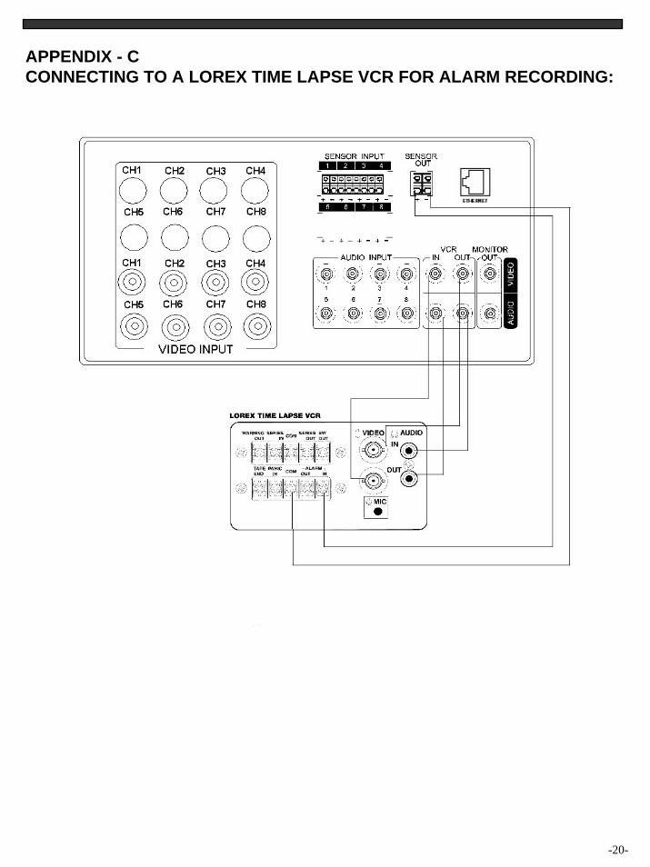
APPENDIX - CCONNECTING TO A LOREX TIME LAPSE VCR FOR ALARM RECORDING:
-20-
-21-
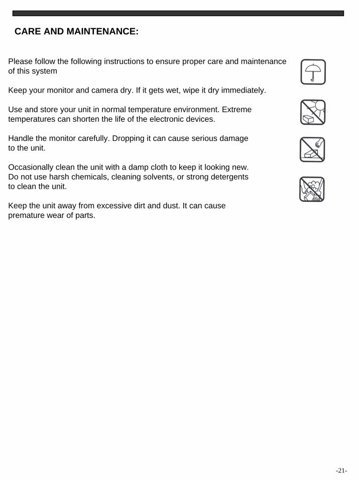
CARE AND MAINTENANCE:
Please follow the following instructions to ensure proper care and maintenanceof this system
Keep your monitor and camera dry. If it gets wet, wipe it dry immediately.
Use and store your unit in normal temperature environment. Extremetemperatures can shorten the life of the electronic devices.
Handle the monitor carefully. Dropping it can cause serious damageto the unit.
Occasionally clean the unit with a damp cloth to keep it looking new.Do not use harsh chemicals, cleaning solvents, or strong detergentsto clean the unit.
Keep the unit away from excessive dirt and dust. It can causepremature wear of parts.