ip converter product manual yt-940 series · - pisque potentiel de charge electrostatique. voir les...
TRANSCRIPT

IP Converter PRODUCT MANUAL YT-940 SERIES
VERSION 1.07

IP Converter YT-940 Product Manual
Ver. 1.07 2
Contents 1. Introduction ......................................................................................................................................... 3
1.1 General Information for the users .................................................................................................................... 3
1.2 Manufacturer Warranty .......................................................................................................................................... 3
1.3 Explosion Proof Warning & Specific Conditions of Use ......................................................................... 4
2. Product Description ............................................................................................................................ 5
2.1 General .......................................................................................................................................................................... 5
2.2 Main Features and Functions .............................................................................................................................. 5
2.4 Product Code .............................................................................................................................................................. 7
2.5 Product Specification .............................................................................................................................................. 8
2.6 Certifications ............................................................................................................................................................... 9
2.7 Parts, Assembly and Operation Logic ............................................................................................................ 10
2.8 Product Dimension ................................................................................................................................................. 11
2.8.1 YT-940 series .................................................................................................................................................. 11
2.8.2 YT-940 + YT-200 AFR directly mounted + Pressure gauge ........................................................ 11
3. Installation .......................................................................................................................................... 12
3.1 Safety and Installation Tips ................................................................................................................................ 12
4. Connection - Air ................................................................................................................................ 12
4.1 Safety ........................................................................................................................................................................... 12
4.2 Supply Pressure Condition ................................................................................................................................ 12
4.3 Piping Condition ...................................................................................................................................................... 12
5. Connection – Power ......................................................................................................................... 13
5.1 Safety ........................................................................................................................................................................... 13
5.2 Terminal Overview .................................................................................................................................................. 14
5.2.1 Input Signal Terminal ................................................................................................................................... 14
6. Adjustments ....................................................................................................................................... 15
6.1 Zero and Span Adjustments of Input Signal ................................................................................................ 15
6.2 Zero and Span Adjustments of Feedback Signal ...................................................................................... 15
6.3 DA and RA setting relative to the input signal ....................................................................................... 16
6.4 DA and RA setting relative to feedback signal (Only feedback signal option) ........................ 16

IP Converter YT-940 Product Manual
Ver. 1.07 3
1. Introduction
1.1 General Information for the users
Thank you for purchasing Young Tech Co., Ltd products. Each product has been fully
inspected after its production to offer you the highest quality and reliable performance.
Please read the product manual carefully prior to installing and commission the product.
➢ The manual should be provided to the end-user.
➢ The manual can be altered or revised without any prior notice. Any changes in
product’s specification, design, and/or any components may not be printed immediately
but until the following revision of the manual.
➢ The manual should not be duplicated or reproduced for any purpose without prior
approval from Young Tech Co., Ltd, Gimpo-si, South Korea.
➢ In case of any other problems that are not stated in this manual, please make immediate
contact to Young Tech co., Ltd.
➢ IP Converter is an accessory of the control valve, so please make sure to read the
applicable instruction manual of the control valve prior to installation and operation.
1.2 Manufacturer Warranty
➢ For the safety, it is important to follow the instructions in the manual. Manufacturer will
not be responsible for any damages caused by user’s negligence.
➢ Any modifications or repairs to the product may only be performed if expressed in this
manual. Injuries and physical damages caused by customer’s modifying or repairing the
product without a prior consultation with Young Tech co., Ltd will not be compensated. If
any alterations or modifications are necessary, please contact Young Tech Co., Ltd
directly.
➢ Manufacturer warrants the product from the date of original purchase of the product for
eighteen (18) months, except as otherwise stated.
➢ Manufacturer warranty will not cover products that have been subjected to abuse,
accidents, alterations, modifications, tampering, negligence, misuse, faulty installation,
lack of reasonable care, repair or service in any way that is not contemplated in the
documentation for the product, or if the model or serial number has been altered,
tampered with, defaced or removed; damages that occurs in shipment, due to act of
God, failure due to power surge, or cosmetic damage. Improper or incorrectly
performed maintenance will void this limited warranty.
➢ For detailed warranty information, please contact the corresponding local Young Tech
Co., Ltd office or main office in South Korea.

IP Converter YT-940 Product Manual
Ver. 1.07 4
1.3 Explosion Proof Warning & Specific Conditions of Use
Please ensure the unit is being used and installed in conformity with local, regional, and
national explosion proof certified environment.
➢ YT-940 is Explosion proof construction for internal pressure.
YT-940 series explosion proof grade is:
CSA Ex db IIC T5/T6
Ex tb IIIC T85℃/T100℃
FM CL I, DIV 1, Grps A,B,C,D
CL I, Zn 1, AEx d IIC T5/T6
CL II, III, DIV 1, Grps E,F,G
Zn 21, AEx tb IIIC T100℃/T85℃
(Ambient Temp. T5:-40℃ to +85℃, T6: -40℃ to +75℃)
➢ KEEP COVER TIGHT WHILE CIRCUITS ARE ALIVE
- GARDER LE COUVERCLE BIEN FERME TANT QUE LES CIRCUITS SONT SOUS
TENSION
A SEAL SHALL BE INSTALLED WITHIN 50 mm OF THE ENCLOSURE
- UN SCELLEMENT DOIT ETRE INSTALLEA MOINS DE 50 mm DU BOITIER.
POTENTIAL ELECTROSTATIC CHARGING HAZARD SEE INSTRUCTIONS
- PISQUE POTENTIEL DE CHARGE ELECTROSTATIQUE. VOIR LES
INSTRUCTIONS
➢ List of the standards, including the issue date, with which the equipment is declared to
comply.
CSA C22.2 No. 60079-0-15
CSA C22.2 No. 60079-1-16
CSA C22.2 No. 60079-31-15
➢ Explosion proof type of cables and gaskets should be used, when explosion gases are
present at the installation site. Please make sure that the sealing has been done
completely.
➢ Power should be turned off completely when opening product’s cover. When opening
the cover, ensure that there is no power remaining in any electrical parts nearby.
➢ Ring terminal with surface area of more than 0.195mm2 with M4 spring washer should
be used to connect the power.
➢ For external ground terminal, ring terminal with surface area of more than 5.5mm2
should be used.

IP Converter YT-940 Product Manual
Ver. 1.07 5
➢ Risk of explosion due to electro-static charge. Static electricity charge may develop
when cleaning the product with a dry cloth. It is imperative to avoid static electricity
charge in the hazardous environment. If cleaning the surface of the product is needed,
must use wet clothes.
➢ Seal required within 50mm of enclosure.
➢ Consult the manufacturer for dimensional information on the flameproof joint for repair.
➢ To maintain Type 4X and IP66 rating, when installing threaded conduit, use type PTFE
tape according to instructions.
2. Product Description
2.1 General
YT-940 IP converter receives 4~20mA DC signal from the control room and outputs 0.02 ~
0.1 MPa signal to pneumatic-pneumatic positioner to operate a control valve system. YT-940
is designed to be used in explosion proof environment.
2.2 Main Features and Functions
➢ Low air consumption level yields to lower plant operating cost.
➢ A wide range of uses with Type 4X and IP66 protection grade.
➢ Can be used at low voltage (8.5 V) and can be compatible with most of general
controllers.
➢ Polyester painting makes the product strong against corrosion environment.
➢ Easy dial adjustment for Zero and Span.
➢ Modularized inner parts make maintenance easy and simple.
➢ I/P converter operates normally during sudden changes in supply pressure and / or high
vibration environment.
➢ Air filter regulator <YT-200 series> can be directly installed without any pneumatic piping.
➢ DA and RA can be set for the output pressure relative to the input current signal by
simple switch operation.
➢ DA and RA can be set for the feedback signal relative to the output pressure by
simple switch operation. (Only feedback signal option)

IP Converter YT-940 Product Manual
Ver. 1.07 6
2.3 Label Description
Fig. L-1: Body Label (for KCs, )
• MODEL : Indicates the model number.
• EXPLOSION PROOF : Indicates certified explosion proof grade.
• INGRESS PROTECTION : Indicates enclosure protection grade.
• AMBIENT TEMPERATURE : Indicates allowed explosion proof ambient temperature range.
Fig. L-2: Cover Label
• MODEL : Indicates the model number.
• SUPPLY PRESSURE : Indicates the supply pressure range.
• OUTPUT PRESSURE : Indicates output pressure range.
• AIR CONNECTION : Indicates air connection thread type
• INPUT SIGNAL : Indicates input signal range.
• SERIAL NO. : Indicates the unique serial number.
• YEAR : Indicates the manufactured year.
IP Converter YT-940 Product Manual
Ver. 1.07 7
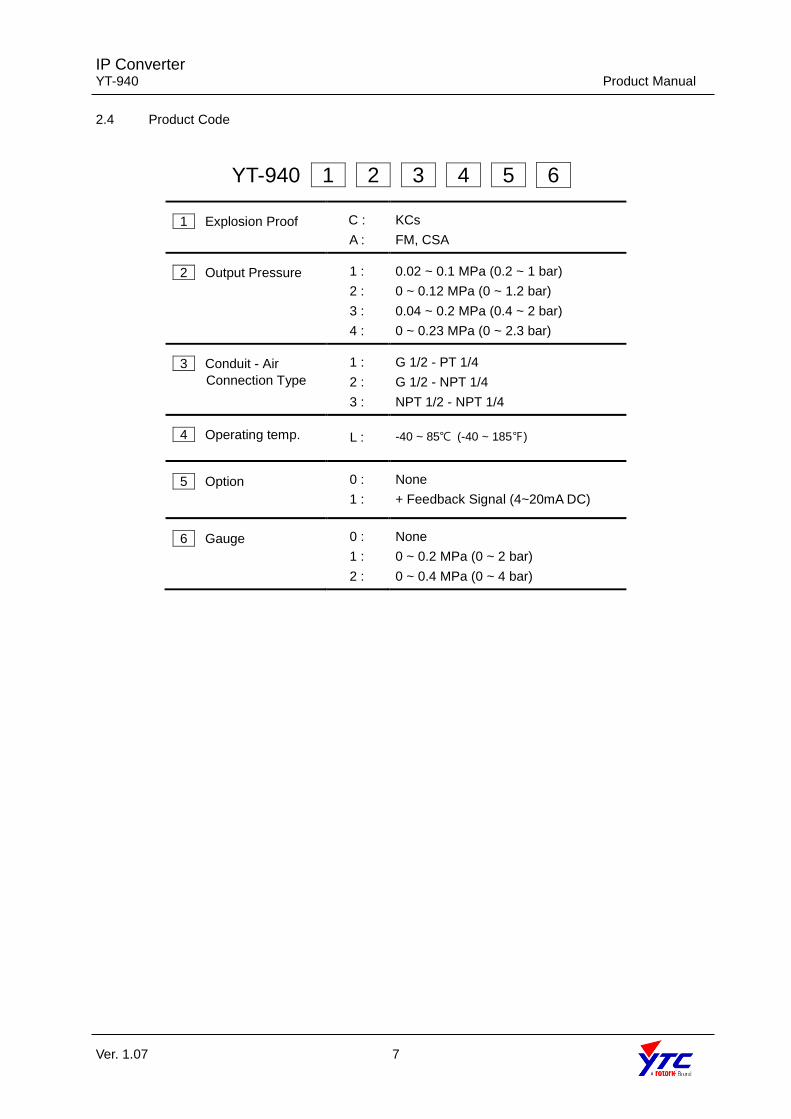
2.4 Product Code
YT-940 1 2 3 4 5 6
1 Explosion Proof C :
A :
KCs
FM, CSA
2 Output Pressure 1 :
2 :
3 :
4 :
0.02 ~ 0.1 MPa (0.2 ~ 1 bar)
0 ~ 0.12 MPa (0 ~ 1.2 bar)
0.04 ~ 0.2 MPa (0.4 ~ 2 bar)
0 ~ 0.23 MPa (0 ~ 2.3 bar)
3 Conduit - Air
Connection Type
1 :
2 :
3 :
G 1/2 - PT 1/4
G 1/2 - NPT 1/4
NPT 1/2 - NPT 1/4
4 Operating temp. L : -40 ~ 85℃ (-40 ~ 185℉)
5 Option 0 :
1 :
None
+ Feedback Signal (4~20mA DC)
6 Gauge 0 :
1 :
2 :
None
0 ~ 0.2 MPa (0 ~ 2 bar)
0 ~ 0.4 MPa (0 ~ 4 bar)

IP Converter YT-940 Product Manual
Ver. 1.07 8
2.5 Product Specification
Model YT-940
Input Signal 4~20mA DC
Impedance Max. 313Ω @ 20mA DC
Output Signal
Standard 0.02 ~ 0.1 MPa (0.2 ~ 1.0 bar)
Multi-range
0.00 ~ 0.12 MPa (0 ~ 1.2 bar)
0.04 ~ 0.2 MPa (0.4 ~ 2.0 bar)
0.00 ~ 0.23 MPa (0 ~ 2.3 bar)
Supply Pressure
Standard 0.13 ~ 0.16 MPa (1.2 ~ 1.6 bar)
Minimum 0.02 MPa higher than Max Output pressure
Maximum 0.24 MPa (2.4 bar)
Explosion Proof Flameproof enclosure. Refer to “2.6 Certifications”
Ambient Temperature
Operating -40 ~ 85℃ (-40 ~ 167℉)
Explosion Proof T5 -40 ~ 85℃ (-40 ~ 185℉)
T6 -40 ~ 75℃ (-40 ~ 167℉ㅇ)
Air Consumption Below 2 LPM (Sup. = 0.14 MPa @ idle)
Flow Capacity 70 LPM (Sup. = 0.14 MPa)
Linearity ±0.5% F.S.
Hysteresis ±0.5% F.S.
Sensitivity ±0.2% F.S
Repeatability ±0.3% F.S.
Air Connection PT 1/4 or NPT 1/4
Conduit Entry G(PF) 1/2 or NPT 1/2
Ingress Protection Type 4X, IP66
Housing Material Aluminum Diecasting
Weight 3.0kg (6.61 lb)
Painting Polyester Powder Coating
Internal Free Volume 700 cm3
Tested under ambient temperature of 20’C, absolute pressure of 760mmHg, and humidity of 65%. Please contact
Young Tech Co., Ltd for detailed testing specification.
IP Converter YT-940 Product Manual
Ver. 1.07 9
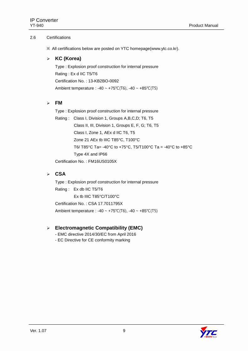
2.6 Certifications
※ All certifications below are posted on YTC homepage(www.ytc.co.kr).
➢ KC (Korea)
Type : Explosion proof construction for internal pressure
Rating : Ex d IIC T5/T6
Certification No. : 13-KB2BO-0092
Ambient temperature : -40 ~ +75℃(T6), -40 ~ +85℃(T5)
➢ FM
Type : Explosion proof construction for internal pressure
Rating : Class I, Division 1, Groups A,B,C,D; T6, T5
Class II, III, Division 1, Groups E, F, G; T6, T5
Class I, Zone 1, AEx d IIC T6, T5
Zone 21 AEx tb IIIC T85°C, T100°C
T6/ T85°C Ta= -40°C to +75°C, T5/T100°C Ta = -40°C to +85°C
Type 4X and IP66
Certification No. : FM16US0105X
➢ CSA
Type : Explosion proof construction for internal pressure
Rating : Ex db IIC T5/T6
Ex tb IIIC T85°C/T100°C
Certification No. : CSA 17.7011795X
Ambient temperature : -40 ~ +75℃(T6), -40 ~ +85℃(T5)
➢ Electromagnetic Compatibility (EMC)
- EMC directive 2014/30/EC from April 2016
- EC Directive for CE conformity marking
IP Converter YT-940 Product Manual
Ver. 1.07 10
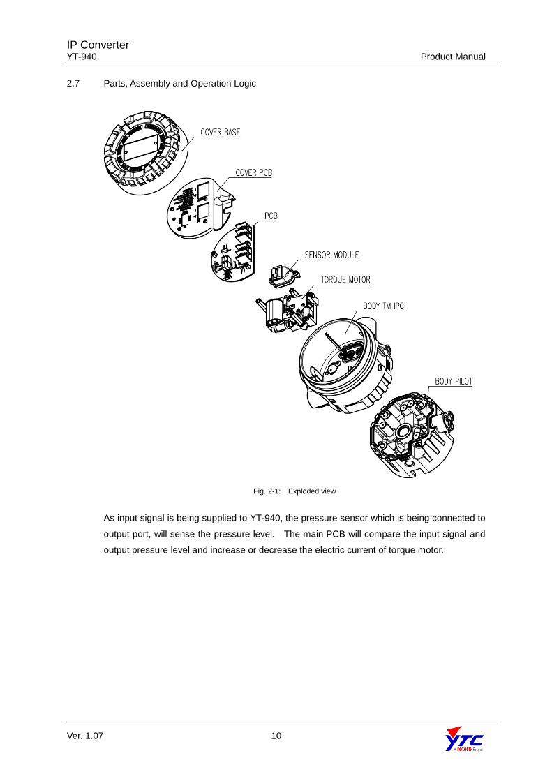
2.7 Parts, Assembly and Operation Logic
Fig. 2-1: Exploded view
As input signal is being supplied to YT-940, the pressure sensor which is being connected to
output port, will sense the pressure level. The main PCB will compare the input signal and
output pressure level and increase or decrease the electric current of torque motor.
IP Converter YT-940 Product Manual
Ver. 1.07 11
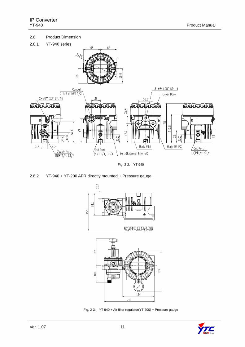
2.8 Product Dimension
2.8.1 YT-940 series
Fig. 2-2: YT-940
2.8.2 YT-940 + YT-200 AFR directly mounted + Pressure gauge
Fig. 2-3: YT-940 + Air filter regulator(YT-200) + Pressure gauge

IP Converter YT-940 Product Manual
Ver. 1.07 12
3. Installation
3.1 Safety and Installation Tips
When installing the unit, please ensure to read and follow safety instructions.
➢ Any input or supply pressures to valve, actuator, and / or to other related devices must
be turned off.
➢ Use bypass valve or other supportive equipment to avoid entire system “shut down”.
➢ In case of hazardous area, please ensure there is no explosion gas in the atmosphere.
➢ When installing the unit, please ensure the cover base is headed upward, so internal
dew condensation can go out through the draining hole.
※ Installed in accordance with the National Electrical Code(NEC), ANSI/NFPA 70, or
CEC Part 1 as applicable.(FM approved product)
4. Connection - Air
4.1 Safety
➢ Supply pressure should be clean and dry air – avoiding moisture, oil and dust.
➢ Always recommended to use air filter regulator (i.e. YT-200 series).
➢ Young Tech Co., Ltd has not tested positioner’s operation with any other gases
other than clean air. Please contact Young Tech Co., Ltd for any questions.
4.2 Supply Pressure Condition
➢ Dry air with dew point of at least 10℃ lower than ambient temperature.
➢ Avoid from dusty air. If require, we recommend to use air filter regulator which contains
5 micron or lower filter (YT-200)
➢ Avoid oil.
➢ Comply with ISO 8573-1 or ISA 7.0.01.
➢ Is designed to be used with the pressure below 0.24 MPa (2.4 bar).
➢ Set air filter regulator’s pressure level 0.02 MPa (0.2 bar) higher than required max
output pressure.
4.3 Piping Condition
➢ Ensure inside of pipe is clean of obstructions.
➢ Do not use pipeline that is squeezed or shows any type of damamges.
➢ Pipeline should have more than 6mm of inner diameter (10mm outer diameter) to
maintain flow rate.
➢ The length of pipeline system should not be extremely long. Longer pipeline system
may affect flow rate due to the friction inside of the pipeline.
IP Converter YT-940 Product Manual
Ver. 1.07 13
5. Connection – Power
5.1 Safety
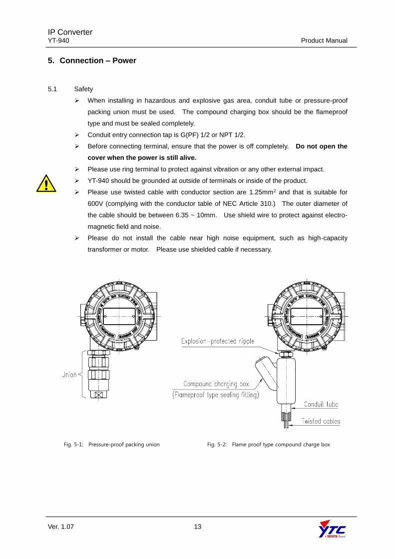
➢ When installing in hazardous and explosive gas area, conduit tube or pressure-proof
packing union must be used. The compound charging box should be the flameproof
type and must be sealed completely.
➢ Conduit entry connection tap is G(PF) 1/2 or NPT 1/2.
➢ Before connecting terminal, ensure that the power is off completely. Do not open the
cover when the power is still alive.
➢ Please use ring terminal to protect against vibration or any other external impact.
➢ YT-940 should be grounded at outside of terminals or inside of the product.
➢ Please use twisted cable with conductor section are 1.25mm2 and that is suitable for
600V (complying with the conductor table of NEC Article 310.) The outer diameter of
the cable should be between 6.35 ~ 10mm. Use shield wire to protect against electro-
magnetic field and noise.
➢ Please do not install the cable near high noise equipment, such as high-capacity
transformer or motor. Please use shielded cable if necessary.
Fig. 5-1: Pressure-proof packing union Fig. 5-2: Flame proof type compound charge box

IP Converter YT-940 Product Manual
Ver. 1.07 14
5.2 Terminal Overview
Fig. 5-3: Terminal Overview
5.2.1 Input Signal Terminal
1. Open cover base.
2. Please use appropriate union by considering the operating condition. Insert cable with
using proper flameproof type packing union
3. Locate cable entry {G(PF) 1/2 or NPT 1/2} of input signal on the left hand and bottom
side of the product. Insert cables into the conduit entry and secure them with (+) and (-)
terminals on the plate. Make sure to tighten bolts with 1.5 N·m (15 Kgf·cm) torque.
Please check the polarity of the terminals.
4. There are two terminals for grounding.
5. Ground resistance must be below 100 ohm.
AO: Analog Output
AI: Analog Input
Vs: Voltage Source
RL: Load
Resistance

IP Converter YT-940 Product Manual
Ver. 1.07 15
6. Adjustments
Before our product is dispatched from our factory, input signal against supply pressure or supply
pressure against input signal will be set correctly. But, if additional setting requires, please see
below.
6.1 Zero and Span Adjustments of Input Signal
(Based on 4~20mA / 0.02~0.1 MPa)
1. After wirings have been completed, please supply 4mA as input signal to YT-940. Please
check output pressure and adjust zero adjustment bolt by using small (-) screw driver. In
general, zero should be set at 0.02 MPa
2. Supply 20mA. Please check output pressure and adjust span adjustment bolt to required
end output. In general, span should be set at 0.1 MPa.
3. Supply 4mA again. Please check the output pressure and repeat step 1 and 2 until
required point have been set completely.
4. Close the cover base completely
6.2 Zero and Span Adjustments of Feedback Signal
(Based on 4~20mA / 0.02~0.1 MPa)
1. Feedback signal requires DC 9~28V. Supply 4mA. Please check if the output pressure is
at zero point and receive feedback signal correctly. If not, adjust zero adjustment bolt by
using small (-) screw driver until the receiving feedback signal is set as 4mA.
2. Supply 20mA. Please check if the output pressure is at end point and receive feedback
signal correctly. If not, adjust span adjustment bolt by using small (-) screw driver until
the receiving feedback signal is set as 20mA
3. Supply 4mA again. Please check the feedback signal and repeat step 1 and 2 until
required point have been set completely.
6. Close the cover base completely before using the product.
Fig. 6-1: Zero, Span

IP Converter YT-940 Product Manual
Ver. 1.07 16
Fig. 6-2: DA, RA setting
6.3 DA and RA setting relative to the input signal
The above figure shows a PCB with plastic PCB cover removed. If the “Output Pressure”
switch is switched to DA direction, the output pressure increases when the current
increases. If it is switched to RA direction, the output pressure decreases when the
current increases.
6.4 DA and RA setting relative to feedback signal (Only feedback signal option)
If the “Feedback Signal” switch is switched to DA direction, the feedback signal current
increases when the output pressure increases. If it’s switched to RA direction, the
feedback signal current decrease when the output pressure increase.
IP Converter YT-940 Product Manual
Ver. 1.07 17
Manufacturer:
Young Tech Co., Ltd
81, Hwanggeum-ro, 89 Beon-gil, Yangchon-eup
Gimpo-si, Gyeonggi-do, South Korea 10048
Tel: +82-31-986-8545
Fax: +82-70-4170-4927
Email: [email protected]
Homepage : http://www.ytc.co.kr
Issued : 2018-09-10
Copyright © Young Tech Co., Ltd. All Rights Reserved.