ip-241 krd-482-e slack adjuster install & maint · installation and maintenance guide slack...
TRANSCRIPT
R a i l V e h i c l e S y s t e m s
IP-241 Rev 07 3/9/2016 - en
Installation and Maintenance Guide
Slack Adjuster Model KRD-482-E and KRD-482-R P/N 783901, 790196

Installation & Maintenance Guide S/A KRD-482-E, KRD-482-R Doc.-No.: IP-241 Revision: 07 3/9/16 – en
Copyright 2016© New York Air Brake AG. All rights reserved, including industrial property rights applications. New York Air Brake AG retains any power of disposal, such as copying and transferring.
Page 2 / 18
Contact Address
New York Air Brake
748 Starbuck Avenue
Watertown, NY 13601
USA
Phone: +1 315 786 5200
Fax: +1 315 786 5676
www.nyab.com
Confidentiality
The information in this document and the document itself, in whole or in part, in any form ("Information") is proprietary and/or confidential property of New York Air Brake, a Knorr Brake company, and its affiliates and its successors and as-signees, who retain and reserve all right, title and interest in this Information in whole or in part and in all forms. This Information is provided to the original recipient only for confidential use, with the understanding that it will not be used in any manner detri-mental to the interests of New York Air Brake, and subject to return on request. Reproduction, transmission, distribution or publication of this Information in any form, in whole or in part, for any purpose without prior written permission of New York Air Brake is strictly prohibited. © Copyright New York Air Brake All rights reserved. CONFIDENTIAL

Installation & Maintenance Guide S/A KRD-482-E, KRD-482-R Doc.-No.: IP-241 Revision: 07 3/9/16 – en
Copyright 2016© New York Air Brake AG. All rights reserved, including industrial property rights applications. New York Air Brake AG retains any power of disposal, such as copying and transferring.
Page 3 / 18
Revision History
Rev Date Name Para Description of change
01 2/27/08 T. Baty Original Issue
02 10/1/08 D. Call Sec. 2.2 & 3.0
Pg. 6
Pg. 7
Dwg. reference IP-241 was IP-178.
Dimension 80” to 83” was 81” to 84”.
Dimension 81” to 83” was 81” to 84”.
03 7/9/10 D. Call Pages 6 & 7 Added detail information.
04 2/11/14 V. Moore Title & Sec. 2
All
Added P/N 790196 and Note for proper orientation of drain holes.
Reformatted document in COPE.
05 12/3/15 V. Moore Title & Sec. 1.1 Added reference to Group “R”.
06 1/21/16 V. Moore Pg. 6
Pg. 9
Pg. 10
Pg. 11
Pg. 12
Pg. 14
Para. 1.4: removed ‘KRD-482-E’.
Para. 3.1.2: removed handbrake in-struction.
Removed para. 3.1.3 and 3.1.5.
Removed para. 3.1.16.
Para. 4: clarified third Notice w/picture.
Para. 4.3: inserted view of drawing.
Para. 4.10: removed 7-8” and 5-6” pis-ton stroke length.
Para. 6: removed ‘and return to NYAB for replacement’.
Sec. 7: removed 7.1, 7.2, 7.3 and added reference to AAR standards.
07 3/9/16 V. Moore Sec. 7 Replaced 7.1, 7.2 and 7.3 with: ‘Test per the requirements of Chart “A” in Rule 3 of the AAR field manual’.
The original document was issued in English language.
Installation & Maintenance Guide S/A KRD-482-E, KRD-482-R Doc.-No.: IP-241 Revision: 07 3/9/16 – en
Copyright 2016© New York Air Brake AG. All rights reserved, including industrial property rights applications. New York Air Brake AG retains any power of disposal, such as copying and transferring.
Page 4 / 18
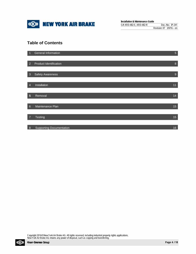
Table of Contents
1 General Information 5
2 Product Identification 8
3 Safety Awareness 9
4 Installation 11
5 Removal 14
6 Maintenance Plan 15
7 Testing 15
8 Supporting Documentation 16
Installation & Maintenance Guide S/A KRD-482-E, KRD-482-R Doc.-No.: IP-241 Revision: 07 3/9/16 – en
Copyright 2016© New York Air Brake AG. All rights reserved, including industrial property rights applications. New York Air Brake AG retains any power of disposal, such as copying and transferring.
Page 5 / 18
1 General Information
CAUTION
Please read this document from start to finish to ensure safety of operation and to avoid personal injuries and damage to equipment.
1.1 Introduction
This manual contains particulars specific to Slack Adjuster Model KRD-482-E and Model KRD-482-R. This document defines the steps for proper installation of the Slack Adjusters P/N 783901 and 790196.
1.2 Technical Changes
New York Air Brake reserves the right to change the equipment or this document at any time without giv-ing special notice.
1.3 Target group for this document This document is intended for use by trained service technicians who:
• Have the skill, experience, safety awareness and professional ability to install or replace air brake products
• Have read and understand this document in its entirety
• Are familiar with the safety codes and accident prevention regulations for these activities
NOTE
This document will be useful to other target groups as well, e.g. project engineers.
However, it does not claim to provide complete information for such target groups.

Installation & Maintenance Guide S/A KRD-482-E, KRD-482-R Doc.-No.: IP-241 Revision: 07 3/9/16 – en
Copyright 2016© New York Air Brake AG. All rights reserved, including industrial property rights applications. New York Air Brake AG retains any power of disposal, such as copying and transferring.
Page 6 / 18
1.4 Referenced Documents
Doc. ID
Doc. No Issue (In-dex, ..)
Title
/1/ S-400 AAR Standard
/2/ S-420 AAR Standard
/3/ S-421 AAR Standard
/4/ S-422 AAR Standard
/5/ 784600 Installation Drawing, Slack Adjuster
1.5 Danger, Warning, Caution, and Notice Messages
These symbols indicate that important personal safety information follows. Carefully read and understand each safety related text message and apply the message to the operation and maintenance of the system as defined in the safety alert message. The following are definitions associated with the different safety alert message categories. The words DANGER, WARNING, and CAUTION are used to identify levels of hazard seriousness for the safety of the personnel and the equipment. The word DANGER is used to signify an immediate hazard and is used throughout this manual in the fol-lowing manner:
DANGER
Indicates an imminently hazardous situation, which if not avoided, will result in death or serious injury. This word is to be limited to the most extreme situations.
The word WARNING is used to signify hazards or unsafe practices and is used throughout this manual in the following manner:
WARNING Failure to comply with these instructions may lead to irreversible physical injuries which may have fatal consequences.
The word CAUTION just like the word WARNING is used to signify hazards or unsafe practice in addition to equipment damage and is used throughout this manual in the following manner:
Installation & Maintenance Guide S/A KRD-482-E, KRD-482-R Doc.-No.: IP-241 Revision: 07 3/9/16 – en
Copyright 2016© New York Air Brake AG. All rights reserved, including industrial property rights applications. New York Air Brake AG retains any power of disposal, such as copying and transferring.
Page 7 / 18
CAUTION Failure to comply with these instructions may lead to personal inju-ries and/or to damage to the unit or the environment.
The NOTE (NOTICE) messages are used throughout this manual in the following manner:
NOTE Notes do not contain any messages relevant to safety.
Notes contain useful hints and additional information used to high-light suggestions which will result in enhanced installation, reliabil-ity, or operation.
Safety messages/notes have a specific structure which is explained here for DANGER (This also applies to WARNINGS and CAUTIONS):
DANGER
Source of the danger
Consequences of the danger
Remedial measures
Notes do not contain any messages relevant to safety and are included only for the sake of complete-ness.
NOTE
Notes contain useful hints and additional information about the unit.

Installation & Maintenance Guide S/A KRD-482-E, KRD-482-R Doc.-No.: IP-241 Revision: 07 3/9/16 – en
Copyright 2016© New York Air Brake AG. All rights reserved, including industrial property rights applications. New York Air Brake AG retains any power of disposal, such as copying and transferring.
Page 8 / 18
2 Product Identification
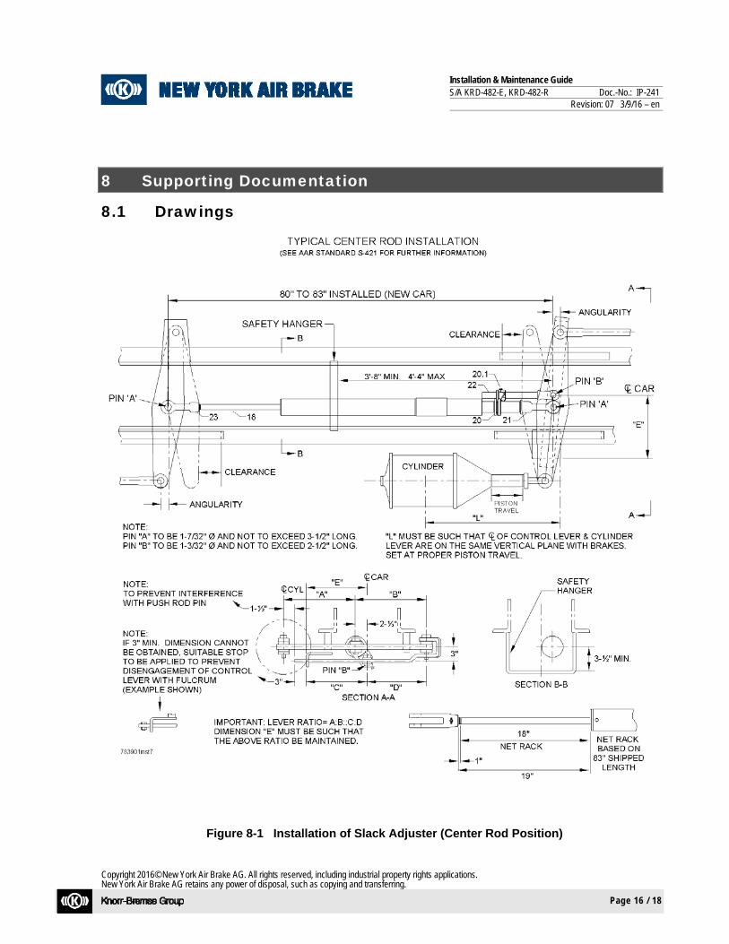
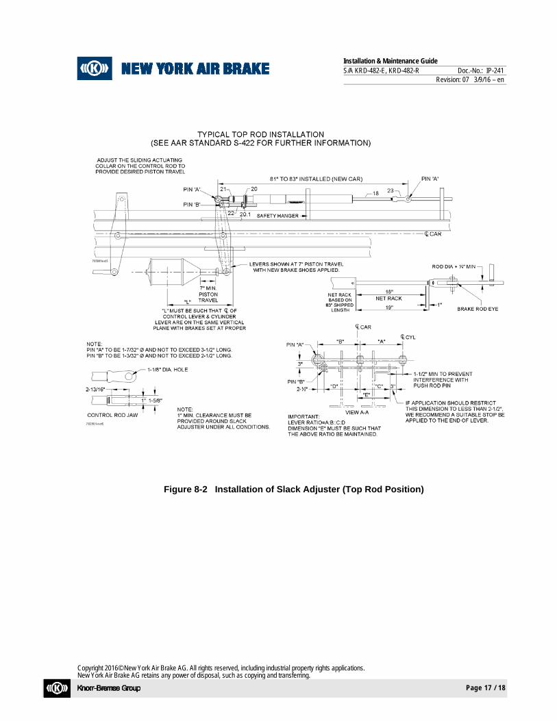
2.1 General Description Slack adjusters are most commonly located in the center rod (Fig. 8-1) or top rod position (Fig. 8-2) of conventional foundation brake rigging. In any case, they must be installed with reference to the applica-ble installation drawing (NYAB P/N 784600) and the appropriate AAR standards for Group E Slack Ad-justers. (S-400, S-420, S-421, S-422)
2.2 Installation Drawings
Refer to Figures 8-1 and 8-2 at the end of this document.
Installation & Maintenance Guide S/A KRD-482-E, KRD-482-R Doc.-No.: IP-241 Revision: 07 3/9/16 – en
Copyright 2016© New York Air Brake AG. All rights reserved, including industrial property rights applications. New York Air Brake AG retains any power of disposal, such as copying and transferring.
Page 9 / 18
3 Safety Awareness
3.1 General Safety Awareness
3.1.1 Observe all rules and regulations of the railroad where the equipment is being used. When-ever there is a conflict between the instructions given in this manual and the instructions of the user railroad, the rules and regulations of the user railroad will govern.
3.1.2 When performing any test work on devices or equipment while they are on the vehicle (on vehicle test, etc.) special precautions must be taken to ensure that vehicle movement will not occur which could result in injury to personnel and/or damage to equipment. Make sure the wheels are chocked to prevent vehicle from moving. Verify that the vehicle and/or track where work is being conducted, is properly flagged to prevent injury from movement of other vehicles.
3.1.3 De-pressurize air system before loosening connections or components. Before removing any component from its mountings, the train must be safely parked. To prevent personal injury, all main reservoir, brake supply reservoir, and brake cylinder air pressure on the affected ve-hicle must be vented.
3.1.4 The use of an air jet, which must be less than 2.11 (30 PSI), to blow parts clean or to blow
them dry after being cleaned with a solvent will cause particles of dirt and/or droplets of the cleaning solvent to be airborne. These particles and droplets may cause skin and /or eye irrita-tion. Personal eye protection must be worn to protect the eyes from possible injury. When us-ing an air jet do not direct it toward another person.
3.1.5 If degreasing fluids are used for cleaning purposes, the current local safety regulations plus the safety precautionary statements of the manufacturer of the cleaning agent must be adhered to. Otherwise, physical harm could result from the inhalation of toxic fumes. Make sure the area is well ventilated when working with materials that produce harmful fumes.
3.1.6 Personal eye protection must be worn when doing any work to protect eyes from possible inju-
ry. 3.1.7 When performing maintenance procedures on system components, assemblies may be under
a spring load. Exercise caution during disassembly so that no parts “Fly Out” and cause bodily injury.
3.1.8 Where fasteners removed from the equipment are not satisfactory for reuse, care must be
taken to select replacements that match the originals. Mismatched or incorrect fasteners can result in equipment damage or malfunction, or possible personal injury.
3.1.9 Follow all WARNINGS, CAUTIONS and NOTES found throughout this Manual. If you must
use a work procedure or tool which is not recommended, you must first satisfy yourself that neither your safety, nor your fellow workers safety, nor that of the equipment, will be jeopard-ized by the method selected.
3.1.10 To ensure the correct functioning of each component, use only the manufacturers genuine
spare parts as replacements.
Installation & Maintenance Guide S/A KRD-482-E, KRD-482-R Doc.-No.: IP-241 Revision: 07 3/9/16 – en
Copyright 2016© New York Air Brake AG. All rights reserved, including industrial property rights applications. New York Air Brake AG retains any power of disposal, such as copying and transferring.
Page 10 / 18
3.1.11 Appropriate tool selection is required when performing all maintenance operations to avoid per-sonal injury.
3.1.12 Person(s) having the appropriate job skill level, as governed by the user railroad, are required when performing maintenance and/or operational tasks with the brake system and system com-ponents.
3.1.13 Whenever a valve or system component is removed from a vehicle for any reason, and it is reinstalled or replaced with a new or repaired and tested component, a stationary vehicle air brake test and an equipment test must be performed to ensure that the component functions properly within the system.

Installation & Maintenance Guide S/A KRD-482-E, KRD-482-R Doc.-No.: IP-241 Revision: 07 3/9/16 – en
Copyright 2016© New York Air Brake AG. All rights reserved, including industrial property rights applications. New York Air Brake AG retains any power of disposal, such as copying and transferring.
Page 11 / 18
4 Installation
NOTE
Slack adjusters are most commonly located in the center rod (Figure 8-1) or top rod position (Figure 8-2) of conventional foundation brake rigging. In any case, they must be installed with reference to the applicable installation drawing (NYAB P/N 784600) and the appro-priate AAR standards for Group E Slack Adjusters. (S-400, S-420, S-421, S-422)
(See Figures 8-1 and 8-2)
NOTE
NYAB recommends installing NEW brake shoes when a Slack Ad-juster is installed.
NOTE
For installation of P/N 790196, drain holes in housing must be facing down (see Figure 4-1).
Figure 4-1 Slack Adjuster KRD-482-R

Installation & Maintenance Guide S/A KRD-482-E, KRD-482-R Doc.-No.: IP-241 Revision: 07 3/9/16 – en
Copyright 2016© New York Air Brake AG. All rights reserved, including industrial property rights applications. New York Air Brake AG retains any power of disposal, such as copying and transferring.
Page 12 / 18
4.1 Attach Front Clevis (21) to Cylinder Lever of brake rigging using an AAR Type “A” Pin - 1-7/32"
dia. X 3-1/2" long.
4.2 Adjust length of Slack Adjuster as required by turning Adjuster Spindle (18) using the Spindle Clevis (23), so that the hole in Spindle Clevis (23) lines up with the hole in the fulcrum lever of the brake rigging.
4.3 Once a proper length is acquired, attach Rear Clevis (23) to Fulcrum Lever of brake rigging using
an AAR Type “A” Pin 1-7/32" dia. X 3-1/2" long pin.
Figure 4-2 Slack Adjuster Installation (Center Rod Position)
NOTE
Control lever must conform to the requirements of AAR Standard S-420, S-421, and S-422.

Installation & Maintenance Guide S/A KRD-482-E, KRD-482-R Doc.-No.: IP-241 Revision: 07 3/9/16 – en
Copyright 2016© New York Air Brake AG. All rights reserved, including industrial property rights applications. New York Air Brake AG retains any power of disposal, such as copying and transferring.
Page 13 / 18
4.4 Install clevis of Control Rod (22) onto Control Lever of the brake rigging using an AAR Type “B” Pin - 1-3/32" dia. X 2-1/2" long.
4.5 Adjust sliding Actuating Collar (20) on Control Rod (22), securing with Locking Bolt (20.1).
4.6 Using 50 psi brake cylinder pressure, check piston stroke. A minimum of (2) applications is re-
quired to verify piston stroke. (See steps 4.10 through 4.13) 4.7 Install safety hanger, per AAR Standard S-400, approximately 44"-52" from center pin on Cylinder
Lever of the brake rigging.
4.8 Maintain 1" clearance around Slack Adjuster under ALL conditions per AAR standard S-400. 4.9 If this is a first car in a series, measure the length of the Control Rod to allow “pre-setting” of the
Control Shaft on subsequent cars. Piston stroke must be measured on ALL cars prior to welding of Actuating Collar (20) to Control Rod (22).
Setting proper piston stroke (See Figures 8-1 and 8-2):
4.10 Proper piston stroke for an 8-1/2" or 10" cylinder must be set per Section 3 of the AAR Field
Manual.
4.11 Apply and release the brakes using 50 psi brake cylinder pressure, then apply the brakes again. While brakes are applied, measure the piston stroke on the brake cylinder. Release the brakes.
4.12 Adjust the piston stroke by adjusting the length of the Control Rod (22) via the Actuating Collar
(20). Shorten the Control Rod to increase piston stroke, and lengthen the Control Rod to de-crease piston stroke. The adjustment necessary is a multiple of the car’s lever ratio.
EXAMPLE: A car with a 2:1 Lever Ratio will need a ½" adjustment on the Control Rod to
create a 1" difference on the piston stroke.
4.13 Once proper piston stroke is achieved, weld Actuating Collar (20) to Control Rod (22) with 3/16" Fillet welds, minimum (2) sides for a minimum total weld length of 2".

Installation & Maintenance Guide S/A KRD-482-E, KRD-482-R Doc.-No.: IP-241 Revision: 07 3/9/16 – en
Copyright 2016© New York Air Brake AG. All rights reserved, including industrial property rights applications. New York Air Brake AG retains any power of disposal, such as copying and transferring.
Page 14 / 18
5 Removal
NOTE
Release the brakes and insure that all tension is out of the brake rigging before attempting to remove a Slack Adjuster. Follow all safety guidelines for working on or around railroad equipment.
5.1 Remove the pin attaching the Control Rod (22) to the Control Lever on the brake rigging. 5.2 Remove pin connecting the Rear Clevis (23) from the Fulcrum Lever on the brake rigging. 5.3 Support the loose end of the Slack Adjuster, and remove the pin connecting the Front Clevis
(21) to the Cylinder Lever on the brake rigging. 5.4 Remove the Slack Adjuster unit from the car.

Installation & Maintenance Guide S/A KRD-482-E, KRD-482-R Doc.-No.: IP-241 Revision: 07 3/9/16 – en
Copyright 2016© New York Air Brake AG. All rights reserved, including industrial property rights applications. New York Air Brake AG retains any power of disposal, such as copying and transferring.
Page 15 / 18
6 Maintenance Plan
NYAB Slack Adjusters do not require any special maintenance or servicing. Maintenance consists of checking for proper piston stroke per section 4, and visual inspections for damage or malfunc-tions during normal car servicing. If any of the visual inspection conditions are found, remove the unit from the car and return to New York Air Brake for replacement.
7 Testing
WARNING
Secure, and properly flag, any car where personnel will be under and/or near. Follow all safety procedures for working on or around railroad equipment. Failure to follow these procedures could result in injury or death.
7.1 Test per the requirements of chart “A” in Rule 3 of the AAR field manual.
Installation & Maintenance Guide S/A KRD-482-E, KRD-482-R Doc.-No.: IP-241 Revision: 07 3/9/16 – en
Copyright 2016© New York Air Brake AG. All rights reserved, including industrial property rights applications. New York Air Brake AG retains any power of disposal, such as copying and transferring.
Page 16 / 18
8 Supporting Documentation
8.1 Drawings
Figure 8-1 Installation of Slack Adjuster (Center Rod Position)
Installation & Maintenance Guide S/A KRD-482-E, KRD-482-R Doc.-No.: IP-241 Revision: 07 3/9/16 – en
Copyright 2016© New York Air Brake AG. All rights reserved, including industrial property rights applications. New York Air Brake AG retains any power of disposal, such as copying and transferring.
Page 17 / 18
Figure 8-2 Installation of Slack Adjuster (Top Rod Position)

Installation & Maintenance Guide S/A KRD-482-E, KRD-482-R Doc.-No.: IP-241 Revision: 07 3/9/16 – en
Copyright 2016© New York Air Brake AG. All rights reserved, including industrial property rights applications. New York Air Brake AG retains any power of disposal, such as copying and transferring.
Page 18 / 18
8.2 List of Abbreviations
Abbreviation or Acronym Definition
AAR Association of American Railroads
Dia. Diameter
Doc. Document
Dwg. Drawing
e.g. For example
En English
Fig. Figure
ID Identification
IP Instructional Pamphlet
Max. Maximum
Min. Minimum
No. Number
NYAB New York Air Brake
Para. Paragraph
Pg. Page
P/N Part number
Psi Pounds per square inch (pressure)
Rev. Revision