iowa state university electrical and computer engineering...
TRANSCRIPT

E E 452. Electric Machines and Power Electronic Drives Iowa State University
Revision 7/16/2012. Nicholas David
0-1
Iowa State University
Electrical and Computer Engineering
E E 452. Electric Machines and Power Electronic Drives
Laboratory Environment Setup:
Software Installation, Setup, and Programming
Summary
ControlSUITE, Code Composer Studio (CCS), and MATLAB/Simulink – Embedded Coder are
used to implement embedded control systems on the F28035 microcontroller. This
document describes how to install, setup, and use these applications.
Important: Turn off “Windows User Account Control” for all installations.
Note: Embedded Coder v6.1 is intended for use with Code Composer Studio v4. However,
Texas Instruments no longer supports CCSv4 and encourages users to migrate to CCSv5.
To deal with this conflict, MATLAB/Simulink – Embedded Coder will be configured as if it
were working with CCSv4. The build process and resulting executable file are the same for
both versions. Automatic downloading of the executable file to the MCU is supported for
CCSv4, but is not supported for CCSv5. The executable file must be downloaded to the
target device from within CCSv5.

E E 452. Electric Machines and Power Electronic Drives Iowa State University
Revision 7/16/2012. Nicholas David
0-2
1. ControlSUITE
ControlSUITE is a comprehensive set of tools to support TI C2000 devices.
ControlSUITE consists of a library of folders, stored on the local computer drive, and
contains items such as hardware guides, software libraries, applications notes, and
example projects. ControlSUITE also has a GUI which simplifies navigation and viewing
of content.
a. Install ControlSUITE
Prerequisites: None
ControlSUITE can be obtained directly from Texas Instruments at the following
location:
http://www.ti.com/tool/controlsuite.
Install ControlSUITE via the .zip folder to avoid missing files in the download.
Extracting the .zip folder creates a folder called “sprca85”. This folder has many
*.cab files, and one “controlsuite.msi” installer file; run this file as an administrator.
Install ControlSUITE to C:\TI. If asked to select components to install, install
support for all devices and kits.
For more details, refer to SPRUGU2B, ControlSUITE Getting Started Guide, available
at http://www.ti.com/lit/ml/sprugu2b/sprugu2b.pdf.
Restart the computer after installation.
b. Verify ControlSUITE Installation
Open the ControlSUITE GUI via the Windows Start menu, desktop, or installation
directory. The ControlSUITE GUI is powered by Crosshairs Embedded. If a
Crosshairs icon appears in the Windows task bar, on the bottom right of the screen,
but the ControlSUITE GUI does not open, open the Windows Firewall and allow full
access for “crosshairs[engine].exe”.

E E 452. Electric Machines and Power Electronic Drives Iowa State University
Revision 7/16/2012. Nicholas David
0-3
2. Code Composer Studio
Code Composer Studio (CCS) is an integrated development environment (IDE) used to
program TI C2000 microcontrollers. Programs can be written using the libraries of
premade software sets available in ControlSUITE.
a. Install Code Composer Studio v5
Prerequisites: Microsoft .NET Framework 3.5
ActivePerl
http://www.activestate.com/activeperl/downloads
F2803x C/C++ Header Files and Peripherals
http://www.ti.com/tool/sprc892, install to C:\tidcs
Ensure your computer meets the system requirements listed here:
http://processors.wiki.ti.com/index.php/System_Requirements.
Code Composer Studio can be obtained directly from TI at the following location:
http://processors.wiki.ti.com/index.php/Download_CCS.
Install Code Composer Studio v5 to C:\ticcsv5. For installation details, refer to the
CCSv5 Getting Started Guide, available at:
http://processors.wiki.ti.com/index.php/CCSv5_Getting_Started_Guide.
Restart the computer after installation.
b. Verify CCS v5 Installation
For licensing instructions, follow CCSv5 Running for the first time, available at
http://processors.wiki.ti.com/index.php/GSG:CCSv5_Running_for_the_first_time.
When CCS is opened, a prompt will appear to specify a “workspace”. The workspace
is a location which contains all project dependent files while working in the CCS IDE.
This workspace should be located at C:\CCSworkspace, and will need to be
read/write enabled for all users. The workspace can be considered a temporary
location, in which a project is imported to for development. When done working
with a project in CCS, the edited project should be relocated to the student’s external
location for storage; this can be a network location or other storage media.
DO NOT check the box which asks to use this as the default location; other users
should be able to specify a different workspace if desired.

E E 452. Electric Machines and Power Electronic Drives Iowa State University
Revision 7/16/2012. Nicholas David
0-4
When a new workspace is made, a default folder called “.metadata” is generated in
the location specified. Do not delete this folder; it contains information regarding
the CCS configuration. If you encounter problems with the build process, or cannot
launch a debug session, delete the current workspace, including the .metadata file,
and import the project to a new one; this will restore default CCS configurations.
Note: The workspace should be located on the local machine, on the same drive
which has CCS installed.
Code Composer Studio must run properly before configuring Embedded Coder. To
verify operation of Code Composer Studio, load a test program to blink an LED. This
is described in SPRUFR5E, Experimenter’s Quick Start Guide, available at
http://www.ti.com/lit/ml/sprufr5f/sprufr5f.pdf.
Further details can be found in System Framework Overview, located in
ControlSUITE under the section “ControlCARD: Experimenter’s Kit”.

E E 452. Electric Machines and Power Electronic Drives Iowa State University
Revision 7/16/2012. Nicholas David
0-5
3. Building a Program with Code Composer Studio
CCS offers the option of writing and debugging code in both Assembly and C. Programs
are generated for a device by building a project. The project contains all of the files
necessary to create the machine code, which is downloaded to the device. Example
programs are made available to provide quick learning of the CCS IDE. These programs
are available in the ControlSUITE package. Use the Flashing LEDs F28035 project to
verify operation of CCS. Open CCS and select File/Import. Navigate to
ControlSUITE\development_kits\TemplateProjects and select the example project for
your kit.
a. Settings to Verify Before Building a Project
An executable .out file will be generated during the build process. The build process
compiles the C code and links it to machine language. The build process is similar
for all devices, but the .out file is specific to the target device. In order to generate a
.out file, the builder must know specific details about the device, such as memory
mapping.
Memory mapping is specified via the Linker Command file (.cmd). Memory maps
are already made for all TI devices, and are specified in Project/Properties/CCS
Build/General tab. Select the Device Variant you will download to, and all required
fields should automatically populate.
Note: There must be only one linker command file used to specify device memory
mapping.
Ensure the specified Code Generation Tool (compiler) is installed on the local
machine. Use code generation tool TI v6.0.1, or v5.2.2. If a code generation tool,
such as v5.2.2, is selected but not installed, an error will occur during the build
process, stating that the selected code generation tool is not installed.
There is a second .cmd file for the headers. Headers specify the mapping of global
variables used in code. For non-BIOS applications, ensure that
DSP2803x_Headers_nonBIOS.cmd is in the project. If it is not, right click the project
and go to “Add files”. Navigate to
C:\TI\ControlSUITE\device_support\f2803x\v121\DSP2803x_headers\cmd and
select the file.
b. Build the Project
To build the project, and generate the .out file, select Project/ Clean…. Select the
project, and check the box to “Initiate Build Automatically”. This will wipe out all
E E 452. Electric Machines and Power Electronic Drives Iowa State University
Revision 7/16/2012. Nicholas David
0-6
build operations previously done, and will rebuild all associated files. The .out file
should now exist in the project.
c. Debug the Project
Debugging the project consists of loading the program to the device, and then
analyzing the performance of the program. To initiate a debug session, a target
processor should be connected to the machine, and turned on. Also, a .out file
should already be made. Click the Debug icon to initiate a debug session.
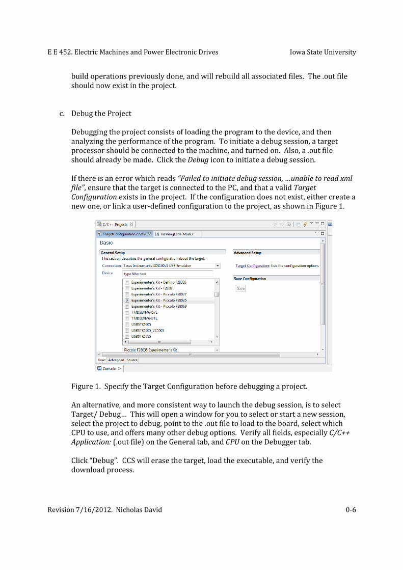
If there is an error which reads “Failed to initiate debug session, …unable to read xml
file”, ensure that the target is connected to the PC, and that a valid Target
Configuration exists in the project. If the configuration does not exist, either create a
new one, or link a user-defined configuration to the project, as shown in Figure 1.
Figure 1. Specify the Target Configuration before debugging a project.
An alternative, and more consistent way to launch the debug session, is to select
Target/ Debug… This will open a window for you to select or start a new session,
select the project to debug, point to the .out file to load to the board, select which
CPU to use, and offers many other debug options. Verify all fields, especially C/C++
Application: (.out file) on the General tab, and CPU on the Debugger tab.
Click “Debug”. CCS will erase the target, load the executable, and verify the
download process.

E E 452. Electric Machines and Power Electronic Drives Iowa State University
Revision 7/16/2012. Nicholas David
0-7
The debugger view will open showing which project is loaded, which device is
connected, and the status of the device, as shown in Figure 2. You can also verify
that the board is working by checking the Disassembly window. If the target is
connected, there should be assembly code displayed here. The pointer should be at
the start of the main routine.
Figure 2. The Debug perspective can show device and program status, current
location in the assembly code, and other things not shown here.
If you click “Reset”, the address should go to a different location. To run the code,
click “Resume”. The program will start running; status of Device/ Thread[main]
should say “Running”. If you refresh the disassembly view, all data should
disappear, because the device is running the program. If you click “Halt”, the
disassembly window will show where in the code the program is at when you halted
it. If you select “Go Main”, the program will go back to the start of the program and
resume running.

E E 452. Electric Machines and Power Electronic Drives Iowa State University
Revision 7/16/2012. Nicholas David
0-8
4. Embedded Coder
Embedded Coder provides a graphical means of programming the F28035 MCU. A
Simulink block diagram is compiled and an executable file is generated to run on the
target device. Although Embedded Coder is designed for use with CCSv4, it is used here
with CCSv5.
a. Install Embedded Coder
Prerequisites: TI Code Generation Tool v5.2.2
https://www-a.ti.com/downloads/sds_support/
TICodegenerationTools/index.htm
Obtain a license file for Embedded Coder. If using a license server, manually place
an updated license in the server. Otherwise, open
MATLAB/Help/Licensing/Activate Software. License management is handled
through the MATLAB website, within a user’s account settings.
If the Embedded Coder toolbox is already installed, activating the license is all that is
necessary to allow use of Embedded Coder. If Embedded Coder is not installed, do
so now.
b. Verify Embedded Coder Installation
Verify that Embedded Coder is installed using the command “ver”. Verify that the
license for Embedded Coder is valid, by typing the command “license checkout
RTW_Embedded_Coder”. If the license is valid, MATLAB should return “1”. Verify
that the license is in use by typing the command “license inuse”. MATLAB should
return “matlab, rtw_embedded_coder”. It is not necessary to checkout the license
for each use. The license should checkout automatically when using any component
of Embedded Coder.
c. Verify CCS Installation via MATLAB
Environment variables are used by MATLAB to specify the locations of resources.
The variables are actually defined in Windows. Access them by right-clicking My
Computer/Properties/Advanced Settings/Environment Variables…
Note: “checkEnvSetup” should be used anytime CCS is configured to run with a new
board or processor, or if any upgrades are made to third party tools, such as the
compiler.

E E 452. Electric Machines and Power Electronic Drives Iowa State University
Revision 7/16/2012. Nicholas David
0-9
Type the command “checkEnvSetup('ccsv4', 'F28035', 'check')” to check if the
currently installed tools match the requirements of the system. Even though CCSv5
is the IDE being used, MATLAB is setup as if it were using CCSv4. The return from
the command will be different, depending on the requirements of the specified IDE
and target device. A typical return is shown in Figure 3.
Figure 3. MATLAB return to check the environment setup for Embedded Coder.
For some tools, it is okay to have a more recent version than that which is listed in
the requirements; for others, it is not. The “Code Generation Tool” is one of those
tools which must match.
Note: The “Code Generation Tools” and “DSP/BIOS”, that are available by default via
the CCS installation, are too recent. The “Actual Code Composer Studio version” is
not displayed; this is okay. Also, the “Flash API version” is populated even though
its environment variable is not displayed; this is also okay. It is not necessary to set
the FLASH_API variable to the location of the utility.
If the environment variables are not populated, check that the variable exists in the
Windows Environment Variables. If it does not exist there, add the variable and
type the directory location similar to those which already exist. It should not be

E E 452. Electric Machines and Power Electronic Drives Iowa State University
Revision 7/16/2012. Nicholas David
0-10
necessary to change anything in the setup. Do not use the command
“checkEnvSetup('ccsv4', 'F28035', 'setup')” to specify the tool locations; only use the
Windows Environment Variables.
d. Setup the xMakefile Utility to support Code Generation
The xMakefile is a utility in MATLAB used to specify which tools are used to build
the software. Various configurations are already set for TI devices, based on the
environment setup described previously. For detailed help, see MATLAB
Help/Embedded Coder/User’s Guide/Embedded IDEs and Embedded
Targets/Working with Texas Instruments Code Composer Studio v4/Tutorial:
Using Makefiles with Code Composer Studio v4.x.
Enter the command “xmakefilesetup” to specify the xMakefile configuration; this
takes a minute to load. A screenshot of the utility is shown in Figure 4. Select
“ticcs_C2000_ccsv4”. Check that the tool directories are correct. Click “Apply”.
A window should appear to select the CCS installation directory; point to
C:\CCSv5\ccsv5. The Tool Directories tab should populate information for the Code
Generation Tool, Compiler, and DSP/BIOS tools. Click “OK”; the configuration is now
operational.
Figure 4. xMakefile utility to specify the location of Code Generation Tools.
Note: For help setting up Embedded Coder, navigate to Help/Embedded
Coder/User’s Guides/ Embedded IDEs and Embedded Targets/Working with Texas
Instruments Code Composer Studio v4 IDE/Getting Started.

E E 452. Electric Machines and Power Electronic Drives Iowa State University
Revision 7/16/2012. Nicholas David
0-11
5. Building a Program with Embedded Coder
Open MATLAB/Simulink and set the Current Folder to a non-network location. To use a
student’s U:\ drive, navigate to the location through “Computer”; do not use the default
“Network” location.
a. Configure the Model
Open a new model. Add the Target Preferences block. This block configures the
model to generate code for your target. Without this block, several changes to the
Simulation Configuration Parameters would be necessary. Set the IDE Tool Chain to
Texas Instruments Code Composer Studio v4 (makefile generation only). Select the
board TI F28035. No other changes should be necessary. Click “OK”.
The model preferences block should be located at the highest level of the model for
which code will be generated. By placing the block at the highest level of the
Simulink model, the entire model will be built and compiled. If the preferences
block is at the highest level of a subsystem, code will only be generated for that
subsystem.
Go to Simulation Configuration Parameters. Ensure the Solver is set for Fixed-Step,
Discrete, Auto step size. The Hardware Implementation tab should show Texas
Instruments C2000, Little Endian. No changes should be necessary. Go to the Code
Generation tab. Ensure System Target File is idelink_ert.tlc. No changes should be
necessary. Expand the Code Generation tab and go to Report. Check the box to
create a Code Generation Report, Code-to-model. Go to the IDE Link tab. Set Build
Action to Build. No other changes should be necessary. Click “Apply”, and “OK”.
Add blocks as needed to perform a task. Be aware that not all blocks are compatible
with code generation; see MATLAB Help/Simulink Coder/User’s Guide/Model
Architecture and Design/Modeling/Supported Products and Block Usage for more
information.
b. Build the Model
Build the model by going to Tools/Code Generation/Build Model, or
Simulation/Configuration Parameters…/Code Generation tab and click “Build”.

E E 452. Electric Machines and Power Electronic Drives Iowa State University
Revision 7/16/2012. Nicholas David
0-12
If you receive an error while building the makefile which reads:
“The call to idelink_ert_make_rtw_hook, during the exit hook generated the
following error:
Error while building the project.
The build process will terminate as a result.”
it is likely that the compiler is outside of the specified range. The compiler must be
between v5.2.1 and v5.2.3. Use “CheckEnvSetup…” to verify the compiler. Code
Generation Tools are available from TI at
http://processors.wiki.ti.com/index.php/Compiler_Releases.
As MATLAB is building code for the project, watch the Command Window for any
errors or warnings. All files built for the program will be installed in a newly
created folder, within the “Current Folder” specified in MATLAB. The new folder
will be called “project_ticcs”, where “project” is the name of the model. This folder
contains all files required by Code Composer Studio, including the .out executable
file which will be downloaded to the target device.

E E 452. Electric Machines and Power Electronic Drives Iowa State University
Revision 7/16/2012. Nicholas David
0-13
6. Managing Code Generation Tools
Code Composer Studio is configured to use a default compiler supplied with the
installation, though many others are available for download. When they are
downloaded, it is necessary to specify their location within CCS. If the Code Generation
Tool is changed in CCS, it will be necessary to re-run the “checkEnvSetup('ccsv4',
'F28035', 'check')” command and verify the MATLAB configuration.
a. View Available Compilers
To view available Code Generation Tools, open CCSv5, and navigate to
Window/Preferences/CCS/Build/Code Generation Tools. Select one of the
discovered tools; v6.0.1 is the default, and might only be selected because the Target
Configuration File is currently set to a F28035 device. For more information on
compiler selection and installation, go to
http://processors.wiki.ti.com/index.php/Compiler_Installation_and_Selection.
b. Download a New Compiler
To add a new compiler, go to https://www-
a.ti.com/downloads/sds_support/TICodegenerationTools/index.htm and
download a different version; a myTI login will be required. Go to “Downloads” and
select the desired compiler. Fill out the form for approval and wait for a download
button to appear. If the download doesn’t work, send an email as suggested by the
“Download Failed” page.
The download is a .exe file. Run this file as an administrator, from the desktop, and
install in C:\CGT, as shown in Compiler_Installation_and_Selection, available at
http://processors.wiki.ti.com/index.php/Compiler_Installation_and_Selection.
Ensure that the Windows Environment Variable TMP has a specified location. If this
is not set, the compiler will not function correctly, as described in DefectHistory.txt,
which is included with the compiler download.
c. Setup CCS to Use the New Compiler
To use the new compiler to generate code for a project, open CCSv5 and navigate to
Window/Preferences/Build/Code Generation Tools, and click to “Add” a new path.
Discovered Tools will populate. Make your selection and click “Apply” to save the
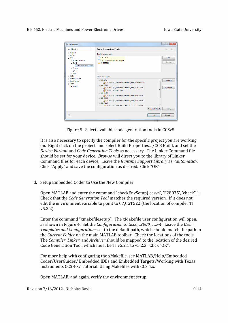
path, as shown in Figure 5.
E E 452. Electric Machines and Power Electronic Drives Iowa State University
Revision 7/16/2012. Nicholas David
0-14
Figure 5. Select available code generation tools in CCSv5.
It is also necessary to specify the compiler for the specific project you are working
on. Right click on the project, and select Build Properties…/CCS Build, and set the
Device Variant and Code Generation Tools as necessary. The Linker Command file
should be set for your device. Browse will direct you to the library of Linker
Command files for each device. Leave the Runtime Support Library as <automatic>.
Click “Apply” and save the configuration as desired. Click “OK”.
d. Setup Embedded Coder to Use the New Compiler
Open MATLAB and enter the command “checkEnvSetup('ccsv4', 'F28035', 'check')”.
Check that the Code Generation Tool matches the required version. If it does not,
edit the environment variable to point to C:\CGT522 (the location of compiler TI
v5.2.2).
Enter the command “xmakefilesetup”. The xMakefile user configuration will open,
as shown in Figure 4. Set the Configuration to ticcs_c2000_ccsv4. Leave the User
Templates and Configurations set to the default path, which should match the path in
the Current Folder on the main MATLAB toolbar. Check the locations of the tools.
The Compiler, Linker, and Archiver should be mapped to the location of the desired
Code Generation Tool, which must be TI v5.2.1 to v5.2.3. Click “OK”.
For more help with configuring the xMakefile, see MATLAB/Help/Embedded
Coder/UserGuides/ Embedded IDEs and Embedded Targets/Working with Texas
Instruments CCS 4.x/ Tutorial: Using Makefiles with CCS 4.x.
Open MATLAB, and again, verify the environment setup.

E E 452. Electric Machines and Power Electronic Drives Iowa State University
Revision 7/16/2012. Nicholas David
0-15
e. Change Environment Variables (if needed)
When changing an Environment Variable, DO NOT use blank spaces in any paths
names, i.e. use “MyPath” or “my_path” instead of “my path”. An example of setting
the path to code generation tools is shown in Figure 6.
Figure 6. Windows Environment Variables are used to specify the path of code
generation tools.
Depending on the particular ControlSUITE installation, the file path names may
vary. Make sure the path in the Environment Variable matches the actual path
exactly, and that the same naming convention is used; i.e. “\” instead of “/”.
Note: Changing the Environment Variable to the path of the v1.0.0 F28035 Flash
API, does not result in a match of the required and actual versions; this is not a
problem. Embedded Coder will still generate code and the .out file for the device
based on the xMakefile configuration.