investigation of friction modelling and elastic tooling ...420597/fulltext02.pdf · investigation...
TRANSCRIPT
Master Thesis
Master programme of Simulation of Manufacturing Processes Department of Engineering Science
May, 2011
Investigation of Friction Modelling and Elastic Tooling influences on the Springback Behaviour in Sheet Metal Forming Analysis Wei Chen

MASTER THESIS
i
Investigation of friction modelling and elastic tooling influences on the spring back behavior in sheet metal forming analysis
Summary
Sheet metal forming is one of the most common forming processes used in the industry,
especially in the automotive industry. It becomes a common sense, that by increasing the
accurate simulation of sheet metal forming, the industry can save dramatic cost in trial-and-
error process when designing the sheet metal forming tools. In past decades, considerable
studies have been done in the field of numerical analysis of metal forming processes,
particularly in springback prediction. Significant progresses have been made, but the
accuracy of simulation results still needs to improve. One reason is that, in the typical sheet
metal forming analysis the tools are considered as absolute un-deformable rigid bodies. The
deformation of the tools, which happens in the real production, is not taken into account.
Another reason may be that the classic simulation considers the friction coefficient
between the tools and blank as constant. However, the actual friction condition depends
on a number of parameters.
The objective of this thesis work is trying to investigate how it will affect the springback
prediction results when either the tool deformation or more complex friction conditions
are considered. The purpose is nothing related with the precise simulation about the true
problem or how accuracy the simulation results show compared to the experiment results.
The work is only to give an emphasis hint that how the FE-model and friction mode
chosen affects the springback results when doing a numerical analysis.
A simple model called flex rail is used for sheet metal forming simulations with three
different friction models. A comparison between the results clearly shows a difference
when advanced friction models are applied. A 3D elastic solid model is created to compare
the result with rigid model. The results show the difference when deformation of the tools
is taken into account. Finally, an actual case with tools from the industry is investigated.
The tools are from SAAB Cars Body Components. This case is to investigate the possibility
and necessity of applying the advanced friction model and elastic tools when a complex real
industry problem is faced. Further study is needed to do with comparison experimental
data to verify the accuracy when these models are used.
Date: May, 2011 Author: Wei Chen Advisor: Mats Larsson Examiner: Kenneth Eriksson Programme: Simulation of manufacturing processes Education level: Advanced Main field of study: Mechanical Engineering Credits: 30HE credits Keywords Springback, friction model, elastic tools , sheet metal forming Publisher: University West, Department of Engineering Science
S-461 86 Trollhättan, SWEDEN Phone: + 46 520 22 30 00 Fax: + 46 520 22 32 99 Web: www.hv.se
Investigation of friction modeling and elastic tooling influences on the springback behavior in sheet metal forming analysis
ii
Preface
This report is the result of my master thesis project in programme of Simulation of
Manufacturing Processes at the Department of Engineering Science of University West.
The work was initiated by and carried out at SAAB Automation and Production
Technology Center (PTC) of University West during the winter 2010 to spring 2011.
I would like to express my appreciation to my supervisor Mats Larsson for all the help and
guidance during the work of this master thesis. I would also like to thank Farhan Khan and
other people at PTC for the help and understanding. Appreciation also is expressed here to
all the staff at Saab Automobile AB who gave the help and support. Finally, I would like to
appreciate my family and friends for all their support.
Trollhättan Sweden, May 2011
Wei Chen

Investigation of friction modeling and elastic tooling influences on the springback behavior in sheet metal forming analysis
iii
Table of Contents
Summary............................................................................................................................. i
Preface ............................................................................................................................... ii
Symbols and glossary ......................................................................................................... v
1 Introduction................................................................................................................. 1 1.1 Background......................................................................................................... 1 1.2 Overview of previous works ............................................................................... 2
1.2.1 Introduction to the springback prediction ............................................... 2 1.2.2 Introduction to the friction modelling..................................................... 3 1.2.3 Introduction to elastic tool modelling ..................................................... 4
1.3 Objective ............................................................................................................ 5 1.4 Disposition ......................................................................................................... 6 1.5 Delimitation ........................................................................................................ 6
2 Methodology................................................................................................................ 7 2.1 Method overview ................................................................................................ 7 2.2 Geometry............................................................................................................ 8 2.3 Software for the project ...................................................................................... 9 2.4 Evaluation of springback .................................................................................. 10
3 Theory ....................................................................................................................... 10 3.1 Yield criteria...................................................................................................... 10 3.2 Time integration scheme ................................................................................... 12 3.3 Friction models and application ........................................................................ 13
3.3.1 Coulomb Friction Model ...................................................................... 13 3.3.2 V02 friction model ................................................................................ 14 3.3.3 Halmstad friction model ....................................................................... 15
4 Parameters study of the two advanced friction models ............................................... 17 4.1 Friction modal v02............................................................................................ 17 4.2 Halmstad friction model ................................................................................... 22
5 Simulation using different friction models.................................................................. 22 5.1 Model description ............................................................................................. 22 5.2 General simulation setup................................................................................... 23 5.3 Comparison of the results ................................................................................. 23
5.3.1 Punch force .......................................................................................... 24 5.3.2 Blank thickening ................................................................................... 25 5.3.3 Effective strain of the blank up surface ................................................. 26 5.3.4 Springback analysis ............................................................................... 27
6 Simulations using rigid versus elastic tools ................................................................. 29
6.1 FE models ........................................................................................................ 29
6.2 General setup.................................................................................................... 31
6.2.1 Elements............................................................................................... 31 6.2.2 Process parameters ............................................................................... 31
6.3 Comparison of the results ................................................................................. 32
6.3.1 Forming loads ....................................................................................... 32
6.3.2 Drawing-in............................................................................................ 33
6.3.3 Blank thickening ................................................................................... 33
6.3.4 Deformation of the tools ...................................................................... 34
6.3.5 Springback analysis ............................................................................... 35

Investigation of friction modeling and elastic tooling influences on the springback behavior in sheet metal forming analysis
iv
7 Simulation with the SAAB tools................................................................................. 36
7.1 FE-model.......................................................................................................... 36
7.2 Simulation with different friction models .......................................................... 38
7.2.1 General setup........................................................................................ 38
7.2.2 Comparison of the springback results ................................................... 38
7.3 Simulation using rigid versus elastic models ...................................................... 39
7.3.1 General setup........................................................................................ 39
7.3.2 Comparison of the results ..................................................................... 40
8 Methods to decrease simulation time for elastic tools........................................... 41
8.1 Deformable Rigid Bodies .................................................................................. 41
8.2 Coupling of different meshes ............................................................................ 42
9 Discussion and conclusion ......................................................................................... 43
9.1 Different friction model simulation................................................................... 43
9.2 Elastic tools versus rigid tools simulation .......................................................... 44
References ....................................................................................................................... 45

Investigation of friction modeling and elastic tooling influences on the springback behavior in sheet metal forming analysis
v
Symbols and glossary
FEM Finite element method
HSS High strength steel
DP Double precision
SMP Symmetric Multi-Processing
MPP Massively Parallel Processing
DOF Degree of freedom

Investigation of friction modeling and elastic tooling influences on the springback behavior in sheet metal forming analysis
1
1 Introduction
This chapter gives the background and base knowledge and outcome of the literature study
for the work.
1.1 Background
Along with the intensifying of environmental problems and energy crisis, reducing gas
consumption to save energy has become the most important issues for auto-making
industry. The proportion of high strength steel (HSS) used in auto-making is gradually
increasing to serve the purpose of decreasing the weight of automobiles which is the most
effective way to reduce gas consumption to address the energy and environmental
problems. So the trend of increasing use of high and ultrahigh strength steel for bodies in
white is obvious.
However, one of the main obstacles is their unknown behaviour in metal forming
processes. HSS has a very high material yield stress, which requires using a very high force
as well as high strength tools to form parts, and these parts will have large elastic recovery
after forming. Traditionally, tools are made as stiff as possible, which generate higher costs
for individual tools. It is clear though, that a tremendous amount of money could be saved
by designing the tools such, that their elastic deformation during the forming process is
considered. Subsequently the tool geometry may then be designed to compensate the
elastic deformations. This would lead to lighter and hence less expensive tools.
In past years, numerical simulation by finite element method (FEM) has become a
powerful tool to help avoiding the undesirable defects in materials technological processing,
as the accuracy of predicting defects encountered in sheet metal forming has been
improved dramatically. Many studies have been devoted to improve the numerical
simulation of sheet metal forming processes and springback phenomenon encountered
after forming. It comprises several directions of research: developing of new types of finite
elements, considering materials anisotropy, developing new time-integration schemes for
forming and springback stages, and introducing new constitutive models that provide a
more realistic description of the material behaviour [1]. In this work, new friction models
have been applied to investigate the influences of friction modelling on springback
behaviour in sheet metal forming analysis.

Investigation of friction modeling and elastic tooling influences on the springback behavior in sheet metal forming analysis
2
1.2 Overview of previous works
1.2.1 Introduction to the springback prediction
In sheet metal forming, the shape of the blank obtained at the end of the forming step
closely conforms to the tools’ geometry. However, as soon as the loads are removed,
elastically-driven change in the blank shape takes place. This process is termed springback
[2]. As is described, the phenomenon of springback introduces a deviation between the
desired shape and the obtained one, which results in assembly problems. Therefore, in the
product design process, it is necessary to perform an extensive and iterative experimental
trial-and-error process to determine the tools’ geometry and other variables, which will
enable a product of the required shape. As a result, the lead time and costs of production
are increased considerably. Increasing the accuracy of prediction of springback is a
common goal of the whole manufacturing industry. In past decades, a lot of research
proposals have been issued to study the factors which influence the springback behaviours
in sheet metal forming. From the results of previous studies, there is a general sense that to
be able to efficiently and precisely use finite element software to predict springback in sheet
metal forming, springback needs to be considered as a complex physical phenomenon,
which is very sensitive to numerous factors. Since springback is a complicated
phenomenon, it is always difficult to conclude a standard cause of the discrepancy between
the magnitudes of springback obtained in simulation and reality, especially when the
product geometry is complicated [3]. Springback phenomenon in metals depends on
various parameters: variation of elastic properties of a material; elastic-plastic anisotropy;
material hardening. If finite element modelling is employed for analysis of springback the
accuracy of the obtained solution is significantly affected also by the factors that control
the quality of simulation of the forming operation. The most important of these include the
method of unloading, time integration scheme, choice of element, blank and tool
discretization and contact algorithm (see figure 1.1) [2].
Investigation of friction modeling and elastic tooling influences on the springback behavior in sheet metal forming analysis
3
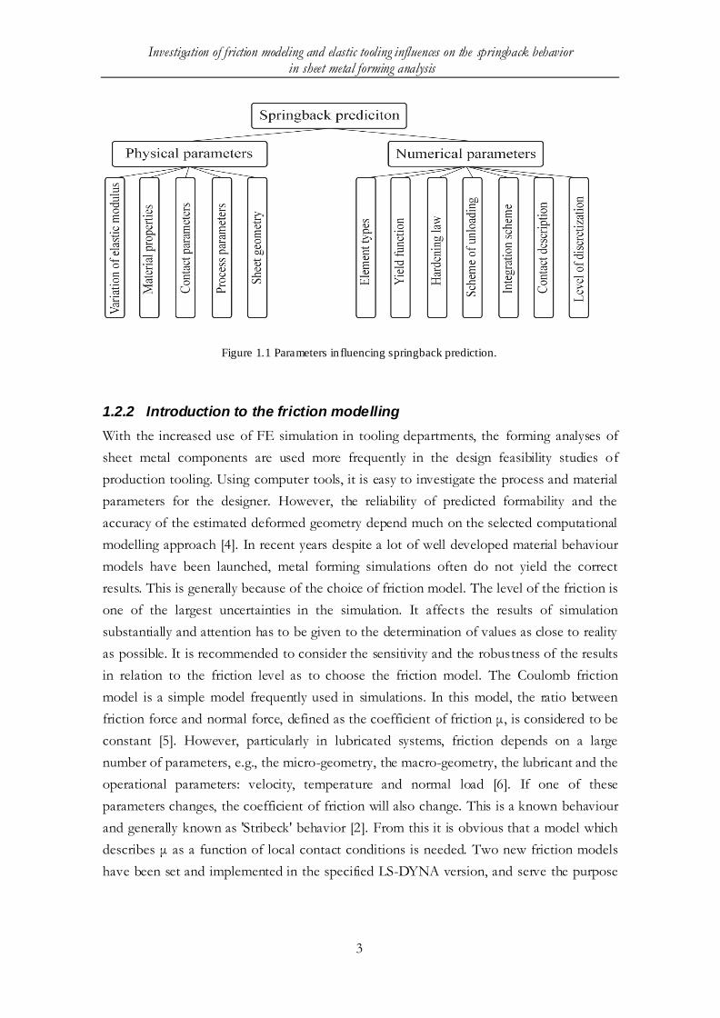
Figure 1.1 Parameters in fluencing springback prediction.
1.2.2 Introduction to the friction modelling
With the increased use of FE simulation in tooling departments, the forming analyses of
sheet metal components are used more frequently in the design feasibility studies of
production tooling. Using computer tools, it is easy to investigate the process and material
parameters for the designer. However, the reliability of predicted formability and the
accuracy of the estimated deformed geometry depend much on the selected computational
modelling approach [4]. In recent years despite a lot of well developed material behaviour
models have been launched, metal forming simulations often do not yield the correct
results. This is generally because of the choice of friction model. The level of the friction is
one of the largest uncertainties in the simulation. It affects the results of simulation
substantially and attention has to be given to the determination of values as close to reality
as possible. It is recommended to consider the sensitivity and the robustness of the results
in relation to the friction level as to choose the friction model. The Coulomb friction
model is a simple model frequently used in simulations. In this model, the ratio between
friction force and normal force, defined as the coefficient of friction μ, is considered to be
constant [5]. However, particularly in lubricated systems, friction depends on a large
number of parameters, e.g., the micro-geometry, the macro-geometry, the lubricant and the
operational parameters: velocity, temperature and normal load [6]. If one of these
parameters changes, the coefficient of friction will also change. This is a known behaviour
and generally known as 'Stribeck' behavior [2]. From this it is obvious that a model which
describes μ as a function of local contact conditions is needed. Two new friction models
have been set and implemented in the specified LS-DYNA version, and serve the purpose

Investigation of friction modeling and elastic tooling influences on the springback behavior in sheet metal forming analysis
4
of investigation of friction modelling influences on the springback behaviour in sheet metal
forming analysis in this work.
1.2.3 Introduction to elastic tool modelling
As the trend of increasing use of high and ultrahigh strength steel becomes noticeable,
thereby, how to reduce the stiffness of tool to save the tool production cost is the common
goal of the manufacturing industry. However, reducing the stiffness of the forming tools
adds also new challenges to the modelled forming system, because in that way, elastic
deformations of the press equipment, i.e. the frame, table and the base foundation need to
be taken into account. One possible approach is of course to model the whole press
equipment by finite elements to research elastic response in detail [7]. In the same time, it
must be also taken into account that the modelling effort may be very huge. Moreover
usual engineering assumptions, which might already influence the results very much, need
to be implemented. In other words, it might be much easier to do a limited number of real
world stiffness measurements of the machine that can in turn be used as boundary
conditions [7] (see Figure 1.2). The final step is to reduce the model size further to reduce
the degrees of freedom (DOF) of the modelled tools, i.e. die, and punch and binder (see
Figure 1.3). In overview of previous works, there are some possible approaches available in
LS-DYNA to take elastic response of tools in finite element sheet metal forming
simulations into account. They are namely so called deformable rigid bodies, elastic super
elements and full 3D discretization of respective geometries. Details how this could be
done have been discussed in [7]. Therefore, it should be emphasized that a modular setup
for such forming simulations which take the elastic deformation of tools into account can
be possibly achieved. Standard elastic stiffness parameters for each press combined with
standard discretization techniques for the tools help to simplify the rather complex setup
[7].

Investigation of friction modeling and elastic tooling influences on the springback behavior in sheet metal forming analysis
5
Figure 1.2 Reduction of model: Press. [7]
Figure 1.2 Reduction of model: Tools. [7]
1.3 Objective
The purpose of this thesis is to investigate whether the springback behaviour is affected by
the friction modelling in the simulation of sheet metal forming analysis. And how the
springback behaviour appears when the deformation of tool surfaces is taken into account.

Investigation of friction modeling and elastic tooling influences on the springback behavior in sheet metal forming analysis
6
Some investigation and testing of available methods to decrease the needed computer
capacity will be tried based on the information given in some referenced paper.
Finally, an investigation will be made on an actual case with tools from SAAB Cars Body
Components, which including deformation of tools and advanced friction model could
identify the problem in a much more complex geometry in the actual production case.
Although this work is not supposed to get a clearly generalized answer with only one
material studied, some gross conclusions can be collected that whether the advanced
friction modelling should be applied when springback analysis with simple geometry.
Especially the conclusion can be gathered that, when high press force anticipated, geometry
like “Header Upper”, if the elastic tools always are needed to be able to predict the
springback behaviour.
1.4 Disposition
The methodology used in this work will be described after this introductory chapter. Then
theory of the friction models, elastic tooling model and some numerical parameters used in
simulations will be given. After this, a simple model called flex rail is used for sheet metal
forming simulations with different friction models and with either elastic tooling. The
results from these simulations are compared. Some of the methods to decrease the
simulation time in the case of elastic tools are also mentioned. The last chapter describes
the case with the tools received from SAAB. The springback results with different models
are compared to investigate how the results will be affected when it is applied to the
complex real industry geometries. The workflow includes description from meshing the
models for FE simulations to post-processing the simulation results.
1.5 Delimitation
Due to limitations in condition and time, it has been not possible to verify the numerical
analysis results by comparing to corresponding experiment data. So the accuracy of the
springback prediction needs to be tested further.
There are several methods found in the literature and subsequently described in this thesis
for how to decrease the simulation time when elastic tools are included. However, due to
the time limitation, we have not been able to get these methods to work as desired. So, in
this work, only the total 3D discretized mesh method is used.
Investigation of friction modeling and elastic tooling influences on the springback behavior in sheet metal forming analysis
7
2 Methodology
In this chapter, methodology is described as follows.
2.1 Method overview
Since the virtual prediction of springback behavior in sheet metal forming processes
includes many different parameters, this work is focused on friction model and elastic tool
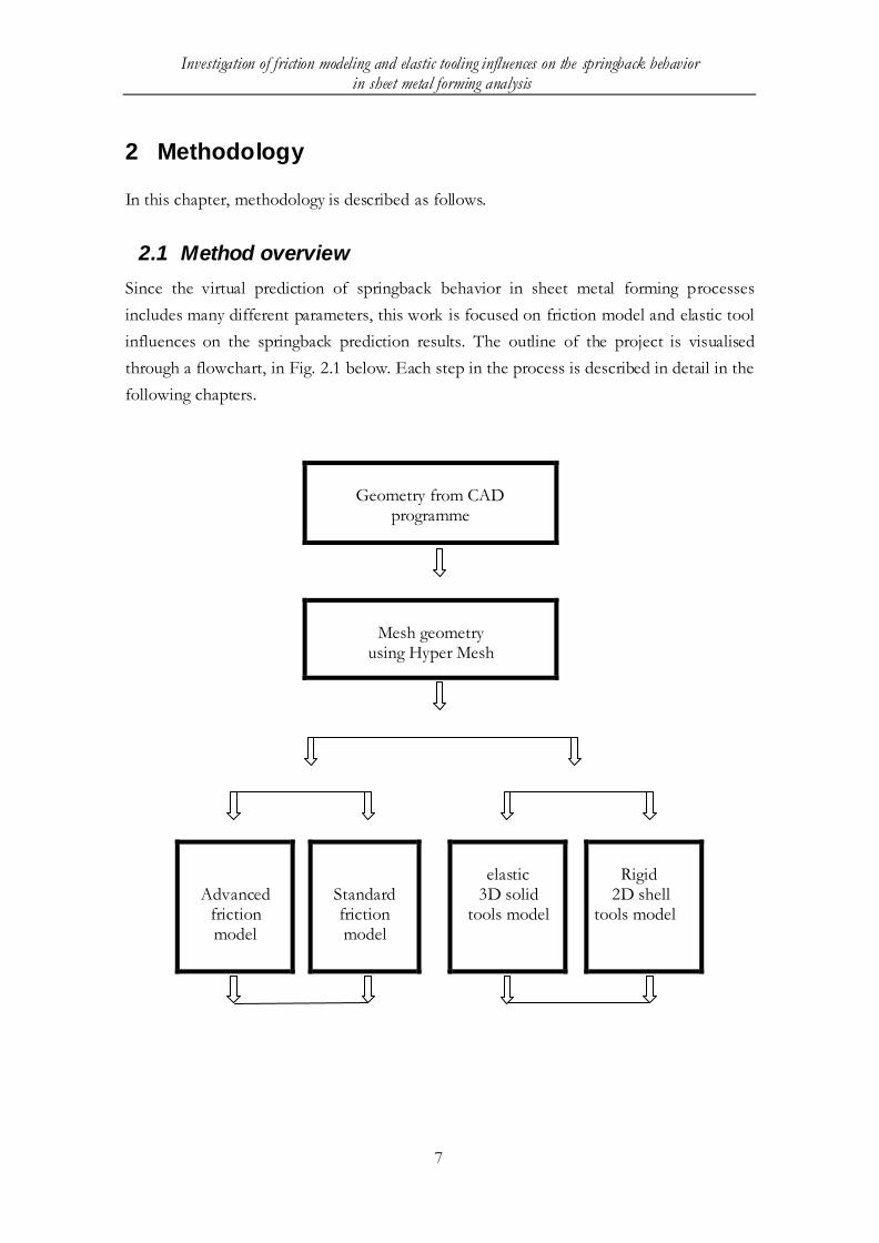
influences on the springback prediction results. The outline of the project is visualised
through a flowchart, in Fig. 2.1 below. Each step in the process is described in detail in the
following chapters.
Geometry from CAD
programme
Mesh geometry
using Hyper Mesh
Advanced friction model
Standard friction model
elastic
3D solid tools model
Rigid
2D shell tools model

Investigation of friction modeling and elastic tooling influences on the springback behavior in sheet metal forming analysis
8
Use LS-DYNA to analyse the
forming problem and output the dynain file
Use LS-DYNA to analyse the
springback problem and compare the results
Fig. 2.1 Flowchart of the project outline
2.2 Geometry
Within this project, two different geometries have been studied.
A flexible semi-industrial part called “Flex rail”, which was developed for
researching simulation of forming processes. The geometry is shown in Fig. 2.2.
The second geometry is a Saab Automobile tool for a part called “Header Upper”
shown in Fig 2.3. This part is upgraded and compared to the existing one in the
new Saab 9-5.
Fig. 2.2 Geometry of Flex rail

Investigation of friction modeling and elastic tooling influences on the springback behavior in sheet metal forming analysis
9
The “Flex rail” geometry was chosen because of its highly flexible characteristic and simple
geometry which, however, could generate a complex springback behaviour representing
b-pillars and side members of automobiles [1]. With this geometry not only three different
positions with different strain states of the blank material have been studied but also details
of how the different variations of friction models and elastic tool modelling should be
decided.
Fig. 2.3 Geometry of Head upper from SAAB car
For the “Header Upper” component, it is positioned up to the windshield glass, just in
front the car roof. This component is designed as strong as possible to protect the people
in car when a crash accident happens.
"V02" and "Halmstad" are friction models implemented in LS-DYNA as part of the
ongoing research program "Simupart", which is delivered by Saab Automobile during the
autumn 2010. "V02" is modelled by Daniel Wiklund and Swerea IVF, "Halmstad" is
modelled by Hans Löfgren Högskolan Halmstad, and both of them are still under
development.
Both of the two geometries, the simple one “Flex rail” or the complex one “Header Upper”
have been used to analyse the influence of both elastic tool modelling and advanced
friction modelling on the springback behaviours.
2.3 Software for the project
A number of softwares have been utilized in this project. Main of them will be described
below.
LS-DYNA special version with new friction model implemented is used to
calculate the forming and springback process.

Investigation of friction modeling and elastic tooling influences on the springback behavior in sheet metal forming analysis
10
LS-PREPOST is applied to analyse the results from the calculation cluster and get
the animated phase picture.
Hypermesh is used to mesh the parts and create the 3-D solid model when the
elastic tool model is applied.
When the standard friction model is applied, MPP LS-DYNA version with double
precision (DP) is used as the default version. While the special friction model V02 and
Halmstad model was implemented in SMP LS-DYNA release 4.2 with single precision (SP)
and SMP LS-DYNA release 4.2.H double precision respectively.
2.4 Evaluation of springback
For the geometry “Flex rail”, in order to achieve a similar process between FE simulations
and physical experiments, the punch and blank-holder forces were measured during the
experiments. Furthermore, strains were evaluated with an optical system, Argus (2007). For
better presentation of the strain states, three different positions were chosen. The
springback of physical experiment was evaluated. The detailed description can be found in
[2]. With this information from the experiments the FE model parameters are finally set.
The results are compared between both two friction models and elastic and rigid tool
models, and then conclusions can be proposed for how the friction model and elastic tool
influence the springback results for simple geometry like “Flex rail”.
For “Header upper” geometry, since this kind of part geometry includes a lot of complex
features and manufactured in big size, so gravity influence should be taken into account
when doing springback analysis. The analysis process follows steps like: gravity→ forming
→ coarsening → springback. Different friction models, elastic and rigid tools model are
also applied, difference of the results can be collected through the comparison among the
different models to get a conclusion with complex geometry like “Header upper”.
3 Theory
3.1 Yield criteria
It is well known that, due to the manufacturing process, cold-rolled metal sheets get
different plastic properties in the rolling, the transverse, and the thickness directions,
respectively. And this initial anisotropy has a significant influence on the strain and stress
distribution during forming of these sheet metals. Besides, the sheet metal is also subjected
Investigation of friction modeling and elastic tooling influences on the springback behavior in sheet metal forming analysis
11
to the deformation-induced anisotropy. Due to the microstructure evolution, this induced
anisotropy destroys the symmetry of the initial anisotropy. However, since the magnitude
of the strains during a normal sheet forming operation is moderate, the influence of the
deformation- induced anisotropy is normally neglected compared to the initial one in sheet
forming simulations[8]. In last decades numerous yield criteria have been proposed, which
can fulfil the industrial demands regarding accuracy, easy parameter identification, and
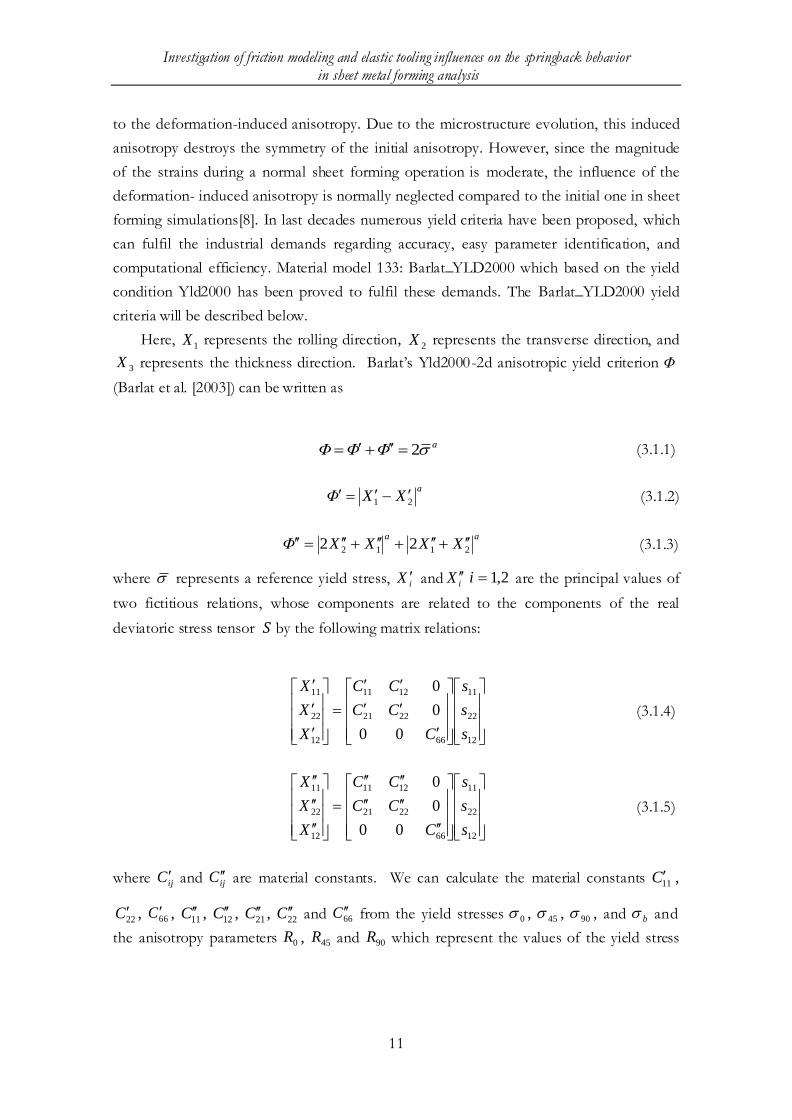
computational efficiency. Material model 133: Barlat_YLD2000 which based on the yield
condition Yld2000 has been proved to fulfil these demands. The Barlat_YLD2000 yield
criteria will be described below.
Here, 1X represents the rolling direction,
2X represents the transverse direction, and
3X represents the thickness direction. Barlat’s Yld2000-2d anisotropic yield criterion Φ
(Barlat et al. [2003]) can be written as
aΦΦΦ 2 (3.1.1)
a
XXΦ 21 (3.1.2)
aa
XXXXΦ 2112 22 (3.1.3)
where represents a reference yield stress, iX and iX 2,1i are the principal values of
two fictitious relations, whose components are related to the components of the real
deviatoric stress tensor 𝑆 by the following matrix relations:
12
22
11
66
2221
1211
12
22
11
00
0
0
s
s
s
C
CC
CC
X
X
X
(3.1.4)
12
22
11
66
2221
1211
12
22
11
00
0
0
s
s
s
C
CC
CC
X
X
X
(3.1.5)
where ijC and ijC are material constants. We can calculate the material constants 11C ,
22C , 66C , 11C , 12C , 21C , 22C and 66C from the yield stresses 0 , 45 , 90 , and b and
the anisotropy parameters 0R , 45R and 90R which represent the values of the yield stress

Investigation of friction modeling and elastic tooling influences on the springback behavior in sheet metal forming analysis
12
and R when the tensile axis is at 0 , 45 , and 90 from the rolling (1X ) direction and bR
represents the in-plane strain ratio 12 in the equal biaxial tension test, respectively.
3.2 Time integration scheme
In LS-DYNA, the two main solution procedures for the simulation of sheet forming
processes are the dynamic explicit and the static implicit algorithms. The dynamic explicit
method is frequently used in simulations of sheet forming processes, since it reduces the
computation time drastically compared to implicit methods, using a diagonal mass matrix
to solve the equations of motion [9–11]. A disadvantage of this method is the conditional
stability, necessitating extremely small time steps or artificial adaptations to the model. The
static implicit method is unconditionally stable, but a linear set of equations must be solved
repeatedly. The common basis of both methods is the discretized equation of motion [12]:
𝑀𝑑 + 𝐹𝑖𝑛𝑡 = 𝐹𝑒𝑥𝑡 (3.2.1)
where 𝑑 , intF and extF are the nodal accelerations, the internal forces and the external forces
respectively. Since the internal force vector is a function of nodal displacements and
accelerations, equation 3.2.1 are a non-linear equation in displacements, velocities and
accelerations. Thus, a time integration algorithm must be used to solve this set of
differential equations.
The Newmark integration method is an efficient and commonly used single-step
integration algorithm. It establishes the relation between the state variables of the current
state and the state to be calculated. The basic steps of the Newmark method are [12]:
𝑑𝑛+1 = 𝑑𝑛 + ∆𝑡𝑑 𝑛 + ∆𝑡2( 1
2 − 𝛽 𝑑 𝑛 + 𝛽𝑑 𝑛+1 (3.2.2)
𝑑 𝑛+1 = 𝑑 𝑛 + ∆𝑡( 1 −ϒ 𝑑𝑛 + ϒ𝑑 𝑛+1 (3.2.3)
where n is the time increment and the parameters β and γ are free to choose. If β ≠0, the
displacement at time 𝑡𝑛+1 is a function of its own time derivatives and the integration
scheme is called implicit. An iterative procedure is needed to solve the system of equations
3.2.1. The second term becomes equal to 𝐹𝑖𝑛𝑡 = 𝐾𝑢𝑛+1 , where K is the stiffness matrix. In

Investigation of friction modeling and elastic tooling influences on the springback behavior in sheet metal forming analysis
13
order to iteratively solve the equations of equilibrium the computat ion of the stiffness
matrix is required.
If β= 0, the displacement at time 𝑡𝑛+1 is a function of variables from a previous step and
therefore the integration scheme is called explicit. In this case the system of equations 3.2.1
is linear and its solution is trivial. It is important to mention that the explicit integration
scheme is conditionally stable, which mean that the time increment must be less than a
critical value. For linear solid elements this value can be approximated by the smallest time
needed for an elastic wave to cross one element [12].
The major advantage of an explicit method is its easy and straightforward calculation.
There are no unbalance forces between the external and internal forces, which determine
the values of nodal accelerations at the start of every time increment. So, the explicit
method does not suffer from the convergence problems without the balance forces. The
major disadvantage of this method is its conditional stability and prohibitively small
maximum allowable time step. Usually time mass scaling is employed to serve the purpose
of decreasing the total computation time. In this way the critical time step is enlarged by
artificially increasing the mass of the material.
The implicit time integration method is unconditionally stable, and a time increment can be
selected based on the required accuracy and the convergence behaviour. In this way, the
iterative solution procedure is used to find the state variables that satisfy the equilibrium of
every increment time step, which gives more reliable results. The main disadvantage of this
algorithm is that the computation time for large models is significant, and sometimes
reaching convergence within a time increment takes a lot of effort.
3.3 Friction models and application
3.3.1 Coulomb Friction Model
The easiest and probably the most well known friction model is the Coulomb friction
model. Though it greatly over simplifies the frictional phenomena, it is widely used to
describe the friction in mechanical contacts.
The friction between two contact partners is based on the Coulomb formulation in LS-
DYNA. The behaviour of friction condition is based on the parameters on
*CONTACT_ …card 2: static and dynamic friction coefficients, exponential decay
coefficient, and coefficient for viscous friction. The interface force is updated by the
underlying frictional algorithm to a trial value first, and then it computes the tangential part,
the coefficient of friction and the yield force, and finally determines the frictional force.
Investigation of friction modeling and elastic tooling influences on the springback behavior in sheet metal forming analysis
14
This is equivalent to an elastic-plastic spring model [13]. The friction coefficient is
calculated using the following formula:
/r nf f (3.3.1.1)
where rf denotes
the shear force and nf denotes the normal force.
The Coulomb friction law is only valid as long as the true contact area increases
proportional with the normal force. Many investigations have shown, that such a relation
can only be observed for relatively small normal forces. Beyond this, the increase of the
true contact area is smaller than the increase of the applied force. This is due to the fact,
that the true contact area cannot become greater than the geometric contact area.
3.3.2 V02 friction model
In LS-DYNA the standard algorithm can be modified for some specification via the
keyword *USER_INTERFACE_FRICTION, which invokes the subroutine defined by
the user.
The friction model of V02 is based on the well known Wiklund model, which considers
properties of surface topography, lubricant, sheet material, and process parameters such as
sliding speed and pressure. The boundary friction level in this model was held constant and
the behaviour of the boundary lubrication is partly based on empirical data from test with
DP600 material. The main theory is presented as followed. More information about the
model presents in [14-16].
In this model equilibrium of surface loads is evaluated, i.e. if the blank holder (apparent
load ( AP ) and the shared load on peaks ( PP ) and pressurised lubricant film ( HP ) are
balancing each other
(1 )A P HP P P
(3.3.2.1)
The normal force ( NF ) is partly carried by the surface peaks ( PF ), and partly by the
lubricant ( LF )
N P LF F F (3.3.2.2)
Let ( ) be the fraction of contact, (A) the apparent area and ( HP ). The generated
hydrodynamic pressure, then:
(1 )L HF P A (3.4.2.3)

Investigation of friction modeling and elastic tooling influences on the springback behavior in sheet metal forming analysis
15
If assume the velocity of lubricant with no-slip at each wall, then tangential force 𝐹𝑇 can be
expressed as friction force on peaks and shear stress of lubricant
0 0(1 ) (1 ) /T P P fF F A F A h
(3.3.2.4)
Where μ0 is the friction in boundary lubrication and fh is the functional gap.
Furthermore, let AP be the apparent pressure, and then friction can be expressed as
0
(1 ) (1 )[1 ]T H
N A A f
F P
F P P h
(3.3.2.5)
If the pad bearing theory [17] is used to express the hydrodynamic pressure generated in
the lubricant
*
2
6H
f
B WP
h
(3.3.2.6)
Where (6W*) is the load coefficient [17], and B is the total width of bearings. Finally, the
friction can be expressed as
0 2
(1 ) 6 * (1 )[1 ]
A f A f
B W
P h P h
(3.3.2.7)
In the LS-DYNA manual, there is also general introduce. When this model is applied, the
IFID under *USER_INTERFACE_FRICTION must be same as CID under
*CONTACT_.., in that way, it can be linked in corrected way. Under *CONTACT_…..
there is a parameter for static friction (𝑓𝑠). The number given can only be used by the
model when the relative glide velocity equals 0.
3.3.3 Halmstad friction model
An implementation of a user defined frictions model for DP600 also known as the
"Halmstad model" has been made in the latest version of LS-DYNA (R4.2.H). Halmstad
model is a local friction model. The friction shear stress τ (parallel to the sliding direction)
is given by the local contact pressure p. For the plate DP 600, the relation is as following.

Investigation of friction modeling and elastic tooling influences on the springback behavior in sheet metal forming analysis
16
For 1.5h
𝑝 = 𝑝𝑐 ℎ + 𝑝𝑣 ℎ ⇒ ℎ
𝜏 = µ𝑐 ∙ 𝑝𝑐 ℎ + µ𝑣 ℎ ∙ 𝑝𝑣 ℎ ⇒ 𝜏
(3.3.3.1)
and when 1.5h
𝜏 = 𝜇𝑐 ∙ 𝑝 (3.3.3.2)
where
𝜇𝑐 = 0.11 (Friction factor in the boundary layer area) (3.3.3.3)
𝜇𝑣 = 2.54 ∙ 10−8 ∙ 𝑒2.13ℎ + 5.74 ∙ 10−3 ∙ 𝑒0.486ℎ (3.3.3.4)
𝑝𝑐 ℎ = 𝐻 ∙ 0.245 ∙ 𝑒−(ℎ−0 .745
1 .18)2
(3.3.3.5)
𝑝𝑐 ℎ =𝜂𝑉
𝜎∙ 774 ∙ 𝑒−(
ℎ+2 .09
2 .91)2
(3.3.3.6)
Where h denotes dimensionless oil film thickness; η denotes dynamic whisper [Pas]
V denotes sliding speed [m/s] σ denotes surface standard deviation. H expresses hardness
[Pa]. When this model invoked by * USER_INTERFACE_FRICTION, the model has
four (4) definable parameters given in the keyword. The USRFRC in
*CONTROL_CONTACT must set to four (4). Under keyword
* USER_INTERFACE_FRICTION, the input parameters, number of history variables
NOC, number of variables to be initiated NOCI, number of parameters per entry segment
NHSV all must be set to four(4).More information is presented in [18,19]

Investigation of friction modeling and elastic tooling influences on the springback behavior in sheet metal forming analysis
17
4 Parameters study of the two advanced friction
models
As mentioned above, the two advanced friction models consider all the tribological
conditions of the stamping process, and take into account lubricant properties, roughness
of tool and sheet, and local contact conditions such as speed and pressure. When these
models are applied, in addition to the static friction coefficient, several other parameters are
needed as input. In this chapter, we study how these parameters affect the friction results
of these models, in other words, how these factors which are taken into account, from the
standpoint of the new friction modal, affect the friction of stamping process forward affect
the springback. Each parameter is studied through varying the value 20% to check how it
affects the friction. The simple flex rail geometry is used.
4.1 Friction modal v02
In this friction model, there are seven definable parameters which are involved with yield
strength of the sheet material, dynamic viscosity of the lubricant oil, and roughness of the
sheet and tools surface, tool anisotropic and direction and so on. Several of these
parameters are studied how they affect the contact friction respectively. In all of the cases,
one of the contact interfaces between die and blank is taken as the study item.

Investigation of friction modeling and elastic tooling influences on the springback behavior in sheet metal forming analysis
18
Fig. 4.1.1 Friction energy as function of time of different lubricant oil dynamic viscosity
Investigation of friction modeling and elastic tooling influences on the springback behavior in sheet metal forming analysis
19
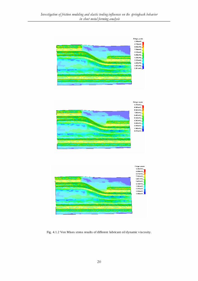
The yield strength of the plate surface is used to calculate the effective contact area in this
model which depends on the material used and the coating layer on the sheet surface. More
details may be found in [14]. The lubricants oil dynamic viscosity of 2.9E-8 Pas with
varying 20% up and down to 3.48E-8 and 2.32E-8 are used to study. In the figure 4.1.1,
total friction energy as function of time of different lubricant oil dynamic viscosity is
compared. The results show that, there is no much different in total friction energy and the
history of friction energy increasing with different lubricant oil dynamic viscosity. Figure
4.1.2 and figure 4.1.3 show the von Mises stresses and shell thickness of each case. From
the results no big differences can be found among the different cases. Similar analysis also
have done to other parameters, there is a gross conclusion that can be gained, the factors
considered in the V02 friction model are not sensitive to the value applied, in other words,
there is not a separate parameter this model importantly relies on. How the influence of
this model on springback will be talked about later in this work, however, the effect by
each factor should be discussed related to the theory background in the future.
Investigation of friction modeling and elastic tooling influences on the springback behavior in sheet metal forming analysis
20
Fig. 4.1.2 Von Mises stress results of different lubricant oil dynamic v iscosity.

Investigation of friction modeling and elastic tooling influences on the springback behavior in sheet metal forming analysis
21
Fig. 4.1.3 Shell thickness results of different tool anisotropic and direction
Investigation of friction modeling and elastic tooling influences on the springback behavior in sheet metal forming analysis
22
4.2 Halmstad friction model
There are four definable parameters in this friction modal which are involved with
hardness of the sheet material, dynamic viscosity of the lubricant oil, surface standard
deviation and friction factor in the boundary layer area. Here the same parameter study as
the previous model has been done. The results show the same conclusion, not single
parameter has an outstanding effect on this model. How the combination of all the
involved factors effect on springback phenomena in each model will be studied in the next
chapter.
5 Simulation using different friction models
In this chapter, previously mentioned three friction models, Coulomb, V02 and Halmstad
models, are applied respectively. The influence of each model on the springback and
forming process is studied. The flex rail geometry is used. All the process conditions are
identical except the applied friction model among different cases.
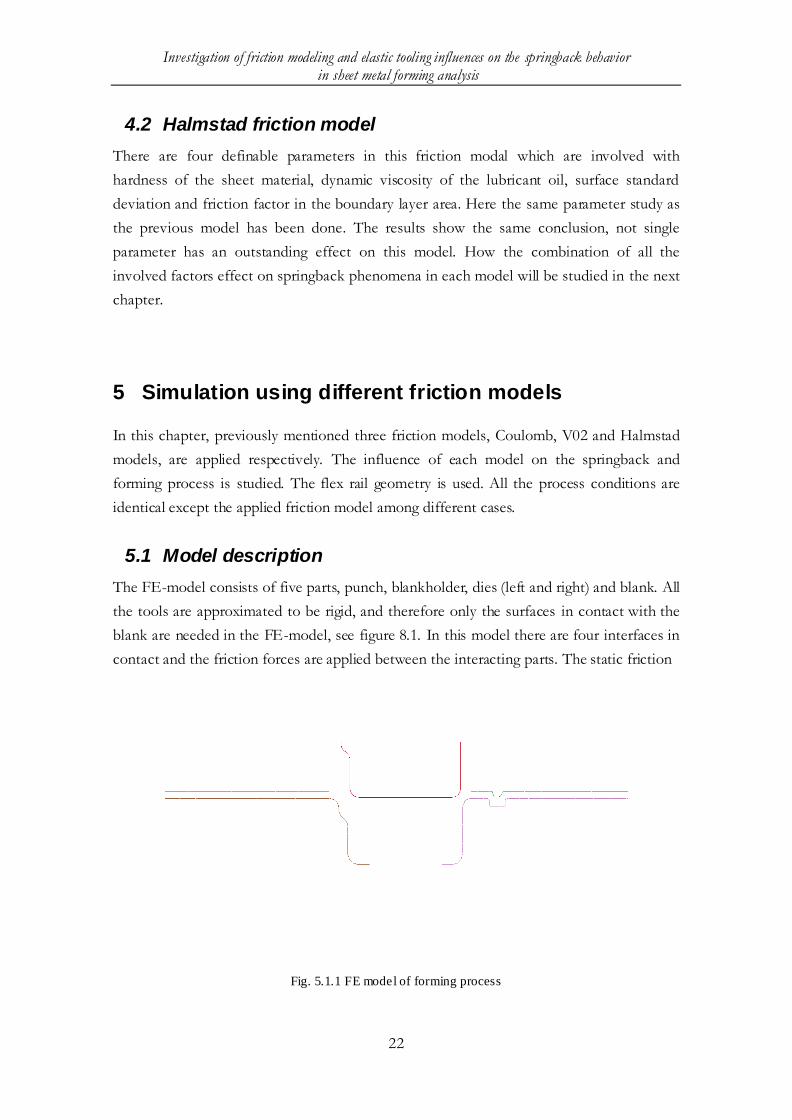
5.1 Model description
The FE-model consists of five parts, punch, blankholder, dies (left and right) and blank. All
the tools are approximated to be rigid, and therefore only the surfaces in contact with the
blank are needed in the FE-model, see figure 8.1. In this model there are four interfaces in
contact and the friction forces are applied between the interacting parts. The static friction
Fig. 5.1.1 FE model of forming process

Investigation of friction modeling and elastic tooling influences on the springback behavior in sheet metal forming analysis
23
coefficient is set to 0.129, which is applied in the Coulomb friction model and other two
advanced friction models only when the relative gliding velocity equals 0. A nonlinear
analysis must be performed, since the blank is subjected to large strains. In sheet metal
forming, the impact time is short and the time step will therefore be very small to ensure
accurate solution. The most suitable approach for the forming process analysis is the
explicit time integration, where many uncoupled equations are solved simultaneously. As to
the springback analysis, usually implicit time integration is chosen.
5.2 General simulation setup
The objective of the case is to give an accurate enough result that can tell the influences of
different friction model when applying in sheet metal simulation. In order to avoid noise
effects as much as possible, the process parameters are input as simple as possible. To set
up the simulation, the guidelines in Input Parameters for Metal Forming Simulation using
LS-DYNA [20] and Input Parameters for Springback Simulation using LS-DYNA [21]
were used.
As mentioned, all tool parts are modelled as rigid shell elements. The die is constrained in
both displacement and rotation in all directions in the global coordinates, while the punch
and blankholder are allowed to be translated in the z direction, see figure 5.1.1. The blank is
modelled as material type 133. This model is ruled by yield function Barlar_yield2000. The
elements used in blank sheet are fully integrated shell elements.
The contact between interfacing surfaces are modelled by using a penalty method. This
penalisation reduces any residual between the two surfaces that are to be in contact, by
multiplying it by some penalty factor, which thereby works like a spring in-between the two
surfaces. A “CONTACT_FORMING_ONE_WAY_SURFACE_TO_SURFACE”
type of contact is used. The application of the two advanced models is presented in chapter
3.
The simulation of the actual forming process is performed as a so-called multi-forming
simulation, which starts by the blankholder closing and fixating the blank to draw beads of
the die. After the blankholder motion, the punch motion starts. Notice that, there is no
gravity loading, because of the blank sheet is perfect flat.
5.3 Comparison of the results
The results of forming and springback simulations of the three friction models are
compared in this chapter.

Investigation of friction modeling and elastic tooling influences on the springback behavior in sheet metal forming analysis
24
5.3.1 Punch force
Fig. 5.3.1 Punch force vs punch stroke in three models .
From the result, the punch force in z direction along the punch stroke files are obtained
and investigated. In Figure 5.3.1 the forces history along the stroke are compared. As
shown, the forces are almost identical in the three simulations during the forming process.
This fact shows that when the binder load and punch velocity and travel distance is
specified, the forming loads in these three friction models are the same.

Investigation of friction modeling and elastic tooling influences on the springback behavior in sheet metal forming analysis
25
5.3.2 Blank thickening
The results of simulation show that, the two advanced friction models have different
thickness distribution compared to coulomb model, and the coulomb model seems to yield
more local thickening than the other two. Between the two advanced model V02 and
Halmstad model, there is not much difference noticed in the results except the smallest
thickness value of the blank. The results are shown in fig.5.3.2. (Fringe value scaled)
Fig. 5.3.2 Blank thickness of simulation in Coulomb, V02 and Halmstad friction model (from left to right
respectively)

Investigation of friction modeling and elastic tooling influences on the springback behavior in sheet metal forming analysis
26
5.3.3 Effective strain of the blank up surface
From the results of simulation, U-surface effective strain is studied. In the figure 5.3.3
(Fringe value scaled), it can be noticed that, in the coulomb model, the blank yield the
largest effective strain and in the halmstad model, the blank yield the smallest effective
strain.
Fig. 5.3.3 Effective strain of blank up surface in Coulomb, V02 and Halmstad friction model (from left to
right respectively)

Investigation of friction modeling and elastic tooling influences on the springback behavior in sheet metal forming analysis
27
5.3.4 Springback analysis
The springback was evaluated over the whole surface, but in order to present the
comparison among the results clearly, three sections were selected to present the
springback results for the three models, which is shown in figure 5.3.4. Section A is located
at the area with step, section B is selected in the radius area where the step ends, while the
section C is chosen at the area far away from the step and radius.
Implicit springback analysis required rigid body motions eliminated by defining constraints
since dynamic inertia effects are not included in a static analysis. Without constraints, a tiny
applied load would cause the entire work piece to move rigidly an infinite distance without
creating any stresses [21]. Proper constraints must be defined to eliminate six rigid body
motions in the model – three translations and three rotations, and the model can deform
freely without developing any reaction forces at the constraint points. The usual method is
to constrain selected translational degrees of freedom at three nodes, see the details in [21].
Fig. 5.3.4 Evaluated sections
The springback results were then used to study the effect of the variation in the friction
model in the FE simulation of the forming processes. Figure 5.3.5 to 5.3.7 show compared
results from simulations of processes in three sections respectively. It is obvious from these
figures that different prediction results of springback are obtained when different friction
models are applied.
From these figures, it can be noticed that, in this case coulomb friction model over predict
the springback compared the other two models. While v02 and halmstad model get nearly
the same result.
From figure section A and section B, through comparison the results of springback
between the left and right sides of the final shape, a conclusion can be got that the right
side appears less springback than the left side, which means that, the feature of the step
prevents the springback in this area. The result of section C also verifies this, the

Investigation of friction modeling and elastic tooling influences on the springback behavior in sheet metal forming analysis
28
amplitudes of the springback in the right side increase because this area is far away from
the step seen in figure 5.3.4.
Fig. 5.3.5 Springback results in section A
Fig. 5.3.6 Springback results in section B

Investigation of friction modeling and elastic tooling influences on the springback behavior in sheet metal forming analysis
29
Fig. 5.3.7 Springback results in section C
6 Simulations using rigid versus elastic tools
6.1 FE models
A simple geometry called “flex rail” which is modelled as both rigid and elastic model is
performed to investigate the differences in springback results affected by the deformation
of the tool surfaces.
The die and the blankholder are modelled using solid elements while for simplification the
punch is modelled using rigid shell elements, because die and blankholder usually suffer
much more deformation than the punch. All the solid elements are 4 node-tetra elements
and shell elements are 4 node-quadrilaterals. The FE model for this test is shown in Figure
6.1.1. The aim of this case is to find out how much the deformations of the elastic tool will
affect the blank springback results.
Number of elements
Die: 167687 solid elements
Blankholder: 78154 solid elements
Punch: 36920 shell elements
Investigation of friction modeling and elastic tooling influences on the springback behavior in sheet metal forming analysis
30
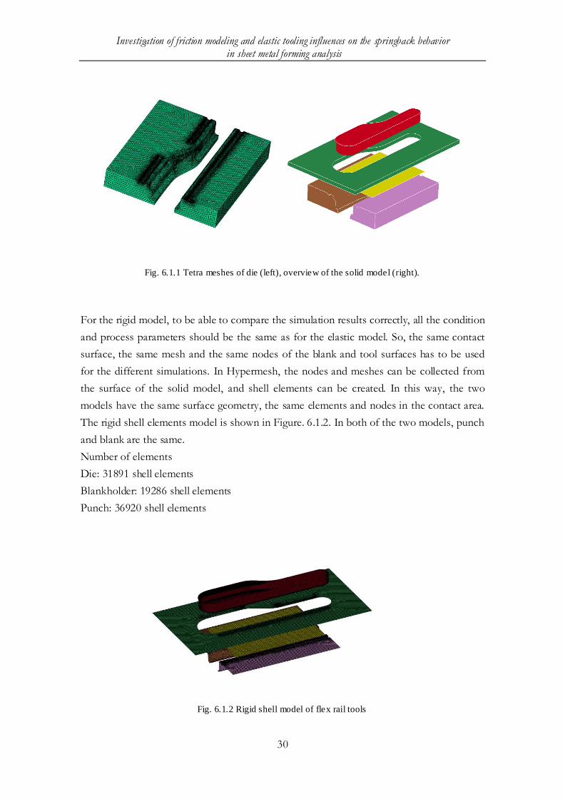
Fig. 6.1.1 Tetra meshes of die (left), overview of the solid model (right).
For the rigid model, to be able to compare the simulation results correctly, all the condition
and process parameters should be the same as for the elastic model. So, the same contact
surface, the same mesh and the same nodes of the blank and tool surfaces has to be used
for the different simulations. In Hypermesh, the nodes and meshes can be collected from
the surface of the solid model, and shell elements can be created. In this way, the two
models have the same surface geometry, the same elements and nodes in the contact area.
The rigid shell elements model is shown in Figure. 6.1.2. In both of the two models, punch
and blank are the same.
Number of elements
Die: 31891 shell elements
Blankholder: 19286 shell elements
Punch: 36920 shell elements
Fig. 6.1.2 Rigid shell model of flex rail tools

Investigation of friction modeling and elastic tooling influences on the springback behavior in sheet metal forming analysis
31
6.2 General setup
6.2.1 Elements
Considering the deformation of the tools, elements thickness should take into account. 3 -D
solid mesh is applied in this case. The solid element types considered for this project were
hexahedron and tetrahedron elements. Hexahedron elements are elements with six sides
and eight nodes. Tetrahedron elements are elements with four sides and four nodes.
Figures of these two types of element are shown below.
Fig. 6.2.1 Hexahedron element Fig. 6.2.2 Tetrahedron element
In order to avoid the noisy effect by the element choice, both hexahedron and tetrahedron
meshes are tried on this “flex rail” model. We found that the forming results with these
two types of elements were similar, but the calculation time decreases dramatically with
tetra compared to hexa-elements. Hexahedron meshing is also time consuming and much
more effort taken to set up in comparison with tetrahedron meshing, especially considering
the complex geometry of the car component “head upper” meshing later. Given that the
results were similar and the processing time were noticeable shorter when using
tetrahedron mesh, we decided to use tetrahedron mesh for 3D tools in this case. The mesh
generated for the die tool can be seen in fig 6.1.1. As mentioned up, for the rigid punch
and blank elements, there is no other better choice than quadrilateral.
6.2.2 Process parameters
This case aims at investigation of the influence of tool surface deformation on the
springback behaviour. So the deformation of the tool is brought into analysis, elastic
material model type 01 is applied to the tool. As simple as possible, the standard friction
model is used. When defining the boundary constraint and loading force, much more effort
is needed than we thought. When rigid tools are used as common way, the movement

Investigation of friction modeling and elastic tooling influences on the springback behavior in sheet metal forming analysis
32
boundary condition is just applied to the entire part and the force is only loaded at the
geometry centre of the rigid part, and then LS-DYNA automatically distribute the
boundary constrain. While the elastic 3D elements model is used, considering the un-
uniform deformation distribution through the thickness direction, the movement boundary
constrain and loading force have to be applied on the surface of the tools node by node.
For the die, the bottom surface nodes have to be constrained the freedom degree in the z-
direction and the three rotation degree to model the foundation condition. For the
blankholder, the boundary movement and blankholder force are applied on the up surface
nodes. Other process parameters are input in the same way as the previous case.
6.3 Comparison of the results
6.3.1 Forming loads
In order to make sure that the including of elastic tools does not affect the forming loads,
the rcforc files are obtained and investigated. Even if the binder load and the punch
velocity and travel distance are the same in the simulations, there could be a risk that the
forces involved in the forming process would differ. In Figure 6.3.1 the punch forces in z
direction in rcforc file are compared. As shown, the forces are almost identical in the two
simulations during the forming process. Moreover the blankholder forces and two die
forces are also compared and the results are almost identical. This fact shows that the
forming loads for simulations using rigid and elastic tools are the same. In other words, the
possibility that the changed loading forces in the process may affect the results can be
eliminated.
Fig. 6.3.1 Punch force as function of process time

Investigation of friction modeling and elastic tooling influences on the springback behavior in sheet metal forming analysis
33
6.3.2 Drawing-in
Figure 6.3.2 shows the differences in draw-in between elastic and rigid tool models. From
the results, the largest difference is found at the long side, where the difference is 2.827mm.
Fig. 6.3.2 Comparison of the blank draw-in, with the rig id tool forming as red and the elastic tool
forming as blue
6.3.3 Blank thickening
The fringe value of the figure is scaled to make it clear to compare the blank thickness
distribution. From figure 6.3.3, it shows different blank thickness distribution between two
models. It seems like that the simulation with the rigid tool yield more local thickening than
the model with elastic tools.
Figure 6.3.3: Blank thickness. Simulat ion with elastic tools to the left and rig id tools to the right

Investigation of friction modeling and elastic tooling influences on the springback behavior in sheet metal forming analysis
34
6.3.4 Deformation of the tools
Usually, when performing the sheet metal forming analysis, tools are always considered as
rigid bodies, which means, the tools are un-deformable, see figure 6.3.4 a. However, for the
real product, tools are deformable see figure 6.3.4 a. The tiny local deformation of the tool
surface may affect the stress distribution of the blank result. Given the same loading
condition, the deformation of the tools should be the factor which affects the blank draw-
in and thickening, which have been shown.
Figure 6.3.4 a: Plastic strain of the rigid d ies
Figure 6.3.4 b : Plastic strain of the elastic b lankholder (left) and elastic dies (right)

Investigation of friction modeling and elastic tooling influences on the springback behavior in sheet metal forming analysis
35
6.3.5 Springback analysis
The three sections (figure 5.3.4) are used to present the springback results. From picture
6.3.5.a to picture 6.3.5.c, the springback results of rigid and elastic model in these three
sections are compared. In the first two figures, we can notice that, the rigid model over
predicts the springback compared to the elastic model. While on the right side of section C,
the springback amplitude of the blank with elastic model seems to be much bigger than the
one with rigid model. Further study should be done to make sure the stress distribution
around this area. However, from the results shown in these figures, it appears clear that,
when the deformation of tools is taken into account, there is noticeable change in the
results of springback prediction.
Fig. 6.3.5.a. Springback results in section A
Fig. 6.3.5.b. Springback results in section B

Investigation of friction modeling and elastic tooling influences on the springback behavior in sheet metal forming analysis
36
Fig. 6.3.5.c. Springback results in section C
7 Simulation with the SAAB tools
In the following chapter the deformation of tools received from SAAB Car Body
Components, which is called “head upper” will be investigated. This part is upgraded and
compared to the existing one in the new Saab 9-5. With these tools, the previously studied
friction models are applied. Simulation results are compared to check how the friction
models influence springback results when a complex geometry is considered. To investigate
the deformation of real productive tool, two simulations are made, one where the tools are
modelled as rigid, and one where 3D-elastic tools model are used.
7.1 FE-model
CAD model of the tools are exported from the software Autoform, the specified
simulation tool for car components manufacturing in SAAB Automobile, which considers
all the tools as rigid bodies. Because of some characteristic of this software, only die can be
exported, which is in IGES format. The other parts like punch, blankholder, which are
used in this FE-model, are obtained through offsetting parts of the die using Hypermesh.
For simplification and also base of the previous study, tetrahedron elements are used to
mesh the solid tools except the punch, which is modeled as rigid shell body. The 3D
models of die and blankholder are shown below.

Investigation of friction modeling and elastic tooling influences on the springback behavior in sheet metal forming analysis
37
Fig. 7.1.1 3D-Meshed die
Fig. 7.1.2 3D-Meshed blankholder
As with the flex rail model explained earlier in this thesis, shell elements are created from
the solid model surface.

Investigation of friction modeling and elastic tooling influences on the springback behavior in sheet metal forming analysis
38
Fig. 7.1.3 FE-model of rigid 2D model
7.2 Simulation with different friction models
7.2.1 General setup
As to focus on the friction model analysis, for simplification, only the rigid shell FE-model
is used. The starting point of this case is the gravity loading process. It is important when
the flat, stress-free blank under its own weight after being placed on the binder surface
over the die cavity, especial for the large shape and flexible blank. In LS-DYNA, it is
convenient to operate a gravity analysis just including several keyword commands. More
information is presented in [22]. The general setup refers to previous description in chapter
5. However, in this simulation, the die and blankholder are moving along z-direction, while
the punch is fixed.
7.2.2 Comparison of the springback results
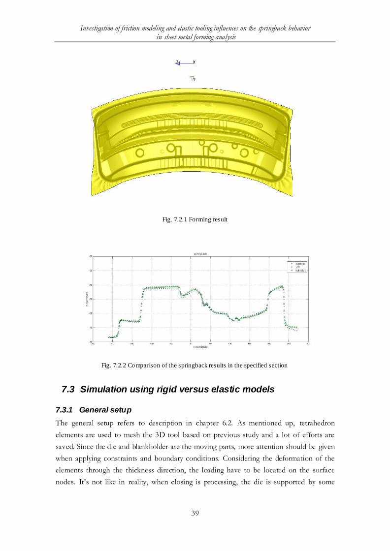
The forming result (Coulomb) without trimming is shown in figure 7.2.1. In order to show
the comparison results the three models clearly, a section also is chosen, see figure 7.2.1. In
the figure, we can notice that, friction model V02 and Halmstad almost have identical
results, while compared to Coulomb model, the prediction results differ.
Investigation of friction modeling and elastic tooling influences on the springback behavior in sheet metal forming analysis
39
Fig. 7.2.1 Forming result
Fig. 7.2.2 Comparison of the springback results in the specified section
7.3 Simulation using rigid versus elastic models
7.3.1 General setup
The general setup refers to description in chapter 6.2. As mentioned up, tetrahedron
elements are used to mesh the 3D tool based on previous study and a lot of efforts are
saved. Since the die and blankholder are the moving parts, more attention should be given
when applying constraints and boundary conditions. Considering the deformation of the
elements through the thickness direction, the loading have to be located on the surface
nodes. It’s not like in reality, when closing is processing, the die is supported by some

Investigation of friction modeling and elastic tooling influences on the springback behavior in sheet metal forming analysis
40
structure applying the support forces. While in simulation, the boundary condition of
drawing parts is always prescribed as motion. So, it takes a lot of efforts to avoid
penetration and the dynamic effects when closing the binder and applying the loading force.
7.3.2 Comparison of the results
Contacting forces are compared to make sure the forming loads are the same.
Fig. 7.3.1 Identical forming loading between elastic and rigid mode

Investigation of friction modeling and elastic tooling influences on the springback behavior in sheet metal forming analysis
41
The same section is chosen as before to show the springback results. The result is
presented in figure 7.3.2. From the result, we can notice that, in some region, it seems like
the rigid tool has more punch stroke. This might cause from the deformation of the die
surface. So it is obvious that, when the elastic tool is used, the results change significantly.
Fig. 7.3.2 Comparison of the springback results in the specified section
8 Methods to decrease simulation time for elastic
tools
Compared to classic rigid tool set up, the reasons why elastic tools not are included in the
simulation are the increased calculation time, higher demand for memory and much more
effort in meshing. In order to avoid these mentioned disadvantages, several methods have
been developed.
8.1 Deformable Rigid Bodies
Modal analysis is well known in linear dynamic analysis for efficient computations of the
response of elastic structures. The method is to find a particularly useful problem
dependent basis called eigenmodes. Compared to standard direct methods, where the
response node is the analysis item, modal methods represent the response of the structure
modes.
Deformable rigid bodies, or flexi rigid bodies, is a method which is based on calculation of
the eigenmodes behaviour of the structure. If a complete set of modes is used, the method
can be considered as a transformation into a set of generalized coordinates, see figure 8.1.
Typically, only a small number of modes are used, in other words, only interesting ones are

Investigation of friction modeling and elastic tooling influences on the springback behavior in sheet metal forming analysis
42
included. So, this method becomes an approximate and simplified solution which means a
substantial computational saving.
Fig. 8.1 Eigenmodes of the structure [23]
The method is performed in two phases. In the first phase, eigenmodes are obtained by
making an eigenmodes simulation and output to a binary database. In the second phase,
this database is used as input to supply modes for the transient dynamic analysis. This
method has been tested in several studies and has been proved to give a similar solution as
the one obtained from a full direct solution. The results also show that the accuracy of this
method is related to the number of modes included. With more modes included, the
deformation of the body is better approximated than with lesser modes. Usually, as advised
in [24], six rigid body modes from the structural modes are separated by choosing the
separation frequency between the sixth and the seventh eigenfrequency. The
implementation of the method into LS-DYNA has been described in [25].
8.2 Coupling of different meshes
When investigating elastic response of forming tools, it appears that only small
deformation happened on the tool surface location, which means that a fine resolution of
the tool deformation is probably not necessary. Only the fine surface details demand a
rather fine mesh. This method is to apply a fine surface shell mesh on the contact surfaces
and use a coarse solid element to mesh the structure, see figure 8.1. The fine surface shell
elements will work as contact segments on the coarse 3D meshes. The total of elements of
the tool model and efforts of meshing can be decreased tremendously since the coarse 3D
mesh is used. In LS-DYNA, the contact interface option of tied-offset-contact now is
available to fix nodes from the fine surface mesh to corresponding segments from the
coarse 3D mesh. However further investigation should be issued on the accuracy of this
method since with this method the local deformation is neglected.

Investigation of friction modeling and elastic tooling influences on the springback behavior in sheet metal forming analysis
43
Fig. 8.2 Coupling of different mesh [23]
9 Discussion and conclusion
9.1 Different friction model simulation
As is well known, in most cases of sheet metal forming analysis, the friction between two
contact partners is based on a Coulomb formulation, which is equivalent to an elastic-
plastic spring model. However, lots of studies have proved that, the tribological conditions
of the stamping process are more complex. Main reason for simplification of the complex
condition is to save the cost. Another reason could be the limit of calculation in the
specific time. Obviously, the simplification will decrease the accuracy of simulation. In this
way, it might increase the cost of time and money in a trail-and-error process. So how to
balance this contradiction is an interesting topic. One objective of this thesis work is to
investigate how much the different friction model chosen in simulation affects the
springback prediction.
Two advanced user defined friction models which consider the tribological conditions
more complex are applied to compare with Coulomb model. First the simple geometry
“flex rail” is used to test. The results of the two advanced friction models appear
significantly different to the classic friction model. Considering the geometry effect and the
industry applicability, a more complex geometry tool from SAAB car component is used
for a test. There is still a considerable discrepancy between springback results. We can
notice that, the choice of friction model ought to deserve more attention, whether simple
geometry or complex industry production tools.
In the simulation of these cases, in order to keep the comparability, all the process
parameters are considered and forced to be identical with each other. Most of the process
parameters are chosen as empiricism. From the angle of accurate, some of them might
need more verification study, however, if just on the friction numerical analysis, the results
are still valuable and credible. These two advanced friction models are based on a

Investigation of friction modeling and elastic tooling influences on the springback behavior in sheet metal forming analysis
44
functional surface parameter for sheet metal forming simulation, further study and
experiment need to be preformed to verify the accuracy of the predictability.
9.2 Elastic tools versus rigid tools simulation
In this thesis, the possibilities and effect on the springback of including elastic tools in
sheet metal forming simulations have been investigated. With simulations of a simple
model it is obvious that there is a remarkable discrepancy between the springback results.
For comparability and avoiding the interference by other factors, the shell elements of the
rigid tools are just collected from the surface of the 3D solid tools. In this way, the contact
conditions can keep absolute same, including the number of elements, nodes, and the detail
of the surface geometry. Another effort has been done is to make sure the loading
conditions are the same. Because in simulation, there is a risk that, when different FE-
model included, even when the input loading parameters like forming speed and punch
stroke and contact definition are the same, the loading forces like punch forces and contact
forces still may differ from each other. When the process parameters and loading forces are
identical, the discriminate of stress distribution between the two blanks after the forming
process is only caused by the deformation in the tools.
The calculation time increases enormously when a 3D solid model is used. Even the simple
model “flex rail” is tested. When the 2D rigid tool without mass scaling is used, the
calculation time is 7 hours 20 minimums with 8 MPP processors. When 3D solid is applied,
the calculation time is more than two days. Considering the quantity of simulation need to
run and the calculations ability of the cluster, mass scaling is decided to use. With specified
mass scaling, the calculation time of rigid tools decreases to almost half an hour while solid
model decreases to about 8 hours. How the mass scaling affects the prediction accuracy
need further investigation, while in this case, the influence of the elastic tool is obvious
from the results.
There are two methods mentioned in this thesis work, which can help to decrease the
calculation time compared to the total 3D discretized mesh. However since less
information from the reference material, and the limited knowledge of the author, none of
them can get through. The efforts what have been done are not presented here. More study
need to be done in future work, since if the calculation time can be decreased without
reducing the accuracy, then elastic tool can be widely used in the real production simulation.

Investigation of friction modeling and elastic tooling influences on the springback behavior in sheet metal forming analysis
45
References
[1] M. Banu, M. Takamura, T. Hama, O. Naidim, C. Teodosiu, A. Makinouchi.
Simulation of springback and wrinkling in stamping of a dual phase steel rail-
shaped part. Journal of Materials Processing Technology 173 (2006) 178–184.
[2] I. Burchitz. Springback: improvement of its predictability Literature study report.
NIMR project MC1.02121. Netherlands Institute for Metals Research, 2005.
[3] T. Kuwabara, Y. Asano, S. Ikeda, and H. Hayashi. An evaluation method for
springback characteristics of sheet metals based on a stretch bending test. In R.
Kergen, L. Kebler, N. Langerak, F. Lenze, E. Janssen, and G. Steinbeck, editors,
IDDRG 2004. Forming the Future. Global Trends in Sheet Metal Forming., pages
55 – 64, Sindelfingen, Germany, 2004.
[4] M. Firat. U-channel forming analysis with an emphasis on springback deformation,
Materials and Design, vol 28, 2007, pp 147-154
[5] A. Andersson. Numerical and Experimental Evaluation of Springback in Advanced
High Strength Steel. Journal of Materials Engineering and Performance. Volume
16(3) June 2007.
[6] A. Alf, W. Daniel, C. Tord, M. Ramin, Flex-rail- A flexible semi-industrial test tool
for various analyses of the sheet metal forming process. Swedish Production
Symposium 2007.
[7] A. Haufe, K. Roll, P. Bogon. Sheet metal forming simulation with elastic tools in
ls-dyna, Numisheet 2008, September 1 - 5, 2008
[8] M. Kjell, M. Sigvant. An evaluation of some recent yield criteria for industrial
simulation of sheet forming processes. International Journal of Mechanical
Sciences2008; 50:774-787.
[9] K. Mattiasson, L. Bernspång, A. Honecker, E. Schedin, T. Hamman, and A.
Melander. On the use of explicit time integration in finite element simulation of
industrial sheet metal forming processes. In Numerical simulations of 3D Sheet
Forming Processes, pages 479–498, Dusseldorf, 1991. VDI-Berichte, VDI Verlag
GmbH.
Investigation of friction modeling and elastic tooling influences on the springback behavior in sheet metal forming analysis
46
[10] C. D. Mercer, J. D. Nagtegaal, and N. Rebelo. Effective application of different
solvers to forming simulations. In S.-F. Shen and P. R. Dawson, editors, Simulation
of Materials Processing: Theory, Methods and Applications, pages 469–474,
Rotterdam, 1995. Balkema.
[11] D. Y. Yang, D.W. Jung, I. S. Song, D. J. Yoo, and J. H. Lee. Comparative
investigation into implicit, explicit, and iterative implicit/explicit schemes for the
simulation of sheet-metal forming processes. Journal of Materials Processing
Technology, 50:39–53, 1995.
[12] A. H. van den Boogaard, T. Meinders, J. Huétink. Efficient implicit finite element
analysis of sheet forming processes. International Journal for Numerical Methods
in Engineering, 56(8):1083–1107, 2003
[13] T. Erhart, An overview of user-defined interfaces in LS-DYNA, LS-DYNA forum,
Bamberg 2010.
[14] D.Wiklund, B.-G. Rosen, A. Wihlborg. A friction model evaluated with
results from a bending-under-tension test, Tribology International, Volume 42,
Issue 10, October 2009, Pages 1448-1452
[15] D. Wiklund, M. Liljengren, J. Berglund, N. Bay, K. Kjellsson, B-G. Rosen.
Friction in sheet-metal forming - a comparison between milled and manually
polished die surface. Proceeding of the 4th International Conference on Tribology
in Manufacturing Process, Nice, France, 13-15 June, 2010.
[16] D. Wiklund, M. Liljengren, J. Berglund, N. Bay, K. Kjellsson, B-G. Rosen.
Friction in sheet-metal forming - a comparison between milled and manually
polished die surface. 4th International Conference on Tribology in Manufacturing
Processes - ICTMP 2010
[17] G. Stachowiak , A. W. Batchelor. Engineering tribology, 2nd ed. Butterworth-
Heinmann; 2001
[18] LS-DYNA Keyword User’s Manual, Version 971/Release 4 (2009), Livermore
Software Technology Corporation.
[19] T. Olsson. Användardefinierad friktionsmodell(Halmstadmodellen), Project no.
E10089, Dec 2010.
[20] B. N. Maker, X. H. Zhu. Input Parameters for Metal Forming Simulation using LS-
Dyna. Livermore Software Technoloy Corporation, 2000
Investigation of friction modeling and elastic tooling influences on the springback behavior in sheet metal forming analysis
47
[21] B. N. Maker, X. H. Zhu. Input Parameters for Springback Simulation using LS-
Dyna. Livermore Software Technoloy Corporation, 2000
[22] B. N. Maker, X. H. Zhu. A Procedure For Springback Analysis Using LS-DYNA.
Livermore Software Technoloy Corporation, Oct, 2003
[23] J. Raquet, S. Mandel, D. Lorenz, A. Haufe, K. Roll, P. Bogon. Concepts to consider
Tool Elasticity in Forming Simulation with LS-DYNA. LS-DYNA Forum 2008.
[24] J. Bitzenbauer, U. Franz, K. Schweizerhof. Deformable Rigid Bodies in LS-DYNA
with Applications-Merits and Limits, 5th European LS-DYNA Users Conference
[25] B. N. Maker, D. J. Benson. Modal Methods for Transient Dynamics Analysis in LS-
DYNA, Livermore Software Technology Corporation.