investigation of fluid flow through cellular...
TRANSCRIPT

INVESTIGATION OF FLUID FLOW THROUGH CELLULAR STRUCTURES
SAHBA SADIR
A report submitted in partial fulfillment of the
requirements for the award of the degree of
Master of Engineering (Mechanical)
Faculty of Mechanical Engineering
Universiti Teknologi Malaysia
MAY 2010

iii
To my lovely husband, thank you for your patience and understanding.
To my family who has always given me support to pursue my dreams.

iv
ACKNOWLEDGEMENT
In the name of Allah, Most Gracious, Most Merciful.
First and foremost I am grateful to ALLAH on His blessing in completing
this thesis.
I wish to express my sincere appreciation to my supervisors, Prof. Andreas
Ochsner and Dr. Nor Azwadi Che Sidik for encouragement, precious guidance and
critics. Without their continued support and interest, this thesis would not have been
the same as presented here, and also to the staffs of Mechanical Engineering Faculty,
for their valuable feedback.
I would also like to thank to all my family members for their prayers and all
their supports and encouragements.
My gratitude also goes to my beloved and wonderful husband, Mohammad
Reza, thank you for the encouragement, for being my inspiration, for the
understanding you have given to me and most importantly, for your endless love.
I thank you all.

v
ABSTRACT
In this study, the cellular structures models of a porous medium containing a
fluid flow phase within the pores or spaces of the solid matrix are investigated. A
computational fluid dynamics of the three dimensional (3D) macro structures is
developed from simple to complex model. Nine model variants are designed with
different structure and geometry. To this end, the influence of cellular structure on
the fluid flow, in terms of velocity, wall shear stress and pressure drop are
investigated using the commercial FLUENT software. The acquired permeability
values from obtained pressure drop and Darcy’s law are compared with permeability
values calculated from Kazeny-Carman equation, there is a good agreement for
permeability values for these two types of values which can validate the simulation.

vi
ABSTRAK
Dalam kajian ini, struktur sel sebuah model medium berliang, yang mengandungi
fasa aliran bendalir dalam pori-pori atau ruagan matriks padu disiasat. Simulasi dinamik
bendalir tiga dimensi struktur makro dibentuk dari sebuah model yang mudah, kepada
sebuah model yang kompleks. Sembilan model dibentuk bengan struktur dan geometri yang
berbeza. Pengaruh struktur sel pada aliran bendalir, dari sudut halaju, tekanan dinding ricih,
dan susutan tekanan dikaji menggunakan perisian FLUENT. Didapati nilai ketelapan yang
diperolehi dari susutan tekanan dan hukum Darcy, dibandingkan dengan, nialai ketelapan
yang dikira dari persamaan Kazeny-Carman, mempunyai perkaitan. Nilai-nilai ketelapan ini
boleh mengesahkan simulasi yang teloh dijalankan.

vii
TABLE OF CONTENTS
CHAPTER TITLE PAGE
TITLE i
DECLARATION ii
DEDICATION iii
ACKNOWLEDGEMENT iv
ABSTRACT v
ABSTRAK vi
TABLE OF CONTENTS vii
LIST OF TABLES x
LIST OF FIGURES xi
LIST OF SYMBOLS xviii
LIST OF ABBREVIATIONS xx
1. INTRODUCTION 1
1.1 Background of the Problem 1
1.2 Statement of the Problem 2
1.3 Objectives of the Project 4
1.4 Scopes of the Project 4
2. LITERATURE REVIEW 6
2.1 Introduction 6
2.2 Characterization of a porous medium 6
2.2.1 Pore structure 7
2.2.2 Macroscopic Parameters of Porous Media 8

viii
2.2.2.1 Porosity 9
2.2.2.2 Permeability 10
2.2.3 Microscopic Pore Structure Parameters 12
2.2.3.1 Pore Size Distribution 13
2.2.3.2 Mean pore size 13
2.3 Governing Equations 14
2.3.1 Darcy’s Law 14
2.3.2 Generalized flow transport model 20
2.4 Chapter Summary 24
3. METHODOLOGY 25
3.1 Introduction 25
3.2 Introduction to FLUENT 25
3.2.1 Pre-Processing (GAMBIT) 26
3.2.1.1 Boundary Conditions 27
3.2.2 Processing 28
3.2.2.1 The Finite Volume Method 28
3.2.2.2 Solution Techniques 30
3.2.3 Post-processing 31
3.3 Problem-Solving Steps in FLUENT 31
3.3.1 Viscous Models 32
3.4 Model Descriptions 33
3.5 Chapter Summary 36
4. INITIAL RESULTS 37
4.1 Introduction 37
4.2 2-D Model 37
4.3 2-D Results and Discussion 42
4.4 Discussion 44
5. DISCUSSION AND RESULT 45
5.1 Introduction 45
5.2 Simulation of fluid flow in 3-D Model 45
ix
5.2.1 Cubic cellular structure with nine
tube cylinder pores 46
5.2.2 Rectangular chamber with nine
solid circular tubes 50
5.2.3 Cubic cellular structure with
nine rectangular tube pores 54
5.2.4 Rectangular chamber with nine
solid rectangular tubes 57
5.2.5 Cubic cellular structure with
intersecting circular tubes in
three dimensional 60
5.2.6 Cubic cellular structure with
intersecting rectangular tubes in
three dimensional 62
5.2.7 Rectangular chamber with 27
solid cubes 65
5.2.8 Rectangular chamber with 27
solid spheres 68
5.2.9 Cubic hollow sphere structures 71
5.3 Validation of result 78
6. CONCLUSION 83
REFERENCE 84

x
LIST OF TABLES
TABLE NO. TITLE PAGE
2.1 Porosities of some substances 10
2.2 Permeability of some matrices 12
5.1 Porosities and permeability values for
considered matrices 78
5.2 Porosities and permeability values for last
matrices 79

xi
LIST OF FIGURES
FIGURE NO. TITLE PAGE
1.1 Rectangular channel within cellular structure
geometry for flow modeling 3
1.2 (a) cubic arrays of pore circular cylinders
(b) open-cell aluminum foam
(c) Cross section of metallic hollow sphere
structures
(d) Computed tomography scan of human bones 4
2.1 The pore structures of two materials by the
magnification of 300X. (A) LACKCH EM2,
(B) POLITEX 8
2.2 Volume element 20
2.3 Fluid flows through porous medium 23
3.1 Grid lines, nodes and control volumes in
FLUENT 28
3.2 Schematics of simulation set-up to find
fluid flow path 33
xii
4.1 The computational domain and boundary
condition in 2D model 38
4.2 Structured grid in 2D model 38
4.3 contours of velocity magnitude for
three different radiuses 42
4.4 Velocity vectors colored by velocity
magnitude for three different radius pores,
R = 0.5, 1 and 1.5 43
4.5 Drop pressure through cellular structure in
x − axis f for three different radius pores, R
= 0.5, 1 and 1.5 43
4.6 Wall shear stress through cellular structure
for three different radius pores, R = 0.5, 1
and 1.5 44
5.1 The computational domain and boundary
conditions in 3D model for fluid 47
5.2 Structured grid in 3D model for fluid flow
through cubic cellular structure with nine
tube cylinder pores 47
5.3 Contours of velocity magnitude on y-z
plane cutting which is located the center of
cubic cellular structure, for three different
radius, a) R = 0.5, b) R = 1 and c) R = 1.5 48
5.4 Contours of velocity magnitude on cross
section (x-y plane cutting), for three

xiii
different radius, a) R = 0.5, b) R = 1 and c)
R = 1.5 49
5.5 Pressure drop and wall shear stress
distribution through cellular structure for
three different radius of pores, R = 0.5, 1
and 1.5 50
5.6 Contours of velocity magnitude on y-z
plane cutting which is located at x=0, for
three different radius, a) R = 0.5, b) R = 1
and c) R = 1.5 51
5.7 Contours of Velocity Magnitude on x-y
plane cutting which is located the center of
rectangular channel, for three different
radius and porosities, a) R = 0.5, ε = 0.97
b) R = 1, ε = 0.72 and c) R = 1.5, ε = 0.36 52
5.8 pressure drop and wall shear stress
distribution through cellular structure for
three different radius solid tubes, R = 0.5, 1
and 1.5 53
5.9 Contours of velocity magnitude on cross
sectional cellular structure located at x=0,
for three different pore size and porosities,
a) a = 1, b) a = 2 and c) a = 3 54
5.10 Contours of Velocity Magnitude on x-y
plane cutting which is located the center of
rectangular channel, for three different pore
size, a) a = 1, b) a = 2 and c) a= 3 55

xiv
5.11 Pressure drop and wall shear stress
distribution through cellular structure for
three different pore sizes and porosities, a =
1, 2 and 3 and ε = 0.09, 0.18 and 0.27 56
5.12 Contours of velocity magnitude on cross
sectional cellular structure located at x=0,
for three different radius, a) a = 1, b) a = 2
and c) a= 3 57
5.13 Contours of velocity magnitude on x-y
plane cutting which is located the center of
rectangular channel, for three different pore
size and porosities, a) a = 1, b) a = 2 and c)
a = 3 58
5.14 Pressure drop and wall shear stress
distribution through cellular structure for
three different size of solid rectangular
tubes, a = 1, 2 and 3 59
5.15 Contours of velocity magnitude on y-z
plane cutting which is located the center of
cubic cellular structure, for three different
radius, a) R = 0.5, b) R = 1 and c) R = 1.5 60
5.16 Contours of velocity magnitude on x-y
plane cutting which is located the center of
rectangular chamber, for three different
radius, a) R = 0.5, b) R = 1 and c) R = 1.5 61
5.17 Pressure drop and wall shear stress
distribution through cellular structure for

xv
three different radius pores, R = 0.5, 1 and
1.5 62
5.18 Contours of velocity magnitude on y-z
plane cutting which is located the center of
cubic cellular structure, for three different
porosities, a) a = 1.0, ε = 0.22 b) a = 2.0, ε
= 0.65 and c) a = 3.0, ε = 0.97 63
5.19 Contours of velocity magnitude on x-y
plane cutting which is located the center of
rectangular channel, for three different
porosities, a) a = 1.0, ε = 0.22 b) a = 2.0, ε
= 0.65 and c) a = 3.0, ε = 0.97 64
5.20 Pressure drop and wall shear stress
distribution through cellular structure for
three different size pores and porosities, a =
1, 2 and 3, ε = 0.22, 0.65 and 0.97 65
5.21 Contours of velocity magnitude on y-z
plane cutting which is located at x = 0, for
three different size cubes; a = 1, 2, 3 66
5.22 Contours of velocity magnitude on x-y
plane cutting which is located the center of
rectangular channel, for three different size
cubes, a = 1, 2, 3 mm 67
5.23 Pressure drop and wall shear stress
distribution through cellular structure for
three different size cubes, a = 1, 2, 3 mm 68

xvi
5.24 Contours of velocity magnitude on y-z
plane cutting which is located the center of
cubic cellular structure, for three different
radius of solid spheres, a) R = 0.5, b) R = 1
and c) R = 1.5 69
5.25 Contours of velocity magnitude on x-y
plane cutting which is located the center of
rectangular channel, for three different
radius of spheres, a) R = 0.5, b) R = 1 and
c) R = 1.5 70
5.26 Pressure drop and wall shear stress
distribution through cellular structure for
three different radius solid spheres, R = 0.5,
1 and 1.5 71
5.27 Images of a representative scaffold
microstructure obtained by scanning
electron microscopy 72
5.28 Model of the scaffold. The dimensions of
the solid sphere and of the solid cube were
varied in order to obtain different pore sizes
and porosities, respectively 72
5.29 Contour of velocity magnitude on a plane
cutting the central pore for all the models.
Each raw in the figure represents different
porosities for the same pore size 74
5.30 Contour of velocity magnitude at a cellular
structure cross-section for all the models.
xvii
Each raw in the figure represents different
porosities for the same pore size 75
5.31 Shear stress maps on the surface of cellular
structure for all of the models. Each row in
the figure represents different porosities for
the same pore size 76
5.32 Drop pressure maps on the surface of
cellular structure for all of the models. Each
row in the figure represents different
porosities for the same pore size 77
5.33 Porosities and permeability values for
radius R = 1.667 of last model base on the
Darcy equation and Kazeny – Carman
equation 81
5.34 Porosities and permeability values for
radius R = 1.5 of last model base on the
Darcy equation and Kazeny – Carman
equation 81
5.35 Porosities and permeability values for
radius R = 1.0 of last model base on the
Darcy equation and Kazeny – Carman
equation 82
5.36 Velocity magnitude on a plane cutting the
central pore for all the models. Each raw in
the figure represents different porosities for
the same pore size 82

xviii
LIST OF SYMBOLS
𝑞 - Flow rate
𝑘 - Permeability
𝐴 - Cross-section area
𝜇 - Viscosity
𝑑𝑃
𝑑𝐿 - Pressure gradient
𝐷𝐻 - Hydraulic diameter
V/S - The ratio of volume-to-surface of the pores
ReK - Reynolds number
𝑣 - Velocity
ρ - Density of fluid
𝑄 - Flux of fluid
𝑣𝑝 - Pore velociy
𝑣𝐷 - Darcy velocity
𝜀 - Porosity
μ - Dynamic viscosity
𝐶 - Drag term
∆𝑝 - Pressure-drop
𝐿 - Length
𝑥𝑖 - Various fluid flow velocities
𝑦𝑖 - Various pressure-drop per unit length values
𝑣𝑥 - Volume flow rates per unit cross-section area in
the x direction
𝑣𝑦 - Volume flow rates per unit cross-section area in
the y direction

xix
𝑣𝑧 - Volume flow rates per unit cross-section area in
the z direction
𝐹𝑖 - Dimensionless inertia term coefficient
𝑃 𝑓 - Average pressure inside the fluid
J - Unit vector oriented along the velocity vector
𝜙 - Conserved quantity
Φs - Sphericity of the particles in the packed bed
Dp - Diameter of the related spherical particle

xx
LIST OF ABBREVIATIONS
CFD - Computational Fluid Dynamics
GUI - Graphical User Interface
CAD - Computer-Aided Design

CHAPTER 1
PROJECT OVERVIEW
1.1 Background of the Problem
Fluid flow in a porous medium is a common phenomenon in nature, and in
many fields of science and engineering. Important flow phenomena include transport
of water in living plants and trees, and fertilizers or wastes in soil. Moreover, there is
a wide variety of technical processes which involve fluid dynamics in various
branches of process industry. Fluid flow through a porous medium is essentially a
two-phase problem that is composed of the flow of a fluid-phase and a solid matrix
particle phase. However, for a matrix in which the pores are stationary, the solid
matrix is assumed to be rigid and hence, it is usually assumed as a single-phase fluid.
In many cases the porous structure of the medium and the related fluid flow are very
complex, and detailed studies of these flows pose demanding tasks even in the case
of stationary single-fluid flow.
Fluid flow through a porous medium is applied in technological, environmental,
and medical applications. A material must pass one of the following two tests in
order to the qualified as a porous medium. It must either contain spaces filled with a
fluid or be permeable to a diversity of fluids. A porous material has a specific

2
permeability, which is uniquely determined by the pore geometry and which is
independent of the properties of the penetrating fluid. Practically all macroscopic
properties of a porous media are influenced by the pore structure. Another important
macroscopic parameter of the porous structure is the porosity that represents the
empty space available for a fluid to pass. Porous media are often characterized in
terms of "pore size distributions", but this does not provide a sufficient description
for the calculation of important physical properties such as the permeability. A
variety of models for the pore space geometry of porous media have been developed.
However, simple models that can be used to calculate macroscopic physical
properties have not yet been developed. On the other hand, due to the complexity of
the geometry in porous media, accurate analytical solutions are difficult to obtain and
it can be done with very few exceptions (Kaviany, 1995).
The concept of porous media is used in many areas of applied science and
engineering: mechanics (acoustics, geomechanics, soil mechanics, rock mechanics),
engineering (petroleum engineering, construction engineering), geosciences
(hydrogeology, petroleum geology, geophysics), biology, biophysics, material
science etc. Transport of fluid, mass, and heat through porous media is a subject of
interest that has emerged to be known as a separate field of research. The porous
media has played a critical role in wide range of fields of science such as biomedical
engineering and tissue engineering, biological membranes and bioreactors. The study
of blood flow and perfusion bioreactor through the porous scaffold and other organs
are the most advanced applications of porous media in biomedical engineering.
1.2 Statement of the Problem
The fluid flows through an inlet with a uniform velocity, passes through a
cubic cellular structure and exits through the outlet. The rectangular channel with the
modeled cubic cellular structure is shown in Figure 1.1.

3
Figure 1.1 Rectangular channel within cellular structure geometry for flow
modeling.
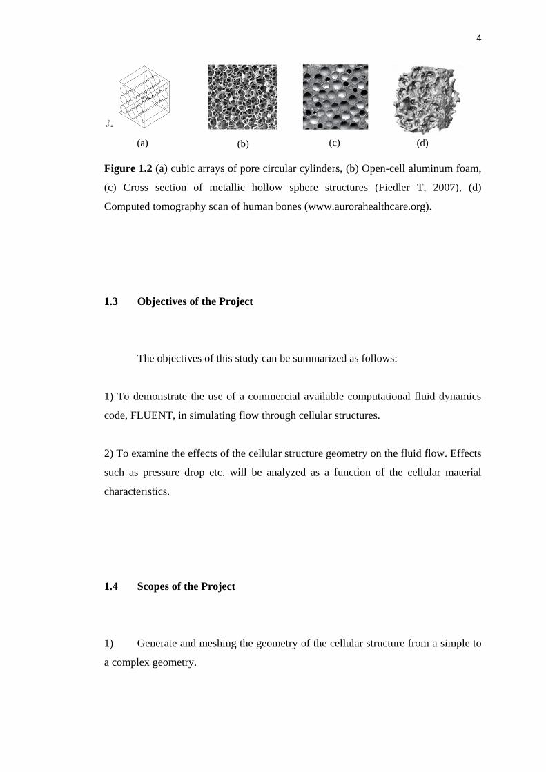
Many attempts have been carried out in order to simulate the fluid flow
through a cellular structure such as simplified model structures, porous hollow
sphere structures, open cell metal foam and human bones, respectively, are shown in
Figure 1.2. This study investigates the characteristics of a fluid (liquid or gas) flow
through a rigid, cellular structure. The use of a cellular structure in fluid-flow
applications requires entire understanding of the behavior of the fluid flowing
through the porous structure, in which the pressure gradient, velocity distribution
through the cellular structure and shear stress are significantly required. Hence, in
this present work the “Computational Fluid Dynamic” (CFD) analysis is used to
model the flow through a cellular structure; to this end, modeling a flow in a
rectangular channel, the pressure drop and the uniformity of the flow through a
cellular structure can be determined using this method. The main purpose of this
study is to apply the finite volume method for solving problems involving a fluid
flow through cellular structures by means of the FLUENT software. FLUENT is
used to model the flow of the fluid through cellular structure geometry which enables
to analyze the flow field properties.
inlet outlet 𝑥
𝑦
z
Cellular structure
4
Figure 1.2 (a) cubic arrays of pore circular cylinders, (b) Open-cell aluminum foam,
(c) Cross section of metallic hollow sphere structures (Fiedler T, 2007), (d)
Computed tomography scan of human bones (www.aurorahealthcare.org).
1.3 Objectives of the Project
The objectives of this study can be summarized as follows:
1) To demonstrate the use of a commercial available computational fluid dynamics
code, FLUENT, in simulating flow through cellular structures.
2) To examine the effects of the cellular structure geometry on the fluid flow. Effects
such as pressure drop etc. will be analyzed as a function of the cellular material
characteristics.
1.4 Scopes of the Project
1) Generate and meshing the geometry of the cellular structure from a simple to
a complex geometry.
(a) (b)
)
(c) (d)

5
2) To investigate the fluid flow behavior for different cellular structures with
different porosity by using the FLUENT software.
3) Validation of obtained result by comparing with earlier research.