investigation into building an openflow-enabled...
TRANSCRIPT

Investigation into Building anOpenFlow-enabled BNG
A reportsubmitted in fulfillment
of the requirements for the degreeof
Bachelor of Computing and Mathematical Sciences withHonours
atThe University of Waikato
by
Craig Osborne
Department of Computer ScienceHamilton, New Zealand
October 20, 2014
c© 2014 Craig Osborne
Abstract
In carrier-grade Internet Service Provider (ISP) networks the Broadband Net-work Gateway (BNG) is a specialised network server which sits at the core ofan ISP network. The responsibilities of the BNG include the facilitation andaggregation of active user sessions from the ISP’s access network, and provid-ing Internet Protocol (IP) connectivity through the ISP backbone network tothe Internet. In a typical ISP carrier network, the BNG is one of the mostexpensive appliances and carries a high degree of responsibility. Due to thecost, it is common for there be only a single centralised BNG, which presentsa singular point of failure (SPOF) for all ISP subscriber access to the Inter-net. This project aims to investigate whether the centralised BNG model isable to be redesigned using a new approach to computer networking calledSoftware Defined Networking (SDN). Using SDN and the OpenFlow protocolwill allow for the separation of the traffic forwarding logic of a switch fromthe data plane, enabling that logic to be moved into an application running insoftware. This results in a much more software oriented approach to networkdesign and the control and configuration of switches. This project aims toinvestigate the removal of singular dependence on the centralised BNG modelby distributing the functionality of a BNG among a network of commodityswitches. There is a strong focus on implementing support for a number ofimportant session establishment protocols and how these can be used to makenecessary dynamic traffic forwarding decisions, as well as the investigation ofa carrier-grade distributed software controller.

Acknowledgements
Firstly, I would like to thank my project supervisor Dr. Richard Nelson forhis support and guidance throughout the course of this project. Additionally,I would like to thank Brad Cowie and Christopher Lorier from the WANDgroup for their advice and valuable input into my project as it has progressed.I would also like to thank Scott Raynel, Chris Browning and the rest of theteam from Lightwire for their support and valuable insight from the onset ofmy project and throughout. Finally, I would like to thank Adam Coxhead forhis advice and input in structuring my project and associated deliverables.
Additionally, I would like to thank Shane Alcock and Brendon Jones fromthe WAND group for their proof-reading and editorial input in creating thisreport.

Contents
Abstract ii
Acknowledgements iii
1 Introduction 1
2 Background 42.1 Software Defined Networking and OpenFlow . . . . . . . . . 42.2 Broadband Network Gateway . . . . . . . . . . . . . . . . . 82.3 Implementation Tools . . . . . . . . . . . . . . . . . . . . . . 112.3.1 Open vSwitch . . . . . . . . . . . . . . . . . . . . . . . . . 112.3.2 Ryu . . . . . . . . . . . . . . . . . . . . . . . . . . . . . . 12
3 Investigation 133.1 Software Defined Networking and OpenFlow Technologies . . 133.1.1 High Availability . . . . . . . . . . . . . . . . . . . . . . . 133.1.2 Protocol Support . . . . . . . . . . . . . . . . . . . . . . . 173.2 Broadband Remote Access Server . . . . . . . . . . . . . . . 183.2.1 Current Dependency Reduction Strategies . . . . . . . . . 183.2.2 Software Defined Networking and OpenFlow Solutions . . 19
4 Implementation 234.1 Broadband Network Gateway Session Aggregation . . . . . . 234.1.1 Dynamic Host Configuration Protocol . . . . . . . . . . . 244.1.2 Virtual Local Area Network . . . . . . . . . . . . . . . . . 294.2 Dynamic Flow Creation . . . . . . . . . . . . . . . . . . . . . 324.3 Anonymous Unicast Host Detection . . . . . . . . . . . . . . 33
5 Evaluation and Discussion 385.1 Broadband Network Gateway Session Aggregation . . . . . . 38

Contents v
5.1.1 Dynamic Host Configuration Protocol . . . . . . . . . . . 385.1.2 Virtual Local Area Network . . . . . . . . . . . . . . . . . 405.2 Dynamic Flow Creation . . . . . . . . . . . . . . . . . . . . . 425.3 Project and Technology Limitations or Difficulties . . . . . . 435.3.1 802.1ad VLAN Support . . . . . . . . . . . . . . . . . . . 435.3.2 Controller Scalability . . . . . . . . . . . . . . . . . . . . . 465.3.3 Controller Distributivity . . . . . . . . . . . . . . . . . . . 475.3.4 API Documentation . . . . . . . . . . . . . . . . . . . . . 485.3.5 Bugs and Software Regression . . . . . . . . . . . . . . . . 49
6 Conclusions 516.1 Contributions Made . . . . . . . . . . . . . . . . . . . . . . . 516.2 Future Work . . . . . . . . . . . . . . . . . . . . . . . . . . . 516.2.1 Additional Protocol Support . . . . . . . . . . . . . . . . . 526.2.2 Flow Management and Operational Robustness . . . . . . 526.2.3 Additional Authentication, Authorisation and Accounting
Support . . . . . . . . . . . . . . . . . . . . . . . . . . . . 546.2.4 Complex Network Topologies . . . . . . . . . . . . . . . . 546.2.5 Real World Testing and Evaluation . . . . . . . . . . . . . 556.3 Conclusions . . . . . . . . . . . . . . . . . . . . . . . . . . . 55
References 57

List of Figures
2.1 OpenFlow 1.3 Protocol and Switch Visualisation . . . . . . . . . . 62.2 BNG operation in IP-enabled regional ISP network . . . . . . . . . 10
3.1 Apache Zookeeper operation with multiple OpenFlow controllers . 163.2 PPPoE session creation with split architecture BNG model . . . . 21
4.1 Controlled DHCP session establishment process . . . . . . . . . . . 274.2 Example of basic VLAN port configurations . . . . . . . . . . . . . 304.3 Anonymous unicast flooded ARP request example . . . . . . . . . 354.4 Anonymous unicast ARP response example . . . . . . . . . . . . . 36
5.1 802.1ad operation in an ISP network . . . . . . . . . . . . . . . . . 44
List of Tables
2.1 Example flow table entry . . . . . . . . . . . . . . . . . . . . . . . 7
4.1 Packet characteristics for matching DHCP control flow entry . . . 264.2 Example flow entry pair for subscriber WAN access . . . . . . . . . 28
5.1 Basic 802.1ad VLAN-stacked ARP packet . . . . . . . . . . . . . . 455.2 Distributed vs. redundant controller comparison . . . . . . . . . . 48

List of Acronyms
AAA Authentication, Authorisation and Accounting
ADSL Asymmetric Digital Subscriber Line
API Application Programming Interface
ARP Address Resolution Protocol
ASP Application Service Provider
ATM Asynchronous Transfer Mode
BNG Broadband Network Gateway
BRAS Broadband Remote Access Server
CFI Canonical Format Indicator
CPE Customer Premises Equipment
CVID Customer VLAN Identifier
DEI Drop Eligible Indicator
DHCP Dynamic Host Control Protocol
DSL Digital Subscriber Line
DSLAM Digital Subscriber Line Access Multiplexer
EAS Ethernet Aggregation Switch
HVID Handover VLAN Identifier
IP Internet Protocol
IPoE Internet Protocol over Ethernet
IPv4 Internet Protocol Version 4
IPv6 Internet Protocol Version 6

List of Tables ix
ISP Internet Service Provider
IWF Interworking Function
L2TP Layer 2 Tunnelling Protocol
L2TS Layer 2 Tunnelling Server
LAC L2TP Access Concentrator
LFC Local Fibre Carrier
LNS L2TP Network Server
MAC Media Access Control
MPLS Multiprotocol Label Switching
NAS Network Access Server
NOS Network Operating System
NSP Network Service Provider
OAM Operations, Administration, Management
ONF Open Networking Foundation
ONT Optical Network Terminator
ONU Optical Network Unit
OVS Open vSwitch
PPP Point-to-Point Protocol
PPPoA Point-to-Point Protocol over ATM
PPPoE Point-to-Point Protocol over Ethernet
QOS Quality of Service
RAS Remote Access Server
ROFL Revised OpenFlow Library
RSP Retail Service Provider
SDN Software Defined Networking
SLIP Serial Line Internet Protocol

List of Tables x
SPOF Single Point of Failure
SVID Service VLAN Identifier
TCI Tag Control Information
UDP User Datagram Protocol
UFB Ultra Fast Broadband
VLAN Virtual Local Area Network
WAN Wide Area Network
WISP Wireless Internet Service Provider

Chapter 1
Introduction
With the introduction of many new technologies and approaches to computernetworking in recent years, there now exist better or smarter ways to imple-ment existing network models and architectures. Many researchers are en-gaging with these new technologies in an attempt to discover ways in whichcommon network architectures may be improved in order to better cater tothe requirements of that network model. One such new technology, Software-defined networking (SDN) [7], is an emerging approach to computer networkingwhich allows network administrators to decouple the control plane (the compo-nent responsible for a device’s decision making behaviour) away from expensivespecialised networking hardware. This enables the abstraction of control logicfor that network hardware to a series of software controllers running remotelyon cheaper commodity consumer hardware. The OpenFlow protocol [18] is onesuch SDN communication protocol which allows this relationship to be defined,allowing communication between these two newly distinct entities - the dataplane (the component responsible for a device’s traffic forwarding capabilities)and the control plane. This approach allows administrators to define theirown specific traffic forwarding behaviours in the decoupled software controlplane, facilitating the management of entire networks remotely with a series ofcustom software-defined rules that can extend the capabilities of typical com-modity hardware. Such rules or behaviours are installed in network hardwareas traffic flows (modifications to the device’s packet forwarding table), whichare a series of executable actions that are taken when incoming packets matchspecific series of pre-defined characteristics.
In existing Internet Service Provider (ISP) networks, one network model that

Chapter 1 Introduction 2
may be improved upon with the advent of SDN is the Broadband NetworkGateway (BNG) architecture, also known as the Broadband Remote AccessServer (BRAS) architecture. In smaller ISP networks where costs may be re-strictive, a centralised BNG model represents a single point of failure (SPOF)for the entire ISP subscriber base. If the BNG in this architecture were to fail,all active ISP subscribers would lose the ability to connect through the ISP’saccess network to the Internet or another service provider, as all subscribersessions must traverse the BNG. If the structural principle of non-singulardependence on any critical appliance can be applied in some manner to thisexisting BNG architecture using SDN, it may be possible to improve the ISPcarrier network’s operational capabilities. By decoupling any intermediaryswitch’s control planes away from their switching silicon and instead abstract-ing them to multiple SDN software controllers, it may be possible to increasethe network efficiency and robustness of the ISP carrier network. This can beachieved by decreasing the dependency on specific individual appliances andspreading the existing BNG functionality among multiple devices. The abilityfor a SDN-capable network to distribute any of these software-defined trafficforwarding rules across the network itself may help structure the proposed ar-chitecture into a distributed non-centralised model for which dependence onlyexists on controllers for those packets which do not already match any existingflows. Investigating the plausibility of improving upon the existing ISP cen-tralised BNG architecture in this manner was the primary motivation for theconception of this project.
This investigation considers and evaluates the replacement of the existing BNGarchitecture with a series of one-to-many software controllers running the RyuSDN development framework [10], which implement the same BNG function-ality by distributing the traffic forwarding logic across a series of OpenFlow-enabled layer 2 hardware switches, instead of relying on logical dependenceon a single authoritative BNG. To evaluate the feasibility of this approach, aprototype implementation was constructed with the use of Ryu, and labora-tory tests were conducted using a series of virtualised hosts interconnectingthrough Open vSwitch (OVS) [31].
This report first introduces the background concepts and core workings of SDNand BNG operation in Chapter 2. In Chapter 3, some of the requirements for

Chapter 1 Introduction 3
a replacement ISP BNG system are outlined and related works are discussed.Chapter 4 presents ways in which the outlined requirements can be addressedwith an OpenFlow inspired system design using constructed OpenFlow con-trollers and flow mechanisms. Finally, Chapter 5 contains the evaluation anddiscussion of presented approaches, including deployment scenarios and real-world limitations. Project conclusions, contributions and discussion of futurework are provided in Chapter 6.

Chapter 2
Background
There are many concepts and protocols integral to the development of anysoftware controller-based solution for this project, primarily revolving aroundthe SDN and OpenFlow concepts and the BNG’s current purpose and func-tion. Relevant SDN and OpenFlow concepts which make this project possibleform the basis of Section 2.1. Section 2.2 introduces the BNG, its backgroundand general behaviours, and the rationale behind improving upon its existingarchitecture. Lastly, Section 2.3 briefly describes the tools which will be usedto build and implement this project.
2.1 Software Defined Networking and OpenFlowTraditional network switches are comprised of two distinct planes; the dataplane which is responsible for the forwarding of packets through the switch,and the control plane which is responsible for making decisions on how toforward those packets. Traditionally, these two planes exist within the samephysical switch and are tightly coupled together. SDN allows these two en-tities to be abstracted away from one another, separating a network switch’scontrol plane away from its data plane. This allows for the control plane tobe moved to a software application running remotely. This concept allowsfor a control plane to enjoy a higher degree of abstraction than is the normin network switches, i.e. software can be written to dynamically determinethe configuration of any switches being controlled, as opposed to the stricthierarchy of behaviours that a switch’s control plane would otherwise use togovern data plane traffic forwarding. This remote control plane entity govern-

Chapter 2 Background 5
ing traffic forwarding behaviours is aptly named the controller, although itis also known as a Network Operating System (NOS). As a result of us-ing a controller, network administrators gain unprecedented programmability,automation, behavioural visibility, and control over their switch’s operation,enabling them to design and build highly scalable, flexible networks that read-ily adapt to changing needs. SDN supports these characteristics by openingaccess to the control plane where previously it had been considered a blackbox entity. Subsequently a SDN-capable network switch with an abstractedcontrol plane would no longer be bound to the same inherent limitations tra-ditional switches are. This can permit the extension of switch functionalitywithout the need to modify the existing switch hardware or firmware. Fur-thermore, SDN enables researchers and administrators to easily experimentwith new network protocols and configurations on production networks con-currently alongside existing systems, without any negative impact. This canallow network operators to introduce higher degrees of network flexibility, ef-ficiency and provisioning agility into their networks, while keeping operatingexpenses and capital expenditure down.
The relative infancy of SDN means that the standardisation of its related pro-tocols is still taking place, as contributors seek to interface with other olderwell-defined networking standards and protocols. This inevitably leaves roomfor students, researchers and administrators to address the development of newor compatible implementations of existing networking models and protocols,presenting them with the opportunity to improve the way existing networkmodels operate [3].
OpenFlow is widely considered one of the first SDN standards and outlinesthe communications protocol which allows separated or decoupled control anddata plane entities to communicate with one another. OpenFlow also providesa switch specification which allows the configuration of a switch via the sameprotocol. Originally it was designed as a tool by which researchers were able torun experimental protocols on existing networks by way of separating exper-imental traffic from production traffic [18]. However, as discussed in [8], [11]and [19], the advantages of SDN solutions using OpenFlow introduces viableuse cases outside the research space. The primary idea behind the OpenFlowprotocol is to provide an open Application Programming Interface (API) for

Chapter 2 Background 6
the configuration of and interaction with the packet-forwarding hardware of aswitch, regardless of the switch’s vendor or underlying hardware. It allows fora controller to be logically centralised in a network, providing a basis on whichnew behavioural approaches to existing network architectures or models canbe undertaken.
Figure 2.1 shows a basic visual representation of the relationship between anOpenFlow controller and an OpenFlow-enabled switch. Here the switch con-sists of two primary parts: a secure channel and a series of flow tables. The
Figure 2.1: OpenFlow 1.3 Protocol and Switch Visualisation

Chapter 2 Background 7
controller manages the switch over the secure channel using the OpenFlow pro-tocol and each flow table performs packet lookup, matching and forwarding[25]. Each flow table is used in this context to determine a packet’s destina-tion and decide how the switch subsequently forwards it on. Each flow tableconsists of a series of flow entries, which each consist of a series of differentcomponents. “Flow” in this context is defined as a series of packets that matcha particular rule. Using OpenFlow, any packet that does not match any of thecurrently established flow rules held within the switch’s flow table will be sentto the controller, which in turn decides how to handle the packet. The Open-Flow protocol allows a controller to insert, modify and remove these flow tableentries dynamically allowing for the rapid and flexible reconfiguration of theswitches. The first element in a flow table is “match fields”, which are thefields of a packet header or associated meta data which determines whether apacket matches a specific flow or not. A series of different match fields maybe used in conjunction with one another to define a directive or a rule for apacket to follow. An example of a rule based on match fields would be one thatassigns packets to flows based on the data stored in either the source or desti-nation Media Access Control (MAC) address fields in the Ethernet header. Insuch a case, any packets containing the same source and destination address asdetermined by the rule would belong to the same common flow and would behandled according to the instructions in the flow table. An example of whatthat flow entry might look like is shown in Table 2.1.
Match Fields Priority Counters Instructions Timeouts Cookiedl src=00:11:22:33:44:55, priority= duration=803s, action= duration= cookie=dl dst=aa:bb:cc:dd:ee:ff 100 n packets=6, output:5 3600s -687779960
n bytes=688
Table 2.1: Example flow table entry
The next element in a flow table entry is the “priority” field, which determinesthe precedence of the flow entry, allowing flow rules with a higher priority tobe chosen over those with a lesser priority. Next is the “counters” field, whichupdates the internal packet counters and maintains an awareness of how manypackets are being forwarded through each specific flow. The “instructions”field follows afterwards, which determines what actions should occur upon re-ceipt of packets matching the specific rule criteria. In the earlier example,the instructions field could be configured to forward packets through a specific

Chapter 2 Background 8
port or interface on the switch if the previously determined matching criteria(source/destination MAC addresses) were met. In Table 2.1, the instructionfield determines that any packets matching these criteria are forwarded out ofport 5 of the switch. Lastly, the remaining fields in the flow table include the“timeouts” field, which determines how long a flow can exist for or remain idlein the flow table before being expired by the switch, and the “cookie” field,which is used in administrative tasks performed by the switch.
Since the OpenFlow switch specification version 1.0 released in 2009 [22], therehave been four iterations of the OpenFlow standard [23, 24, 25, 27], with thenext version (1.5) expected in late 2014 [4, 28]. OpenFlow switch specifica-tion 1.0 was widely considered the first official specification of the OpenFlowstandard, and represented the first standardisation for which an OpenFlowswitch could be constructed from. This specification remains the most com-mon and widely supported version of OpenFlow. Each subsequent versionof OpenFlow introduced additional features into the standard which wouldprove integral to the feasibility of this project. OpenFlow 1.1 introduced sup-port for multiple flow tables that allowed the introduction of more complexforwarding actions inside a switch, and Virtual Local Area Network (VLAN)tag support for handling packets with a hierarchy of multiple VLAN tags [9].OpenFlow 1.2 introduced more extensible matching criteria for packet parsingand multiple-controller functionality for maintaining simultaneous connectionsbetween multiple OpenFlow controllers using roles. OpenFlow 1.3 includes themost significant changes and improvements to the specification since OpenFlow1.0, adding flexible table-miss support for better handling of packets which donot already match existing flows and Quality of Service (QoS) capabilitiesthrough per-flow meters. OpenFlow version 1.3 has been used for the con-trollers created for this project. Newer versions of OpenFlow exist, but theseare either not widely supported yet or are still being written.
2.2 Broadband Network GatewayThe ISP BNG model has seen many iterative changes since originally describ-ing a Remote Access Server (RAS) for dial-up Internet access over the publicswitched telephone network. The RAS was an access server that acted as a

Chapter 2 Background 9
network gatekeeper for an ISP and was responsible for facilitating networkaccess for incoming subscriber sessions off an access network using either theSerial Line Internet Protocol (SLIP) or Point-to-Point Protocol (PPP). AsDigital Subscriber Line (DSL) broadband was gradually introduced, the RASmodel was modified to suit the needs of the newer Asynchronous Transfer Mode(ATM) based Asymmetric DSL (ADSL) technology, in what would become theBRAS [1]. The BRAS filled fundamentally the same role as network gatekeeperand session aggregator. The BRAS served for several years before being mod-ified to accommodate newer non-ATM technologies and as Internet Protocol(IP) QoS capabilities became necessary [39, 40]. As broadband technologiescontinued to evolve, Ethernet-based DSL aggregation became prevalent andthe BNG was formally defined [41]. The BNG encompassed the function-ality of the BRAS, but as the BNG did not form a required component ofnew Ethernet-based architectures, the use of the BNG title was required toclarify between these two different appliances. The new Ethernet-based net-works often delegated subscriber session establishment to alternate non-PPPprotocols, such as IP-over-Ethernet (IPoE) (including other protocols such asDynamic Host Configuration Protocol (DHCP) and VLAN). As such, mod-ern day BRASs and BNGs now require a greater range of supported protocolsand session management capabilities to better serve a wide range of differentnetwork access mediums. These appliances facilitate the capability to supportaccess-media-agnostic IP-based access networks, allowing for the extensiblemigration from ATM-based DSL to other technologies [12].
The BNG typically functions at the core of an ISP network infrastructure andis responsible for aggregating incoming subscriber sessions coming from an ac-cess network (i.e. ADSL, Ultra Fast Broadband (UFB) fibre or 802.11-basedwireless) and enforcing subscriber-associated policy. The subscriber sessionsare then forwarded through the ISP IP core by the BNG to an edge routeror another termination point (i.e. a Layer 2 Tunnel Switch (L2TS), NetworkService Provider (NSP) or Application Service Provider (ASP)). Figure 2.2depicts a basic BNG architecture and shows the relationship that exists be-tween the BNG and a number of other components in an ISP network. Inthis example, which has been simplified to show a single subscriber and accessmedium, the BNG receives the active subscriber session from an ADSL-basedaccess network. The access network consists of a Customer Premise Equip-

Chapter 2 Background 10
Figure 2.2: BNG operation in IP-enabled regional ISP network
ment (CPE) at the edge of the customer network, which allows the subscribertraffic to access the copper telephone lines through a modem. The DigitalSubscriber Line Access Multiplexer (DSLAM) aggregates the analog signalscarried across the individual subscriber DSL circuits. The analog data is sub-sequently transported in ATM packets to the ISP network and into the BNGwhere it is facilitated for authorisation and authentication accordingly. TheCPE authenticates with the ISP using PPP over ATM (PPPoA)1 to encapsu-late its associated subscriber session establishment information and the BNGwill either terminate each PPPoA session itself or facilitate doing so througha Network Access Server (NAS) or one of the other connected Authentica-tion, Authorisation and Accounting (AAA) servers. Depending on whetherthe PPPoA session credentials were correct and what policy may exist for thissubscriber, the BNG either then forwards subsequent subscriber traffic throughthe ISP network to the appropriate destination or rejects the authenticationattempt outright. Appropriate destinations for subsequent subscriber packetsto be forwarded to include typical endpoints, such as a Layer 3 IP router forexternal network access (e.g. the Internet), a L2TS (to handle additional PPPencapsulation) or another Layer 2 switch.
There are many different ISP architectures which may involve a BNG appli-ance. One issue with the architectural model presented in Figure 2.2 is that
1Applicable to this example only. CPEs may authenticate using a number of protocols,such as PPP over Ethernet (PPPoE) or Internet Protocol over Ethernet (IPoE)

Chapter 2 Background 11
the BNG is a SPOF for subscriber access to the Internet or other serviceproviders. Although many ISP network configurations contain more than asingle BNG, this single centralised BNG configuration is still common, espe-cially among smaller ISPs. Even though most BNG hardware itself is classifiedas a carrier-grade appliance (which carries 99.999% availability expectations)this dependency is not just problematic from a fault or failure point of view.Full BNG appliances regularly extends beyond simply the price of the physi-cal hardware (i.e., support, licensing, and add-on card costs) so scaling to therequirements of the network by acquiring multiple or redundant BNGs canresult in substantial costs to the ISP itself.
This project looks at addressing and removing the dependency on a centralisedBNG appliance in modern-day ISP network architectures by moving away froma centralised model to a distributed, decentralised one using SDN concepts andtechnologies. This will offer an improved architecture not just to those net-work configurations where a sole BNG facilitates all subscriber aggregation,but also to other network configurations where distributing and bringing theBNG functionality closer to the subscribers themselves may have performanceadvantages. Using SDN and OpenFlow, it is hoped this project introducesadvantages such as increases to speed, versatility and robustness of the ISPnetwork model, as well as subsequent reduction of costs associated with theconstruction and ongoing support of that network.
2.3 Implementation Tools
2.3.1 Open vSwitch
OVS is an open source multilayer virtual switch. It has been designed as both aswitching stack for hardware virtualisation and a production-ready multilayerswitch, allowing for both the creation of complete virtual Layer 2 networkson a single host and control stack functionality for actual hardware switches.OVS has native support for OpenFlow versions 1.0-1.3, and since the releaseof OVS version 2.3.0 also mostly supports later OpenFlow versions (1.4, 1.5).Due to the obvious limitations of building and emulating a sufficiently sizedreal-world ISP network configuration for this project, OVS is an excellent tool

Chapter 2 Background 12
to realistically design and simulate OpenFlow-enabled network architectures.
2.3.2 Ryu
There are many open source OpenFlow controllers currently available, includ-ing Beacon [5], Floodlight [6], Trema [44], OpenDaylight [29] and Ryu [10].Among these different frameworks, only Ryu includes support for all of theOpenFlow versions discussed in Section 2.1, whereas the other noted frame-works mostly only support OpenFlow version 1.0 in an official capacity. Ryu isa Python-based framework and is highly suitable for rapid prototyping. Ryuoffers a component-based SDN framework which provides software componentsbacked by a well-defined API. Ryu makes it easy for developers to create andbuild new network management and control applications, and supports vari-ous network device management protocols. In this project Ryu has been usedto design, build and implement various OpenFlow controllers to achieve theoutlined goals of the projects.

Chapter 3
Investigation
3.1 Software Defined Networking and OpenFlowTechnologies
This section is focused on investigating concepts and discussing research in thearea of SDN and the OpenFlow protocol which may influence the direction ofthe project. It will address some of the concepts and research being carriedout in the area of high availability OpenFlow controllers, as well as work in-vestigating the necessary supported network communication protocols. Thepractical realisations, implementation details and limitations of these areaswill also be explored in the context of achieving the project aims.
3.1.1 High Availability
One of the primary motivations in the context of reducing dependency on spe-cific system components is high availability of the system itself, i.e. operationalavailability of the system that is able to be maintained continuously for longperiods of time. This is often achieved with failover mechanisms and systemredundancy, which allow the system to continue to function even if some oper-ational components of that system were to fail. In order to sufficiently reducethe singular dependence on a centralised BNG in existing ISP architectures,any developed distributed BNG architecture must maintain this property ofhigh availability. Given that one of the primary aims of this project is to re-duce singular dependence on the BNG appliance, any architectural model thatis designed to replace it should not suffer from the same singular dependence

Chapter 3 Investigation 14
vulnerability. Some of the mechanisms investigated to introduce high avail-ability into this project are discussed below.
Distributed OpenFlow Controllers
OpenFlow controllers capable of operating concurrently in a distributed fashionare an important step towards achieving high availability in this project. Rely-ing on a single OpenFlow controller fails to introduce a reduction in dependencefrom a single BNG, and therefore the introduction of additional controllerswould be advisable. Additionally, the Ryu OpenFlow controller frameworkdoes not support multi-threading and will subsequently fail to scale success-fully to cater for the large throughput values that a BNG would encounter[33]. Therefore, one solution to this problem would be to introduce multipleOpenFlow controllers which are able to distribute the governance and load ofthe network amongst themselves equally, removing both the singular depen-dency and throughput scale issues. This contributes towards high availabilityby distributing the total network load across multiple points-of-presence mean-ing that no single controller is expected to facilitate the establishment of allrequired subscriber flows. A controller framework structured this way couldalso continue to function in the absence of all participating controllers, intro-ducing redundancy to the architecture. Furthermore, OpenFlow controllersimplemented in this fashion gain the additional advantage of being able to bedeployed closer to their target switches, introducing speed advantages to thenetwork by virtue of reducing the latency of the behavioural control and trafficforwarding interactions between the controller and switches.
One of the major pitfalls of running a distributed series of OpenFlow controllersis the requirement for controllers to freely exchange state information aboutthe network switches they govern. While there have been a number of stud-ies conducted on distributed controller frameworks which appear to achievethis property [14, 35, 43], no mechanism yet exists for this functionality tobe achieved using Ryu. Given that an investigation into achieving OpenFlowcontroller distributivity using Ryu is a research question in its own right andis too large in scope for this context of this project, the decision to pursuea distributed controller framework for this project was therefore investigatedbut not implemented.

Chapter 3 Investigation 15
Redundant OpenFlow Controllers
As noted in Section 2.1, the OpenFlow switch specification from version 1.2onwards describes mechanisms for OpenFlow controllers to exchange role in-formation between themselves. The roles the controller may take vary between‘equal’, ‘master’, and ‘slave’. The ‘equal’ role (OFPCR ROLE EQUAL) is thedefault role that the controller will take unless otherwise specified. This givesthe controller full access to a switch and its associated asynchronous messagesused for governance, as well as full flow table read/write capabilities. Thedisadvantage of the ‘equal’ role is that multiple controllers may share thisrole equally and contest governing a given switch individually instead of col-lectively. The switch does not facilitate any arbitration or resource sharingbetween the controllers [26], so it is wasteful to have multiple controllers vyingfor control of the same switch without first synchronising state informationto establish between those controllers any prior behavioural traffic forwardingdecisions made on the switch’s behalf.
The remaining ‘master’ and ‘slave’ roles (OFPCR ROLE MASTER and OF-PCR ROLE SLAVE respectively) allow the controllers to be configured in aredundant relationship. The ‘master’ controller role is similar to the ‘equal’controller role, except in any controller configuration it is expected there willbe only a single master controller. This master controller retains the fullread/write capabilities for each governed switch’s flow table and other controlmessaging mechanisms. Any remaining controllers in this master/slave config-uration are marked as slaves and therefore are only permitted read-only accessto the switch. Slave controllers are denied the ability to execute any controller-to-switch commands. Additionally, the roles can freely be exchanged betweencontrollers in the configuration. If a slave controller were to decidedly rise tothe role of master, the intermediary switches immediately notify and forciblychange the existing master controller to the ’slave’ role. A role request mech-anism (OFPT ROLE REQUEST) is used to facilitate this change.
The role request mechanism enables administrators to easily tie active con-troller states to external watchdog applications as a way of monitoring thehealth of the controllers in a common configuration. Such a mechanism allows

Chapter 3 Investigation 16
Figure 3.1: Apache Zookeeper operation with multiple OpenFlow controllers
the election of a new master controller in the case that the existing master con-troller fails or an event determining that the controller roles should change oc-curs. One example of an open source application capable of achieving this withthe Ryu controller framework is Apache Zookeeper [38]. Apache Zookeeper canbe used to achieve high availability with a series of OpenFlow controllers bymaintaining an awareness of the current status or role of any controllers in theconfiguration. If the master controller in the configuration were to match apredetermined failure condition or stop responding, Zookeeper is able to triggeran event and notify the remaining slave controllers, subsequently causing a newmaster controller election process among the slave controllers. A basic exam-ple of this relationship is visually represented in Figure 3.1. Zookeeper helpsensure high availability of the controllers by facilitating an elegant failovermechanism. However, Apache Zookeeper does not achieve high availabilityon its own. Administrative attention is still required to remedy any ‘failed’

Chapter 3 Investigation 17
controllers. Fortunately, Zookeeper can likely lend itself to a comprehensivestateful monitoring system by notifying administrators of changes to the con-troller configuration. The disadvantage of this approach however is that allflow creation still takes place on a single controller at a time.
3.1.2 Protocol Support
An important consideration to achieve a viable BNG replacement architecturefor this project was determining which required communications protocols weresupported and able to be handled or parsed by the Ryu OpenFlow controllerframework. As evidenced by [40] and [41], a standardised BNG is required tounderstand and handle a substantial number of different protocols with specificconfiguration requirements in order to both support end users on an access net-work and connectivity to upstream NSPs or ASPs1. Any developed OpenFlowcontroller needs to facilitate the handling of these protocols in an agnosticmanner and have the ability to forward any related packets to the correctdestinations, for instance from a Layer 2 Tunnelling Protocol (L2TP) AccessConcentrator (LAC) through to an L2TP Network Server (LNS) for L2TPtraffic, or a DHCP Server for DHCP IP lease establishment traffic. Therefore,the controller must be able to read, analyse, and categorise different packetsbased on values extracted from various Internet Protocol Version 4 (IPv4) andInternet Protocol version 6 (IPv6) packets, Ethernet frame header fields, orencapsulated packet data payloads.
Ryu contains a moderately sized API and packet library with support for anumber of common protocols [32]. Despite the absence of existing API calls forseveral necessary protocols such as L2TP and PPP over Ethernet (PPPoE),the full contents of layer 3 IP packets are exposed to the controller. Thisgives developers the ability to extract IP layer headers and payloads individ-ually from each packet the controller is forwarded. Subsequently, developersare able to write protocol handling functionality into their controller, or alter-
1The exception to this are those protocols which do not get encapsulated inside Ethernetframes and do not present as Ethernet to a layer 2 Ethernet switch, such as ATM-basedDSL networks which still use ATM upstream of the DSLAM. In order to accommodateATM-based DSL networks, the assumption has been made that an interworking function(IWF) will be present in modern day DSL-based access networks in order to allow theDSLAM to present aggregated subscriber sessions encapsulated inside Ethernet frames.

Chapter 3 Investigation 18
natively use a third-party packet library such as libpcap [15] with scapy [2].While the ability to expose packet data and process it with custom-writtenprotocol handlers is a useful capability, it would have been preferential if theRyu framework supported a wider range of protocols by default. One likelyreason for the lack of supported protocols for carrier-grade ISP networkingusing Ryu is the lack of support for these protocols in OpenFlow itself.
3.2 Broadband Remote Access ServerThis section focuses on investigating concepts and discussing existing works onthe existing BNG architecture which may influence the direction the projectultimately takes. Existing practical realisations and implementations will bediscussed as well as any limitations of these approaches with respect to thisproject.
3.2.1 Current Dependency Reduction Strategies
Carrier network architectures employ a number of approaches to distribute thenecessary functionality of the BNG appliance out to other devices in order toreduce any inherent SPOF vulnerabilities present in the basic model depictedin Figure 2.2. These approaches do not replace the BNG appliance itself butrather simply distribute its functionality among multiple appliances. Theseapproaches typically employ specifically designed carrier network architecturesand are commonly seen in larger ISPs. Some of these architectures use multipleBNG appliances distributed among a series of variably-sized regional networkssuch that a SPOF may still remain for a given access network but may onlyaffect a smaller geographically-locked subset of subscribers. Other approachescluster multiple BNG appliances together to ensure high availability of thesession aggregation capabilities by failing over to secondary or tertiary appli-ances in the event of a fault or failure [36]. These approaches help removethe SPOF vulnerability associated with using a single centralised BNG appli-ance, but carry a high cost. The cost can be restrictive for smaller ISPs andcan present a barrier to entry in a competitive market place, therefore lendingmerit to investigating alternative BNG approaches. Those approaches whichlook to resolve this dependency but do not rely on dedicated BNG appliances
Chapter 3 Investigation 19
are few in number, but those which have been documented aim to distributethe embedded functionality of the BNG among other network appliances toremove specific dependencies.
One such approach to distributing functionality typically handled by the BNGappliance was presented in [17]. The presenter described a Wireless ISP(WISP) where a series of PPPoE termination servers or NASs were load bal-anced behind the primary router at the access network edge. A load balancedsolution between multiple PPPoE termination points allowed users connectingand authenticating through this wireless access network to be equally dis-tributed among a series of servers. Such an approach not only ensured highavailability for the authentication service itself through the use of multipleend points, but also enabled a solution that scales to the requirements of thenetwork. Using such an approach would easily facilitate the addition of moreNASs, enabling the network administrators to respond to subscriber growtheasily with additional hardware. The physical topology of such an approachcould additionally be designed in order to provide authentication server ser-vices much closer to the subscriber base than modern architectures do. Thespeed at which session negotiation is facilitated could therefore be improved.Additionally, this approach could be improved by distributing the function ofthe access network edge router among multiple edge routers such that anySPOF is not simply moved closer to the customer by having all subscribersessions route through a single common appliance.
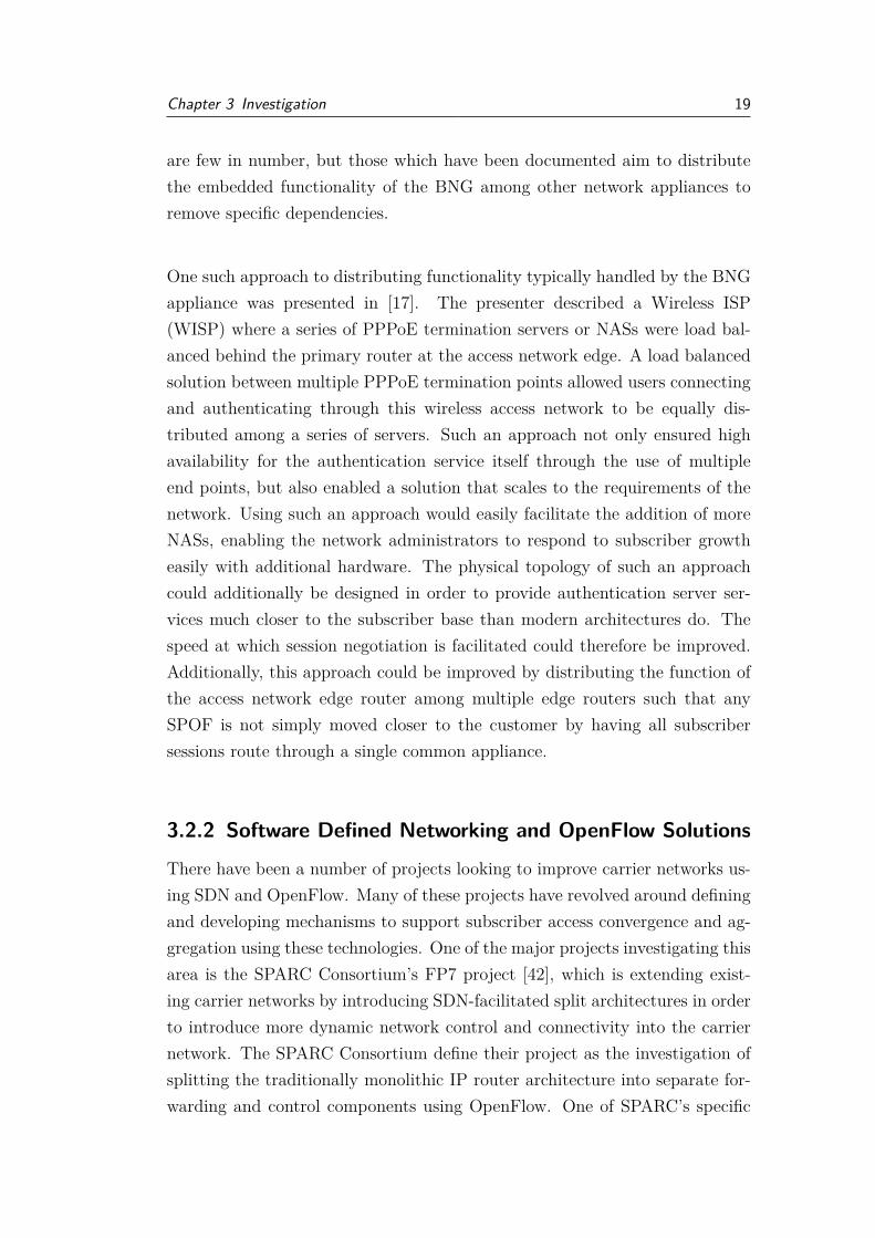
3.2.2 Software Defined Networking and OpenFlow Solutions
There have been a number of projects looking to improve carrier networks us-ing SDN and OpenFlow. Many of these projects have revolved around definingand developing mechanisms to support subscriber access convergence and ag-gregation using these technologies. One of the major projects investigating thisarea is the SPARC Consortium’s FP7 project [42], which is extending exist-ing carrier networks by introducing SDN-facilitated split architectures in orderto introduce more dynamic network control and connectivity into the carriernetwork. The SPARC Consortium define their project as the investigation ofsplitting the traditionally monolithic IP router architecture into separate for-warding and control components using OpenFlow. One of SPARC’s specific

Chapter 3 Investigation 20
target areas of research is improving the OpenFlow protocol for use in car-rier networks and researching how it may be deployed to achieve IP routerfunctionality similar to that of a BNG appliance. In some of their resultingpublications [13, 34] they suggest that the OpenFlow version 1.0 standard lacksin support for carrier grade network operation in areas such as supported com-munications protocols, inter-domain capabilities, and failure recovery. Theirinvestigation into different facets of redesigning the carrier network architec-ture using OpenFlow have resulted a number of relevant publications, some ofwhich are discussed below.
In [13], a SDN use case involving distributed BNG functionality is presented asa realised component of a carrier network split architecture. The use case is anOpenFlow-enabled carrier network and investigates how the former BNG’s rolein terminating PPPoE traffic is able to take place without a dedicated BNGappliance. The authors theorise that the actual termination of any PPPoEsessions will need to be abstracted to a separate NAS architecture (termed‘PPPoE application’), which connects to an OpenFlow controller. The con-troller is used to create and manage any initial flows between the PPPoE endpoints and intermediary network devices, as well as interfacing with the NASfor PPPoE control and access concentration. The flow creation process willneed to create flow table entries in intermediary devices that allow the PP-PoE application to receive both PPPoE discovery packets and PPP sessionpackets. The forwarding of those packets will be able to be facilitated by thoseOpenFlow-enabled intermediary devices based on these flow table entries. Thismodel however has only been outlined as an initial design, with the authorsconceding that any processing performed by the PPPoE application will re-quire extensions to the current OpenFlow protocol. However, this particulardistributed BNG model would have the disadvantage of being very slow atforwarding PPP-based traffic if implemented. The PPPoE application in thismodel is described as interfacing directly with the controller, rather than withthe common layer 2 network, which is also known as the ‘OpenFlow fast path’.This would mean that any PPPoE/PPP traffic required to reach the PPPoEapplication would have to be forwarded directly through the controller, ratherthan through the common network. This would substantially contribute to-wards a high load on the controller itself and in a production network wouldnot scale to a great number of users. A visual representation of this model is

Chapter 3 Investigation 21
depicted in Figure 3.2.
An additional paper that investigates an OpenFlow based BNG architectureis presented in [45]. It presents a prototype OpenFlow BNG and, similarlyto other papers discussed above, investigates an OpenFlow-based architecturecapable of terminating the PPPoE protocol. In this paper, the developedOpenFlow implementation was extended to include the Revised OpenFlowLibrary (ROFL) as a series of vendor extensions to accommodate PPPoE sup-port. Using ROFL enabled the authors to support the encapsulation/decap-sulation of PPPoE and PPP on the data plane, as these protocols are notyet defined in the OpenFlow standard. The outlined approach for handlingthese network protocols showed similarities to the design described in [13],whereby the PPPoE discovery frames (identified by a unique EtherType valueof ‘0x8863’) are sent to the OpenFlow controller for session establishment.PPP session frames (identified by a unique EtherType value of ‘0x8864’) aresubsequently handled solely on the data plane. The authors also outlined that
Figure 3.2: PPPoE session creation with split architecture BNG model

Chapter 3 Investigation 22
an important consideration for a model in which PPPoE is supported by anOpenFlow-enabled network is the ability to track the present states of thosePPPoE sessions which are currently active. They stipulated that althoughinitial designs handled session state in the controller, the use of virtual portswhich encapsulate session state was under consideration as a more efficientalternative. This paper shows that if OpenFlow-based technologies are to bepresented as a viable approach for improving upon existing carrier networkmodels and architectures, the OpenFlow standard must include more supportfor typical carrier network protocols. Although it is promising that some func-tionality for this family of protocols is obtainable through the use of vendorextensions, it is worth noting that vendor extensions are typically bound tovendor specific hardware and therefore make widespread adoption in carriernetworks difficult. Fortunately, a precedent has been set by the OpenFlowdevelopment team. Multiprotocol Label Switching (MPLS) protocol supportfor OpenFlow was in strong demand and began as a third-party documentedextension to the OpenFlow 1.0 standard. MPLS later became one of the firstnew protocols to be supported in the OpenFlow 1.1 standard, so it is likelythat there will be more protocol support as the standard continues to mature.

Chapter 4
Implementation
4.1 Broadband Network Gateway SessionAggregation
As mentioned in Section 2.2, this project examines using SDN and more specif-ically the OpenFlow protocol to explore solutions for reducing dependency onthe centralised BNG carrier network model. The focus on addressing thisaspect of ISP networks was chosen as it represented a common network config-uration which could be potentially improved with the use of SDN technologies.This project started by addressing the implementation of mechanisms to handlethe following basic session establishment protocols and standards for reasonsoutlined:
• DHCPDHCP is an IP-based protocol which provides a mechanism for hosts tobe assigned addresses using a common IP address scheme. This allowshosts to intercommunicate with one another on the same IP network. Itis commonly used on both metropolitan-area and large scale Ethernetbased networks to allow subscriber connections to gain network accessthrough the BNG appliance.
• VLANVLAN is a mechanism that allows network administrators to create sub-sets of network domains such that hosts behave as though they are onthe same physical wire as one another, even though they may be onentirely different network segments. VLANs use a tagging system to
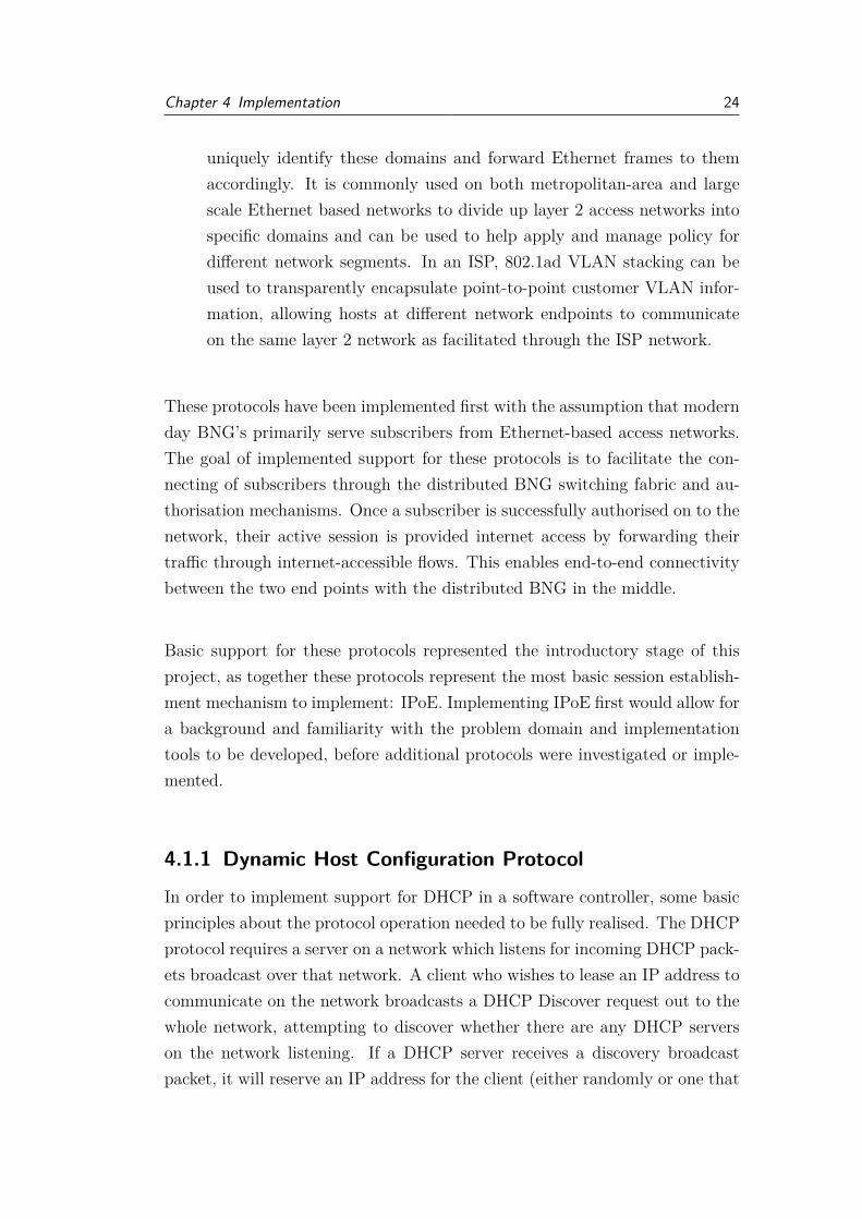
Chapter 4 Implementation 24
uniquely identify these domains and forward Ethernet frames to themaccordingly. It is commonly used on both metropolitan-area and largescale Ethernet based networks to divide up layer 2 access networks intospecific domains and can be used to help apply and manage policy fordifferent network segments. In an ISP, 802.1ad VLAN stacking can beused to transparently encapsulate point-to-point customer VLAN infor-mation, allowing hosts at different network endpoints to communicateon the same layer 2 network as facilitated through the ISP network.
These protocols have been implemented first with the assumption that modernday BNG’s primarily serve subscribers from Ethernet-based access networks.The goal of implemented support for these protocols is to facilitate the con-necting of subscribers through the distributed BNG switching fabric and au-thorisation mechanisms. Once a subscriber is successfully authorised on to thenetwork, their active session is provided internet access by forwarding theirtraffic through internet-accessible flows. This enables end-to-end connectivitybetween the two end points with the distributed BNG in the middle.
Basic support for these protocols represented the introductory stage of thisproject, as together these protocols represent the most basic session establish-ment mechanism to implement: IPoE. Implementing IPoE first would allow fora background and familiarity with the problem domain and implementationtools to be developed, before additional protocols were investigated or imple-mented.
4.1.1 Dynamic Host Configuration Protocol
In order to implement support for DHCP in a software controller, some basicprinciples about the protocol operation needed to be fully realised. The DHCPprotocol requires a server on a network which listens for incoming DHCP pack-ets broadcast over that network. A client who wishes to lease an IP address tocommunicate on the network broadcasts a DHCP Discover request out to thewhole network, attempting to discover whether there are any DHCP serverson the network listening. If a DHCP server receives a discovery broadcastpacket, it will reserve an IP address for the client (either randomly or one that

Chapter 4 Implementation 25
a client has requested) from a pre-determined pool of addresses, before sendinga broadcast DHCP Offer packet back into the network in reply. Although thispacket is broadcast to the entire network, it contains the clients unique MACaddress in order to differentiate this offer between any other DHCP offer pack-ets being actively exchanged to other hosts. Once this DHCP Offer packet isreceived by the original client, the client then makes an official request for thataddress and broadcasts it onto the network once again this time as a DHCPRequest packet. The request packet is handled in this fashion so that any otherDHCP servers which may also have responded to the initial discovery packetwith their own offer are notified of which lease the client is accepting and cansubsequently withdraw any unwanted respective DHCP offers and return thereserved IP addresses back into their pool. Finally, the DHCP server com-pletes the establishment phase by replying to the DHCP Request packet witha broadcasted DHCP Acknowledge packet, which contains lease informationand completes the IP-lease negotiation once received by the requesting client.A client which reaches this state now applies its leased IP address and is subse-quently free to participate in the network. This basic negotiation process canbe referred to as the DHCP DORA (Discover, Offer, Request, Acknowledge)handshake.
The DHCP protocol also supports features other than the basic IP addresslease negotiation sequence which need to be considered. These features in-clude variable-length packet embedded DHCP options and also the basic IPlease termination or rejection control phases. To offer a regular level of supportfor the DHCP protocol, these would needed be implemented in the controlleralso.
The DHCP implementation approach uses specific flows to facilitate the sub-scriber IP lease negotiation process. The created flows are crafted to know howto direct broadcast traffic matching specific user datagram protocol (UDP)source and destination port numbers to the DHCP server itself, and the con-troller knows how to return those responses back to the subscriber. Addition-ally, the controller is able to extract specific options from the DHCP packetsthemselves. Most importantly, among the different options is DHCP option53, used to facilitate IP lease negotiation message passing. DHCP option 53(titled ‘DHCP Message type’) is a one byte option appended to a DHCP packet

Chapter 4 Implementation 26
which indicates the purpose of that DHCP packet, e.g. a DHCP Discover orOffer packet. By reading the DHCP packets option 53 value and the associatedUDP source and destination port numbers, the controller is able to determinewhat the purpose of the packet is and can handle it accordingly.
The first thing the developed controller does is establish connectivity with theDHCP server (using the mechanism outlined in Section 4.3) and maintains thisawareness of how to reach it. The developed controller operates reactively andindividually handles each subscriber’s IP negotiation process as the controllerreceives packets forwarded to it from any switches for the purposes of flowmatching. Packets which are sent to the controller matching the criteria ofa DHCP Discover (DHCPD) packet initiate a DHCP handling process. Thisprocess is depicted in Figure 4.1. First, the controller polls or queries any con-nected AAA services (discussed in Section 4.2) in order to establish whetherthe source MAC address of the received packet belongs to a valid subscriberwith a specified connection type (i.e. DHCP or VLAN). The AAA service isexpected to return a true or false value. If the MAC address is unknown tothe service, it is blacklisted and future packets from that MAC address aresubsequently dropped. If the subscriber ends up being valid, the AAA ser-vice also returns the specified service type of that subscriber to the controllerfor processing. Using this data, the controller is then able to create a flowentry to facilitate that connection type. A corresponding DHCP flow entryis specified in Table 4.1, which would be used to facilitate broadcast-basedcommunication between the subscriber and DHCP server. Of note is the UDPsource/destination port combination, which are used by the requesting clientto deliberately target DHCP servers listening on those ports as per the pro-tocol specification. Once this control flow is established, the controller thenforwards the originally received DHCP Discover packet on to the DHCP server.
Ethernet Ethernet EtherType IP Protocol UDP source UDP dest.source MAC dest. MAC port port
[subscriber sourceMAC address] ff:ff:ff:ff:ff:ff 0x0800 [IP] 17 [UDP] 68 67
Table 4.1: Packet characteristics for matching DHCP control flow entry
Once the controller has facilitated broadcast-based communication between

Chapter 4 Implementation 27
Figure 4.1: Controlled DHCP session establishment process
the subscriber and the DHCP server using these control flows and forwardedthe intercepted DHCP Discover (DHCPD) packet to the server, the serverthen continues with next stage of the IP lease negotiation process. With theauthenticity of the subscriber confirmed, the DHCP server is now free to replywith a DHCP Offer (DHCPO) to the subscriber. The subscriber’s subsequentDHCP Request (DHCPR) packet which is sent in response is automaticallysent through the existing control flow to the DHCP server. If something hasgone wrong, the very same control flow can be used to forward the DHCPserver a DHCP Decline packet (in the event of an IP address conflict) startingthe process again, or alternatively the DHCP server can send a DHCP Nakto the client through the controller. However, assuming that everything hasgone correctly, the DHCP server should respond with a DHCP Acknowledge(DHCPA) packet. A flow to automatically facilitate this DHCP Acknowledgehas been deliberately withheld at this point, so that the switch is forced to

Chapter 4 Implementation 28
forward the packet to the controller. A DHCP Acknowledge packet forwardedto the controller indicates that the DHCP lease negotiation process is finalisedand the controller is able to create new flows that enable subscriber traffic tobe forwarded through to a edge IP router or wide area network (WAN). An ex-ample of these WAN accessible flows are presented in Table 4.2. Additionally,the control flows which initially facilitated the IP address lease are removedfrom the flow tables as they are no longer required. Finally, the controller thenforwards the final intercepted DHCP Acknowledge packet to the subscriber tofinish the negotiation.
Flow Match fields Priority Actionsclient-to-WAN in port=[subscriber accessible switch port], 100 output:[WAN
eth src=[subscriber source MAC address] accessible switch port]WAN-to-client eth dst=[subscriber source MAC address] 101 output:[subscriber
accessible switch port]
Table 4.2: Example flow entry pair for subscriber WAN access
The controller deliberately does not retain the DHCP control flows that wereoriginally created to aid in the IP lease negotiation phase. If these controlflows were to be retained by any switches, the DHCP control flow count wouldgrow at the rate of (n*2 ) per subscriber, which is unsustainable for limited sizeflow tables. However, the controller retains the ability to individually facili-tate and forward additional DHCP control packets by way of specific handlersconstructed to handle certain DHCP packets on an isolated basis. An exam-ple case of a packet which would have otherwise used an existing control flowis the DHCP Release packet, which is a subscriber initiated mechanism forsurrendering a leased IP address. During the development of these mecha-nisms, regular network operation was an assumption that was made. If theassumption is correct and the bulk of the DHCP server’s activity is facilitatingnew IP leases using control flows, then the remaining DHCP edge case packetsbeing forced to traverse through the controller (albeit at a much slower thanline-speed rate) is an acceptable compromise.
The installed WAN accessible flows are responsible for facilitating two waycommunication between the WAN edge and the subscriber. They function as‘catch all’ default flows for each subscriber in order to capture all subscriber

Chapter 4 Implementation 29
non-authentication/authorisation traffic and are subsequently assigned mod-erately low priority values. As mentioned in Section 2.1, priorities can be usedto determine an order of precedence for a flow over another similar or partiallymatched flow. A moderately low flow priority value means these WAN flowsare used when no more specific flows are installed. The WAN edge device endpoint in this instance functions as the handover to a different network, andis able to resolve the correct subscriber for any traffic destined to it by usingAddress Resolution Protocol (ARP) to resolve the destination IP address tothe appropriate subscriber MAC address. A subscriber which reaches the stateof having associated installed WAN flows is considered to belong to a basicWAN-accessible tunnel and therefore has internet or WAN access.
4.1.2 Virtual Local Area Network
By default, Ethernet frames which do not have deliberately tagged VLAN IDstypically are tagged on VLAN ID 1, the standard default VLAN. The use ofmultiple VLANs enables the division of the network into subsets of layer 2broadcast domains, allowing administrators to reduce the total broadcast traf-fic occurring on the network by limiting the areas in which broadcast traffic isable to propagate. Administrators are able to append VLAN tags to Ethernetframes by configuring specific switch ports to tag egress (outgoing) frames re-ceived from a connected host with specific VLAN IDs. These same tags areable to be stripped by the switch from ingress (incoming) frames destined forthe host in the opposite direction on the very same switch port. Ports withthis VLAN functionality are known as ‘untagged’ or ‘access’ ports. For in-stance, an untagged frame coming from a host to a VLAN 10 access port willbe subsequently tagged with the VLAN 10 tag as it passes through the port.If a VLAN 10 tagged frame attempts to reach the originating host from theother side of that same switch port, the VLAN 10 tag is stripped from theframe in order to be received by the host on the default VLAN (VLAN 1).Other VLAN port configurations include the following:
• Tagged portTagged VLAN ports are ports which are able to pass Ethernet frameswith existing VLAN tags already appended to them intact without ma-nipulating the tags themselves. These ports need to be configured to de-

Chapter 4 Implementation 30
termine which VLAN ID tagged frames may pass through them. Taggedports are often referred to as trunk ports, as often they often facilitateswitch-to-switch communication via uplink ports which permit the trans-port of many different VLANs through the same port.
• Hybrid portHybrid VLAN ports are a combination of both access and tagged VLANports. Hybrid ports allow the untagged port functionality for a specifieddefault VLAN (i.e., VLAN ID 1) and also the tagged port functionalityfor other defined VLANs. For instance, a hybrid port may be configuredsuch that default untagged frames entering the port are tagged ontoVLAN 10, while at the same time the port allows free passage to thoseframes which may already have VLAN ID tags 20 or 30. Commonly,Voice over Internet Protocol (VoIP) VLANs are configured as hybridports to support the ability to connect additional network hosts off of aVoIP handset while retaining VLAN isolation.
Figure 4.2 gives a basic visual depiction of how the untagged port and taggedport basic concepts can be applied to an actual switch with hosts. In thisexample, ports 1-3 on both switch A and B are configured as ‘untagged’ for
Figure 4.2: Example of basic VLAN port configurations

Chapter 4 Implementation 31
their own colour-coded respective VLANs. Port 4 of each switch is configuredas a ‘tagged’ port and allows frames tagged with VLAN ID 10, 20 or 30 to tra-verse the link between switches. In this example, assuming each PC is passinguntagged frames to the switch, PC A and PC D would be able to communicatewith each other in the isolated VLAN 10 broadcast domain network subset,PC B and PC E in the VLAN 20 network, and finally PC C and PC F in theVLAN 30 network.
In order to facilitate the configuration of switch ports in this project, thecontroller has been supplemented by a VLAN configuration file which admin-istrators are able to configure to specify the VLAN configuration for each ofthe switch ports governed by that controller. The port configurations are ex-tracted from a local .YAML configuration file and are parsed and applied bythe controller to their associated ports when the controller is first initialisedduring start up. Using this configuration file, the controller is also able toapply blanket catch all default VLAN configurations, as well port specificVLAN-exclusions. This introduces a similar level of configuration capabilityas is present in enterprise switches.
The current state of VLAN support in the controller is the ability for man-aged switches to facilitate and pass VLAN tagged frames through specificports. The frames are intercepted and forwarded to the controller in exactlythe same way as regular frames. The controller possesses the ability to strip(or pop) the VLAN tags from the frames and make decisions based on thetag values accordingly. Using a subscriber service type awareness mechanism(described in Section 4.2), the controller is able to subsequently create flowrules to send traffic matching specific VLAN tag values to specific locations oralternatively forward specific subscriber traffic based on the extracted VLANtags. Additional work is still required to fully implement support for packetswhich are required to be forwarded on by the controller, in accordance withthe VLAN restrictions associated with each port. Additionally, the ability toaccommodate more complex VLAN configurations such as VLAN stacking us-ing this controller is another feature that has not been able to be implemented,and is discussed in Section 5.3.1.

Chapter 4 Implementation 32
4.2 Dynamic Flow CreationIn carrier networks, the typical role of AAA servers is to act as a securityarchitecture responsible for controlling and managing subscriber access to spe-cific services (authentication, authorisation) and actively tracking the resourcesthat those subscribers are using (accounting). Two of the most common im-plementations of AAA in carrier networks are RADIUS [20] and Diameter[21]. In this project, a centralised subscriber information database was im-plemented to interface with the developed controller in order to perform basicAAA functions. Using this subscriber database allows the controller to extractaccurate information about known subscribers, their unique identifying con-nection information, and how their incoming session establishment requestsshould be handled by the controller and associated switching fabric. The con-troller is able to use this information to structure the creation of flows to meetthe requirements of each subscriber, in a mechanism termed ‘dynamic flowcreation’. Dynamic flow creation enables the controller to query for the appro-priate way to handle a given subscriber and then create flows to forward thetraffic of those subscribers according to their purchased or selected service. Forinstance, the source MAC address from an intercepted packet can allow dy-namic flow creation to facilitate the creation of flows to lease the subscriber anIP address through DHCP or alternatively forward future layer 2 traffic fromthat subscriber through a tunnel to a remote endpoint such as a satellite office.
The subscriber database was implemented as an Apache Cassandra [37] database.Apache Cassandra is a NoSQL database, with practical advantages such assupport for high availability, scalability and real-time input/output. NoSQLdatabases are a good fit for interfacing with network controllers given the ad-vantages gained from simpler data structure designs, scale-out architecturesand operational agility when compared to traditional relational databases.Apache Cassandra also supports a number of Python database drivers andAPIs, allowing Apache Cassandra to interface seamlessly with any controllerdeveloped using Ryu. Apache Cassandra was specifically chosen for a proof ofconcept subscriber database given it can easily scale to run across a cluster ofdatabase instances on multiple physical hosts. In order to avoid reintroduc-ing a SPOF into a developed SDN-enabled architecture this was an importantconsideration and ensures high availability of the database, allowing Apache

Chapter 4 Implementation 33
Cassandra to scale to the production network requirements as necessary.
Different protocol header and data values can be extracted from unmatchedpackets sent to the controller for governance. Using this data, controllers areable to make decisions about how to accommodate or cater for future trafficmatching these packet criteria using flows, in accordance with what rules havebeen explicitly defined inside the controller. By interfacing with a subscriberdatabase, the controller gains an extended awareness of how to handle specificsubscribers whose packets may not contain any special indicators which maybe used to individually determine the flows required for the subscriber. This isespecially important for an ISP, as subscribers may require a variety of differ-ent services with varying levels of support. Introducing a subscriber databaseallows network administrators not only to authoritatively control the ways inwhich subscribers are handled from a centralised point, but also provides aplace to store relevant information about subscribers which may not have abearing on how their packets are managed, such as active connection informa-tion. Furthermore, since flows are created based on the information extractedfrom the database at flow creation time, administrators gain the additionaladvantage of being able to update subscriber information without needing torestart the controller to begin applying their changes. However, this carriesthe caveat of not applying to any existing installed flows, only those whichare created after the change is made. Additionally, a centralised subscriberdatabase facilitates the construction of a database front-end portal which canbe used to make self-service or service desk changes easily.
4.3 Anonymous Unicast Host DetectionIn order to accommodate limitations imposed on the project by the simula-tion of a network in the lab environment, connectivity extensions were writteninto the Ryu controller to allow the controller to maintain connectivity withstaticly connected hosts, i.e. a DHCP server or an IP router on the WANedge. These changes were necessitated by the presence of OVS in the net-work topology rather than an actual real-world commodity switch. With acommodity switch in a real world carrier network, network administrators areable to maintain an awareness of how their networks are physically laid out,

Chapter 4 Implementation 34
including configurations for the ports which carry traffic to and from specificappliances, servers or services. Using OVS and a virtualised host lab, this spa-tial awareness was not always easy to achieve. Connected virtual hosts werenot consistently connected to persistent OVS virtual switch ports and in thedevelopment environment often appeared to change port bindings dynamically.Any flows which required the forwarding of packets to specifically targeted ap-pliances needed an awareness of which virtual ports were associated with thoseappliances. Subsequently, a reliable mechanism to bind these hosts to thoseports in order to facilitate those flows was required in the controller.
As briefly mentioned in Section 4.1.1 ARP acts as a layer 2 MAC-to-IP ad-dress lookup, where a requesting host floods the layer 2 network to request theidentity or location of a host matching a specific IP address. The ARP requestpropagates across the entire layer 2 network. If the requested host receives theARP request, they reply to the requesting host with the required informationin a specifically targeted response. This enables the creation of a binding ofthe responding hosts MAC address to the requested IP address in the origi-nal host’s ARP table. Additionally, since the response message traverses thelayer 2 network in order to reach the original host, any intermediary layer 2switches between the hosts learn forwarding information about which switchport best reaches which host (the newly identified host in addition to both therequesting and responding hosts). ARP forms the basis of the host detectionmechanism in the controller developed for this project.
The resulting mechanism to bind dynamic ports to specific appliances func-tions similarly to an anonymous unicast transmission. A unicast transmissionin this context is the sending of one-to-one messages to a specific networkdestination as identified by a unique address. Using a generated unicast trans-mission allows the controller to maintain port binding information about ap-pliances which the controller and the switches are required to interface with.The controller does this by binding switch ports in software to correspondinghosts that generate specific protocol responses to an input. This approachrelies on sending an ARP packet from the controller across the layer 2 net-work to target specific known appliances. Since the Ryu software controllerwill not apply controller-specified rules to any packets destined for the con-troller itself (as traffic targeting the controller specifically already matches an

Chapter 4 Implementation 35
Figure 4.3: Anonymous unicast flooded ARP request example
existing hidden control flow), the controller requires a mechanism to interceptcontroller-destined traffic and handle it accordingly in software. The ARPheader of the flooded packet contains fictitious source MAC and IP addressesin order to force the target host into responding with an ARP response to ahost who does not actually exist. Since the specified host does not exist, thesepackets are forwarded to the controller instead. This allows the controller toreceive any ARP response packets generated by the targeted host upon receiptof the original flooded ARP packet, as they are sent to fictitious addresses withno corresponding flows to handle them. To the controller, these packets aredestined for a host for which a flow does not already exist and therefore aresent into the software controller for a flow lookup. Subsequently, the controlleris able to determine which virtual port the targeted appliance has replied from,and can save this information for later use. A depiction of this process is pre-sented in Figures 4.3 and 4.4.
In Figure 4.3, the controller is flooding the original ARP request from thedirectly connected switch and onto the layer 2 network. The crafted ARPrequest contains information the network administrator already knows, suchas the destination IP and MAC address of the appliance that the controlleris targeting. Since the controller does not however know where this host is,

Chapter 4 Implementation 36
Figure 4.4: Anonymous unicast ARP response example
it spoofs the source MAC and IP address inside its ARP request to elicit anARP response to these addresses. This way, the controller can coerce thetargeted appliance to reply to the fictitious address, allowing the controllerto intercept the response. The controller recognises the spoofed destinationMAC and IP addresses and saves the port information associated with the in-coming packet. The generated ARP response process is depicted in Figure 4.4.
The anonymous unicast mechanism would not be necessary in a real-worldenvironment. However, its development was required to accommodate the dy-namic port allocation that was experienced with simulating layer 2 switchesand interconnected hosts. The anonymous unicast mechanism enables thecontroller to deliberately and forcibly learn which virtual port specific appli-ances can be accessed through. Without this mechanism, the controller wouldonly be able to learn about this port association if the appliance were to sendpackets through a connected OpenFlow-enabled layer 2 switch for the firsttime. Given that this project attempted to simulate a carrier network, onlyhaving an awareness of where appliances lay in the network once they startedgenerating traffic on their own accord was considered an unnecessary sessionestablishment time delay.

Chapter 4 Implementation 37
It should be noted that there were a number of other OVS virtual port per-sistence mechanisms discovered later in the development cycle of this project,such as the ability to persistently bind virtual ports to virtual host interfacesin the OVS underlying database. However, the implemented anonymous uni-cast host detection mechanism still lends itself well to other circumstances. Ina complex OpenFlow-enabled network topology, a given controller is not ableto determine the port binding information for a virtual switch being governedby a different controller. In that situation, any connection information forthat switch remains solely accessible to that controller. The anonymous uni-cast host detection mechanism allows an administrator to expose the necessarypath for a given controller to take to reach a desired target host, irrespectiveof the virtual switch that the host remains connected to.

Chapter 5
Evaluation and Discussion
5.1 Broadband Network Gateway SessionAggregation
5.1.1 Dynamic Host Configuration Protocol
Evaluation
One problem with the implemented DHCP session establishment mechanismis the lack of controller support for easily parsing extended DHCP options. Inorder to facilitate the most basic IP lease negotiations, the only option thatwas able to be supported in the controller was DHCP option 53, the DHCPMessage Type option. While the ability to parse other one byte options may beeasily implementable, any other appended DHCP options of a greater lengththan one byte would require a new controller mechanism for that option tobe read or extracted by the controller individually. As a result, the ability tosupport many important DHCP options which are used to establish IP leaseswith specific, non-default properties and make subsequent forwarding decisionsbased on that information is diminished. For instance, DHCP option 51 titled‘IP address Lease Time’ is a four byte option which enables a DHCP serverto indicate inside a DHCP packet the time (in seconds) in which the clientis permitted a leased IP address before that lease expires and an IP addressrenegotiation will need to take place. If this option were to be supported in thecontroller, it could be used to populate subscriber flow expiration time framesand allow flows to expire alongside the IP address lease they were originallyassociated with. A renewal of the IP address lease would renew the flow tiedto it, which would automate the expiration of unused flows. In the meantime,

Chapter 5 Evaluation and Discussion 39
such flows need to be manually retired upon receipt of a DHCP Release packet.Unfortunately, a number of hosts do not release their IP leases this way andsimply disconnect from the network, meaning that without an automated flowexpiration system a significant number of subscriber DHCP flows may existuntil manually removed.
The existing mechanism designed to handle DHCP traffic in this controllerlends itself well to the maintenance of authoritative subscriber information.All DHCP server responses to the DHCP client pass through the controllerand, although this introduces some latency, it enables the controller to extractIP lease negotiation data from the packets themselves. Session data obtainedin this way can subsequently be written into the database as a mechanismof maintaining current up-to-date information on a subscribers active internetsession. The immediately implementable examples of client, server and gate-way IP addresses come directly from the DHCP packet themselves. Each canbe helpful for administrators to monitor a particular subscriber session andcan be added to tools to aid with ISP operation, administration and man-agement (OAM). In the instance of multiple network end points or multipleDHCP servers, this extracted network information can allow an administratorto gain an immediate view of which IP address is being used by a subscriber,which server leased the IP address, and which network gateway the subscribertraffic is being forwarded through. Additional subscriber session capabilitiesand information can be further extracted if more flexible DHCP option han-dling is implemented in the controller.
Discussion
There are improvements that could be made to the supported DHCP function-ality in order to reduce latency associated with IP address lease negotiation.Currently, each DHCP control flow which is used to forward subscriber DHCPpackets to the server are installed on an individual basis, pending a successfuloutcome from a subscriber service type handler query made on the subscriberdatabase. A substantial speed improvement to flow creation could be realisedif there was single default catch-all DHCP control flow used to facilitate allIP lease negotiation with a DHCP server. Using a single control flow wouldsave controller processing power, throughput and time on flow creation rates

Chapter 5 Evaluation and Discussion 40
(which as discussed in Section 3.1.1 is an inherent limitation of using the Ryucontroller). A single DHCP control flow would be able to forgo the creationand deletion of DHCP control flows in quick succession for each DHCP clientas they attempt to lease an IP address through the controller. However, anew mechanism which is able to differentiate between IPoE service subscriberswho are authorised to obtain an IP address through DHCP and those whoauthenticate though a different mechanism (i.e. PPPoE) would need to beimplemented in the controller. This is an important security capability as ituses OpenFlow flow creation to isolate subscriber traffic into specific flows andallows administrators to ensure subscriber traffic is only permitted access tothose services or appliances which are required for them to gain WAN access.Additionally, such an approach would see the loss of the controller’s ability tomanually expire flows based on the receipt of a DHCP Release packet. If theDHCP Release packet is no longer received by the controller and instead isforwarded immediately through to the DHCP server, deliberate IP lease ex-piration will happen without the knowledge of the controller. Subsequently,leases may expire independent of expiring the associated flows, which overtime may lead to flow tables filled with inactive, unused flows. Given the ad-vantages of the installation of a single DHCP control flow, this avenue shouldbe investigated further. However, it would require the re-engineering of thiscontroller further to accommodate for the problems that it would introduce.
5.1.2 Virtual Local Area Network
Evaluation
One weakness of using a configuration file to determine individual VLAN portconfigurations is the reduced ability to make dynamic changes to VLANs inan OpenFlow-enabled network. This is because VLAN configurations are onlyapplied to specified ports at the time that the controller is originally initialised.Subsequently, any changes to port specific VLAN configurations (either ma-jor or minor) will require the entire controller to be re-initialised or restarted.While this is not a substantial undertaking and only carries the disadvan-tage of delaying flow creation by the time it takes the controller to restart,it can make network administration problematic. Network administrators arecurrently in the position to determine port configurations on any commod-ity switches independent of other switches, and can immediately have those

Chapter 5 Evaluation and Discussion 41
changes applied in a production network environment. Although an authori-tative controller architecture introduces the advantage of centrally managingswitches, the ability to easily deploy any changes immediately is lost. In orderto preserve both characteristics using the developed controller, a mechanismwould need to be implemented to allow the dynamic VLAN modification ofswitch port configurations.
Unfortunately, full VLAN support that accommodates the preservation ofVLAN information when packets are intercepted and forwarded on by thecontroller was not implemented. This feature would require the controller todetermine which ports or hosts specific received packets were permitted to beforwarded to, based on the VLAN configuration of the port or host the packetwas received from and the port or host the packet was otherwise destinedfor. This could be accomplished with some work by using the VLAN config-uration file and a controller forwarding table to determine whether a packetsidentifying characteristics would be permitted en route to its destination, aswell as what outgoing port VLAN configuration must be applied the Ethernetframe encapsulating the packet. Additionally, greater support for more com-plex functionality (i.e. 802.1ad VLAN stacking) could be implemented oncethe VLAN support in both Ryu and OpenFlow is improved.
Discussion
Attempting to dynamically modify switch port VLAN configurations is moredifficult than it seemingly appears. It is not simply a challenge of discoveringthe best way to deploy any port VLAN configuration changes to an activecontrolled switch in a production network. The other important considerationrequiring investigation is how any VLAN configuration changes alter or im-pact existing installed flows in the switch flow tables. Modification or removalof VLANs from ports may prevent previously existing flows from successfullyforwarding packets through to specific end points. One way to accommo-date this situation is a controller function which compares the existing flowtables and determines where VLAN configuration changes will impact thoseflows, triggering handler or modification events in response. Such events mayinclude immediately expiring previously matching flows by overwriting theseexisting flows with identical flows with an immediately expiring flow timeout.

Chapter 5 Evaluation and Discussion 42
This would force the flows to be subsequently re-established via the controller,which would be aware of the updated VLAN configurations. If any formerflows were still actively forwarding packets when they were forcibly expired,they would be automatically re-established upon receipt of the first packet notalready matching a remaining flow. At this point the controller could receivethese packets and create new flows in accordance with the updated VLANconfiguration. Upon successful flow creation, regular operation would resume.
5.2 Dynamic Flow CreationEvaluation
The subscriber database for dynamic flow creation is currently accessed di-rectly through the controller. Depending on the flow-creation rate, this couldintroduce a bottleneck in the developed architecture, especially since the con-troller platform is currently not distributed. The controller would be requiredto sequentially query the database a substantial number of times for eachunhandled subscriber packet that reaches it in order to accommodate flow cre-ation for each associated subscriber. Given the poor throughput performanceof the Ryu controller in high rate flow creation tests [33], placing additionaloperational strain on the controller by forcing it to interface with a subscriberdatabase on a flow-by-flow basis may further compound the performance prob-lems. A potential solution is rewriting the controller logic to dynamically createflows for all known subscribers during controller initialisation instead of duringoperation. This in itself is not a perfect solution however as there is poten-tial for the installation of flows to accommodate subscribers who may not becurrently active but none-the-less remain in the database. This additionallyresults in increasing the number of flows being installed in flow tables. It maybe possible to use multiple fallback flow tables to accommodate these highnumbers of installed flows, but this requires further investigation. Further-more, a mechanism would need to be developed to update the controller withany new or modified subscriber handling conditions which may be insertedinto the database after the controller has already been initialised to ensureflow tables and the database subscriber flows are synchronised.

Chapter 5 Evaluation and Discussion 43
Discussion
In a real world carrier network, there may not always be an authoritative sub-scriber database from which to draw information about how to handle specificsubscribers. More commonly, this information can be sourced from existingAAA services. The implemented subscriber database presented in this projectshould be considered as a supplemental extra that accommodates the exchangeof information for large numbers of subscribers on a wide range of different ser-vices. Depending on how subscribers are handled by their respective serviceAAA server, a central subscriber database may help by introducing a centralpoint to manage subscribers across all services. Such an extension would al-low a subscriber database to function as a modular add-on to existing AAAservices, while supporting subscriber management through a single authorita-tive source. For instance, a subscriber database could interface with a DHCPserver to facilitate the leasing of static IP addresses that have been deliberatelyspecified in the database for a given subscriber. This configuration would beapplied to the DHCP server each time a change was made in the databaseand would apply to subscribers once the subscriber made an IP address leaserequest.
5.3 Project and Technology Limitations orDifficulties
There were a number of limitations and difficulties discovered during the imple-mentation of the project. These manifested as issues with the protocol supportof the simulation environment, technical limitations of the software controllerframework, and common developmental issues with documentation and bugs.This section details these limitations and difficulties and their overall effect onthe project outcomes.
5.3.1 802.1ad VLAN Support
The OVS virtual switch is an ongoing work in progress which aims to en-able network automation in a programmatic way, facilitating the innovationof smarter ways for networks to operate by network operators and researchers

Chapter 5 Evaluation and Discussion 44
alike. Much like OpenFlow, new features and supported protocols are contin-ually being introduced regularly into OVS with subsequent version updates.However, one notable omission to the OVS framework as of the writing ofthis report is support for the 802.1ad Ethernet standard [30], also known asprovider bridging, stacked VLANs, or Q-in-Q. The 802.1ad standard intro-duces the ability to append multiple VLAN tags onto a single Ethernet framein a standardised way, allowing for more complex network topologies. Carriernetworks that support 802.1ad enable a service provider more flexible for-warding capabilities such as the ability to separate, encapsulate and transportcustomer VLANs across a service provider network without compromising theISPs network operation. Stacked VLANs is commonly used in carrier networksto support metropolitan Ethernet configurations, much like the New ZealandUFB Fibre network. Stacked VLANs also gives network operators the abilityto receive multiple VLAN-tagged Ethernet frames which can be used to distin-guish the upstream provider, handover port or service that a given Ethernetframe was received on. Subsequently, sequences of identifying VLAN tags canbe used to determine specific subscribers and the network path that their traf-fic has taken to arrive at the ISP. A visual representation of this topology froma UFB Retail Service Provider (RSP)’s perspective is provided in Figure 5.1.
Figure 5.1 depicts a point-to-point connection occurring over an optical fibreaccess network. A CPE sits at the edge of the access network and acts as thepoint-of-presence for the subscriber in the access network topology. Traffic thatleaves the CPE may be encapsulated with a customer VLAN identifier (CVID)tag, meant to be handled at another remote location. An optical network unit(ONU) switch aggregates the optical connections from each subscriber’s Op-
Figure 5.1: 802.1ad operation in an ISP network

Chapter 5 Evaluation and Discussion 45
tical Network Terminator (ONT) within in a common geographic area. Oncea session hits the ingress port of the ONU it is affixed with a Service VLANIdentifier (SVID) or SVLAN tag. These sessions are then transported throughthe local fibre carrier (LFC) network where decisions about where to forwardthe traffic can be made at each of the intermediary access switches or Ethernetaggregation switches (EAS) (based on the VLAN tags). Finally, frames fromthe originating session are received at the RSP handover as doubly-taggedSVID:CVID frames. These frames appear to the RSP at this point in theconfiguration depicted in Table 5.1.
(8 Bytes) (6 Bytes) (6 Bytes)Preamble Destination MAC Source MAC
... ff:ff:ff:ff:ff:ff de:ad:be:ef:00:00
(4 Bytes) (4 Bytes)802.1q SVID Header 802.1q CVID Header0x88a8 0x014d [333] 0x8100 0x0063 [99]
(2 Bytes) (n Bytes) (4 Bytes)EtherType Payload CRC/FCS
0x0806 ... ...
Table 5.1: Basic 802.1ad VLAN-stacked ARP packet
At this point, the traffic can be forwarded across the RSPs network to theintended recipient. Using a series of tags in this fashion enables a BNG to popeach tag individually and make subsequent decisions based on their values. Forinstance, the BNG may have a series of rules to say that if the original CVIDtag is VLAN ID 1, then to treat it as regular traffic. Otherwise, if the CVIDtag matches a specific value, such as 99, to forward the frames to a specificlocation. The ability for a developed system to accommodate 802.1ad for thispurpose is critical for service providers that provide point-to-point or WANsolutions for subscribers.
Although OVS does support the ability to accommodate double-tagged framesin a non-standardised pre-802.1ad way, this can lead to issues in some ISPnetworks. Many LFC network handovers present egress frames to RSPs as802.1ad frames, and due to 802.1ad compatibility issues, RSPs then modifythe 802.1ad VLAN header to convert it into a regular 802.1q VLAN header,

Chapter 5 Evaluation and Discussion 46
in order for that frame to be supported by the RSP network. Before a 2011amendment, the 802.1q standard determined that in the tag control informa-tion (TCI) portion of the VLAN header (between the EtherType and VLANID), the bit immediately preceding the VLAN ID (called the Canonical FormatIndicator bit, or CFI) was used for indicating the compatibility of the taggedframe for older legacy networks. In an Ethernet network, this bit would alwaysbe set to 0. In 802.1ad, this same bit (now named the Drop Eligible Indica-tor bit, or DEI) is used for a different purpose, namely determining whetherany QoS policy (in the preceding bits of the TCI) should be used to ascertainwhether frames are eligible to be dropped by a switch in the presence of net-work congestion. In an ISP or RSP network with equipment conforming to thepre-2011 802.1q VLAN standard, dynamically changing an 802.1ad header toa 802.1q header in the aforementioned way can cause problems. If a networkadministrator is not careful, changing an 802.1ad DEI bit into a 802.1q CFIbit can cause any frame specific QoS policy to behave unpredictably. Given itis common to use VLAN CLI bits to determine network segment QoS policy,by conforming to the 802.1ad (or post 2011 802.1q) standard, OVS is able tosupport this standardisation for network interaction between handovers.
We assume that real world switches will not be subject to the same inher-ent VLAN restrictions that OVS currently is. While there are workaroundsto implement a VLAN configuration that supports multiple VLAN tags in asimilar mechanism to 802.1ad in OVS, these will not be necessary in a realcarrier network assuming the existence of modern layer 2 switching hardware.The lack of support for the 802.1ad standard is an inherent limitation of usingOVS as the simulating layer 2 switching fabric for this project. Subsequently,realistic and standardised ISP carrier network topologies using 802.1ad werenot able to be simulated for this project.
5.3.2 Controller Scalability
The Ryu controller framework does not currently support multi-threading.This is an inherent limitation to the project as without being able to scaleacross multiple CPU cores, the controller may be unable to keep up with thethroughput demands of a moderately sized carrier network. [33] demonstratedthat the Ryu controller framework was less suitable for enterprise deployment

Chapter 5 Evaluation and Discussion 47
after using throughput and latency metrics to determine whether Ryu was ableto scale to meet high network demands. These tests were performed across 32switches with up to 100,000 hosts. The results indicated that the failure ofRyu to accommodate these high numbers (when compared to other controllerframeworks) was a lack of multi-threaded capability. The best controllers sam-pled in the same research were multi-threaded and outperformed Ryu due totheir incoming message thread dispatcher algorithms. These controllers sawa higher degree of throughput performance as their CPU cores scaled to thenumber of connected switches. Such a positive correlation is impossible toachieve with the current iteration of Ryu as the number of CPU cores utilisedwill always be one, no matter how many switches are being actively managed.Subsequently, the use of Ryu to create a carrier network distributed BNG ar-chitecture is not feasible due to Ryu’s inability to handle large numbers ofhosts and switches.
5.3.3 Controller Distributivity
As briefly discussed in Section 3.1.1, there does not currently exist any mech-anism using the Ryu controller framework to achieve a truly distributed seriesof OpenFlow controllers. Although there is some consolation in the ability tointroduce redundancy into the controlling framework by use of a master/slaveconfiguration and Zookeeper, a distributed controller framework would bepreferable to implement in order to address the controller scalability issuesas discussed in Section 5.3.2. A single Ryu controller possesses the abilityto access a single CPU core at any given time, but extending that capabilitywith a distributed series of Ryu controllers presents an opportunity to addressthe challenges associated with using a single Ryu controller and typical carriernetwork throughput. This is one reason why the lack of controller distributiv-ity is a significant project limitation, as it continues to restrict the capabilityto introduce a system which will scale appropriately to carrier network re-quirements. Additionally, the ability to introduce distributivity into the Ryuframework offers not only high availability, but also efficiency and speed ad-vantages. While a prototype of a SDN-enabled distributed BNG architectureis possible without controller distributivity, its omission is a notable limita-tion of the capabilities of a new BNG architecture. The basic differences incapabilities between a distributed controller model and a redundant controller

Chapter 5 Evaluation and Discussion 48
model are shown in Table 5.2.
High ImplementationAvailability Scalability Speed Monitored Complexity
DistributedControllers x x x ? Very ComplexRedundantControllers x x Simple
Table 5.2: Distributed vs. redundant controller comparison
Table 5.2 indicates that distributed controllers introduce a greater feature setthan simple redundant controllers. Specific disadvantages of the Zookeeper-facilitated redundant model are failures to address scalability of the system(by having only a single controller handling all active subscriber flow creationat any given time) and the inability to leverage speed increases by deployingcloser to the physical locations of the subscriber base, subsequently reduc-ing flow creation and operational latency. These serve as limitations as thedeveloped controller will be much slower than the BNG appliance that it isattempting to improve upon. The Zookeeper model does however offer theability for monitoring systems to gauge the health of a redundant controllersystem through external event alerting which is helpful for system administra-tion.
Creating a distributed controller framework using Ryu would be a large re-search undertaking in its own right. Fortunately, there have been indicationsthat such research is currently under investigation. In the meantime, usingRyu with Zookeeper appears to be the only current approach to high availabil-ity, leaving remaining limitations unaddressed.
5.3.4 API Documentation
As is common when working with some APIs, the lack of extensive documen-tation for various components and API calls of the Ryu controller was a sourceof difficulty. The Ryu controller framework and codebase is documented welland there is a lot of support available through various forums and mailinglists. However, difficulties did arise when developing using software function-
Chapter 5 Evaluation and Discussion 49
ality that was not extensively documented and was only briefly mentioned inofficial resources. This led to a trial and error, guess and check developmentmethodology for a period of time, which was not effective or productive. Specif-ically, these difficulties affected the ability to easily de-capsulate the contentsof a packet such as both the headers and payloads of encapsulated datagrams,as well as dynamically extract variably sized DHCP options from DHCP pay-loads as noted in Section 5.1.1. Additional difficulties were experienced whenattempting to follow documentation that was not correct, leading to delayswhen specific software controller functions or methods did not work as docu-mented or expected. In some instances, the Ryu documentation was too vagueabout specific implementation details, which necessitated referencing back tothe OpenFlow switch specification to understand why Ryu functioned the wayit did.
5.3.5 Bugs and Software Regression
Ryu and OVS are open source projects and attract much attention from a wideaudience. Contributors to these projects range from researchers and academicsto enterprise network architects and industry experts. While most interest inthe project is of substantial benefit to each respective development community,it can lead to software bugs and regression. The basic definition of softwareregression is a software bug which stops a feature of a system working aftersome system event, such as an upgrade or patch. With such a large base ofcontributors, it is easy for unintended behaviours to be programmed into soft-ware by accident. This is despite the use of revision control systems and patchacceptance policies associated with both the OVS and Ryu projects. Softwareregression did unfortunately occur with the use of OVS in this project. Theapparent reintroduction of a bug in OVS caused difficulties with unpacking fullIP packet payloads. The problem manifested as the truncation of unbufferedpackets received by the Ryu controller framework which occurred when thepriority of the flow corresponding with the delivery of those packets was 0(a priority value typically reserved for packets which do not match any otherflows, known as a ’table miss’). Unbuffered packets in this instance are thosepackets which are deliberately sent fully intact to the controller for processing,as opposed to buffered packets which only contain a limited portion of theoverall packet in order to increase controller processing efficiency. For spe-

Chapter 5 Evaluation and Discussion 50
cific protocol packets where there is required information after the observed128 byte truncation point, this presented substantial development problems.DHCP packets were particularly affected, as the DHCP header is variablysized and a number of valuable variable length DHCP options are located inthe tail of that header. This was fixed by changing the priority value of thecorresponding DHCP traffic flows from 0 to any other priority. This bug wassubsequently re-reported to an OVS developer.

Chapter 6
Conclusions
6.1 Contributions MadeThis project has investigated the ways in which OpenFlow may be used to im-prove upon and address existing weaknesses and vulnerabilities in the existingcentralised BNG model. A basic design was implemented and presented thatoffers software controller support for two basic subscriber session establishmentprotocols. Additionally, a conceptual subscriber database was introduced toimprove the way in which session establishment protocols interface with AAAservices in order to dynamically forward subscriber traffic using OpenFlow.Along with these proposed OpenFlow controller designs which address somebasic distributed BNG concepts, this project has also investigated a numberof approaches and limitations which may be used to realise a fully operationalOpenFlow-enabled distributed BNG solution in the future, as the technologiesinvolved mature.
6.2 Future WorkGiven the scope of the implemented components of this project, there is alarge amount of subsequent work that can be carried out to develop a con-troller framework capable of functioning as a distributed BNG and operatinga basic production carrier network. Many of these facets were not simply over-looked during development, but remain as important considerations for futurework. Given the scope of a fully realised and implemented project capableof replacing a network model as inherently complex and well-iterated as the

Chapter 6 Conclusions 52
BNG, much work remains to develop a fully working prototype. The discussionof several of these remaining required components for developing a OpenFlow-enabled distributed BNG are detailed below. Many of them may be able toform the basis of projects such as this in their own right.
6.2.1 Additional Protocol Support
The OpenFlow protocol is a constantly evolving entity, which can be attributedto the operational flexibility OpenFlow affords to network administrators andthe increased interest in network virtualisation. Given the interest in theprotocol and SDN concepts, new features and supported protocols are beingintroduced into the standard on a regular basis. Subsequently, it is difficultto predict whether any introduced future features may benefit the approachesdiscussed in this project and, if they do, what the timespan to introduce thosefeatures may be. At the time of writing this report, the OpenFlow version1.5 specification was still being written, and version 1.4 is still not yet wellimplemented. Open Networking Foundation (ONF) members have suggestedthat this version of the specification will contain greater levels of support forcarrier network SDN, including support for carrier network OAM and the un-derlying technologies that enable it [16]. Once version 1.5 of the standard issupported in Ryu in full, it is possible that some of the underlying necessaryBNG supported protocols which are absent in existing OpenFlow specifications(as discussed in Section 3.1.2) will be introduced in some capacity. This couldmake an OpenFlow-enabled distributed BNG model for ISP carrier networksmore feasible by offering more complete support for the wide range of pro-tocols required to support media-agnostic modern-day ISP carrier networks.Other alternative options include the investigation or extension of the ROFLlibrary and bringing its capabilities to OpenFlow, OVS and Ryu. Access tothe protocols supported in ROFL could allow this project to further evolveinto a working prototype.
6.2.2 Flow Management and Operational Robustness
Networks have traditionally been able to operate dynamically and autonomously.This is due to the fundamental concept of connectionless networking, which

Chapter 6 Conclusions 53
determines how the transmission of data is achieved between two networkend points for which no dedicated paths exist. It is an important conceptto consider when designing traffic flows as depending on the nature of theflows, it is possible that specific network hosts are required to be traversed forend-to-end connectivity. Additional work is required to retain this importantconnectionless networking property and the overall operational robustness ofthe developed system. Many of the flows created by a distributed BNG con-troller will assume full end-to-end connectivity between network end pointsand may be installed in flow tables of any intermediary devices as such. Theproblem with this approach is the assumption that those hosts will remain upand operational, given that if any of the intermediary devices between two endpoints were to change or be lost, some end-to-end flows may fail to continueto forward traffic correctly. A dynamic flow-based system will be necessary toensure the loss of any intermediary hosts in an end-to-end path does not affectthe ability for the system to function correctly and forward traffic accordingly.
In the context of subscriber sessions and any corresponding installed flows,control mechanisms such as keep alives and timeout mechanisms still need tobe investigated. Each OpenFlow enabled device in a network topology willhave inherent restrictions on the maximum number of flows it is able to store.Assuming that there is a positive correlation between the number of active sub-scribers being aggregated through a distributed BNG and the number of flowsrequired to manage them, scaling to accommodate every single subscriber mayeventually be difficult. Subsequently, dynamic methods to manage sessions orflows that are not currently active should be implemented. These methodswill ensure that subscribers who are not currently active are expired from thesystem, using mechanisms such as DHCP lease expiration discussed in Section??. A subscriber re-establishing a connection through the BNG system canbe facilitated each time from scratch with minimal extra effort, so there is noproblem with liberally expiring sessions.

Chapter 6 Conclusions 54
6.2.3 Additional Authentication, Authorisation andAccounting Support
AAA servers in an ISP carrier network often operate as a function of the BNGappliance itself or as an external appliance which the BNG connects to andinterfaces with. Since the BNG functions as a common aggregation point forsubscriber traffic, this is a sensible architecture. AAA servers are required toauthenticate and authorise subscribers with respect to permitted or accessiblenetwork services, but also must account for the usage of those services by eachsubscriber. The proof of concept AAA approach presented in Section 4.2 hasbeen designed as an authoritative subscriber database. While useful for mak-ing dynamic traffic forwarding decisions, this database does not function asan extension to existing AAA services, but rather as a supplemental service.Substantial work is required to extend the developed controller AAA functionendpoints into a modular API-based design that allows for multiple protocolsto be supported, much like a BNG appliance would. Such an approach wouldallow for the extensible support of different carrier network configurations witha number of different AAA services. This subsequently would help accommo-date varying kinds of production carrier networks present in modern day ISPs.
6.2.4 Complex Network Topologies
Aside from the technical limitations of this project that were discussed in Sec-tion 5.3, there are a number of additional project components remaining whichwould require development to fully realise a distributed BNG implementation.Due to the developmental time constraints, expanded network topologies ofmultiple layer 2 switches and upstream network endpoints were not tested orevaluated during the development cycle. To support these topologies interme-diary devices would need a way to determine the logical layout of the network,as they would allow each OpenFlow-enabled switch to dynamically understandhow best to forward Ethernet frames to the correct end points. Additionally,a large network of layer 2 switches more accurately represents an ISP carriernetwork than the simple single switch topology used in the initial stages of thedevelopment cycle. This single switch topology does not require OpenFlow-enabled switch to switch communication, or introduce multiple upstream end-points. Once the project demonstrates a capability to forward Ethernet traffic

Chapter 6 Conclusions 55
within a larger topology such as this, it would be closer to developing a solu-tion which could be used in a basic production carrier network.
6.2.5 Real World Testing and Evaluation
An important component of developing a distributed BNG implementationis the testing and evaluation of any developed solution on real-world hard-ware with realistic production traffic. However, the use of different real-worldOpenFlow-enabled switches or production traffic flows may have the possibil-ity of introducing unexpected or unhandled behaviours to the controller. Awell-structured and thorough evaluation of a variety of BNG use cases is a nec-essary approach to evaluate the performance and practical feasibility of anydeveloped solution. Fortunately, OpenFlow is an enabler of such evaluations,permitting the execution of experimental protocols and implementations onreal-world production networks alongside regular network operation [18]. Us-ing such an abstract approach to evaluate experimental network modificationsenables network researchers and administrators alike to design comprehensiveunit-based tests for their experiments. These unit-based tests can be basedon any facet of the experiment design and, in the context of this project run-ning on a carrier network, could be used to individually assess and evaluatespecific protocols, processes or functions of the developed implementation. Un-fortunately, due to developmental time constraints, testing of this nature wasnot carried out for this project. To measure the success of this project or anyof the approaches outlined in this report, real world testing would be necessary.
6.3 ConclusionsThis project has focused on the operational flexibility provided to networkadministrators by the use of OpenFlow, via its centralised software controllerarchitecture. Centralised software controllers provide the ability to dynami-cally reconfigure switches in order to govern how traffic is forwarded, which canbe leveraged to explore and investigate potential solutions to shortcomings orvulnerabilities in existing network protocols and models. Given the limitationsdiscussed, it is not currently possible to introduce a comprehensive, scalableand complete distributed BNG solution using the OpenFlow controller software

Chapter 6 Conclusions 56
Ryu and OpenFlow version 1.3. However, some of the smaller controller de-signs and concepts introduced in this project are suitable for governing sessionestablishment mechanisms in smaller network environments, and can act as astarting point for future development of carrier-grade SDN components. Theshortcomings of developing a complete distributed BNG solution are due to thelack of scalability and carrier-grade high availability as a result of the inabilityto distribute the functionality of the Ryu software controller among multiplecontrollers, as well as necessary session establishment and network communi-cation protocols being not fully implemented in either OpenFlow or Ryu yet.However, if these problems were to be addressed (or a different, more suitablecontroller software framework chosen), the developed OpenFlow-enabled dis-tributed BNG architecture would be viable.

References
[1] ATM End-to-End Working Group. Core Network Architecture Recom-mendations for Access to Legacy Data Networks over ADSL (TR-025).Technical report, Broadband Forum, September 1999.
[2] Biondi, P. Scapy. http://www.secdev.org/projects/scapy/, n.d. [Accessed1 October, 2014].
[3] M. Davy, G. Parulkar, J. van Reijendam, D. Schmiedt, R. Clark, C. Tengi,I. Sekar, P. Christian, I. Cote, and G. China. A Case for ExpandingOpenFlow/SDN Deployments On University Campuses. White paper,Global Environment for Network Innovations, June 2011.
[4] J. Dix. Open Networking Foundation (ONF) Execu-tive Director on the group’s achievements, goals. http://www.networkworld.com/article/2683312/opensource-subnet/open-networking-foundation-onf-executive-director-on-the-groups-achievements-goals.html, September 2014. [Accessed 30 September, 2014].
[5] D. Erickson. The beacon openflow controller. In Proceedings of the SecondACM SIGCOMM Workshop on Hot Topics in Software Defined Network-ing, HotSDN ’13, pages 13–18, New York, NY, USA, 2013. ACM.
[6] Floodlight Contributors. Floodlight SDN OpenFlow Controller. https://github.com/floodlight/floodlight, December 2011. [Accessed 28 September,2014].
[7] Open Networking Foundation. Software-Defined Networking: The NewNorm for Networks. White paper, Open Networking Foundation, April2012.
[8] Google Inc. Inter-Datacenter WAN with centralized TE using SDN andOpenFlow. https://www.opennetworking.org/images/stories/downloads/sdn-resources/customer-case-studies/cs-googlesdn.pdf, July 2012. [Ac-

References 58
cessed 1 June, 2014].
[9] P. Goransson and C. Black. Software Defined Networks - A ComprehensiveApproach, volume 1. Morgan Kaufmann, first edition, 2014.
[10] Open Source Software Computing Group. Ryu, component-based softwaredefined networking framework. http://osrg.github.io/ryu/, 2013. [Accessed20 March, 2014].
[11] R. Groves and B. Benetti. Microsoft’s Demon - Datacenter Scale Dis-tributed Ethernet Monitoring Appliance. Presented during Sharkfest ’12- Wireshark Developer and User Conference, Berkeley, California, 2012.
[12] C. Hellberg, D. Greene, and T. Boyes. Broadband Network Architectures- Designing and Deploying Triple-Play Services, volume 1. Prentice Hall,first edition, 2007.
[13] M. Kind, F. Westphal, A Gladisch, and S. Topp. Splitarchitecture: Apply-ing the software defined networking concept to carrier networks. In WorldTelecommunications Congress (WTC), 2012, pages 1–6, March 2012.
[14] T. Koponen, M. Casado, N. Gude, J. Stribling, L. Poutievski, M. Zhu,R. Ramanathan, Y. Iwata, H. Inoue, T. Hama, and S. Shenker. Onix: Adistributed control platform for large-scale production networks. In Pro-ceedings of the 9th USENIX Conference on Operating Systems Design andImplementation, OSDI’10, pages 1–6, Berkeley, CA, USA, 2010. USENIXAssociation.
[15] libpcap Contributors. the LIBpcap interface to various kernel packet cap-ture mechanism. https://github.com/the-tcpdump-group/libpcap, October1999. [Accessed 1 October, 2014].
[16] B. Mack-Crane. OpenFlow Extensions. Presented during the 2013 ONFand US-Ignite SDN Workshop, Sunnyvale, California, October 2013.
[17] C. Matta. Users Equal Distribution on Multi-PPPoe Servers - UsingRouterBoard and RouterOS. Presented during the 2012 Mikrotik UserMeeting, Dubai, UAE, August 2012.
[18] N. McKeown, T. Anderson, H. Balakrishnan, G. Parulkar, L. Peterson,J. Rexford, S. Shenker, and J. Turner. OpenFlow: Enabling Innovationin Campus Networks. White paper, Open Networking Foundation, March

References 59
2008.
[19] NEC Corporation. Case Study - Kanazawa University Hospital.https://www.opennetworking.org/images/stories/downloads/sdn-resources/customer-case-studies/cs-nec.pdf, 2012. [Accessed 28 September, 2014].
[20] Network Working Group. Remote Authentication Dial In User Service(RADIUS). Request for comments, Internet Engineering Task Force, June2000.
[21] Network Working Group. Diameter Base Protocol. Request for comments,Internet Engineering Task Force, September 2003.
[22] Open Networking Foundation. OpenFlow Switch Specification — Version1.0.0 (Wire Protocol 0x01). Specification, Open Networking Foundation,December 2009.
[23] Open Networking Foundation. OpenFlow Switch Specification — Version1.1.0 (Wire Protocol 0x02). Specification, Open Networking Foundation,February 2011.
[24] Open Networking Foundation. OpenFlow Switch Specification — Version1.2.0 (Wire Protocol 0x03). Specification, Open Networking Foundation,December 2011.
[25] Open Networking Foundation. OpenFlow Switch Specification — Version1.3.0 (Wire Protocol 0x04). Specification, Open Networking Foundation,June 2012.
[26] Open Networking Foundation. OpenFlow Switch Specification — Version1.3.2 (Wire Protocol 0x04). Specification, Open Networking Foundation,April 2013.
[27] Open Networking Foundation. OpenFlow Switch Specification — Version1.4.0 (Wire Protocol 0x05). Specification, Open Networking Foundation,October 2013.
[28] Open Networking Foundation. Extensibility. https://www.opennetworking.org/working-groups/extensibility, 2014. [Accessed 30 September, 2014].
[29] OpenDaylight Contributors. OpenDaylight — A Linux Foundation Col-laborative Project. http://www.opendaylight.org/, 2014. [Accessed 28September, 2014].

References 60
[30] B. Pfaff. Open vSwitch Manual. Manual, Open vSwitch, n.d. [Accessed5 October, 2014].
[31] B. Pfaff, J. Pettit, T. Koponen, K. Amidon, M. Casado, and S. Shenker.Extending networking into the virtualization layer. In 8th ACM Workshopon Hot Topics in Networks (HotNets-VIII). New York City, NY (October2009).
[32] RYU project team. RYU SDN Framework - Using OpenFlow 1.3. OpenSource Software Computing Group, 2014. [Accessed 1 October, 2014].
[33] A. Shalimov, D. Zuikov, D. Zimarina, V. Pashkov, and R. Smeliansky.Advanced study of sdn/openflow controllers. In Proceedings of the 9thCentral & Eastern European Software Engineering Conference in Russia,CEE-SECR ’13, pages 1:1–1:6, New York, NY, USA, 2013. ACM.
[34] D. Staessens, S. Sharma, D. Colle, M. Pickavet, and P. Demeester. Soft-ware defined networking: Meeting carrier grade requirements. In LocalMetropolitan Area Networks (LANMAN), 2011 18th IEEE Workshop on,pages 1–6, Oct 2011.
[35] A. Tavakoli, M. Casado, T. Koponen, and S. Shenker. Applying nox to thedatacenter. In Proc. of workshop on Hot Topics in Networks (HotNets-VIII), 2009.
[36] Agilent Technologies. Understanding DSLAM and BRAS Access Devices.White paper, Agilent Technologies, February 2006.
[37] The Apache Software Foundation. The Apache Cassandra Project. http://cassandra.apache.org/, 2009. [Accessed 6 August, 2014].
[38] The Apache Software Foundation. What is Zookeeper? http://zookeeper.apache.org, 2010. [Accessed 1 October, 2014].
[39] The Architecture and Transport Working Group. DSL Evolution - Archi-tecture Requirements for the Support of QoS-Enabled IP Services (TR-059). Technical report, Broadband Forum, September 2003.
[40] The Architecture and Transport Working Group. Broadband Remote Ac-cess Server (BRAS) Requirements Document (TR-092). Technical report,Broadband Forum, August 2004.
[41] The Architecture and Transport Working Group. Migration to Ethernet-

References 61
Based DSL Aggregation (TR-101). Technical report, Broadband Forum,April 2006.
[42] The SPARC Consortium. SPARC - Split Architecture Carrier Grade Net-works. http://www.fp7-sparc.eu/, n.d. [Accessed 2 October, 2014].
[43] A. Tootoonchian and Y. Ganjali. Hyperflow: A distributed control planefor openflow. In Proceedings of the 2010 Internet Network Manage-ment Conference on Research on Enterprise Networking, INM/WREN’10,pages 3–3, Berkeley, CA, USA, 2010. USENIX Association.
[44] Trema Contributors. Full-Stack OpenFlow Framework in Ruby and C.https://github.com/trema/trema, April 2011. [Accessed 28 September,2014].
[45] H. Woesner and D. Fritzsche. Sdn and openflow for converged access/ag-gregation networks. In Optical Fiber Communication Conference and Ex-position and the National Fiber Optic Engineers Conference (OFC/N-FOEC), 2013, pages 1–3, March 2013.