investigating the effect of solid powder …umpir.ump.edu.my/2489/1/cd5621_kor_yue_kim.pdf ·...
TRANSCRIPT
INVESTIGATING THE EFFECT OF SOLID POWDER PARTICLE TYPE ON
THE TURBULENT MULTIPHASE FLOW IN PIPELINES
KOR YUE KIM
A thesis submitted in fulfillment
of the requirements for the award of the Degree of
Bachelor of Chemical Engineering (Gas Technology)
Faculty of Chemical & Natural Resources Engineering
Universiti Malaysia Pahang
December 2010
v
ABSTRACT
Drag has long been identified as the main reason for the loss of energy in fluid
transmission like pipelines and other similar transportation channels. The main
contributor to this drag is the turbulence of the flow as well as friction against the
pipe walls, which will results in more pumping power consumption. In this study,
metal solid particle (i.e. iron and nickel)’s role as a drag reducing agent was
investigated. The experimental procedure was divided into two parts; to study the
effect of metal particle addition on the turbulent multiphase flow, where the metal
type, concentration and particle size served as testing variables. The other part was to
investigate the influence of magnetic field on the turbulent flow behavior in pipelines.
A custom-made portable magnetic device was used to apply magnetic force to the
flow in the pipe. It was concluded that iron solid particles are better and suitable drag
reducing agent compared to nickel particles. The experimental results also showed
that the drag reduction is more superior towards smaller particle sizes and higher
particle concentration. The presence of turbulence can be reduced under the
influence of magnetic field; stronger magnetic field increases the effectiveness of
drag reduction. But, the effect of magnetic field decreases as Reynolds Number (Re)
increases. The maximum value recorded for nickel is 54% taken at Re = 52155 for
concentration 500ppm. While for iron particle of size 45µm, the highest drag
reduction value reached 46% and highest value; 38% for size 120µm both at
concentration 500ppm.

vi
ABSTRAK
Daya geseren telah lama dikenalpasti sebagai sebab utama bagi kehilangan tenaga
dalam sistem penghantaran bendalir di dalam saluran paip dan saluran pengangkutan
yang semirip. Penyumbang utama kepada daya ini adalah disebabkan oleh
pergolakan dalam aliran bendalir tersebut serta geseran terhadap dinding paip, yang
akan menyebabkan lebih penggunaan kuasa mengepam. Dalam kajian ini, peranan
zarah pepejal logam (iaitu besi dan nikel) sebagai agen penggurangan geseran telah
diselidiki. Prosedur eksperimen telah dibahagi kepada dua bahagian, iaitu yang
pertama untuk mengkaji pengaruh penambahan zarah logam terhadap aliran turbulen
yang multifasa, di mana jenis, kepekatan dan saiz zarah logam dijadikan
pembolehubah. Bahagian kedua adalah untuk menyiasat pengaruh medan magnet
terhadap perilaku aliran turbulen dalam paip. Sebuah alat mudah-alih yang dibuat
secara khususnya telah digunakan untuk menghasilkan medan magnet untuk
diaplikasikan kepada aliran dalam paip. Adalah disimpulkan bahawa zarah pepejal
besi merupakan agen penggurangan geseran yang lebih baik dan sesuai dibandingkan
dengan zarah nikel. Keputusan kajian juga menunjukkan bahawa pengurangan
geseran adalah lebih cenderung kepada saiz zarah yang lebih kecil dan kepekatan
yang lebih tinggi. Pergolakan dalam aliran dapat dikurangkan di bawah pengaruh
medan magnet; medan magnet yang kuat dapat meningkatkan keberkesanan
pengurangan geseran. Namun, kesan medan magnet menurun apabila nombor
Reynolds (Re) meningkat. Nilai maksimum tercatat untuk nikel adalah 54% diambil
pada Re = 52155 untuk kepekatan 500ppm. Sedangkan untuk zarah besi saiz 45µm,
nilai peggurangan geseran tertinggi mencapai 46% dan nilai tertinggi, 38% untuk
saiz 120µm, kedua-dua bagi kepekatan 500ppm.
vii
TABLE OF CONTENTS
CHAPTER TITLE PAGE
DECLARATION ii
DEDICATION iii
ACKNOWLEDGEMENT iv
ABSTRACT v
ABSTRAK vi
TABLE OF CONTENTS vii
LIST OF TABLES ix
LIST OF FIGURES x
LIST OF SYMBOLS AND ABBREVIATIONS xii
1 INTRODUCTION 1
1.1 Background of Study 1
1.2 Problem Statement 3
1.3 Objectives 4
1.4 Scopes of Study 4
1.5 Benefit and Significance of Study 5
2 LITERATURE REVIEW 6
2.1 Fluid flow 6
2.1.1 Viscous versus inviscid regions of flow 7
2.1.2 Internal versus external flow 7
2.1.3 Compressible versus incompressible flow 8
2.1.4 Laminar versus turbulent flow 8
2.1.5 Natural (unforced) versus forced flow 9
2.1.6 Steady and unsteady flow 9

viii
2.2 Flow in pipes 10
2.2.1 Reynolds number (Re) 10
2.2.2 Laminar and turbulent flow 11
2.2.2.1 Laminar flow in pipes 12
2.2.2.2 Turbulent flow in pipes 13
2.2.3 Pressure drop and head loss 14
2.3 Drag reduction 15
2.3.1 Drag reduction agent (DRA) 16
2.3.1.1 Polymer as drag reduction agent 16
2.3.1.2 Fiber as drag reduction agent 18
2.3.1.3 Surfactant as drag reduction agent 19
2.3.1.4 Other drag reduction agent 20
2.3.2 Commercial applications 21
3 METHODOLOGY 23
3.1 Materials 23
3.1.1 Metal solid particle 23
3.1.2 Transporting fluid 24
3.2 Experimental System 25
3.2.1 Fluid friction rig 25
3.2.2 Portable magnetic device 26
3.2.3 Ultrasonic flow meter 28
3.3 Experimental Procedures 28
4 RESULTS AND DISCUSSION 30
4.1 Effect of metal particle concentration 30
4.2 Effect of metal particle size 33
4.3 Effect of type of suspended metal solid particle 34
4.4 Effect of magnetic fields 36
5 CONCLUSION AND RECOMMENDATIONS 40
5.1 Conclusion 40
5.2 Recommendations 41
REFERENCES 43
APPENDIX 47

ix
LIST OF TABLES
TABLE TITLE PAGE
3.1 Properties of iron and nickel metal powder 24
3.2 Properties of water 24
x
LIST OF FIGURES
FIGURE TITLE PAGE
2.1 The behavior of colored fluid injected into the flow in laminar
and turbulent flows in a pipe. (a) Laminar flow, and (b)
Turbulent flow
11
2.2 Velocity profile of laminar and turbulent flow 12
2.3 Variation of the velocity component u with time at a specified
location in turbulent flow. 13
3.1 Fluid friction rig 26
3.2 Portable magnetic device. (a) The body of the magnet device,
and (b) The magnet being clamped to the pipe together with its
component box and connection wires
27
3.3 Ultraflux Portable Flow meter Minisonic P 28
4.1 Relationship between Reynolds number and percentage of
drag reduction with different iron particle concentration for
size 45µm
31
4.2 Relationship between Reynolds number and percentage of
drag reduction with different iron particle concentration for
size 120µm
31
4.3 Relationship between Reynolds number and percentage of
drag reduction with different nickel particle concentration for
size 45µm
32
4.4 Relationship between Reynolds number and percentage of
drag reduction with different iron particle size for
concentration 500ppm
33

xi
4.5 Relationship between Reynolds number and percentage of
drag reduction with different types of metal particle for
concentration 500ppm
35
4.6 Relationship between Reynolds number and percentage of
drag reduction with different magnetic field strength for iron
particle size 45µm at concentration 100ppm
37
4.7 Relationship between Reynolds number and percentage of
drag reduction with different magnetic field strength for iron
particle size 120µm at concentration 300ppm
37
4.8 Relationship between Reynolds number and percentage of
drag reduction with different magnetic field strength for nickel
particle size 45µm at concentration 500ppm
38
4.9 Behavior of the pressure drop influenced by the magnetic field
applied for iron particle 45 µm of concentration 500ppm at
Re=93879 (compared with pure water)
39
xii
LIST OF SYMBOLS AND ABBREVIATIONS
DR(%) - Percentage of drag reduction
DRA - Drag reduction agent
∆P - Pressure drop
∆PL - Pressure loss
Re - Reynolds number
Recr - Critical Reynolds number
ρ - Density of fluid
Vavg - Average flow velocity
V - Volumetric flow rate
D - Diameter of pipe
μ - Absolute viscosity
v - Kinematic viscosity
ppm - Part per million
f - Darcy friction factor
L - Length of pipe
CT-DNA - Calf-thymus DNA
PDRA - Drag reducing polymer
SLES - Sodium Lauryl Ether Sulphate
DNS - Direct numerical simulation

CHAPTER 1
INTRODUCTION
1.1 Background of Study
Since from the past, drag has been identified as the main reason for the loss
of energy in pipelines and other similar transportation channels. The contribution of
this drag is due to mainly turbulence of the flow as well as friction against the pipe
walls. These energy losses can be identified through pressure drop, which will results
in more pumping power consumption.
Toms (1948) first discovered the idea of drag reduction when he studied the
effect of polymer added into a turbulent Newtonian fluid. He revealed that the
addition of small amount of polymers in turbulent flow can produce a significant
result in reducing frictional drag. In present day, drag reduction is served as a typical
approach to save pumping power in pipelines or other transportation channels and
equipments, particularly those which handle crude oil and refinery products.
Pumping power saving corresponds to the reduction of pressure drop in these media.
Studies on the drag reduction agent have proven its ability in reducing pressure drop
(Li et al., 2006; Cho et al., 2007; Abdul Bari et al., 2008).
Ding and Wen (2005) illustrated that higher concentration of nanoparticle
suspension in laminar pipe flows leads to a blunter velocity distribution, advantage to

2
drag reduction. According to Abdul Bari and Mohd Yunus (2009), who investigated
the effect of suspended solid particle addition and effect of Sodium Lauryl Ether
Sulphate (SLES) surfactant to the suspension transported, verified that drag
reduction will be enhanced with the increase of suspended solid particles
concentration and size, as well as the addition of SLES surfactant.
In this current study, the influence of metal solid particle suspension under
the action of magnetic fields on the turbulent drag reduction was investigated. Using
magnetic fields as a flow improver is believed to be a new attempt as there was no
evident experimental-based research on this particular subject matter. The only
approach found was a simulation done to model a turbulent flow subjected to
magnetic fields. Kenjeres et al. (1999) mentioned that a very strong magnetic field
can suppress the turbulence and almost laminar profiles can be obtained in the
central part of the magnet, regardless of high Reynolds number. There was also a
model developed to study the influence of a localized magnetic field to the turbulent
flow of a biomagnetic fluid (blood) by Tzirtzilakis et al. (2006). They found that the
effect of magnetic field significantly reduces in the presence of turbulence.
But, in some other different areas of study, researches have been conducted
to study the effect of magnetic fields on the flow characteristics and properties in
various fluid transportation channels (Kuzhir et al., 2005; Nakaharai et al., 2007).
The effect of magnetic field on the flow past a circular cylinder decreases as
Reynolds Number (Re) increases. It is also discovered that as the magnetic field is
increased, a convection motion in a direction opposite to the flow is produced and
results in the increasing of drag coefficient values (Sekhar et al., 2007). Recebli and
Kurt (2008) demonstrated that increasing the magnetic field intensity causes the local
velocity of a two-phase steady flow along a horizontal glass pipe to decrease. They
explained that the magnetic fields affect the flow of the second phase, that is the pure
water which has low conductivity and is not magnetizable, via the first phase, that is
the micron-sized iron powder which has high conductivity and magnetizable.

3
1.2 Problem Statement
Cost saving is one of the most essential concerns in any industry. One of the
key to the present concern is by cutting down on the power consumption. Fluids
transportation in pipelines and other similar transportation channels tends to
consume loads of power for the reason that in moving fluid, energy will be dissipated
due to mainly frictional drag, as well as turbulence. For the past decades, many
researches were conducted to reduce the turbulent drag in pipelines as an answer to
power consumption saving and flow improvements. Numerous drag reduction
techniques have been studied, comprising the addition of polymers, fibers or
surfactants as drag reduction agent, addition of suspended solid particle and usage of
riblet-covered surface in turbulent flows.
In the present, polymers are the most commonly used drag reduction agent in
the pipeline industry. It was believed that polymers stretched along its axis and this
elasticity supply the energy to suppress the turbulence in pipelines. However, a fully
prolonged polymer is incapable in retaining its structure because the polymer chains
tend to change their properties as they are very poor in resisting mechanical
degradation caused by the pumping shear. This will cause the polymers to lose their
drag reducing ability permanently. Moreover, at high temperatures the polymers will
degrade thermally. Intensive consumption of polymer drag reducer may also cause
problem to the environment because they may be toxic or environmental pollutant. In
some cases polymers are used at low concentration to avoid toxicity effect. And so,
in this current study metal solid particle suspension is studied as drag reduction agent,
instead of polymer.
Quite a number of direct numerical simulation (DNS) models have been
presented to demonstrate the effect of magnetic fields on the turbulent flow behavior
in fluid transportation channels in different areas of study. DNS is a computational
fluid simulation used to solve Navier–Stokes equations numerically. But, modeling a
turbulent flow ought to take various properties into consideration such as heat and
momentum transfer, furthermore turbulent flows are stochastic. Making assumptions
is inevitable, for that reason the reliability of the simulation models is significantly
reduced. Hence in this study, the influence of metal solid particle suspension under

4
the action of magnetic fields on the turbulent drag reduction was investigated using
an experimental approach.
1.3 Objectives
Serving as a clue to pumping costs reduction and productivity increasement,
research was conducted to achieve the following objectives:
1. To study the effect of concentration, size and type of suspended metal
solid particle on the turbulent multiphase flow behavior in pipelines.
2. To study the effect of fluid flow rate on the turbulent multiphase flow
behavior in pipelines.
3. To study the mechanism controlling the drag reduction in the multiphase
flow pipelines.
4. To study the influence of suspended metal solid particle under the action
of magnetic field on the turbulent multiphase flow behavior in pipelines.
1.4 Scopes of Study
The following scopes were identified in order to achieve the objectives:
1. Two different types of metal solid powder that are iron and nickel were
experimented with significance to their functions in the turbulent drag
reduction in pipelines. The metal solid powders tested are micron-size
particles (i.e. 45µm and 120µm).
2. Magnetic fields were applied using a custom-made magnet device to
study the influence of suspended metal solid particle under the action
magnetic field on the turbulent multiphase flow in pipelines.

5
3. Water was used as the transporting fluid in this study.
4. The pressure readings of the testing section were collected to calculate
pressure drops, followed by the percentage of drag reduction.
5. Volumetric flow rate of fluid was used to calculate the velocity and
Reynolds Number (Re) of the fluid.
1.5 Benefit and Significance of Study
The significance of this study was to discover a new scheme to reduce the
turbulent drag, in which is the clue to the pumping power saving, and ultimately cost
saving. It was believed that using magnetic fields as a flow improver was a new
attempt as there was no evident experimental-based research on this particular
subject matter. This study has ascertained the addition of suspended metal solid
particle was indeed a good drag reduction practice. The effect of magnetic field on
the drag reduction of the suspended metal solid particles was revealed, it was showed
that the presence of turbulence can be reduced under the influence of magnetic field.
Stronger magnetic field can results in higher drag reduction performance of the metal
particle.

CHAPTER 2
LITERATURE REVIEW
2.1 Fluid flow
Fluid is a substance that existed in liquid or gaseous phase. The difference
between a solid and fluid is distinguished based on the substance’s ability to resist an
applied shear or tangential stress that would change its shape. A solid can resist an
applied shear stress and deformed temporarily or permanently depending on the
force of the stress; whereas a fluid will continuously deforms under the influence of
the stress (Cengel and Cimbala, 2006). The intermolecular cohesive forces exist in
the fluid molecules are not strong enough to hold the molecules together, results in
continuous fluid flow as long as even a slightest stress is applied (Finnemore and
Franzini, 2002).
There are many types of fluid flow classification and following are some
general examples.
7
2.1.1 Viscous versus inviscid regions of flow
A frictional force will develop in-between when two layers move relative to
each other and the slower layer will tries to hold back the faster layer. This fluid
property is referred as viscosity, which is the measure of internal resistance to flow
of a fluid. Viscosity is triggered by the cohesive and collision forces between the
molecules in the fluid. Fluid with zero viscosity does not exist. Flows which have
high frictional effects are called viscous flows. However, there are regions, typically
regions distant from solid surfaces have negligible viscous force compared to inertial
and pressure force. This inviscid flow region can be neglected to simply the analysis
without much loss in accuracy (Cengel and Cimbala, 2006).
2.1.2 Internal versus external flow
Depending on whether a fluid is flowing through a confined channel or over a
surface, fluid flow can be divided into internal or external flow. Internal flow is
when the fluid is completely bounded by solid surfaces for example flow in a pipe or
duct; whereas external flow is when an unbounded fluid flow over a surface such as
a plate, a wire or a pipe. Internal flows are greatly affected by viscosity; however in
external flows, the influence of viscosity is minimal and limited to boundary layers
near solid surfaces and wake regions downstream of bodies (Cengel and Cimbala,
2006).

8
2.1.3 Compressible versus incompressible flow
A flow is considered as incompressible if the density remains the same,
therefore resulting in constant volume of the fluid over the course of its motion.
Liquid flows are incompressible because the densities of liquid are essentially
constant. On the other hand, gas flows is approximated as incompressible if the
density changes are under about 5 percent, meaning the flow of a gas is not
necessarily a compressible flow (Cengel and Cimbala, 2006).
2.1.4 Laminar versus turbulent flow
Laminar flow is the highly ordered fluid motion characterized by smooth
layers of fluid; whereas turbulent flow is the highly disordered fluid motion that
naturally occurs at high velocities and is characterized by velocity fluctuation. The
flows occur in-between laminar and turbulent is called transitional. The key
parameter to determine the type of flow in pipes is by using the dimensionless
Reynolds number (Re), which was established by Osborn Reynolds in the 1880s
through experiments (Cengel and Cimbala, 2006).

9
2.1.5 Natural (unforced) versus forced flow
Fluid flow is regarded as natural or forced depending on how the fluid is
initiated. Forced flow occurs when a fluid is forced to flow over a surface or in a
pipe by an external force using equipments such as pumps or fans; while for natural
flow, the fluid flow is caused by natural means for example the buoyancy effect
(Cengel and Cimbala, 2006).
2.1.6 Steady and unsteady flow
Steady means no change at a point with time and unsteady is the most general
term to refer any flows that are not steady. In steady flow, the fluid properties may
vary from point to point but at any fixed point it will remain the same. Hence, the
volume, mass and total energy of a flow in steady state will remain constant. For
unsteady flow, the fluid properties will change with time in a periodic manner
(Cengel and Cimbala, 2006).

10
2.2 Flow in pipes
Flows in a pipe are considered as internal flow because the fluid is
completely bounded by solid surfaces, where the flow is driven primarily by pressure
difference. There are two types of pipes, which are the circular pipes and noncircular
pipes. Circular pipes can withstand large pressure difference without undergoing
much deformation; whereas noncircular pipes are usually used in the heating and
cooling systems of building, where the pressure difference is relatively low (Cengel
and Cimbala, 2006).
2.2.1 Reynolds number (Re)
A British engineer, Osborne Reynolds (1842 – 1912) discovered that the
transition from laminar to turbulent flow is manipulated by the ratio of inertial forces
to viscous forces of the fluid. This dimensionless ratio is now known as Reynolds
number and is used for internal flow in a circular pipe.
μ
DρV
v
DV
forcesViscous
forcesInertialRe
avgavg
where Vavg = average flow velocity (m/s), D = diameter of pipe (m), and v = μ/ρ =
kinematic viscosity of the fluid (m2/s).
At high Reynolds numbers, the inertial forces, which are proportional to the
fluid density and the square of the fluid velocity, are more significant compared to
viscous forces, and therefore the viscous forces cannot inhibit the random and rapid
fluctuation of the fluid. This condition of flow is known as turbulent flow. Whereas
in low or moderate Reynolds number, the viscous forces are significant enough to
restrict the fluid fluctuation and keep the fluid under smooth ordered motion; and this
is known as laminar flow.

11
Critical Reynolds number, Recr is the value where the flow becomes turbulent
and this value varies for different geometries and flow conditions. The transition
from laminar to turbulent flows is also dependent on other factors; such as pipe
surface roughness, surface temperature, vibration and fluctuations in the flow. In
most practical conditions, having Reynolds number lower than 2300 is considered as
laminar flow, above 4000 is turbulent flow and in-between is transitional (Cengel
and Cimbala, 2006).
2.2.2 Laminar and turbulent flow
Laminar and turbulent flow is illustrated in Figure 2.1, where it is shown that
in a low velocity, the fluid flows in a streamline, however it would start to fluctuate
when the velocity is increased beyond a critical value. In nature, most flows are
turbulent, however there are also fluid flows with high viscosity such as oil flows in
narrow pipes, which are consider as laminar (Cengel and Cimbala, 2006).
(a)
(b)
Figure 2.1: The behavior of colored
fluid injected into the flow in
laminar and turbulent flows in a
pipe. (a) Laminar flow, and (b)
Turbulent flow
12
2.2.2.1 Laminar flow in pipes
In a laminar flow, the fluid molecules will flow in an orderly manner along
pathlines with constant axial velocity and the velocity profile of the flow will remain
the same in the flow direction. The velocity in the direction normal to the flow is
zero, because there is no motion in the radial direction. Since the velocity of the flow
is constant and the flow is steadily, fully developed, there will be no acceleration in
the fluid flow. Momentum and energy are transferred across streamlines by
molecular diffusion (Cengel and Cimbala, 2006).
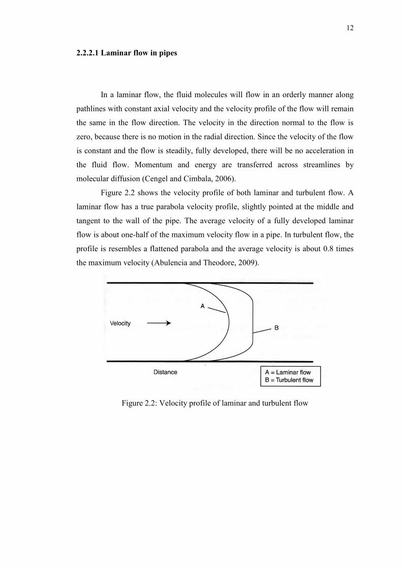
Figure 2.2 shows the velocity profile of both laminar and turbulent flow. A
laminar flow has a true parabola velocity profile, slightly pointed at the middle and
tangent to the wall of the pipe. The average velocity of a fully developed laminar
flow is about one-half of the maximum velocity flow in a pipe. In turbulent flow, the
profile is resembles a flattened parabola and the average velocity is about 0.8 times
the maximum velocity (Abulencia and Theodore, 2009).
Figure 2.2: Velocity profile of laminar and turbulent flow

13
2.2.2.2 Turbulent flow in pipes
When a flowing fluid is being obstructed by a bend, valve or even the
roughness of the pipe wall, compression would take place. When this happens, local
temperature and pressure of the fluid will increase. This will results in a turbulent
flow as the momentarily higher pressure of the fluid takes off along the path with
least resistance, converting static energy for kinetic energy (Mulley, 2004).
The random and rapid fluctuation in turbulent flows, simply known as eddies
increases the momentum and energy transfer between the fluid molecules. The
swirling eddies transfer mass, momentum and energy much more rapidly compared
to molecular diffusion, resulting in higher friction factor, heat transfer coefficient and
mass transfer coefficient (Cengel and Cimbala, 2006). The eddies impinge upon
irregularities in a pipe wall or even upon other eddies, becoming self-propagating
(Mulley, 2004).
The eddies in turbulent flow can cause fluctuation in parameter values like
velocity, temperature and pressure even when the flow is steady. Figure 2.3 shows
the fluctuation of the velocity component u with time in a turbulent flow.
Figure 2.3: Variation of the velocity component u with time at a specified location in
turbulent flow.

14
The random motion of eddies transporting the fluid particles bears a
similarity to the random motion of gas molecules, where molecules collide into each
other after travelling a certain distance and transfer momentum in the process.
Therefore, momentum transfer by eddies in a turbulent flow is similar to the
molecular momentum diffusion but in a more rapid manner. Eddy motion is more
centered and significant in the core region of a turbulent boundary layer, as it loses
its intensity close to the wall and diminished at the wall of the pipe (Cengel and
Cimbala, 2006).
2.2.3 Pressure drop and head loss
For long pipes, pressure drops are mainly due to friction (drag) caused by
molecules colliding against each other and against the pipe wall (Miesner and Leffler,
2006). In single phase flow, this friction-induced pressure drop is dominated by
Reynolds number which is a function of fluid density, fluid viscosity, fluid velocity
and pipe size. However, in multiphase flow, the pressure drop is subjected to factors
such as density, viscosity, velocity, volume fraction of each phases, and the system
pressure and temperature. These properties control the distribution of fluid interfaces,
which reflects the mechanism of momentum, heat and mass transfer among the fluids;
and thus inducing different pressure drop (Guo et al., 2005).
Pressure drop is proportional to the head loss, hL, which is the additional
height that the fluid needs to be pumped in order to overcome the frictional losses in
the pipe. These pressure losses are irreversible. If there is no friction in the flow that
is an inviscid flow, the pressure drop would be zero.
In most practice, the pressure loss for any fully developed internal flow
(laminar or turbulent) can be expressed as:
2
ρV
D
LΔP
2
avg
L f

15
where ρVavg2/2 is the dynamic pressure and f is the Darcy friction factor (Cengel and
Cimbala, 2006).
The total pressure drop of a system can be considered to consist the sum of
the following pressure drops:
To accelerate the fluid to maintain the velocity
To overcome the pipe wall friction on the fluid
To regenerate the momentum lost, and
To support the fluid in vertical pipes (Abulencia and Theodore, 2009).
There are also minor losses due to local disturbances in the flow such as
changes in cross section, elbows, valves and fittings. These minor losses are
insignificant when dealing with very long pipes or channel, because they are
relatively small compared to the major losses caused by pipe (wall) friction.
However, in very short pipes or channel, changing in direction or magnitude will
cause the average velocity of turbulent flow to alter; resulting in large eddies that
would eventually cause significant energy losses (Finnemore and Franzini, 2002).
2.3 Drag reduction
Drag reduction offers the possibility to decrease pressure drop in a pipe, as an
approach to lower the power requirement (Chhabra and Richardson, 2008). Drag
reduction is only applicable in turbulent flow and is enhanced with decreasing
viscosity and pipe diameter, together with increasing Reynolds number (Vancko,
1997).
Drag reduction can be identified as the increase of the pumpability of a fluid
when a small amount of foreign substances, such as high molecular weight polymers
is added into the flow. It is recognized through the reduction of pressure drop over
some length of pipe when the polymers fused together with the flow. There are
factors that affect the degree of drag reduction achievable in a flow, that are

16
solubility of the polymer in the continuous phase, effectiveness in dispersing the
polymer, molecular weight of the polymer and concentration of the polymer (Nelson,
2003).
2.3.1 Drag reduction agent (DRA)
Drag reduction agent (DRA) has been wide used in existing systems for its
benefit in increasing production (without mechanical modification), reduction of
operating costs such as pumping power, reduction of pipe pressure while maintaining
productivity, and boosting refinery handling (Vancko, 1997).
For the past decades, numerous drag reduction techniques have been studied
as a typical approach to save pumping power in pipelines or other transportation
channels. For example, the addition of polymers, fibers or surfactants as drag
reduction agent, the addition of suspended solid particle and the usage of riblet-
covered surface in turbulent flows.
2.3.1.1 Polymer as drag reduction agent
Ever since Toms (1948) first discovered the idea of drag reduction (DR)
when he studied the effect of polymer added into a turbulent Newtonian fluid, it was
used as a core for researchers to further discover and develop effective drag
reduction agents (DRA). Nelson (2003) mentioned that a polymer is considered as a
good DRA depending on its dispersion in the fluid, to whether the drag reducing
polymer will lead to an optimal dissolution in the flow. Therefore, ensuring the right
injection technology is used is important so as to ascertain an optimal dissolution of