intuitive tools for the design and analysis of
TRANSCRIPT

Intuitive Tools for the Design and Analysis of
Communication Payloads for Satellites
Michael R. Culver∗
Oakland University, Rochester, MI, 48309, USA
Christine Soong∗
Cornell University, Ithaca, NY, 14850, USA
Joseph D. Warner†
NASA Glenn Research Center, Cleveland, OH, 44135, USA
In an effort to make future communications satellite payload design more efficient andaccessible, two tools were created with intuitive graphical user interfaces (GUIs). The firsttool, the Visual Communication Payload design software, allows designers to graphicallydesign their payload by using a simple drag and drop action with payload componentsonto an area within the program. Information about each picked component is pulledfrom a database of common space-qualified communication components sold by commericalcompanies. Once a design is completed, various reports can be generated , such as theMaster Equipment List. The second tool, RF Link Budget Calculator software, is a linkbudget calculator designed specifically for ease of use. Other features of this tool includebeing able to access a database of NASA ground based apertures for near Earth andDeep Space communication, the Tracking and Data Relay Satellite System (TDRSS) baseapertures, and information about the solar system relevant to link budget calculations. Thelink budget tool allows for over 50 different combinations of user inputs, eliminating theneed for multiple spreadsheets and the errors associated with wrong inputs. Both of theaforementioned tools increase the productivity of space communication systems designers,and have the colloquial latitude to allow non-communication experts to design preliminarycommunication payloads.
Nomenclature
CLI Command-Line InterfacedB Decibel: logarithmic measure of a ratiodBW Decibel relative to 1 WattDSN Deep Space NetworkDSS Deep Space StationGUI Graphical User InterfaceIDE Integrated Development EnvironmentNASA National Aeronautics and Space AdministrationRF Radio frequencyTDRSS Tracking and Data Relay Satellite System
I. Introduction
Space communications system design can be tedious and complicated when using unoptimized designtools. This is certainly the case with previous link budget calculator tools, which rely on complicatedand contrived spreadsheet operations. In such operations, information is easily lost and/or miscalculatedbecause of the lack of scalability of the spreadsheet formulas. This, in turn, makes communication payload
∗This work was completed over a summer internship at NASA GRC, SCaN, 21000 Brookpark Rd., Student AIAA member.†Senior Physicist, Aerospace Communications Systems Branch, 21000 Brookpark Rd.
1 of 9
American Institute of Aeronautics and Astronautics

design hard to learn for a newcomer to the field. After a link budget is determined for a NASA mission,physical communication payload components must be picked to create and close this link. This step ofthe process involves looking up each company’s product and comparing the product’s characteristics withthe requirements, which takes a lot of time. Creating a more intuitive user interface for calculating thelink budget and picking payload components can reduce any possible error with calculations, obtainingcomponent information, and increase efficiency for experienced communications engineers.
I.A. Background
In the past, other link budget tools have been created to aid the user in calculating a link budget. Theyhave evolved from CLI programs, to formulae across spreadsheets, to primitive GUI programs. For example,an older optical link budget calculator tool created by Emily Kukura previously used command line queriesas shown in Figure 1.
Figure 1. Command Line Link Budget Program
Even more, a satellite communications toolbox has been created by Mathworks to also help calculatebasic characteristics for a satellite link. It allows a user to use predefined functional blocks to create graphsfor carrier to noise power. However, using this toolbox involves substantial monetary purchase of MATLABsoftware and time to become acquainted with the MATLAB software and programming language.
A link budget is a first step for communications payload designers and potential users to determineif a wireless transmitter and receiver can “close” a link, meaning if a wireless signal has enough powerat the receiving end such that its information is retained and readable.5 The link budget is a way fordesigners and users to obtain a prelimary understanding of the dynamics which will be involved in draftingthe communications systems of a mission.
Naively, one could say a link budget equation appears:
Received Power = Transmitted Power +Gains+Received Area− Losses (1)
Eq. (1) is a simplistic way of showing the idea behind calculating a link budget. Received and TransmittedPower is measured in dBW , while Gains, Received Area, and Losses are measured in dB.
This equation becomes far more complex when one considers how to calculate each term. For example,how one determines the gain of DSS 27 based on its inclination, frequency, and surrounding wind froma cursory reading of the DSN Telecommunications Link Design Handbook easily demonstrates this.3 So,the difficulty/complexity in these calculations is the primary motivation for the creation of a user-friendlyprogram which aides in link budget calculation.
Once the link budget is finalized, a rough sketch of the generic components needed for the payload ismade to obtain an estimate of the power and mass to meet the requirements of the NASA mission. Figure 2shows a generic communication payload for a single fault relay communication system. The switches switchin redundant components if the primary one fails. The diplexers in Figure 2 allows the same antenna totransmit on one frequency band and receive on a different one. The use of up and down converters allow acommunication relay to receive and transmit signals between two different communication sources.
2 of 9
American Institute of Aeronautics and Astronautics
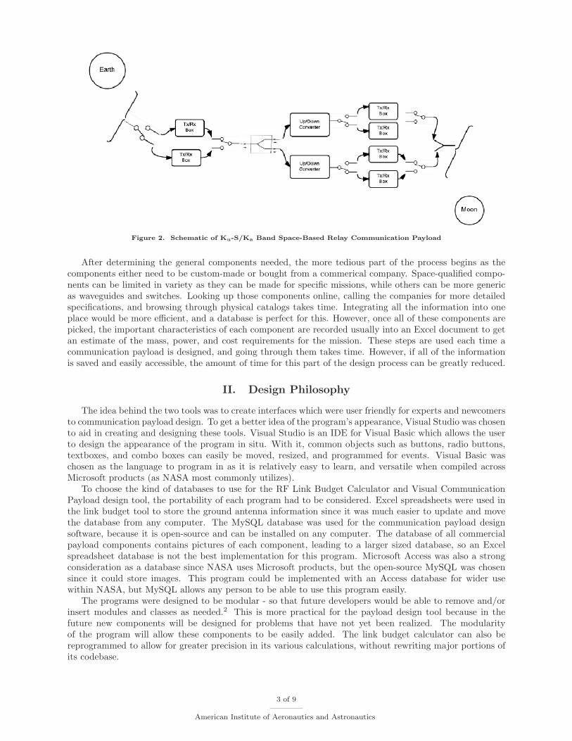
Figure 2. Schematic of Ku-S/Ka Band Space-Based Relay Communication Payload
After determining the general components needed, the more tedious part of the process begins as thecomponents either need to be custom-made or bought from a commerical company. Space-qualified compo-nents can be limited in variety as they can be made for specific missions, while others can be more genericas waveguides and switches. Looking up those components online, calling the companies for more detailedspecifications, and browsing through physical catalogs takes time. Integrating all the information into oneplace would be more efficient, and a database is perfect for this. However, once all of these components arepicked, the important characteristics of each component are recorded usually into an Excel document to getan estimate of the mass, power, and cost requirements for the mission. These steps are used each time acommunication payload is designed, and going through them takes time. However, if all of the informationis saved and easily accessible, the amount of time for this part of the design process can be greatly reduced.
II. Design Philosophy
The idea behind the two tools was to create interfaces which were user friendly for experts and newcomersto communication payload design. To get a better idea of the program’s appearance, Visual Studio was chosento aid in creating and designing these tools. Visual Studio is an IDE for Visual Basic which allows the userto design the appearance of the program in situ. With it, common objects such as buttons, radio buttons,textboxes, and combo boxes can easily be moved, resized, and programmed for events. Visual Basic waschosen as the language to program in as it is relatively easy to learn, and versatile when compiled acrossMicrosoft products (as NASA most commonly utilizes).
To choose the kind of databases to use for the RF Link Budget Calculator and Visual CommunicationPayload design tool, the portability of each program had to be considered. Excel spreadsheets were used inthe link budget tool to store the ground antenna information since it was much easier to update and movethe database from any computer. The MySQL database was used for the communication payload designsoftware, because it is open-source and can be installed on any computer. The database of all commercialpayload components contains pictures of each component, leading to a larger sized database, so an Excelspreadsheet database is not the best implementation for this program. Microsoft Access was also a strongconsideration as a database since NASA uses Microsoft products, but the open-source MySQL was chosensince it could store images. This program could be implemented with an Access database for wider usewithin NASA, but MySQL allows any person to be able to use this program easily.
The programs were designed to be modular - so that future developers would be able to remove and/orinsert modules and classes as needed.2 This is more practical for the payload design tool because in thefuture new components will be designed for problems that have not yet been realized. The modularityof the program will allow these components to be easily added. The link budget calculator can also bereprogrammed to allow for greater precision in its various calculations, without rewriting major portions ofits codebase.
3 of 9
American Institute of Aeronautics and Astronautics

III. Design Implementation
Stepping through the process, for the Communication Payload Design Tool, there were several interfacesthat needed to be created: main interface, inputting component details, and generating the report form.The main interface is shown in Figure 3.
Figure 3. Main interface of Communication Payload Design Tool
The left panel allows the user to create the components onto the white design area on the right. Genericcomponents can be picked on the communication payload design tool and arranged in the certain configura-tion. As each component is added to the design area, the user can pick from a list of commercially availablecomponents from a database that the database automatically retrieves as shown in Figure 4.
Figure 4. List is pulled from a database
The database stores all relevant information for each component such as mass, power, operating tem-perature range, and dimensions as seen in the middle panel in Figure 3. When someone right clicks ontothe component, it gives the user options to delete, edit, or view the component’s information, also shown inFigure 4.
The database skeleton was set up and populated with a few example components as shown in Figure 5:
4 of 9
American Institute of Aeronautics and Astronautics

Figure 5. Sample Component for Parabolic Antennas
An overview of the features of the Communication Payload Design Tool is located in Appendix A.Likewise, for the Link Budget Calculator Tool, several interfaces were needed: a main interface, a system
noise interface, a solar system body distance selection interface, and a antenna database interface.The main interface is shown in Figure 6.
Figure 6. Main interface of link budget calculator
The four colored boxes each denote a general domain of discussion for what will be entered/returned.The leftmost is for transmitting information, the next for range information, then for receiving information,and finally for data information. In each box there are some fields which are open for input, and someblocked to prevent error (depending upon which options are chosen for a particular calculation). Prior torunning a calculation, each enabled input is checked to be sure it is numeric and in the correct range.
To allow the user the option of calculating system noise temperature directly, an interface for calculatingthe system noise temperature was added as seen in Figure 7.
Figure 7. System noise temperature calculator interface
5 of 9
American Institute of Aeronautics and Astronautics

One can see the various different parameters which can be taken into account when calculating systemnoise temperature. The program allows the user to calculate the system noise temperature three ways: en-tering the system noise temperature directly, entering the receiver noise temperature along with backgroundsand antenna temperatures, or by entering the backgrounds and antenna temperatures above and the lownoise amplifier gain and noise temperature, and the losses after the LNA.
The solar system body distance calculator is shown in Figure 8.
Figure 8. Solar system body distance calculator interface
This interface allows a user to select either a close, medium, or far approach from a solar body and obtaina range without leaving the program, as the data is preprogrammed in.
Finally, the antenna database interface for DSN sites is shown in Figure 9. It allows the user to selectthe site, the frequency band used, the antenna, the elevation angle, and the cumulative distribution.
Figure 9. Antenna database interface
The antenna database interface greatly simplifies the process of obtaining data on a particular antennasuch as what power, frequency, and gain the antenna is able to transmit/receive. Usually, one must leafthrough a telecommunications design handbook to obtain this information, but the program was designedto automatically integrate all of the antenna data from the Excel database into this interface.
6 of 9
American Institute of Aeronautics and Astronautics

IV. Results
After using the link budget calculator tool to calculate a link, the results of each parameter that goesinto calculating the link can be saved as an Excel or pdf file. A sample of the pdf output is shown in Figure10.
Figure 10. A portion of the results given by the link budget calculator’s pdf output
The same goes with the Visual Communication Payload Design Tool:
Figure 11. Project Description of Design Report
The Visual Communication Payload program will generate a report that always consists of the projectdescription cover page as shown in Figure 11.
7 of 9
American Institute of Aeronautics and Astronautics

Figure 12. MEL/PEL Equipment List of Design Report
In addition, the second page of the report contains a table of the relevant characteristics for each payloadcomponent for a mission, which is often the mass and power equipment list as shown in Figure 12.
Figure 13. Component Description of Design Report
Then, the rest of the report will contain detailed descriptions of each component such as in Figure 13.Each page is one component, and within each page, a picture is in the top right corner while the relevantcharacteristics are in the top left table. Then the rest of the compoents characteristics are in the main table.
V. Conclusions
The creation of these two tools will have shortened the pre-design process for a NASA by performingall the functions needed for a designer as well as making it easy to use for the designer. The link budgetcalculator tool calculates scenarios with different parameters such as the link between Earth and weather-observing satellites or transmitting images from rovers on the Jupiter moon, Io, back to Earth. Then thecalculator saves these different scenarios in a way so they are easier to compare while integrating relevant
8 of 9
American Institute of Aeronautics and Astronautics

information into the program. Having all the information in one program allows the link budget analysis togo more smoothly instead of having to look up the radius of a ground station antenna or distance between twoplanets. The communication payload tool will shorten the the process of designing the payload by integratingall the information of commercial components in one place, instead of looking up each and every componentthrough separate catalogs. Also, it allows the user to create a visual representation of their design with anintuitive main interface. These two tools are or will be used for NASA missions in communication payloaddesign, and these tools in the future can be expanded on to include more features such as connecting the linkbudget calculator tool together with the communication payload design software to see what componentsare available to meet the requirements of the specific mission.
Appendix
Appendix A
By: Christine SoongObjective: Support rapid payload design for user by having all relevant information of components in one central location
Option for user to delete, edit, and view component details
General Features:� Developed through VB.Net on Visual Studio 2012� Connects to MySQL database of component information� Graphical User Interface:
� Create as many components as needed� Arrange components to user’s configuration� Resize drawing area & individual components� Contains premade configuration of basic payload
designs� Output:
� Export details of all components onto Excel & Text File
� Exports screenshot of current configuration� Can save current configuration & reopen later
Commercial Component Option:
� Allows user to select from a list of commercial parts stored in MySQL database
� Once a component is selected, program will retrieve all details of the component from the database & automatically fill it in
User-Defined Component Option:
Allows user to define their own component and fill in the characteristics associated with it
MySQL Database:
� Contains tables of components & their details: antennas, diplexers, gimbals, receiver, transmitters, transceivers, up/down converters
� Can enter component information anytime & program will automatically retrieve the list
� Can associate an image for a specific component
Visual Communication PayloadDesign Software
Acknowledgments
We would like thank Dr. Kul B. Bhasin, Sr. Space Communications Architect at NASA Glenn ResearchCenter, for his support with our projects. We would also like to thank the SCaN Summer Intern Project forproviding us with the opportunity to perform this work.
References
1Bhasin, K.B., Warner, J.D., and Anderson, L.M., ”Lunar Communication Terminals for NASA Exploration Missions:Needs, Operations Concepts and Architectures”, NASA Glenn Research Center, Cleveland, OH, June, 2008
2Dommelen, L., ”Modular Programming”, Florida State University3Many authors, ”DSN Telecommunications Link Design Handbook”, NASA Jet Propulsion Laboratory, 20134Parmar, K. and Dafda, A., ”Design of Satellite Communications Toolbox for MATLAB”, International Journal of Elec-
trical and Computer Engineering, Gujarat Technological University, 20125Tsai, M., ”Link Budget”, National Taiwan University, 2011
9 of 9
American Institute of Aeronautics and Astronautics