introduction to verilog hdl - fke.utm.myl2: verilog hdl 2012/2013-1 • verilog describes a digital...
TRANSCRIPT
L2: VERILOG HDL 2012/2013-1
INTRODUCTION TOVERILOG HDL
CAD for ASIC Design 1
L2: VERILOG HDL 2012/2013-1
OVERVIEW
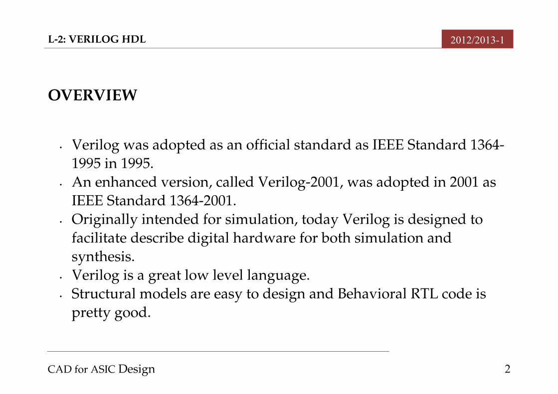
• Verilog was adopted as an official standard as IEEE Standard 13641995 in 1995.
• An enhanced version, called Verilog2001, was adopted in 2001 as IEEE Standard 13642001.
• Originally intended for simulation, today Verilog is designed to facilitate describe digital hardware for both simulation and synthesis.
• Verilog is a great low level language. • Structural models are easy to design and Behavioral RTL code is
pretty good.
CAD for ASIC Design 2
L2: VERILOG HDL 2012/2013-1
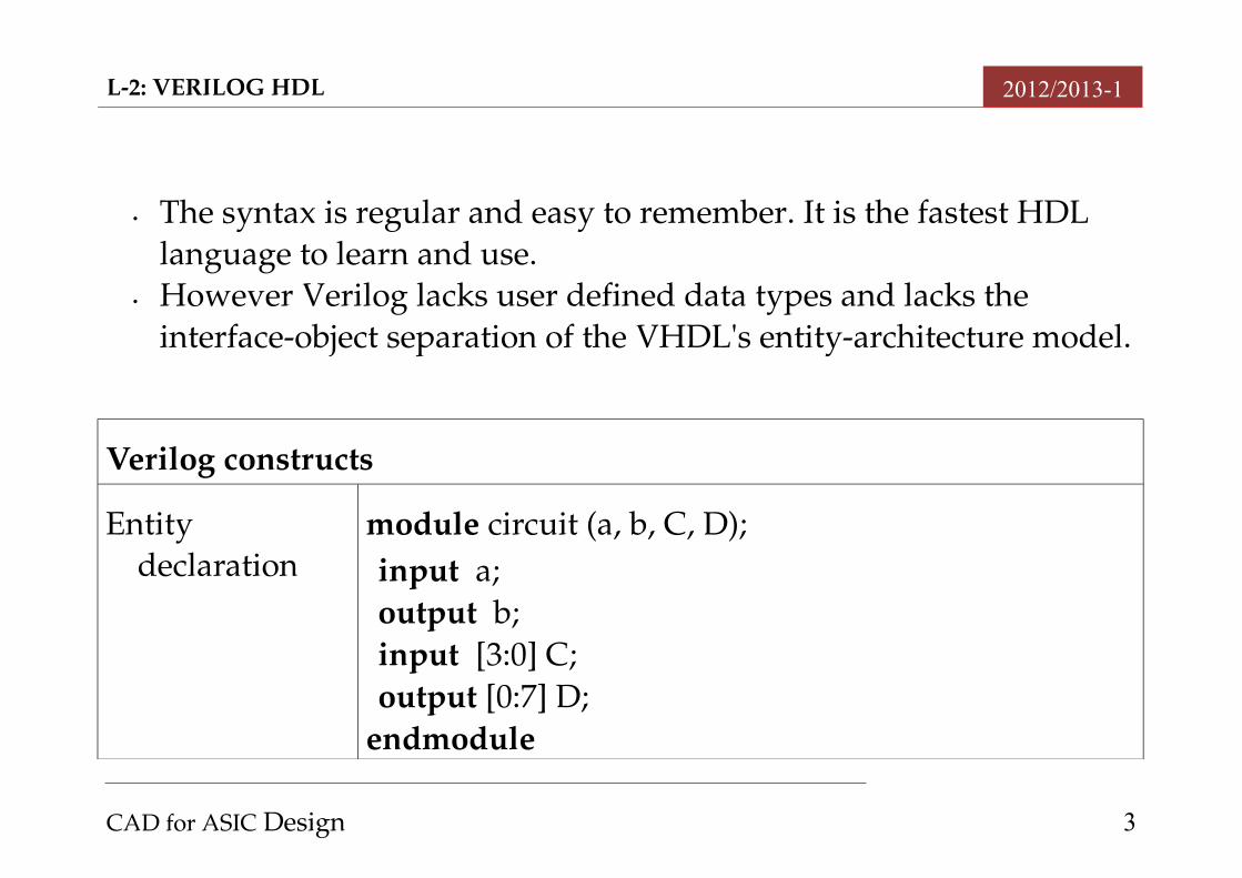
• The syntax is regular and easy to remember. It is the fastest HDL language to learn and use.
• However Verilog lacks user defined data types and lacks the interfaceobject separation of the VHDL's entityarchitecture model.
Verilog constructs
Entity declaration
module circuit (a, b, C, D);input a;output b;input [3:0] C;output [0:7] D;
endmodule
CAD for ASIC Design 3
L2: VERILOG HDL 2012/2013-1
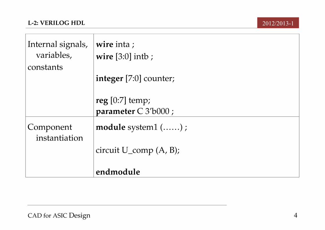
Internal signals, variables,
constants
wire inta ;wire [3:0] intb ;
integer [7:0] counter;
reg [0:7] temp;parameter C 3’b000 ;
Component instantiation
module system1 (……) ;
circuit U_comp (A, B);
endmodule
CAD for ASIC Design 4
L2: VERILOG HDL 2012/2013-1
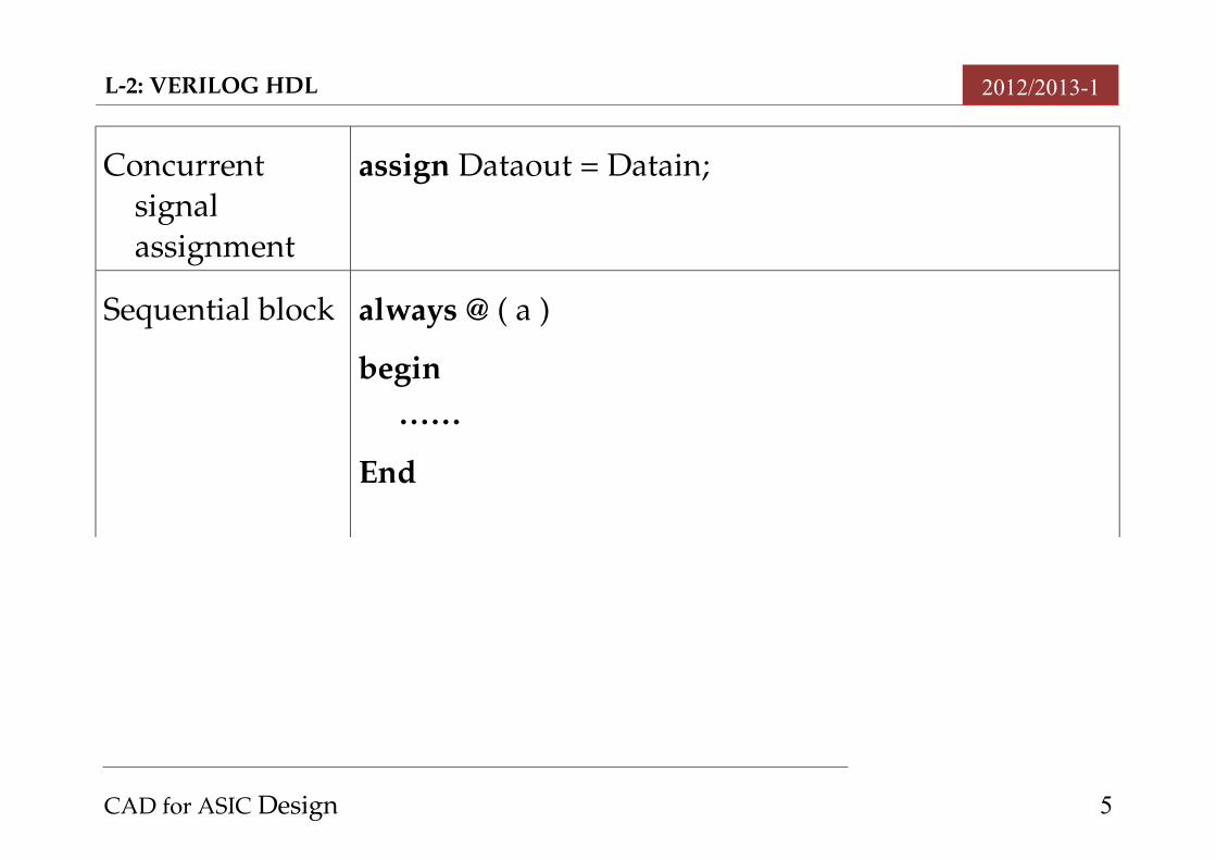
Concurrent signal assignment
assign Dataout = Datain;
Sequential block always @ ( a )
begin ……
End
CAD for ASIC Design 5
L2: VERILOG HDL 2012/2013-1
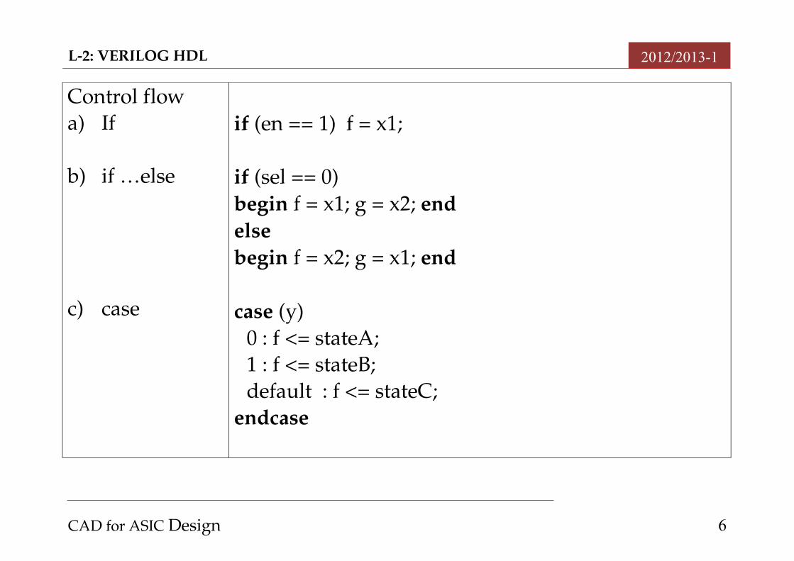
Control flowa) If
b) if …else
c) case
if (en == 1) f = x1;
if (sel == 0) begin f = x1; g = x2; endelsebegin f = x2; g = x1; end
case (y)0 : f <= stateA;1 : f <= stateB;default : f <= stateC;
endcase
CAD for ASIC Design 6
L2: VERILOG HDL 2012/2013-1
BASICS OF VERILOG
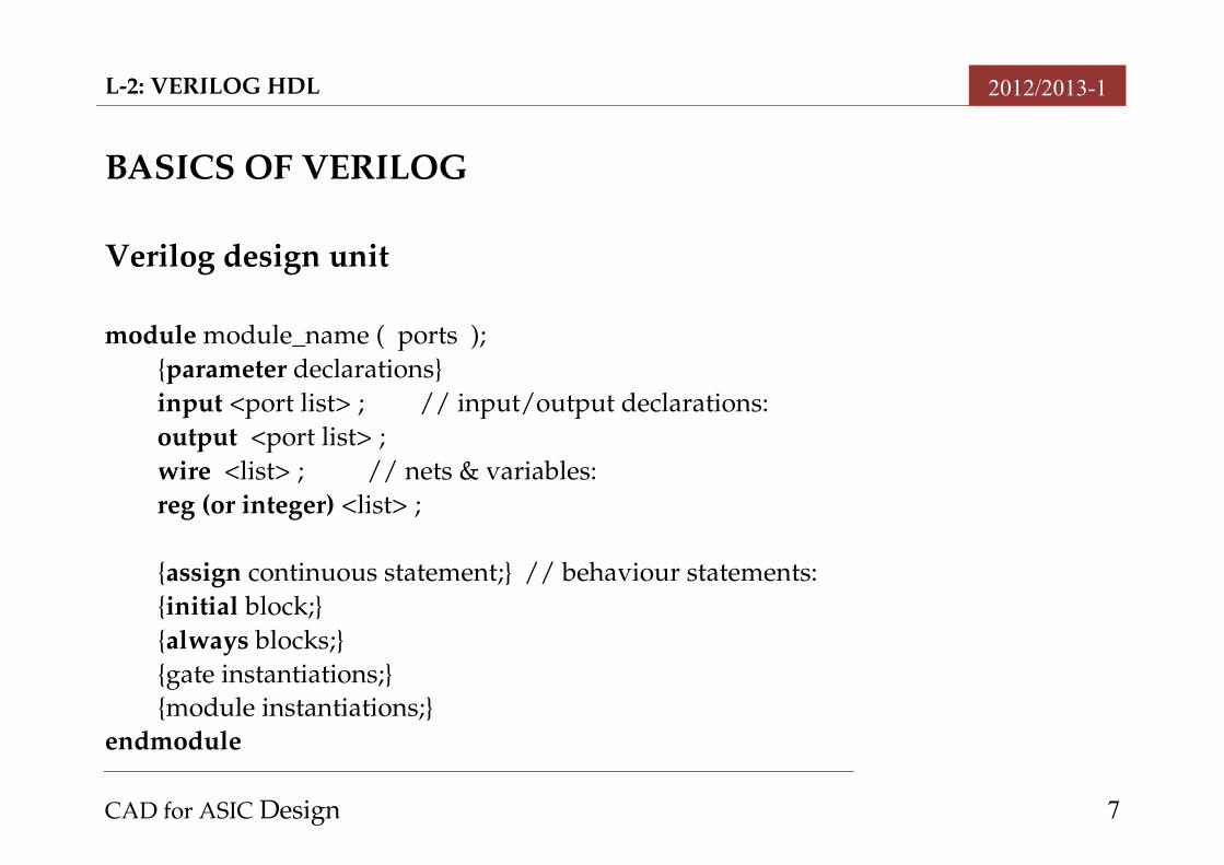
Verilog design unit
module module_name ( ports );{parameter declarations}input <port list> ; // input/output declarations:output <port list> ;wire <list> ; // nets & variables:reg (or integer) <list> ;
{assign continuous statement;} // behaviour statements:{initial block;} {always blocks;}{gate instantiations;}{module instantiations;}
endmodule
CAD for ASIC Design 7
L2: VERILOG HDL 2012/2013-1
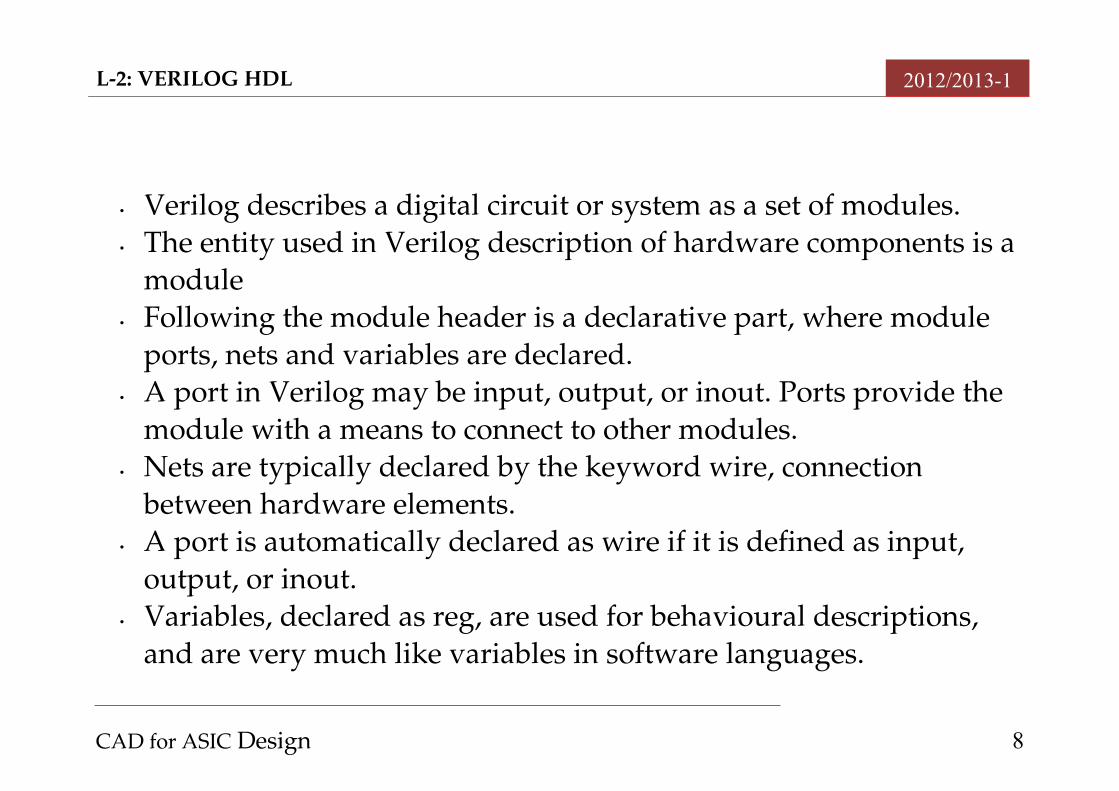
• Verilog describes a digital circuit or system as a set of modules. • The entity used in Verilog description of hardware components is a
module• Following the module header is a declarative part, where module
ports, nets and variables are declared. • A port in Verilog may be input, output, or inout. Ports provide the
module with a means to connect to other modules. • Nets are typically declared by the keyword wire, connection
between hardware elements. • A port is automatically declared as wire if it is defined as input,
output, or inout. • Variables, declared as reg, are used for behavioural descriptions,
and are very much like variables in software languages.
CAD for ASIC Design 8
L2: VERILOG HDL 2012/2013-1
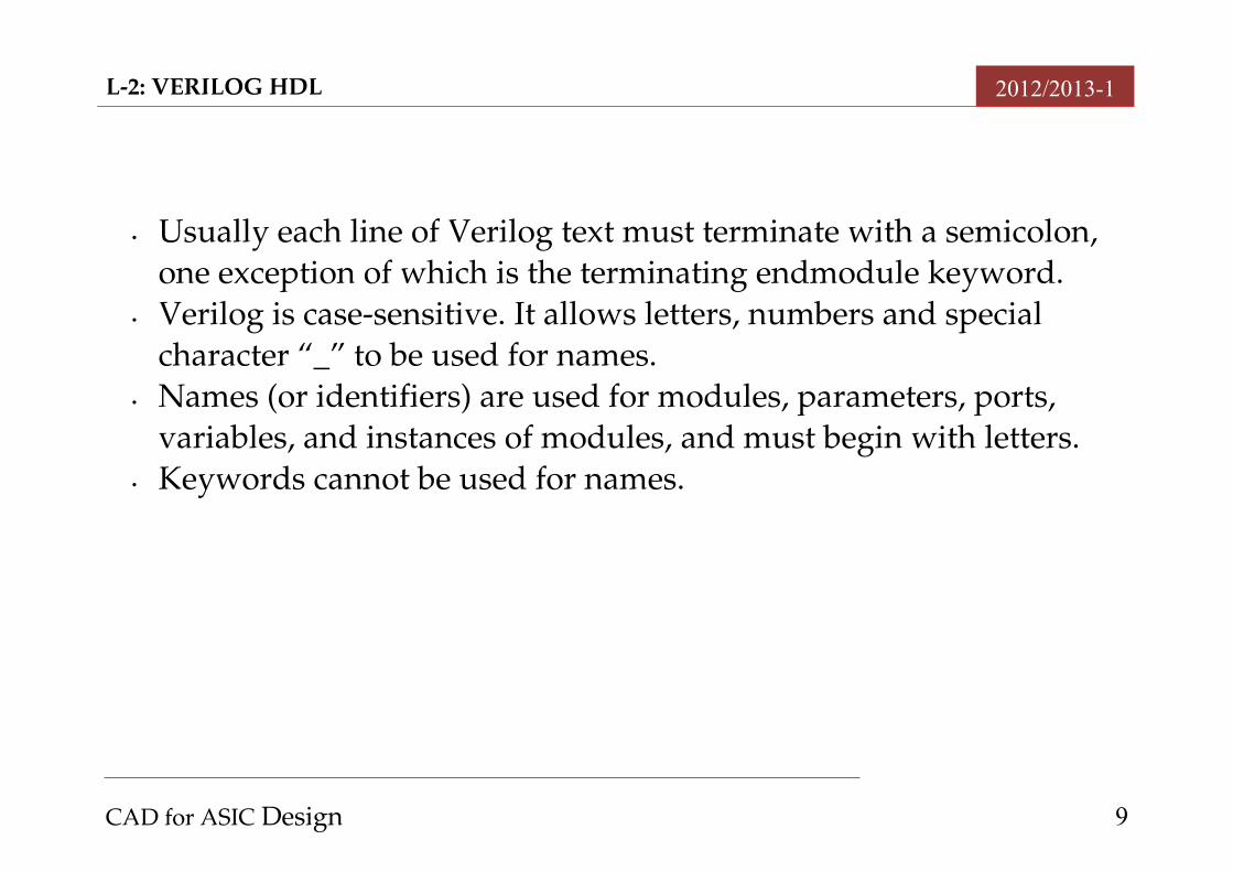
• Usually each line of Verilog text must terminate with a semicolon, one exception of which is the terminating endmodule keyword.
• Verilog is casesensitive. It allows letters, numbers and special character “_” to be used for names.
• Names (or identifiers) are used for modules, parameters, ports, variables, and instances of modules, and must begin with letters.
• Keywords cannot be used for names.
CAD for ASIC Design 9
L2: VERILOG HDL 2012/2013-1
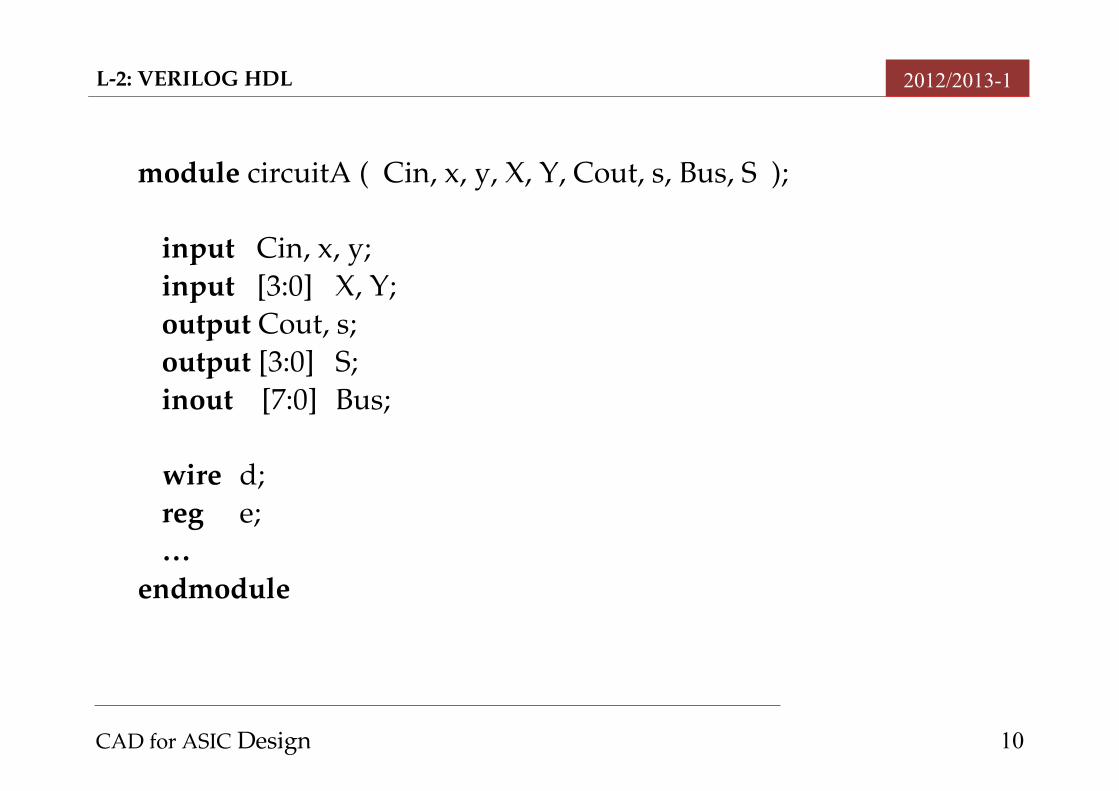
module circuitA ( Cin, x, y, X, Y, Cout, s, Bus, S );
input Cin, x, y;input [3:0] X, Y;output Cout, s;output [3:0] S;inout [7:0] Bus;
wire d;reg e;…
endmodule
CAD for ASIC Design 10
L2: VERILOG HDL 2012/2013-1
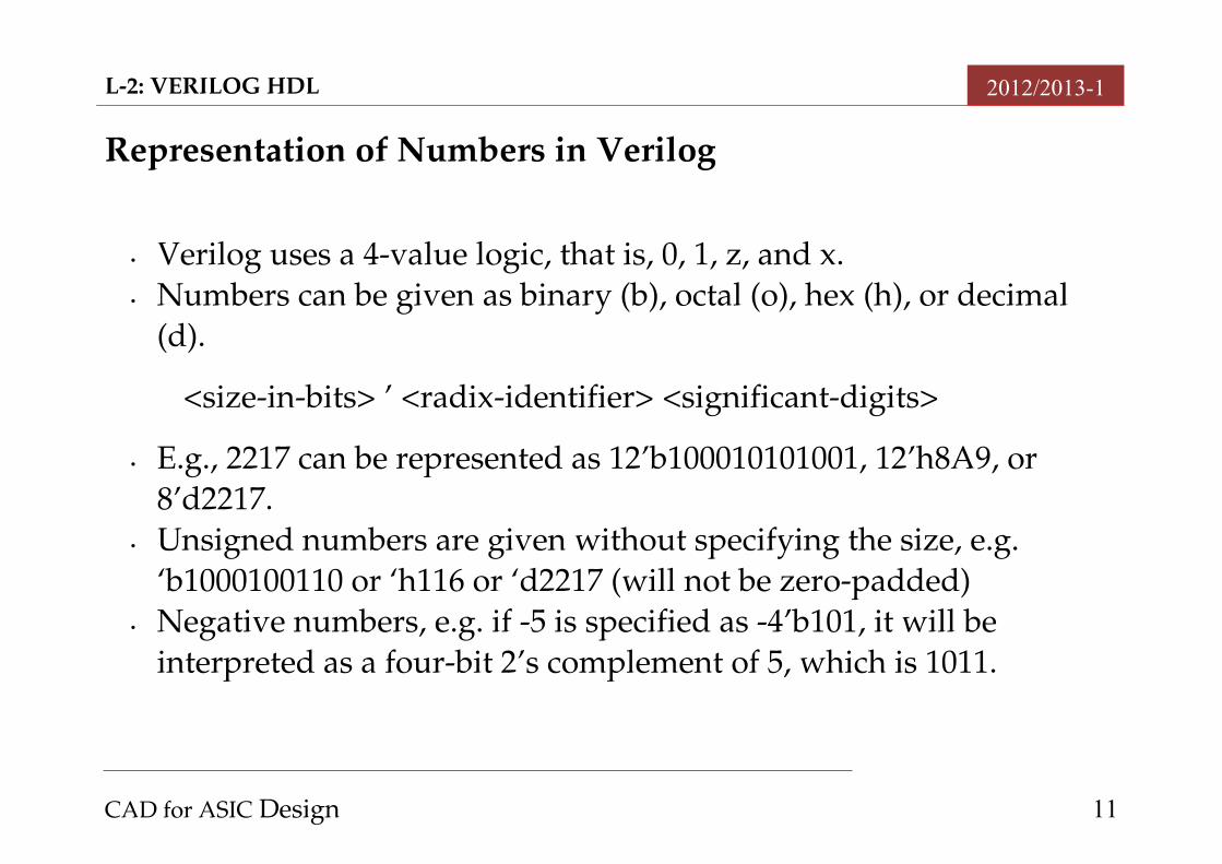
Representation of Numbers in Verilog
• Verilog uses a 4value logic, that is, 0, 1, z, and x. • Numbers can be given as binary (b), octal (o), hex (h), or decimal
(d).
<sizeinbits> ’ <radixidentifier> <significantdigits>
• E.g., 2217 can be represented as 12’b100010101001, 12’h8A9, or 8’d2217.
• Unsigned numbers are given without specifying the size, e.g. ‘b1000100110 or ‘h116 or ‘d2217 (will not be zeropadded)
• Negative numbers, e.g. if 5 is specified as 4’b101, it will be interpreted as a fourbit 2’s complement of 5, which is 1011.
CAD for ASIC Design 11
L2: VERILOG HDL 2012/2013-1
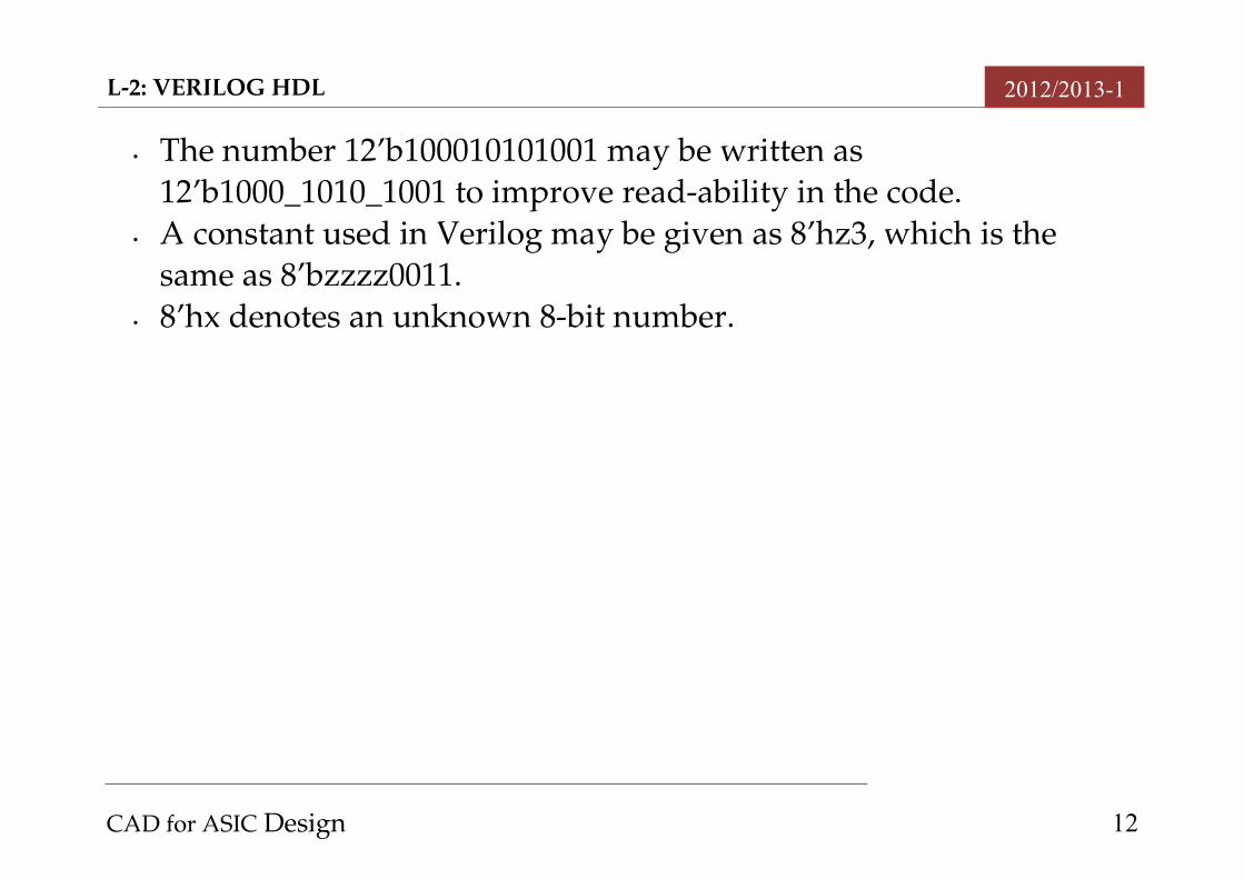
• The number 12’b100010101001 may be written as 12’b1000_1010_1001 to improve readability in the code.
• A constant used in Verilog may be given as 8’hz3, which is the same as 8’bzzzz0011.
• 8’hx denotes an unknown 8bit number.
CAD for ASIC Design 12
L2: VERILOG HDL 2012/2013-1
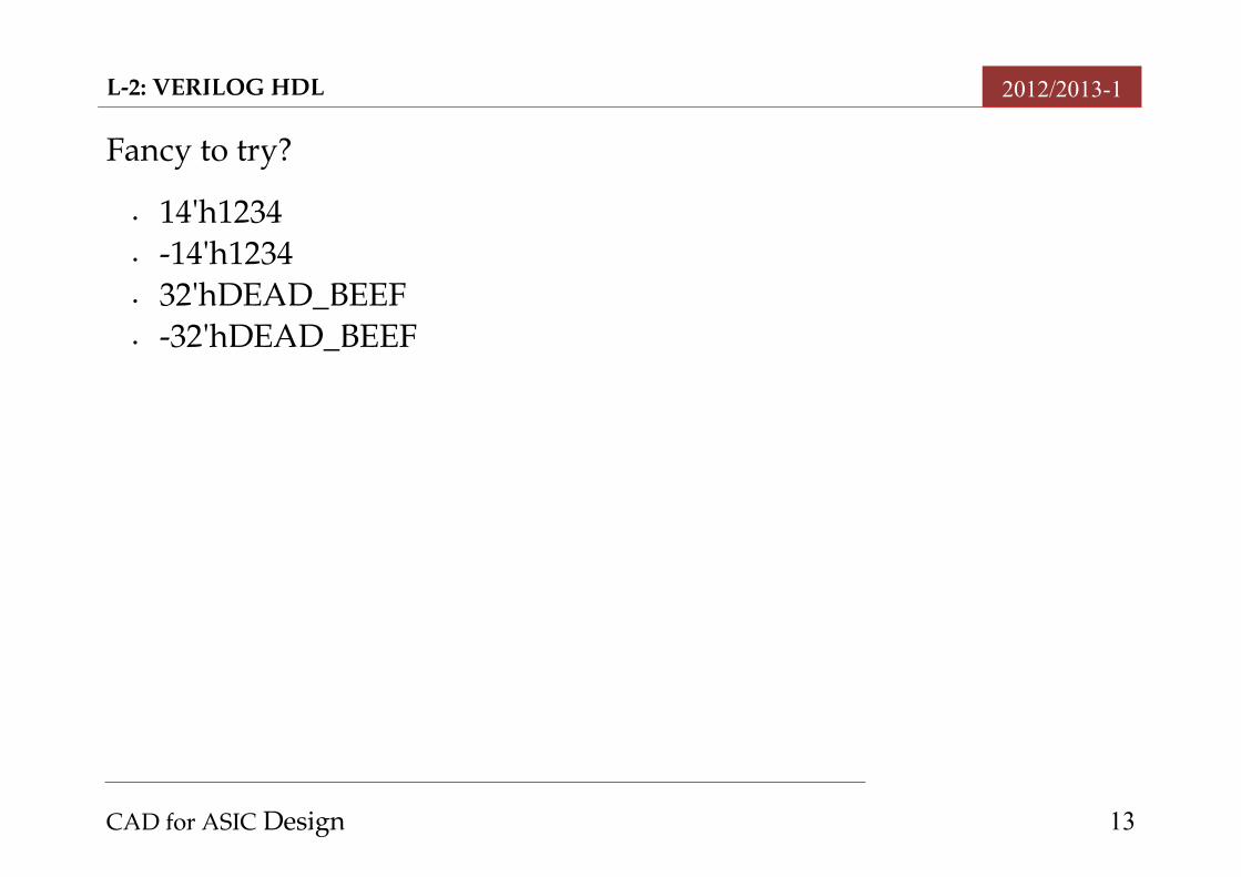
Fancy to try?
• 14'h1234• 14'h1234• 32'hDEAD_BEEF• 32'hDEAD_BEEF
CAD for ASIC Design 13
L2: VERILOG HDL 2012/2013-1
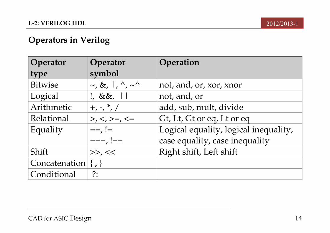
Operators in Verilog
Operator type
Operator symbol
Operation
Bitwise ~, &, |, ^, ~^ not, and, or, xor, xnorLogical !, &&, || not, and, orArithmetic +, , *, / add, sub, mult, divideRelational >, <, >=, <= Gt, Lt, Gt or eq, Lt or eqEquality ==, !=
===, !==Logical equality, logical inequality, case equality, case inequality
Shift >>, << Right shift, Left shiftConcatenation { , }Conditional ?:
CAD for ASIC Design 14
L2: VERILOG HDL 2012/2013-1
Consider that A, B, and C to be operands, either vectors or scalar (1bit).
• The bitwise operator produce the same number of bits as the operands. E.g, A = a1a0, B = b1b0, C = c1c0, then A|B results in c1=a1|b1 and c0 = a0|b0.
• The logical operator generates a onebit result. Used in conditional statements.
o A||B results in 1 unless both A and B are zeroso A && B will produce a result of 1 if both A and B are nonzeros. o !A gives a 1 if all its bits are 0, otherwise it results in a 1.
• The relational operator outputs a 1 or 0 based on the (specified) comparison of A and B.
• The shift operators perform logical 1bit shifts to the right or left, with zeros shifted in.
CAD for ASIC Design 15
L2: VERILOG HDL 2012/2013-1
• In the case of the conditional operator, the operation A?B:C produce a result that is equal to B if A evaluates to 1, otherwise the result is C.
• The precedence of Verilog operators is similar to that found in arithmetic and Boolean algebra.
CAD for ASIC Design 16
L2: VERILOG HDL 2012/2013-1
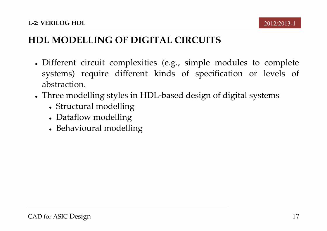
HDL MODELLING OF DIGITAL CIRCUITS
Different circuit complexities (e.g., simple modules to complete systems) require different kinds of specification or levels of abstraction.
Three modelling styles in HDLbased design of digital systems Structural modelling Dataflow modelling Behavioural modelling
CAD for ASIC Design 17
L2: VERILOG HDL 2012/2013-1
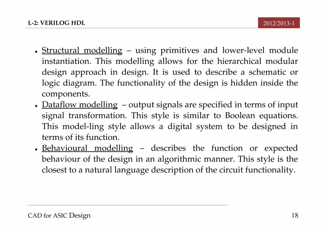
Structural modelling – using primitives and lowerlevel module instantiation. This modelling allows for the hierarchical modular design approach in design. It is used to describe a schematic or logic diagram. The functionality of the design is hidden inside the components.
Dataflow modelling – output signals are specified in terms of input signal transformation. This style is similar to Boolean equations. This modelling style allows a digital system to be designed in terms of its function.
Behavioural modelling – describes the function or expected behaviour of the design in an algorithmic manner. This style is the closest to a natural language description of the circuit functionality.
CAD for ASIC Design 18
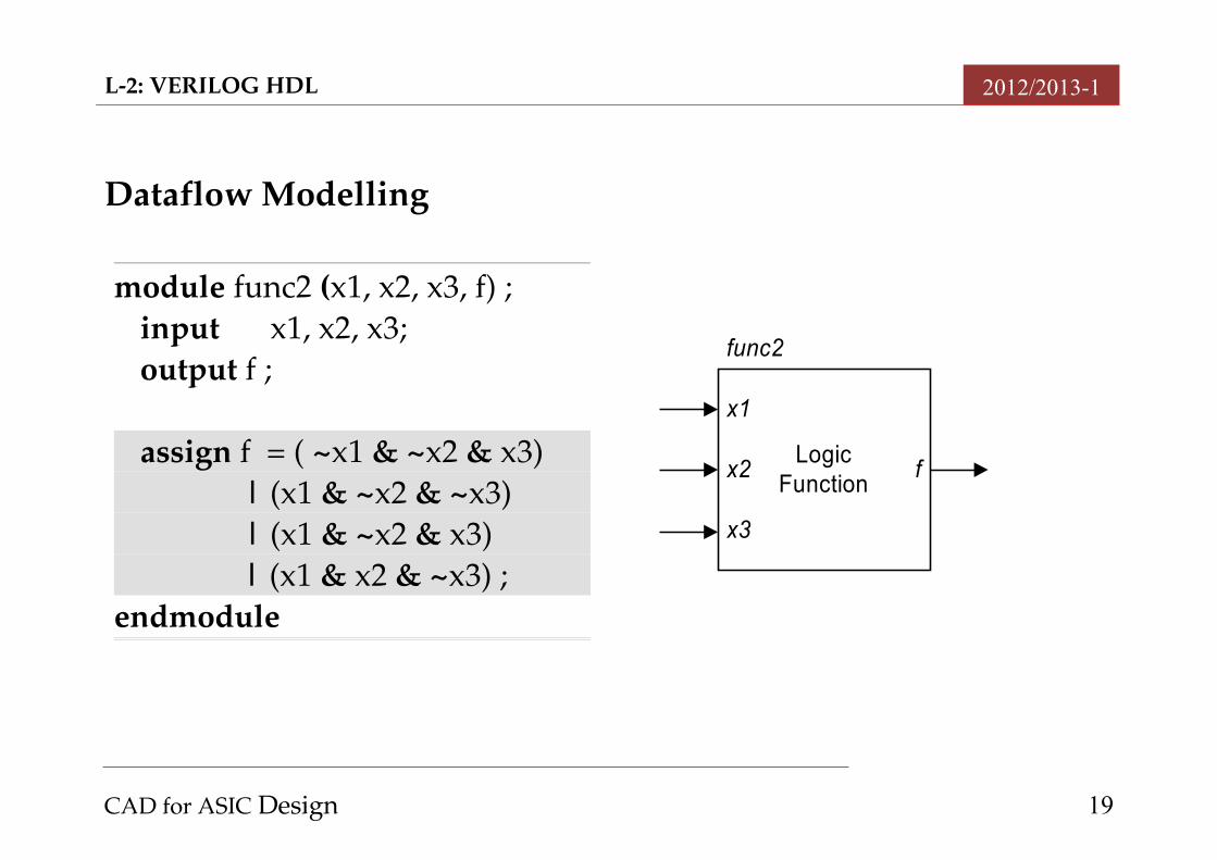
LogicFunction
x1
x2
x3
f
func2
L2: VERILOG HDL 2012/2013-1
Dataflow Modelling
CAD for ASIC Design 19
module func2 (x1, x2, x3, f) ;input x1, x2, x3;output f ;
assign f = ( ~x1 & ~x2 & x3) | (x1 & ~x2 & ~x3) | (x1 & ~x2 & x3)
| (x1 & x2 & ~x3) ;endmodule
L2: VERILOG HDL 2012/2013-1
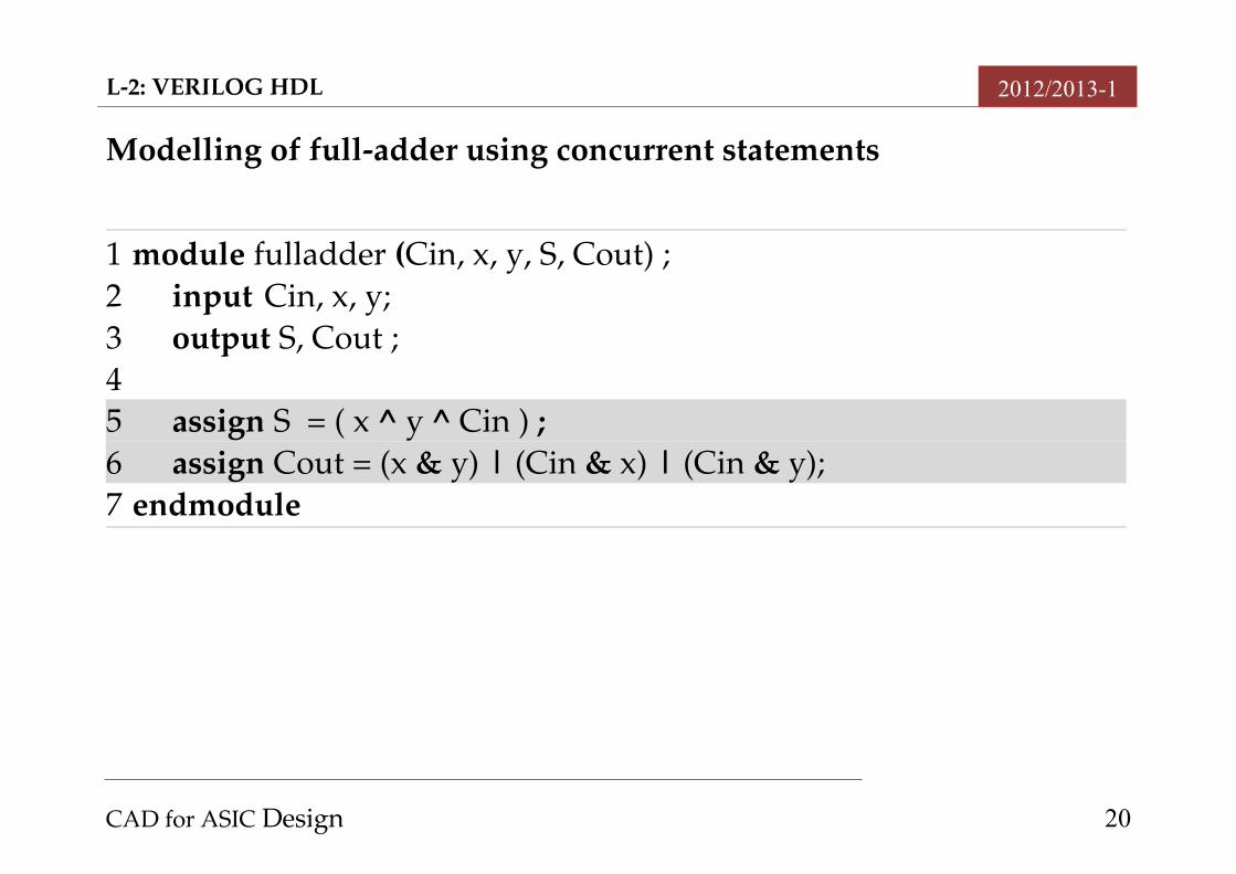
Modelling of fulladder using concurrent statements
CAD for ASIC Design 20
1 module fulladder (Cin, x, y, S, Cout) ;2 input Cin, x, y;3 output S, Cout ;45 assign S = ( x ^ y ^ Cin ) ;6 assign Cout = (x & y) | (Cin & x) | (Cin & y);7 endmodule
L2: VERILOG HDL 2012/2013-1
Notes on Concurrent/ Continuous signal assignment statements
In Verilog, concurrent assignment statements are called continuous assignment statements.
Lines 5 and 6 in the above Verilog code are continuous assignment statements, by the fact that they begin with the assign keyword.
They are executed concurrently, and the line order is not important. Besides concurrent statements, there are also sequential (in VHDL
jargon) or procedural (in Verilog jargon) statements. Differing from concurrent statements, sequential statements are
evaluated in the order in which they appear in the code. Verilog syntax require them to be in an always block.
CAD for ASIC Design 21
L2: VERILOG HDL 2012/2013-1
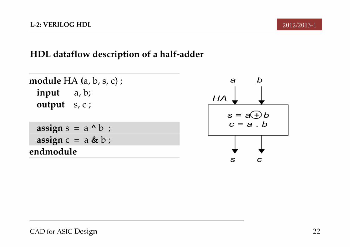
HDL dataflow description of a halfadder
CAD for ASIC Design 22
s = a + bc = a . b
HA
a b
s c
module HA (a, b, s, c) ;input a, b;output s, c ;
assign s = a ^ b ;assign c = a & b ;
endmodule
L2: VERILOG HDL 2012/2013-1
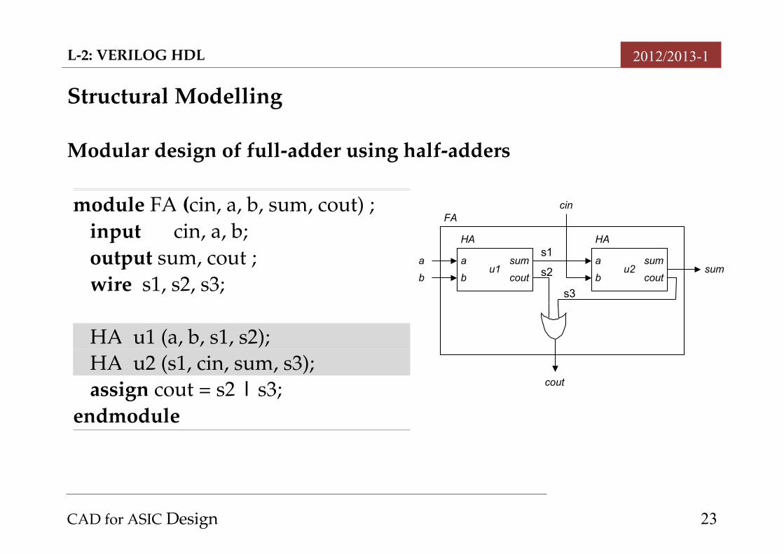
Structural Modelling
Modular design of fulladder using halfadders
CAD for ASIC Design 23
module FA (cin, a, b, sum, cout) ;input cin, a, b;output sum, cout ;wire s1, s2, s3;
HA u1 (a, b, s1, s2);HA u2 (s1, cin, sum, s3);assign cout = s2 | s3;
endmodule
u1
HA
cout
a
b
sumu2
HA
cout
a
b
suma
cin
cout
sumb
FA
s1
s2
s3
L2: VERILOG HDL 2012/2013-1
In Verilog structural modelling, module instantiation is used. The instantiation statement associates the signals in the instantiated
module (HA, in this case) with the ports of the design unit (FA in this case).
Here, positional association is applied, where each signal in the instantiation statement is mapped by position to the corresponding signal in the module.
CAD for ASIC Design 24
L2: VERILOG HDL 2012/2013-1
Behavioural Modelling
At higher levels of design abstraction, a digital module is often modelled behaviourally,
The function or operation of the module is described in an algorithmic manner.
The HDL code will contain statements that are executed sequentially in a predefined order (or procedure).
The order of the sequential (or procedural) statements in the HDL code is important and may affect the semantics of the code.
CAD for ASIC Design 25
L2: VERILOG HDL 2012/2013-1
Behavioural Modelling in Verilog
Behavioural modelling in Verilog uses constructs similar to C language constructs.
Sequential statements, like ifelse and case statements, are called procedural statements.
Procedural statements be contained inside a construct called an always block
An always block execute sequentially in the order they are listed in the source code.
The @ symbol is called the event control operator. The part after the @ symbol, is the event control expression, also referred to as the sensitivity list.
This variable holds its value until the next time an event occurs on inputs in the sensitivity list.
CAD for ASIC Design 26
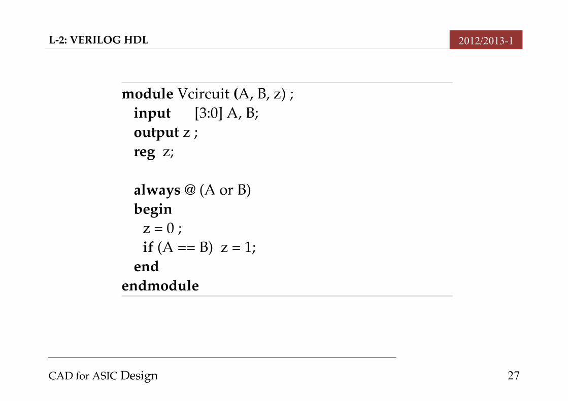
module Vcircuit (A, B, z) ;input [3:0] A, B;output z ;reg z;
always @ (A or B)begin
z = 0 ;if (A == B) z = 1;
endendmodule
L2: VERILOG HDL 2012/2013-1
CAD for ASIC Design 27

L2: VERILOG HDL 2012/2013-1
Verilog syntax requires any signal assigned a value inside an always block has to be a variable of type reg ; hence z is declared as reg.
Since z depends on A and B, these signals are included in the sensitivity list.
Blocking assignments, denoted by “=” symbol is used. The assignment completes and updates its LHS before the next statement is evaluated.
We will cover nonblocking assignment, denoted by <= symbol later on.
CAD for ASIC Design 28