introduction to system software and operating systems
TRANSCRIPT

ChapterChapterChaChaptepte
Introduction
I n the previous chapters, we have discussed different Intel microprocessors andperipherals. The discussion started with 8086, the first 16-bit microprocessor and conti-
nued upto the most recent microprocessor the Pentium family. If we observe the evolutionfrom 8086 onwards, the developmental trend mainly centred around the improvements inarchitecture, manufacturing technology and instruction set. These developments were aimedeither at improving the operating speed or at imparting more flexibility to the programmer.These developments in architecture and instruction set extend more and more support forthe system softwares, operating systems and even high level languages to make the previoustedious microprocessor based systems more and more user friendly.
The early microprocessor systems were programmed in machine language wherein theprogram code used to be a sequence of ‘1’s and ‘0’s, and writing programs in machine lan-guage was extremely tedious. All operations and operands in a machine language programare specified in terms of a numeric code. To avoid the obvious problems in machine languageprogramming, a need was felt to design a language where the commands and the instruc-tions could be specified in some user friendly format. Thus a symbolic assembly language hasbeen developed where the programmer may use ‘mnemonics’ for the instructions, directivesand operators for the commands and labels for the data and addresses.
The overhead task of coding the assembly language programs was initially left to theprogrammers which again increased the chances of human errors. Moreover, the codingoverhead resulted in reducing the programmer’s efficiency. The assemblers were designed totranslate these programs written in the form of mnemonics and directives into the equiva-lent machine coded version of the assembly language program.
Introduction to SystemSoftware and Operating
Systems
Introduction to SystemSoftware and Operating
Systems

528 Advanced Microprocessors and Peripherals
Although the assembly language programs are easier to write and understand as com-pared to machine language programs, yet the assembly language programmer need to havegood knowledge of the system architecture and also about how and where the program anddata should be stored. High level languages were developed to solve these problems. In highlevel language programming, the program codes are more readable and understandable toeven nontechnical programmers. The programming in high level languages is comparativelyeasier, more user friendly and even machine independent. The high level language program-ming needs a language translator that converts the high level language programs into theexecutable codes. A compiler translates a high level language program into an executableversion of the program. The recent compilers provide a number of advanced programming,debugging and development tools, besides coding the programs.
In the early systems, the system analyst had to carry out the tedious task of keeping thetrack of the system resources, like program decks, memory and I/O devices. For example, theprogrammer had to collect the different program object decks and put them together forexecution. A system software component called as loader was then developed to take overthis task of collecting all the required object modules, prepare the executable code from themand place it physically in memory for execution. All these programs (assembler, compiler,loader, etc.) are named system software. The operating system is an important piece of soft-ware, which primarily performs the task of the system resource management. It also pro-vides a more user friendly way of communicating with the system resources via a set ofoperating system commands.
This chapter presents a very brief overview of these system software components—assem-blers, loaders, linkers, compilers and operating system.
12.1 ASSEMBLER
12.1.1 Assembler—An Introduction
An assembler is a program that accepts an assembly language program as input and con-verts it into an object module, and prepares information for loading the program into memoryfor execution. The loader (linker) program further converts the object module prepared bythe assembler into executable form, by linking it with other object modules and library mod-ules. The final executable map of the assembly language program is prepared by the loaderat the time of loading into the primary memory for actual execution. The assembler preparesthe relocation and linkages information (subroutine, ISR and other programs) for loader.The operating system that actually has the control of the memory which is to be allotted tothe program for execution, passes the memory address at which the program is to be loadedfor execution and the map of the available memory to the loader. Based on this informationand the information generated by the assembler, the loader generates an executable map ofthe program and further physically loads it into the memory and transfers control to it forexecution.
Thus the basic task of an assembler is to generate the object module and prepare theloading and linking information. Figure 12.1 shows the basic function of an assembler.
An outline of the assembler functions and the design procedure of assemblers are nextpresented briefly.

Introduction to System Software and Operating Systems 529
12.2.2 General Assembler Design Concepts
In the following discussion, we will describe the design steps in the light of assembler design.As a first step in the design, we will have to specify the task, i.e. what exactly is to be done.
For this, we will model the procedure followed by a machine language programmer whowrites the program in terms of mnemonics and then converts it to machine codes usingopcode tables and instruction set details.
Let us consider a small 8086 ALP for conversion into its machine level program as shownin Program 12.1
ASSUME CS:CODE,DS:DATADATA SEGMENT
NUM1 EQU 55HNUM2 EQU 80HMULT DW 04H DUP (?)
DATA ENDSORG 0100HCODE SEGMENT
MOV AX, DATAMOV DS,AXMOV BL, NUM1MOV CL,NUM2MOV AL, 05HMOV CH, 02
XXX: MUL BLMOV [MULT], AXMUL CLMOV [MULT+2],AXDEC CHJNZ XXXMOV AH, 4CHINT 21H
CODE ENDSEND
Program.12.1Program.12.1Program.12.1Program.12.1Program.12.1 An Example Program
Fig. 12.1Fig. 12.1Fig. 12.1Fig. 12.1Fig. 12.1 Function of an Assembler
Machine Codesand Other Data Base
AssemblerAssembly
Language Module(With proper syntax)
Object Module andLoader Information

530 Advanced Microprocessors and Peripherals
The procedure of assembling a program proceeds statement by statement sequentially.The first phase of assembling is to analyse the program to be converted. This phase, gener-ally called as pass1, defines and records the symbols, pseudo-operands and directives. Fur-ther it analyses the segments used by the programs, types of labels and their memory re-quirements. The second phase, called as pass2, looks for the addresses and data assigned tothe labels. It further finds out codes of the instructions from the instruction machine codedatabase and the program data. It then generates the relocation database from the dataavailable in pass1. It further processes the pseudo operands and directives. It is the task ofan assembler designer to select the suitable strings for using them as directives, pseudo-operands or reserved words, and decide their syntaxes for specification.
In the given example, the directive ‘ASSUME’ informs the assembler that the register CSis to be initialized with the address allotted by the loader to the label CODE and DS issimilarly to be initialised with the address of label DATA. The next statement ‘DATA SEG-MENT’ directs the assembler that the label DATA is the logical name of a memory segmentand it also marks the starting of the segment. The two EQU operators assign the numericvalues 55H and 80H to the labels NUM1 and NUM2 respectively. The next statement ‘MULTDW 04H DUP (?)’ reserves four word addresses for the label MULT and leaves the fouraddress uninitialized due to the directive ‘DUP (?)’. The next statement ‘DATA ENDS’ markthe end of the segment named ‘DATA’. To find out the memory requirements of the DATAsegment, the assembler maintains a counter called as location counter (LC). The LC is ini-tialized with 0000 for ‘DATA’ segment. The first label NUM1 is a byte operand, hence the LCis incremented by one, i.e. the first address 0000 is allotted to the label NUM1. The secondlabel NUM2 is also a byte operand hence the LC is again incremented by one, i.e. the nextaddress 0001 is allotted for the storage of the label value NUM2. The next label MULTrequires four words, i.e. eight bytes for its storage. The location counter is thereforeincremented by eight and the label MULT is allotted to the first of the eight addresses. Thusat the end of the segment, the location counter contains the number of bytes required for thesegment. This information and the addresses allotted to each label are stored in a table forfurther use by the assembler. The ‘ORG 0100H’ statement directs the assembler to directlyassign the address 0100H to the following label. In other words, the current content of thelocation counter may be saved somewhere else and it may be loaded with value 0100H. TheLC, may then be incremented as usual. In case of code segment, the location counterupgradation operation requires the database of instruction types and their lengths in bytes.For each of the instructions in sequence, the required number of bytes may be found outfrom the database and the LC may be modified accordingly. Whichever instruction is foundwith a label, the label and the corresponding location counter contents are stored in a table.If any data label is found out, its respective allotted address is substituted at the place of thelabel. This procedure continues till the end of the segment marked by the ‘ENDS’ directive.At the directive ‘END’, the procedure is stopped after storing and generating the data intothe required database formats. The contents of the location counter at the end indicates thenumber of memory bytes required for storing the program. A typical assembler may gener-ate a database as shown in Fig. 12.2, for the example Program 12.1 in pass 1.
In pass 2, the assembler again reads the source program and prepares a relocatable mapof each segment individually from the data made available by pass 1. It initializes or reservesthe segment memory map as required by the individual segments. It then resolves the sym-bolic references. In other words, it substitutes the values of the constants, variables and

Introduction to System Software and Operating Systems 531
SYMBOL TABLE_DATASR. LABEL LOCATION COUNTER TYPE MEMORYNO. (SYMBOLS) (RELATIVE ADDRESSES) IN BYTES1. DATA 0000 SEGMENT -2. NUM1 0000 CONSTANT 013. NUM2 0001 CONSTANT 014. MULT 0002 VARIABLE 08
000A
SYMBOL TABLE2_CODESR. LABEL LOCATION COUNTER TYPE MEM. INNO. (SYMBOLS) (RELATIVE ADDRESSES) BYTES. 1. CODE 0100H SEGMENT - 2. MOV 0100H MNEMONIC 03 3. DATA 0103H LABEL - 4. MOV 0103H MNEMONIC 02 5. MOV 0105H MNEMONIC 02 6. NUM1 0107H LABEL DATA - 7. MOV 0107H MNEMONIC 02 8. NUM2 0109H LABEL DATA - 9. MOV 0109H MNEMONIC 0210. XXX 010 BH LABEL -11. MUL 010 BH MNEMONIC 0212. MOV 010 DH MNEMONIC 0313. *MULT 0110 H LABEL_DATA_ADDR. -14. MUL 0110 H MNEMONIC 0215. MOV 0112 H MNEMONIC 1116. DEC 011CH MNEMONIC 0117. JNZ 001DH MNEMONIC 0218. XXX 001FH LABEL_CODE_ADDR. -19. MOV 001FH MNEMONIC 0220. INT 0121 MNEMONIC 02
* This instruction requires its implementation using other instructions as discussed further.Type Definitions:
LABEL-1ST time defined label in Data Segment.MNEMONIC-Instruction Mnemonic.SEGMENT-Logical name of a segment.LABEL_DATA-Label already defined in data segment DATA.LABEL_DATA_ADDR-Label already defined in data segment of which the relative Address is to be substitutedhere.LABEL_CODE_ADDR.-Label already defined in code segment of which the relative address in the codesegment is to be substituted here.
Note It may be noted that the mnemonics and the reserved words like ‘constant’, ‘DATA’ or ‘CODE’ are not allowedto be used as labels.
Fig. 12.2Fig. 12.2Fig. 12.2Fig. 12.2Fig. 12.2 Database Generated by Pass 1
addresses represented by labels. Further, it refers to the opcode database and rule base toconvert the instruction sequence in opcodes. In this pass, the assembler also finds out thesyntax errors if any. In the generated opcode sequence, it further finds out the relocatablelabels, addresses, linkages and segment parameters for the loader, and stores them. The
532 Advanced Microprocessors and Peripherals
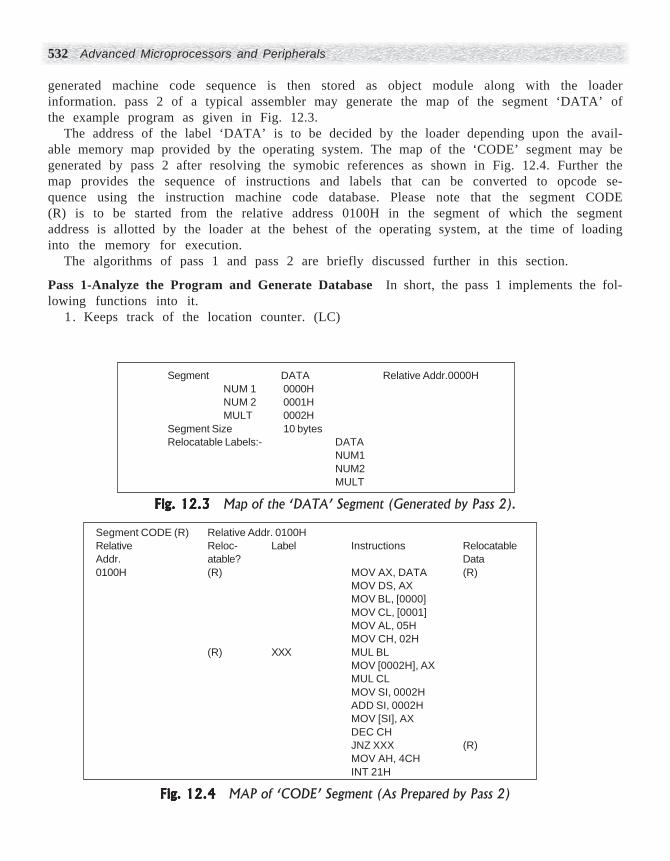
generated machine code sequence is then stored as object module along with the loaderinformation. pass 2 of a typical assembler may generate the map of the segment ‘DATA’ ofthe example program as given in Fig. 12.3.
The address of the label ‘DATA’ is to be decided by the loader depending upon the avail-able memory map provided by the operating system. The map of the ‘CODE’ segment may begenerated by pass 2 after resolving the symobic references as shown in Fig. 12.4. Further themap provides the sequence of instructions and labels that can be converted to opcode se-quence using the instruction machine code database. Please note that the segment CODE(R) is to be started from the relative address 0100H in the segment of which the segmentaddress is allotted by the loader at the behest of the operating system, at the time of loadinginto the memory for execution.
The algorithms of pass 1 and pass 2 are briefly discussed further in this section.
Pass 1-Analyze the Program and Generate Database In short, the pass 1 implements the fol-lowing functions into it.
1 . Keeps track of the location counter. (LC)
Segment DATA Relative Addr.0000HNUM 1 0000HNUM 2 0001HMULT 0002H
Segment Size 10 bytesRelocatable Labels:- DATA
NUM1NUM2MULT
Fig. 12.3Fig. 12.3Fig. 12.3Fig. 12.3Fig. 12.3 Map of the ‘DATA’ Segment (Generated by Pass 2).
Segment CODE (R) Relative Addr. 0100HRelative Reloc- Label Instructions RelocatableAddr. atable? Data0100H (R) MOV AX, DATA (R)
MOV DS, AXMOV BL, [0000]MOV CL, [0001]MOV AL, 05HMOV CH, 02H
(R) XXX MUL BLMOV [0002H], AXMUL CLMOV SI, 0002HADD SI, 0002HMOV [SI], AXDEC CHJNZ XXX (R)MOV AH, 4CHINT 21H
Fig. 12.4Fig. 12.4Fig. 12.4Fig. 12.4Fig. 12.4 MAP of ‘CODE’ Segment (As Prepared by Pass 2)

Introduction to System Software and Operating Systems 533
2. Determines the values of the symbols and stores them for pass 2. (ST)3. Finds the length of the instructions from the machine code table. (MCT)4. Processes variables, constants and pseudo-ops like DW, DUP DB,EQU. (PSOP)5. Stores the literals and their values in a database for pass 2. (STLT)The flowchart of pass 1 is shown in Fig. 12.5.
Store Label and Content of LC inSymbol Table (ST)
Initializeother LCfor other segment
Determine MemorySize required
Processliterals(STLT)
Upgrade locationcounter (LC)
Go toPass 2
Determine MemorySize and Initialize
Yes
Yes
Yes
YesYes
Found DBDWDD
EQU?
ENDS?
END?
Not found
No No
No No
No
AnyLabel?
Search Pseudo-OpTable
(PSOP)
Search MachineCode
Data base (MCT)
Get length of the next instruction
Read SourceProgram
Initialize
Fig.12.5Fig.12.5Fig.12.5Fig.12.5Fig.12.5 Flow chart of pass 1
Pass 2- Generate Machine Codes for the Program This pass typically carries out the followingfunctions.
1 . Finds out the values of the labels from pass1 database and substitutes them in theinstruction sequence for further coding. (FST)
2. Finds out the machine codes for the instructions in the sequence from the machineopcode table.(FMCT)
3. Generates the data from the DB,DD and EQU operators. (GD)

534 Advanced Microprocessors and Peripherals
4. Processes pseduo-ops using the pseudo_op table. (PSOPT)5. Generates and stores a database for loader. (GDLDR)Figure12.6 shows a typical algorithm for pass 2 of an assembler.
EQU?
DBDW
?
END?
Matchfound
Notfound
SearchPSOPT forpseude-op
Search opcodetable (FMCT)
Allot memoryaddresses and
initialize
Determinesize
Store object module
and EXIT
DUP?
No
Yes
Yes Yes Yes
No
NoNo
Allot memoryaddresses
Prepare and storeloader information
Get Instructionlength, type, and
opcode
Decide operandcodes
Decide the code of completeinstruction
Update LoctionCounter (LC)
Read
Initialize
Initialize
Fig. 12.6Fig. 12.6Fig. 12.6Fig. 12.6Fig. 12.6 Pass2 Algorithm
12.1.3 Databases in Assembler Design
In this section, we will specify the databases required for the implementation of the twopasses of assembler. Actually, the algorithm, databases and their formats are all dependenton each other and hence the design procedure is iterative. In each iteration, the designermodifies the algorithm, databases and their formats one by one to improve the performanceand make the software features functional.

Introduction to System Software and Operating Systems 535
The assembler requires a database containing the mnemonics, their opcodes, all the for-mats of allowed data and the instruction lengths of each instruction. This information maybe stored in an array in the coded formats like ASCII, EDCBIC, etc. This database may becalled ‘Machine opcode table’. The other database named ‘pseudo operand table’, containsthe information about the pseudo-operations allowed by the assembler, their formats andaddresses of the routines to process the pseudo-ops. The corresponding data, if any, is passedto the processing routine as input for further action. One of the possible formats of the sym-bol table is shown in Fig. 12.2. The pseudo-op table format may also be similar to that of thesymbol table format. The assembler also maintains a database to keep track of the availablesystem and the CPU resources for the program. It may maintain information about allot-ment of different registers and memory locations to the program variables and constants.Figure 12.7 shows different databases referred by an assembler and their corelation with thetwo passes.
Fig. 12.7Fig. 12.7Fig. 12.7Fig. 12.7Fig. 12.7 Databases Required by an Assembler
SourceProgram
ObjectCode and Loader
Information
Copy of the Source
Program
MachineOpcode
Table (MCT)
SymbolTable (ST)
LateralTable (LT)
LocationCounter 1
(LC1)
Pseudo-opTable
(POPT)
Resources(Register,Memory)
Record
Storage MediaHandler
LocationCounter 2
(LC2)
Pass 1 Pass 2

536 Advanced Microprocessors and Peripherals
12.2 LOADERS AND LINKERS
An assembler produces an object program (.OBJ) from the source program (.ASM). The ob-ject program is further processed by a linker program that produces a map of the objectprogram for execution in memory, along with the library and other routines. The loaderprogram assures that the object program and the required supporting routines are placed inmemory in an executable form. The assembler itself can place the object program in memoryand further transfers control to it for its execution. However, in that case both the assemblerand the object program remain in memory. The assembler may even occupy much morememory compared to the object program, thereby increasing the memory requirement.Moreover, every time the object program is executed at a specified memory location, theassembler needs to be loaded in memory for the translation, causing wastage of time.
To overcome these problems, the loader was introduced by system designers. A loaderprogram is responsible for placing the object programs into memory and preparing them forexecution. In a simple loading scheme, the assembler stores the machine coded program in asecondary memory and the loader itself is in RAM. At the time of execution, along with theexecutable code, the loader is in the RAM. The loader is a small program compared to anassembler, and requires less memory. Thus more memory is available for the user’s pro-gram. The object codes are stored into the secondary memory. The translation scheme isfollowed by various types of loaders, e.g. compile-and-go, absolute, relocating, direct linking,dynamic loading and dynamic linking.
A typical loader performs four basic functions as given:1. Allocates space in memory for execution of user’s program.2. Links the library routines and other programs (if necessary) with the user program.3. Recalculates all the address dependent codes with respect to the address allotted for
execution.4 . Loads the code into the memory for actual execution.The various types of loaders carry out these tasks in different manners. The following text
briefly explains various loading schemes.
Compile and Go Loaders A primary method of loading the program for execution is to runthe assembler in one part of the memory and directly place the resulting codes in the otherpart of the memory where they are to be executed. After the assembly procedure is over, thecontrol is transferred to the generated executable code for its execution. This is very simpleto implement but has serious disadvantages. For example, this scheme requires morememory, as the assembler is all the time available in RAM. This requires assembly everytime, the program is executed. In this scheme, it is difficult to handle the multisegmenttasks, as it does not provide any data protection. Figure 12.8 shows the working of compileand go loaders.
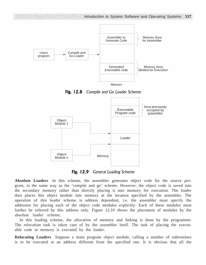
General Loader Scheme In this loading scheme, once the translation process is over, theassembler is replaced from the RAM and the same translated code may be placed for execu-tion, in the memory area occupied by the assembler. This task is carried out by the loaderprogram. The loader resides in the RAM at the time of execution. However, a loader is sup-posed to be smaller in size and hence it leaves more free area for the user’s program. Also,the program need not be retranslated at each time of execution. The scheme is shown inFig. 12.9.
Introduction to System Software and Operating Systems 537
Absolute Loaders In this scheme, the assembler generates object code for the source pro-gram, in the same way as the ‘compile and go’ scheme. However, the object code is saved intothe secondary memory rather than directly placing it into memory for execution. The loaderthen places this object module into memory at the location specified by the assembler. Theoperation of this loader scheme is address dependent, i.e. the assembler must specify theaddresses for placing each of the object code modules explicitly. Each of these modules mustfurther be referred by this address only. Figure 12.10 shows the placement of modules by theabsolute loader scheme.
In this loading scheme, the allocation of memory and linking is done by the programme.The relocation task is taken care of by the assembler itself. The task of placing the execut-able code in memory is executed by the loader.
Relocating Loaders Suppose a main program object module, calling a number of subroutinesis to be executed at an address different from the specified one. It is obvious that all the
Fig. 12.8Fig. 12.8Fig. 12.8Fig. 12.8Fig. 12.8 Compile and Go Loader Scheme
ObjectModule 1
ObjectModule n
ExecutableProgram code
Area previouslyoccupied byassembler
Loader
Memory
Fig. 12.9Fig. 12.9Fig. 12.9Fig. 12.9Fig. 12.9 General Loading Scheme
Usersprogram
Compile andGo Loader
Assembler toGenerate Code
Memory Areafor Assembler
Memory Areaallotted for Execution
Generated Executable code
Memory

538 Advanced Microprocessors and Peripherals
subroutine addresses and the corresponding CALL addresses may change, and hence thecomplete translation process needs to be repeated.
The relocating loaders were introduced to avoid the possible retranslation of all the rou-tines, even when a single routine address is changed. In this scheme, the assembler assem-bles the source program and also prepares a database containing relocation, i.e. addresssensitive code information. This relocation information is passed to the loader program tomake the necessary corrections at the time of loading. The relocation information containsall the address sensitive labels, for example, subroutine names, segment names, variablenames which require memory for program execution, their maximum memory requirements,etc.
The relocating loader takes care of the new memory address allotment to the subroutines,variables and target jump addresses besides physically loading the executable code inmemory for further execution.
Direct Linking Loader This type of loading scheme overcomes all the already discussed dis-advantages of the previous loading schemes. Besides taking care of relocation, this type ofloader also performs the task of linking various object modules of a user program and placingthem physically in the memory for execution. The direct linking loader offers an advantageof allowing the use of multiple modules, segments and routines in a user program and stillgiving full flexibility for cross referencing the data or variables from all the modules andsegments.
For this type of loader, the assembler prepares the relocation, cross-referencing and link-ing database, that has the following information:
1. Size of the segment or module.2 . List of all the symbols to be cross-referenced and their relative location in the
respective routine.
Fig. 12.10Fig. 12.10Fig. 12.10Fig. 12.10Fig. 12.10 Loading by an Absolute Loader
MAIN
1000
2000
3000
MemoryAddresses
Memory
Subroutine1
AbsoluteLoader
Subroutine 1(2000)
Main(1000)
Subroutine 2(3000)
Subroutine2

Introduction to System Software and Operating Systems 539
3. List of all the symbols not defined but referenced in the segment.4 . Information about the relocatable data, variables, addresses and constants.5 . The relative addresses of all the relocatable data and lables in the respective routines.
Dynamic Loading and Linking Let us assume a situation where the program to be executed islarger in size than the semiconductor memory available in the system. In such cases, thelarge program, that remains in secondary memory, is divided into segments or pages ofsmaller size and only those segments or pages are loaded into the memory which are re-quired for execution at that instant. Once the execution of these segments or pages is com-pleted, they may be replaced from the memory by the new segments or pages required forexecution. The result of the previously executed pages may be stored back into the secondarymemory, if it is required for further execution. This type of loading scheme is used by all therecently developed personal computer systems.
A major disadvantage of all the previous loading schemes is that even if a module is refer-enced but never executed, these loaders used to link it and place it in the memory. In thedynamic linking scheme, all the routines are coded (translated) and stored in the secondarymemory. Only those, actually required for the execution at that instant, are linked andplaced in the memory just before execution. Thus the process of linking and loading goeshand-in-hand with execution of the user’s program.
12.3 COMPILERS
12.3.1 Compilers—An Introduction
In the journey of the microprocessor based systems from the crude computing machines tothe recent supercomputers, the development of personal computers is supposed to be a mile-stone. The most important feature of a personal computer is its ability to process and executea program that is written in a more user friendly, readable and easy to understand languageform called as ‘high level language’. The programs written in high level languages can moreeasily be understood, and hence the debugging is somewhat easier. The only disadvantage ofthese high level language programming systems is—the EXE files (equivalent executablecodes) are bigger in size, hence require more memory and time for execution.
The ‘compiler’ is a program that converts a high level language program (source program)into an equivalent code, called as object or target program. In other words, the compiler is alanguage translator that processes a high level language source program to create its equiva-lent assembly code that can be further converted to its executable form using an assembler.Of course, it may require support from a few other programs like library routines, linkers,loaders and operating systems. A typical compiler operation can be modelled as shown inFig. 12.11.
12.3.2 A Language Processing System
As discussed earlier, a compiler may need support from other system softwares, operatingsystem and libraries, in the process of translating the high level language programs into thecorresponding machine codes. In general, a language processing system that utilizes theservices of a compiler is as shown in Fig. 12.12.

540 Advanced Microprocessors and Peripherals
An input source program may be written using a number of modules, macros and othersource programs. A preprocessor is used to collect the different fractions of the source pro-grams from whereever they are available and form a unified string of source language state-ments, for further processing.
The compiler may also create a target assembly language program from the source codecreated by the preprocessor. An assembler in this case is further used to convert the assem-bly language code into a relocatable machine code. The loader and linker programs, workhand in hand with each other to link the relocatable code generated by the assembler withthe library routines to form and load the final machine code version of the program into thememory for execution.
Fig. 12.11Fig. 12.11Fig. 12.11Fig. 12.11Fig. 12.11 A Basic Compiler Model
Fig. 12.12Fig. 12.12Fig. 12.12Fig. 12.12Fig. 12.12 A Typical Language Processing System
CompilerHigh Level Language
Program (I/p)(e.g. C, PASCAL, etc.)
Executable machine code andLoader Information
Support from other systemsoftwares and O.S.
I/P programs
Error messages
LibraryRelocatableobject files
Preprocessor
Compiler
Assembler
Loader, Linker
(Source program)
Target assembly program
Relocatable machine codes
Absolute machine code

Introduction to System Software and Operating Systems 541
12.3.3 Compiler Operation
The compiler is a very comprehensive and complex program to design. The complete com-piler operation is performed in a set of phases of operation. In each of these phases, thecompiler accepts input, in the predefined form, from the previous phase, then carries out theallotted task on it and again passes it to the next phase for further processing. In this pro-cess, the source code undergoes different transformations, till the compilation is over. Thedifferent phases of compiler operation are shown in Fig. 12.13.
Source Code
Lexical Analysis
Syntax Analysis
Semantic Analysis
Intermediate Code Generation
Code Optimization
Code Generation
Target Program
Symbol TableManager
ErrorHandler
Fig. 12.13Fig. 12.13Fig. 12.13Fig. 12.13Fig. 12.13 Phases of Operation of a Typical Compiler
The different phases of operation of a compiler are discussed briefly, in the following text.
Lexical Analysis The lexical analysis phase is the first phase of the compilation process. Thelexical analyser reads the source program one character at a time and converts it into asequence of meaningful primitive units called tokens. The key words ,constants, identifiersand operators used in a program are examples of tokens. Each token may be described by aregular expression. The comments and white spaces like tabs and blanks are ignored whileconverting the source code into a sequence of tokens. In the lexical analysis phase, the com-piler uses a finite automata model to represent each token. Each token may be viewed as aregular expression and thus may be represented by a finite automata. The output of thisphase, which is a sequence of tokens is fed to the syntactic analyser or parser.
Syntax Analysis In this phase, the sequence of tokens generated by the lexical analyser ischecked for any syntax error. The syntax of a programming language may be described by acontext free grammar. The detais about the context free grammar may be found from anybook on formal language theory or compiler design. Interestingly, a context free grammar isthe generator of a set of strings which defines the instruction syntax of a programming

542 Advanced Microprocessors and Peripherals
language. The input to the syntax analyser is a sequence of tokens and the syntax analyserchecks whether this sequence of tokens has been appropriately formed according to thegrammatical rules of the language. This procedure is known as parsing. A number of parsingstrategies have been developed and these may be broadly categorised as (a) Top down pars-ing and (b) Bottom up parsing. The parser accepts the sequence of tokens as inputs andgenerates a tree like structure known as parse tree. If the sequence of tokens forming aninstruction in a program has not been approriately generated, the parser produces an errorsignal.
Semantic Analysis The type checking of the operands and the respective operators alongwith checking of the argument type, etc. are carried out in semantic analysis. Here, thecompiler checks whether each of the operator has the appropriate operands which are per-mitted by the source language or not. For example, this phase may report an error if a realnumber is used to index an array.
The semantic analysis can be performed during the syntax analysis phase, intermediatecode generation or the final code generation phase.
Intermediate Code Generation In this phase of operation, the parse tree which was gener-ated by the syntax analyser is transformed into an intermediate language known as ‘threeaddress code’ in which each statement usually contains three addresses, two for the oper-ands and one for the result. It is important to note here that many compilers do not generatea parse tree explicitly but generate the intermediate code in the syntax phase directly.
Code Optimization It is extremely important to produce an efficient object program. Theoptimizing compilers apply some transformations to the intermediate codes generated fromthe source program. For each source program, there exists a number of object programs thatimplement the same function. It is thus important to optimise the three address codes so asto minimize the memory requirement and execution time of the program.
Various code optimization techniques are used by the recently available compilers. Ofcourse, there is a great variation in the amount of the optimization of code achieved bydifferent compilers. This depends upon the optimization techniques and algorithms used bythe compiler.
Symbol Table Management A symbol table is a data structure that contains a record for eachidentifier with the fields for the attributes of the identifier (label). The attributes provideinformation about the storage allocated for an identifier, its type and scope (where it is validin the program). In case of procedure names, the attributes provide information about theprocedure type, method of passing arguments and type of its return results, etc.
Code Generation The final phase of the compiler operation is the code generation, whichusually generates a relocatable assembly code. Memory locations are selected for each of thevariables used by the source program. Then each of the intermediate instructions are trans-lated into a sequence of machine instructions that perform the same task. The assignment ofregisters and memory locations to variables is a crucial task in this phase.
Error Handling In each of the above discussed phases, the compiler may encounter errors.However, after detecting an error at any phase, the compilation process proceeds so thatfurther error finding will be possible.

Introduction to System Software and Operating Systems 543
12.3.4 Example Translation of a Statement
Let us now consider translation of an example statement given below by a typical compiler.SUM = SUM + INTEREST * SUM
Lexical and Syntax Analysis Phase The lexical analysis phase reads the characters in thesource program statement and groups them into a meaningful sequence of characters calledas tokens. We assume id1 and id2 are the identifiers corresponding to the variables ‘SUM’and ‘INTEREST’ respectively. The above statement, after lexical analysis, yields;
id1 = id1 + id2 * id1The syntax analysis creates the hierarchical structure (parse tree) from the above token
s t ream.The semantic analysis checks whether the operands are allowed by the language gram-
mar or not.
Intermediate Code Generation As has been described, the intermediate representation mayhave various forms. The three-address-code is like an assembly language program of amicroprocessor in which all the memory locations can be used as registers. The three-address-code consists of the instructions each of which has at the most three addresses asdiscussed earlier. The above statement, after intermediate code generation, yields thefollowing sequence of instructions.
temp1 := id2 * id1temp2 := id1 + temp1
id1 := temp2The code optimizer next reduces the number of instructions from three to two, as given:
t e m p := id2 * id1id1 := id1 + temp1
Finally for code generation, we should have full knowledge of the machine architectureand the instruction machine codes. Here we have used only two registers R1 and R2 forstoring the variables and we have assumed that the architecture supports the data transferinstruction MOVF R1,R2 and the arithmetic instructions MULF and ADDF.
The overall processing of the example statement is shown in Fig. 12.14.
12.4 OPERATING SYSTEMS
12.4.1 Operating Systems—An Introduction
A designer of a small microprocessor system, takes care of a number of considerations likememory management, i.e. availability of memory for programming, secondary storage man-agement, i.e. effective use of secondary memory and communication and management of I/Odevices, besides the main task of programming. Due to these additional tasks of systemmanagement, many problems are faced by the programmer. A program called operatingsystem overcomes these problems. In general, the term operating system denotes the pro-gram modules within a computer system which govern the control, use and management ofthe available computer system resources such as memory, secondary memory, I/O devices

544 Advanced Microprocessors and Peripherals
Fig. 12.14Fig. 12.14Fig. 12.14Fig. 12.14Fig. 12.14 Translation at the Example Statement
and even the processor and the software resources. The operating system, indeed, plays amultidimensional role in the present day computing systems.
Figure 12.15 shows a typical structure of an operating system.In the following text, we present the different functions of the operating systems.
SUM : = SUM + INTEREST *SUM
Lexical Analysis
No. Identifier Attributes
Syntax Analyser
Semantic Analyser
Intermediate CodeGenerator
Code Optimizer
Code Generator
MOVF Id2, R1
MOVF Id1, R2
MULF R1, R2
MOVF Id1, R1
ADDF R2, R1MOVF R1,Id1
temp 1: = Id2 Id1
temp 1: = Id2 Id1
temp 2: = Id1 + temp 1Id1: = temp 2
Id1: = Id1 + temp 1
SyntaxErrors
Operand Type Errors
Id1 : = Id1 + Id2 *Id1
: =
Id1Id1
Id1
Id21
2
SUM
Symbol Table
INTEREST

Introduction to System Software and Operating Systems 545
12.4.2 Views of an Operating System
Basically, an operating system is a software that stands between the bare system hardwareand the user’s programs to manage the system resources like memory, processors, I/O de-vices and software modules when they are being shared by different processes of a user task.Moreover, it tries to make the system programmer interface more user friendly.
Mainly the operating system, is viewed in two different angles as given:(i) As a user interface.
(ii) As a manager of resources.
Operating System as a User Interface From the user’s point of view, the operating systemacts as an interface between a user’s program and the physical computer hardware. Theoperating systems provide user of a computing system, a friendly programming and commu-nication environment. An operating system provides various commands for carrying outdifferent user tasks and system tasks. The commands are in the form of purpose orientedmeaningful character strings, rather than the set of hex codes. The operating systems alsoprovide different functions to assist the user in programming as well as system mainte-nance. Table 12.1 shows some user interface and system maintenance functions along withthe corresponding commands.
These functions may be provided to the different categories of users like end users, pro-grammers, system managers, etc. All of these functions or commands may not be available toall the types of users.
Systems and application programmers often invoke services of operating system fromtheir programs by means of ‘system calls’, which are sometimes called application program-ming interfaces. System commands issued by the command language at the command
File Management
SystemProgram
ApplicationProgram
Second.Memory
MainMemory
SystemHardware
Pro
cess
orM
anag
emen
t
Dev
ice
Man
agem
ent
Primary MemoryManagemant
CPU
IO
User Interface
Fig. 12.15Fig. 12.15Fig. 12.15Fig. 12.15Fig. 12.15 Structure of a Typical Operating System

546 Advanced Microprocessors and Peripherals
prompt are converted into the system calls and then executed. Most of the operating systemsprovide the user with the facility of entering the commands directly using an interface ter-minal. Advanced graphical user interface provides a means of conveying the commands tothe system using windows and mouse driven command menu.
Operating System as a Manager of Resources In general, a computer system has the follow-ing resources
(i) Processor(ii) Main memory and secondary memory
(iii) Input/output devices(iv) Information (software)
As discussed earlier, an operating system acts as a manager of the resources. While man-aging each of the above resources, it carries out the following tasks.
(i) Keeps track of the resources—The OS keeps the track of the availability orunavailability of the resources.
(ii) Enforces the policy that determines who gets, what, when and how much out of thedifferent processes asking for the resources. The operating system decides whichprocess is due for the resource access and for how much time.
(iii) Allocates the resources—If a process is due for the access of a resource and if theresource is free, the operating system allocates it to the requesting process, for theprespecified time duration and to the prespecified extent.
(iv) Reclaims the resources—Operating system reclaims a resource from a process to whichit was previously allotted if (a) either the process is completed or (b) the duration forwhich it was allotted is over or (c) another higher priority process is asking for theresource.
12.4.3 Structure of an Operating System
Hierarchical Operating System Model An operating system manages operations of a compu-ter system and provides a possibly large number of user accessible services. In a multiusermultiprogramming system, it has to provide the working environment and keep track of thesame, for proper execution of programs. One of the major problems faced by the operatingsystem designers is how to manage the complexity of various functions while providing anamicable solution to the other design problems like maintainability and reliability. The expe-riences with large operating systems, built as integrated segments of code, have been dis-couraging in both of the above aspects. The contemporary systems are usually designed andimplemented in the form of hierarchy of levels of abstraction. This concept is an outgrowth ofthe concept of information hiding. The basic idea is to create a hierarchy of levels so that at
Table 12.1Table 12.1Table 12.1Table 12.1Table 12.1 Functions and Typical Commands
Functional Category Typical CommandsLogon and house keeping Login, Logout, Change passwordProgramme activities and Control Load, Run, AbortFile management Create, Delete, Rename, CopyStatus reporting Logged users, List active programmsSystem management Create account, List_error_log

Introduction to System Software and Operating Systems 547
each level of operation the details of operation of all the lower levels may be ignored. Eachlevel of abstraction provides a set of objects and primitive operations that may be used by allthe higher levels. In this process, each level may rely on the objects and the related opera-tions provided by lower levels. As an effect, each level of abstraction enriches the set offacilities provided by the hardware and all the intermediate levels. Table 12.2 shows a hier-archical operating system model.
Table 12.2Table 12.2Table 12.2Table 12.2Table 12.2 Hierarchical OS Model
Layer N a m e Objects Typical Operations5 . Command Language Environment Statement in a
In te rpre te r d a t a command language.4 . File system Files, devices Create, destroy, open, close
read, write.3 . Memory management Segments, Pages Read, write, fetch2 . Basic I/O Data blocks Read, write, Allocate, Free1 . Kernel Process Create, Destroy Suspend
Semaphores resume, signal, wait
The following text describes each of the above layers in brief.
Layer-1 This is often called as kernel or nucleus of an operating system. The kernel is theheart of the complete software. This keeps track of active processes by means of data struc-tures called as process control blocks (PCBs). A PCB is constructed for each process to depictthe state of the system. The layer contains a scheduler that selects a process to which theprocessor is to be allotted after the running process is completed. This layer also managesthe system interrupts as and when required. It also provides facilities for connecting serviceroutines to the hardware interrupts. Basic mechanisms for interprocess synchronization andcommunication like semaphores and message blocks are provided at this level.
Layer-2 This layer basically manages low level facilities for management of the secondarystorage, needed to support the main memory management on layer 3. The layer allows blocksof data to be shuffelled between the primary and secondary storages. A fairly low-level ab-straction of the secondary storage as a linear array of data blocks is provided by this level forreading and writing.
Layer-3 This level manages primary memory. It allocates memory for the programs to beloaded for execution, and frees it after the execution is over. Isolation of the distinct addressspaces (occupied by different processes) and some controlled forms of sharing memory arealso supported by this level. Virtual memory, which gives the illusion of having largermemory space at one’s disposal, than may be physically available, can be implemented atthis layer.
Layer-4 This layer provides facilities for long term storage and manipulation of the namedfiles. At this level, more sophisticated forms of space allocation and accessing data on second-ary storage level are implemented. Level 4 also manages external devices and peripheralssuch as printers and terminals.
Layer-5 This is the command language interpreter layer. This provides an interface be-tween the interactive users and the operating system. Modules at this level use facilities
548 Advanced Microprocessors and Peripherals
provided by the lower levels to accept the command lines from terminals. These input com-mand lines are then parsed to separate the commands from the parameters and to identifythe services required. System calls to other levels are employed to actually render the serv-ices. When requested to execute a program, the software at this layer creates the workingenvironment and invokes the related processes.
12.4.4 Operating System Examples
In this section, we discuss two of the most popular operating systems, viz. MSDOS andUNIX very briefly.
MSDOS The Microsoft Disk Operating System (MSDOS) was designed and developed byMicrosoft Corporation, USA. After its initial adoption for the IBM personal computer family,the MS-DOS is now popularly called as PC-DOS. The basic version of MSDOS has under-gone various major revisions and in this process, the PC-DOS is functionally tending to-wards the UNIX operating system, at both command language and system call levels.
The MSDOS is a single user, single process, single processor operating system, mainlydesigned for IAPX-86 based computers. Due to the confinement of the device-dependent codeinto one layer, the porting of MS-DOS has theoretically been reduced to writing of the BIOScode for the new hardware. At the command level it provides a hierarchical file system, I/Oredirection, pipes and filters. User written commands can be invoked in the same way as thestandard system commands, giving the appearance as if the basic system functionality hasbeen extended.
Being a single user system, it provides only rudimentary file protection and access con-trol. The disk space is allocated in terms of a cluster of consecutive sectors. The commandlanguage of MS-DOS has been designed to allow the user to interact directly with the oper-ating system using a CRT terminal. The principal use of the command language is to initiatethe execution of commands and programs. A user program can be executed under MSDOS bysimply typing the name of the executable file of the user program at the DOS commandprompt.
MSDOS System Calls The MSDOS calls are invoked from a user program by means of soft-ware interrupts. The processor registers or memory blocks create the required parameterenvironment for execution of the interrupts. These calls are generated by the INT instruc-tions, which, when executed, causes the processor to be interrupted in a similar fashion asthe hardware interrupts do.
A range of interrupt controlled system calls is available in MSDOS, but majority of thefunctions are provided by INT 21H, the MSDOS function call interrupt, that provides a widerange of different facilities. Each of these functions is identified with a hex function number,that is to be provided in register AH, at the time of execution of the INT 21H instruction. Theother registers are either used for passing the input parameters to the function or to get backthe results of the execution of the function. In addition to INT 21H, a few other interruptsmay be employed by MSDOS. For example, INT 10H can be used for manipulating ROMBIOS video driver functions, and INT33H can be used for manipulating mouse driver func-tions.
UNIX UNIX was developed at AT & T Bell Laboratories in late sixties by Ken Thompson andDennis Ritchie. It is the most popular multiuser time-sharing operating system primarily

Introduction to System Software and Operating Systems 549
intended for program development and document preparation environments. It is written inhigh level language ‘C’, with careful isolation and confinement of machine dependent rou-tines so that it may be quiet easily ported to different computer systems. As a result, differentversions of UNIX are available for personal computers, large mainframes and super-computers. Figure 12.16 shows the structure of the UNIX system.
Some of the important features of UNIX are listed, followed by their brief explainations.(i) Portability
(ii) Multiuser Operation(iii) Device independence(iv) Tools and tool building utilities(v) Hierarchical file system.UNIX is a portable operating system, in the sense that, it is able to operate on a wide
range of hardware. The designers of UNIX have confined the hardware dependent codes to afew modules in order to facilitate the porting. Unix supports multiple users on installationwith the appropriate memory management hardware and interface. In addition to local us-ers, remote users also have access to log-in-facilities and file transfer facilities between aUNIX host and the terminals in network configuration.
UNIX system provides abstraction of the input/output system where all the I/O devicesappear as sets of files to the users. Thus users can rely on a single, uniform set of file-manipulation system services, for both I/O and file management. This is sometimes referredto as device-independent I/O. For example, a text file may be printed by means of a copyoperation, where the destination ‘file’ is the printer device.
The most important feature of the UNIX operating system is the ease of building utilitiesand the available tools for utility-building. In UNIX, the user-built-utilities may easily beintegrated with the original frame due to its modular structure. UNIX provides a way ofcombining user-built-utilities with it, by means of its input/output redirection and pipeliningcapabilities.
The hierarchical file system of UNIX is designed to eliminate the need for volume aware-ness amongst its users. This is especially convenient in time sharing systems and network-ing configurations.
Fig. 12.16Fig. 12.16Fig. 12.16Fig. 12.16Fig. 12.16 Structure of UNIX System
Tools and UserProgrammes
Kernel
Shell (UNIXCommand Interpreter)

550 Advanced Microprocessors and Peripherals
The unix command language empowers its users to communicate with the system hard-ware and software using its set of commands. The UNIX users invoke commands by interact-ing with a command language interpreter called as shell. The shell is written as a userprocess, as opposed to being built in the kernel. When a user logs in, the system invokes acopy of the shell to handle further interactions with the user.
Summary
This chapter is initiated with a note on Role of system software and Operating Systems inthe advanced computer systems’. The assembler, that converts an assembly language pro-gram into its object code is discussed in significant details. The object code modules gener-ated by an assembler need to be linked with the other required routines or library modulesand then these modules are to be loaded in physical memory at a specified address beforeexecution. The loaders and linkers which work hand in hand to accomplish the task of link-ing and physical loading in memory, have been briefly explained. The compiler which per-forms the task of converting the high level language listings into equivalent instructionsequences has next been discussed along with an example conversion. Finally the operatingsystem, which is responsible for the optimal use and management of computer resources andalso for providing the appropriate interface with users, has been discussed briefly. This chap-ter concludes with a very brief note on the basic features of two of the most popular operatingsystems, viz. MSDOS and UNIX.
EXEREXEREXEREXEREXERCISCISCISCISCISESESESESES
12.1 What is an assembler?12.2 Explain the working of a typical assembler in pass1.12.3 Explain the working of an assembler in pass 2.12.4 Explain the function of location counter in an assembler.12.5 What do you mean by resolving the references in the process of assembling a program?12.6 Considering the program in program 3.1 ( page 94) as input to the assembler find
the outputs of the two phases of the assembler. Find out the contents of the locationcounter at the end of pass1 assuming it is initialised with zero.
12.7 For the given program in program 3.3 ( page 98), form the literal table and map ofthe code and data segments as prepared by a typical two pass assembler.
12.8 Enlist the functions of the two passes of a typical assembler .12.9 What are the databases and their contents required by an assembler?12.10 Explain the terms loader and linker.12.11 Differentiate the between a loader and a linker.12.12 Explain the following loading schemes.
(i) Compile and Go Loading (ii) Absolute Loading(iii) General Loading Scheme. (iv) Relocating Loaders(v) Dynamic Loading Scheme (vi) Dynamic Linking Loader Scheme
12.13 Out of the six types of loaders specified in Q.12.12., which scheme will be mostsuitable for IBM PC? Why?

Introduction to System Software and Operating Systems 551
12.14 Enlist the functions to be provided by a loading scheme for a system with virtualmemory?
12.15 ‘Loader and Linker functions of a computer system are dependent on each other’ -Elaborate.
12.16 What is the basic difference between the working of an assembler and that of acompiler ?
12.17 Explain working of different phases of a compiler.12.18 Enlist the different phases of working of a typical compiler.12.19 What is the difference between syntax analysis and semantic analysis?12.20 Explain the different databases used by compilers during the process of compilation.12.21 Prepare parse trees for the following statements.
(i) PRODUCTION = DAYS*(GROSS _PRODUCT_PER_DAY) - REJECTED(ii) ANUAL_INCOM = [SALARY*12 - DEDUCTIONS]+ BONUS
12.22 What do you mean by an operating system? Enlist different functions of a operatingsystem.
12.23 Discuss general structure of an operating system?12.24 ‘Operating system acts as manager of the system resources’—Elaborate.12.25 Write short notes on the following.
(i) M S D O S (ii) U N I X(iii) Operating System as User Interface