introduction to mri requirements for mriintroduction to mri daniel b. ennis, ph.d. requirements for...
TRANSCRIPT

UCLA – Radiology – DCVI
Introduction to MRIDaniel B. Ennis, Ph.D. Requirements for MRI
R a d i o l o g y
Requirements for MRI
• NMR Active Nuclei– e.g. 1H in H20
• Cryogen– Liquid He and N2
• Magnetic Field (B0)– Polarizer
• RF System (B1)– Exciter
• Coil– Receiver
• Gradients (GX, GY, GZ)– Spatial Encoding X-gradY-grad
Z-grad
Main Coil (B0)
Cryostat
Body Coil (B1)
Image Adapted From: http://www.ee.duke.edu/~jshorey R a d i o l o g y
µ Magnetic Moment }� B0 Mz Bulk Magnetization }� B1 Mxy Transverse Magnetization }� Coil
S (t) Received Signal }� GradientsS
� k⇥
k -space signal }� FFTI ( x) Image
Dipoles to Images

Main Field – B0
R a d i o l o g y
µ Magnetic Moment }� B0 Mz Bulk Magnetization }� B1 Mxy Transverse Magnetization }� Coil
S (t) Received Signal }� GradientsS
� k⇥
k -space signal }� FFTI ( x) Image
Dipoles to Images
R a d i o l o g y
Main Field (B0) - Principles
• B0 is a strong magnetic field– 1.5T, 3.0T, 7.0T, etc.– Z-oriented
• B0 forces to precess– Larmor Equation
• B0 generates – More B0, more
�B0 = B0�k
⇥ = �B
�M =N
totalX
n=1
�µn
�M
�M�M
R a d i o l o g y
Magnetic Dipoles & Larmor
Movie from Don Plewes

R a d i o l o g y
Bulk Magnetization
�M =N
totalX
n=1
�µn
Ntotal=0.24x10²³ spins in a 2x2x10mm voxelR a d i o l o g y
}Zeeman Splitting
N� = Spin-Up State, Low EnergyN� = Spin-Down State, High Energy
B0 is o� B0 is on
N�
N�E = � 1
2��B0
E = +12��B0
N
S
N
S
N
S
N
S
N
S
N
S
N
S
N
S
N
S
N
S
N
S
N
S
N
S
N
SN
S
N
S
N
S
N
S
N
S
N S
N
S
N
S
N
S
N
S }N
S
N
S
R a d i o l o g y
Zeeman Splitting
N⇥ �N⇤Ntotal
⌅ 42.58⇤ 106 · 6.6⇤ 10�34 · 1.52 · 1.38⇤ 10�23 · 300
⌅ 4.5⇤ 10�6
�� = 42.58⇤ 106 Hz/Th = 6.6⇤ 10�34 J · s [Planck’ Constant]T = 300K (room temperature)K = 1.38⇤ 10�23 J/K [Boltzmann Constant]B0 = 1.5T
N� �N⇥Ntotal
⇥ ��hB0
2KT
~4.5ppm @ 1.5T
RF Pulses – B1
09

R a d i o l o g y
µ Magnetic Moment }� B0 Mz Bulk Magnetization }� B1 Mxy Transverse Magnetization }� Coil
S (t) Received Signal }� GradientsS
� k⇥
k -space signal }� FFTI ( x) Image
Dipoles to Images
R a d i o l o g y
B1 Field - RF Pulse
• B1 is a – radiofrequency (RF)
• 42.58MHz/T (63MHz at 1.5T) – short duration pulse (~0.1 to 5ms)– small amplitude
• <30 µT– circularly polarized
• rotates at Larmor frequency– magnetic field – perpendicular to B0
R a d i o l o g y
B1 Field
⇤B1 = 2Be1(t) cos(⇥RF t+ �)⇤i
t = ⌧pt = 0
t
t = ⌧pt = 0
t
Hard RF Pulse Soft Sinc RF Pulse
Envelope Function
Carrier Frequency
R a d i o l o g y
Lab vs. Rotating Frame
X Y
Z
X’ Y’
Z=Z’
A lot of the math can be done more easily in the rotating frame.
Laboratory Frame Rotating Frame
RF↵✓ RF↵
✓

Coils
13 R a d i o l o g y
µ Magnetic Moment }� B0 Mz Bulk Magnetization }� B1 Mxy Transverse Magnetization }� Coil
S (t) Received Signal }� GradientsS
� k⇥
k -space signal }� FFTI ( x) Image
Dipoles to Images
R a d i o l o g y
Coils
R a d i o l o g y
Faraday’s Law of Induction“The induced electromotive force or EMF in any closed circuit is equal to the time rate of change of the magnetic flux through the circuit.” --http://en.wikipedia.org/wiki/Faraday's_law_of_induction
Time-varying
Magnetic Field
Loop of
Wire
Voltage
R a d i o l o g y
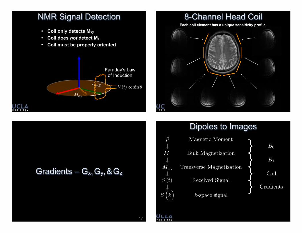
NMR Signal Detection• Coil only detects Mxy
• Coil does not detect Mz
• Coil must be properly oriented
Mxy
✓ V (t) / sin �
Faraday’s Law of Induction
R a d i o l o g y
8-Channel Head CoilEach coil element has a unique sensitivity profile.
Gradients – Gx, Gy, & Gz
17 R a d i o l o g y
µ Magnetic Moment }� B0 Mz Bulk Magnetization }� B1 Mxy Transverse Magnetization }� Coil
S (t) Received Signal }� GradientsS
� k⇥
k -space signal }� FFTI ( x) Image
Dipoles to Images

R a d i o l o g y
Gradients
• Gradients are a:– Small
• <5G/cm (<0.0075T @ edge of 30cm FOV)– Spatially varying
• Linear gradients• Adds to B0 only in Z-direction
– Time varying• Slewrate Max. ~150-200mT/m/ms
– Magnetic fields• Adds/Subtracts to the B0 field
– Parallel to B0
R a d i o l o g y
MRI InstrumentationY-Gradient
Transceiver
Patient
Z-Gradient
X-Gradient
http://www.magnet.fsu.edu
R a d i o l o g y
Z Gradients
B0
B0 � �B0
MaxwellPair Coil
I
I
B0 + �B0
R a d i o l o g y
Z-Gradients
Z
X
B0 + �B0
B0 � �B0
B0

R a d i o l o g y
X-Gradients
B0B0��B0 B0+�B0
Z
X
R a d i o l o g y
X+Z-Gradients
Z
X
Z
X
R a d i o l o g y
X+Z-Gradients
Spin IsochromatGroup of spins with the same resonance
frequency.
Possible Slice
Z
X
k-space
24
R a d i o l o g y
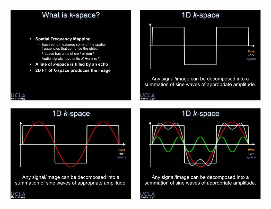
What is k-space?
• Spatial Frequency Mapping– Each echo measures some of the spatial
frequencies that comprise the object– k-space has units of cm-1 or mm-1
– Audio signals have units of Hertz (s-1)
• A line of k-space is filled by an echo• 2D FT of k-space produces the image
R a d i o l o g y
1D k-space
time-or-
space
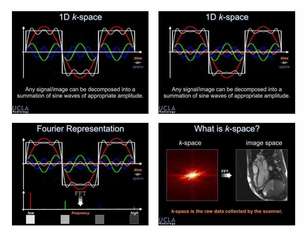
Any signal/image can be decomposed into a summation of sine waves of appropriate amplitude.
R a d i o l o g y
1D k-space
time-or-
space
Any signal/image can be decomposed into a summation of sine waves of appropriate amplitude.
R a d i o l o g y
1D k-space
time-or-
space
Any signal/image can be decomposed into a summation of sine waves of appropriate amplitude.
R a d i o l o g y
1D k-space
time-or-
space
Any signal/image can be decomposed into a summation of sine waves of appropriate amplitude.
R a d i o l o g y
1D k-space
time-or-
space
Any signal/image can be decomposed into a summation of sine waves of appropriate amplitude.
time-or-
space
Fourier Representation
low highfrequency
FFT➠R a d i o l o g y
What is k-space?
➠FFT
k-space image space
k-space is the raw data collected by the scanner.

R a d i o l o g y
What is k-space?
➠FFT
Contrast
➠FFT
Edges
Center
Edges
R a d i o l o g y
What is k-space?
ContrastInformation
Points in k-space represent different patterns in an image.
R a d i o l o g y
k-space spikes
➠FFT
k-space image space
A k-space spike creates a banding artifact.
R a d i o l o g y
k-space and Field of View
FFT➠
ky
kx
ky
kx FFT➠
Uniformly skipping lines in k-space causes aliasing.
FOV =1
�k

R a d i o l o g y
k-space and Resolution
FFT➠
ky
kx
ky
kx FFT➠
Acquiring fewer phase encodes decreases resolution.
Image Contrast
34
R a d i o l o g y
Why Image Contrast?Visual Area
of the Thalamus
Visual Cortex
Retina
Opticnerve
Optictract
Opticchiasm
The human visual system is more sensitive to contrast than absolute luminance.
R a d i o l o g y
Why Image Contrast?

Bloch Equations with Relaxation
DCVI
1952 Nobel Prize in Physics
Felix Bloch b. 23 Oct 1905 d. 10 Sep 1983
Edward Purcell b. 30 Sep 1912 d. 07 Mar 1997
“for their development of new methods for nuclear magnetic
precision measurements and discoveries in connection therewith“
DCVI
Bloch Equations
• Precession– Magnitude of unchanged– Phase (rotation) of changes due to
• Relaxation– T1 changes are slow O(100ms)– T2 changes are fast O(10ms)– Magnitude of M can be ZERO
• Diffusion– Spins are thermodynamically driven to
exchange positions.
{
Precession TransverseRelaxation
LongitudinalRelaxation
Diffusion
{ { {d~M
dt= ~M⇥ �~B� M
x
i +My
j
T2� (M
z
�M0) k
T1+Dr2 ~M
~M~B~M
R a d i o l o g y
Longitudinal & Transverse Relaxation
Mxy
(t) = M0xy
e�t/T2{Initial Condition
Return to Equilibrium
General solutions to the Bloch equations with relaxation in the rotating frame during free precession.
Mz (t) = M0z e
� tT1 +M0
⇣1� e�
tT1
⌘{ {
Initial Condition Return to Equilibrium

R a d i o l o g y
T1 & T2 RelaxationM0
A.U.
Time [ms]
M0xy
M0z
MzMxy
R a d i o l o g y
T1 and T2 Values @ 1.5T
Tissue T1 [ms] T2 [ms]
gray matter 925 100
white matter 790 92
muscle 875 47
fat 260 85
kidney 650 58
liver 500 43
CSF 2400 180
R a d i o l o g y
T1 Relaxation
• Longitudinal or spin-lattice relaxation• Typically, (10s ms)<T1< (100s ms)• T1 is long for
– Small molecules (water)– Large molecules (proteins)
• T1 is short for– Fats and intermediate-sized molecules
• T1 increases with increasing B0
• T1 decreases with contrast agents • Short T1s are bright on T1-weighted image
R a d i o l o g y
T1 Relaxation
0 1000 2000 3000 4000 5000
1.00
0.75
0.50
0.25
0.00
Fat – 260ms Liver – 500ms CSF – 2400ms
Decay Time [ms]
Fraction of M0

R a d i o l o g y
T2 Relaxation• Transverse or spin-spin relaxation
– Molecular interaction causes spin dephasing
• Typically, T2<(10s ms)• T2 increases with
– Decreasing molecular size• Large molecules have a short T2
– Fat has a short T2
– Increasing molecular mobility• Liquids have long T2s
– CSF, edema
– Decreasing molecular interactions• Solids have short T2s
• T2 relatively independent of B0
• T2 always < T1
• Long T2 is bright on T2 weighted imageR a d i o l o g y
T2 Relaxation
0 200 400 600 800
100
75
50
25
00
Liver – 43ms Fat – 85msCSF – 180ms
Decay Time [ms]
Percent Signal [a.u.]
R a d i o l o g y
T2* Relaxation
R a d i o l o g y
T2* Relaxation• The “observed” transverse relaxation time constant• Spin-spin (T2) dephasing combined with...
– Irreversible
• Intravoxel field inhomogeneity– B0
• Typically a few PPM over DSV (40-50cm)• 1PPM = 640Hz = 1.5µT
– Susceptibility differences (macro and micro)• Induce small field perturbations, therefore dephasing
– Reversible• Can be rephased with a spin echo
– Not with a gradient echo!
• Diffusion– Irreversible

R a d i o l o g y
T2* Relaxation
ReversibleLosses
IrreversibleLosses
1T ⇤
2
=1T2
+ ��B0
R a d i o l o g y
T2* Relaxation
ReversibleLosses
IrreversibleLosses
1
T ⇤2
=1
T2+
1
T02
R a d i o l o g y
T2* Relaxation
ReversibleLosses
IrreversibleLosses
1
T ⇤2
=1
T2+
1
T02
+1
TD2
+ · · ·
IrreversibleLosses
R a d i o l o g y
0 125 250 375 500
100
75
50
25
00
T2 – 125ms T2* – 90ms
Decay Time [ms]
Percent Signal [a.u.]
T2* vs T2
T2*<T2 (always!)
What are echoes?
48 R a d i o l o g y
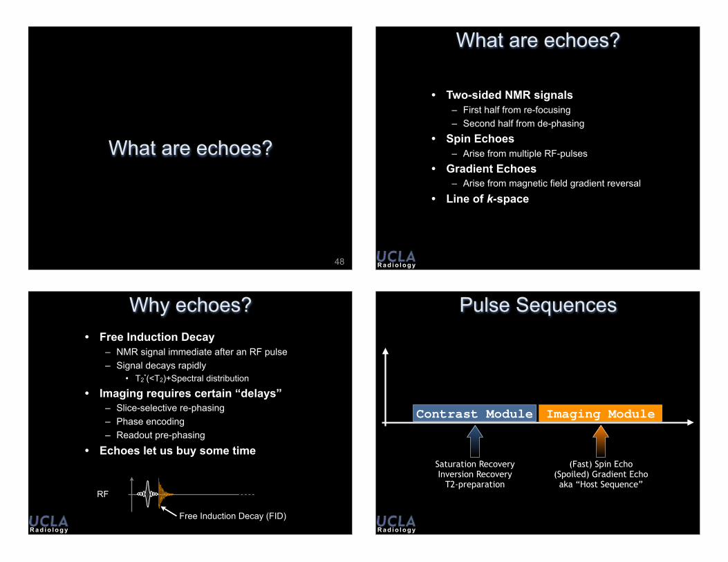
What are echoes?
• Two-sided NMR signals– First half from re-focusing– Second half from de-phasing
• Spin Echoes– Arise from multiple RF-pulses
• Gradient Echoes– Arise from magnetic field gradient reversal
• Line of k-space
R a d i o l o g y
Why echoes?• Free Induction Decay
– NMR signal immediate after an RF pulse– Signal decays rapidly
• T2*(<T2)+Spectral distribution
• Imaging requires certain “delays”– Slice-selective re-phasing– Phase encoding– Readout pre-phasing
• Echoes let us buy some time
RF
Free Induction Decay (FID)R a d i o l o g y
Pulse Sequences
Contrast Module Imaging Module
Saturation RecoveryInversion Recovery
T2-preparation
(Fast) Spin Echo(Spoiled) Gradient Echoaka “Host Sequence”

R a d i o l o g y
Pulse Sequence Definitions
• TR - Repetition Time– Duration of basic pulse sequence repeating block– At least one echo acquired per TR
• TE - Echo Time– Time from excitation to the maximum of the echo
Spin Echo Imaging
51
R a d i o l o g y
Spin Echo
• Advantages– All spins within voxel rephased
• Insensitive to off-resonance– B0 inhomogeneity– Intravoxel Chemical shift signal loss– Susceptibility
– Great for T1, T2, ρ contrast• Not T2*
– High SNR
• Disadvantages– TR can be long– SAR can be high
R a d i o l o g y
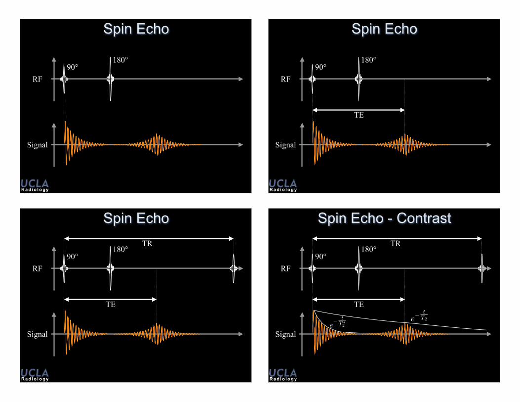
Spin Echo
RF
Signal
90°
Some T2* signal losses are reversible.
R a d i o l o g y
Spin Echo
RF
Signal
90°180°
R a d i o l o g y
Spin Echo
TE
RF
Signal
90°180°
R a d i o l o g y
Spin EchoTR
TE
RF
Signal
90°180°
R a d i o l o g y
Spin Echo - ContrastTR
TE
RF
Signal
90°180°
e� t
T⇤2
e� t
T2
R a d i o l o g y
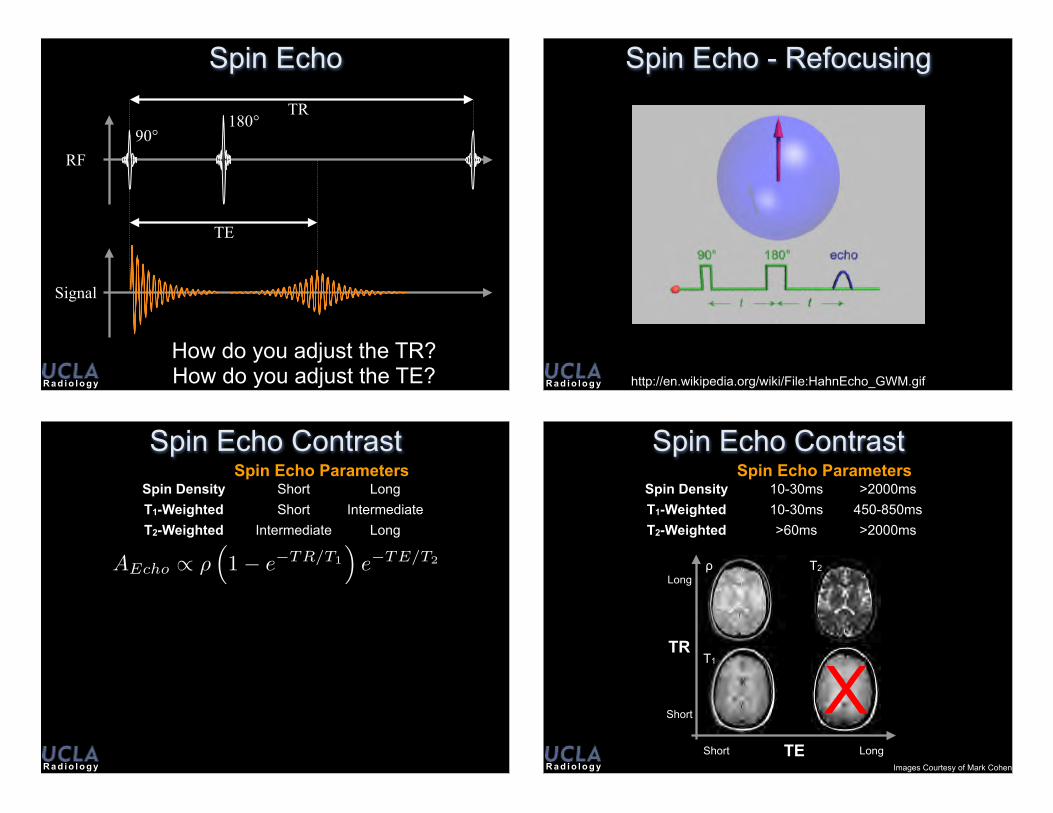
Spin EchoTR
TE
RF
Signal
90°180°
How do you adjust the TR?How do you adjust the TE? R a d i o l o g y
Spin Echo - Refocusing
http://en.wikipedia.org/wiki/File:HahnEcho_GWM.gif
R a d i o l o g y
Spin Echo ContrastSpin Density Short LongT1-Weighted Short IntermediateT2-Weighted Intermediate Long
Spin Echo Parameters
AEcho
/ ⇢⇣1� e�TR/T1
⌘e�TE/T2
R a d i o l o g y
Spin Echo ContrastSpin Density 10-30ms >2000msT1-Weighted 10-30ms 450-850msT2-Weighted >60ms >2000ms
Spin Echo Parameters
Images Courtesy of Mark Cohen
TR
Short
Long
TEShort Long
T2
T1
ρ
X

R a d i o l o g y
Spin Echo - Contrast
http://en.wikipedia.org/wiki/File:HahnEcho_GWM.gif R a d i o l o g y
Spin Echo - Variable TE T2 Contrast
TE=13ms TE=26ms TE=53ms
TE=106ms TE=145ms TE=172ms
R a d i o l o g y
Echo-3
Fast Spin Echo90°
180°
RF
GSlice
GPhase
GReadout
Signal
180° 180°
T2-decay
Echo-2Echo-1
R a d i o l o g y
Fast Spin Echo• Advantages
– Turbo factor accelerates imaging– Can be used with 2D slice interleaving– Allows T2 weighted imaging in a breath hold
• Disadvantages– High turbo factors (ETL>4):
• Blur images• Alter image contrast
– Fat & Water are both bright on T2-weighted• Water/CSF T2 is long• Repeated 180s reduce spin-spin interaction
– This lengthens the moderate T2 of fat
– SAR can be high
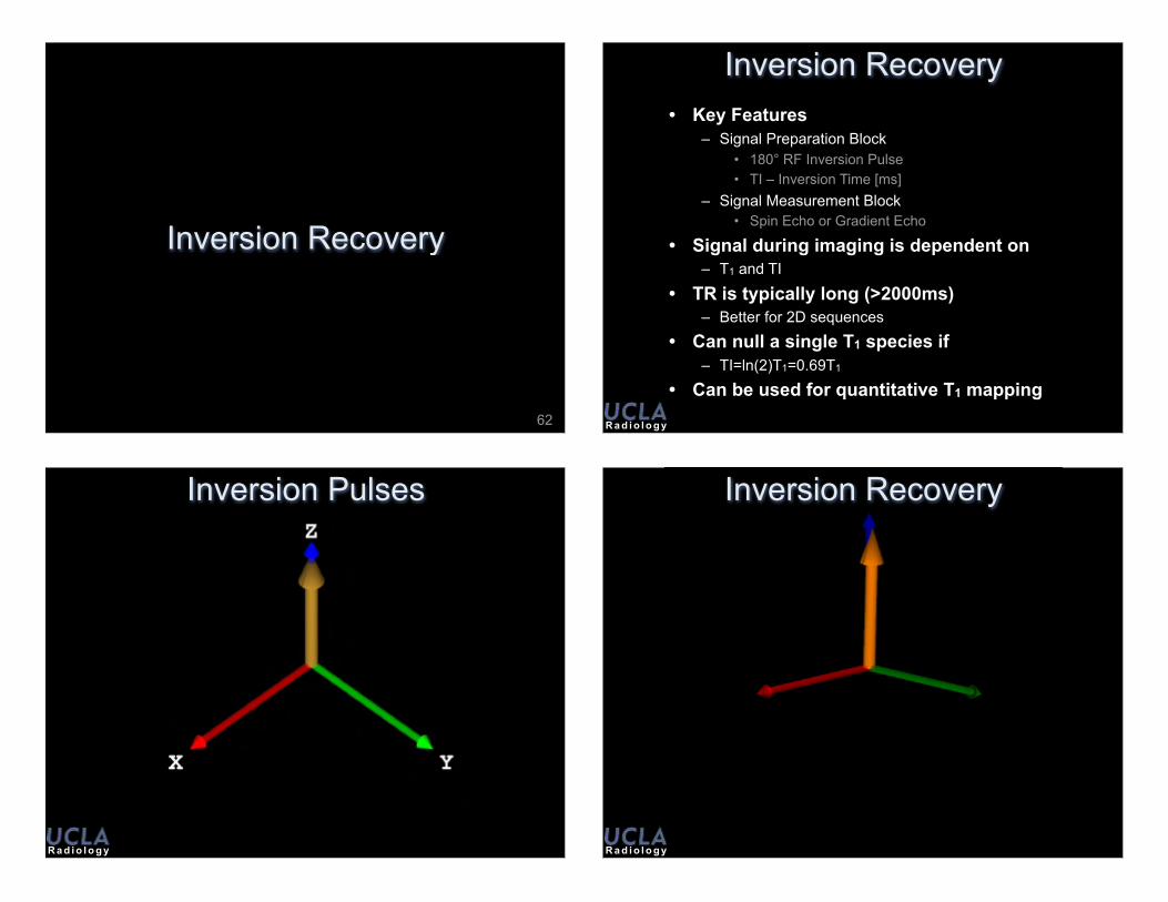
Inversion Recovery
62 R a d i o l o g y
Inversion Recovery• Key Features
– Signal Preparation Block• 180° RF Inversion Pulse• TI – Inversion Time [ms]
– Signal Measurement Block• Spin Echo or Gradient Echo
• Signal during imaging is dependent on– T1 and TI
• TR is typically long (>2000ms)– Better for 2D sequences
• Can null a single T1 species if– TI=ln(2)T1=0.69T1
• Can be used for quantitative T1 mapping
R a d i o l o g y
Inversion Pulses
R a d i o l o g y
Inversion Recovery
R a d i o l o g y
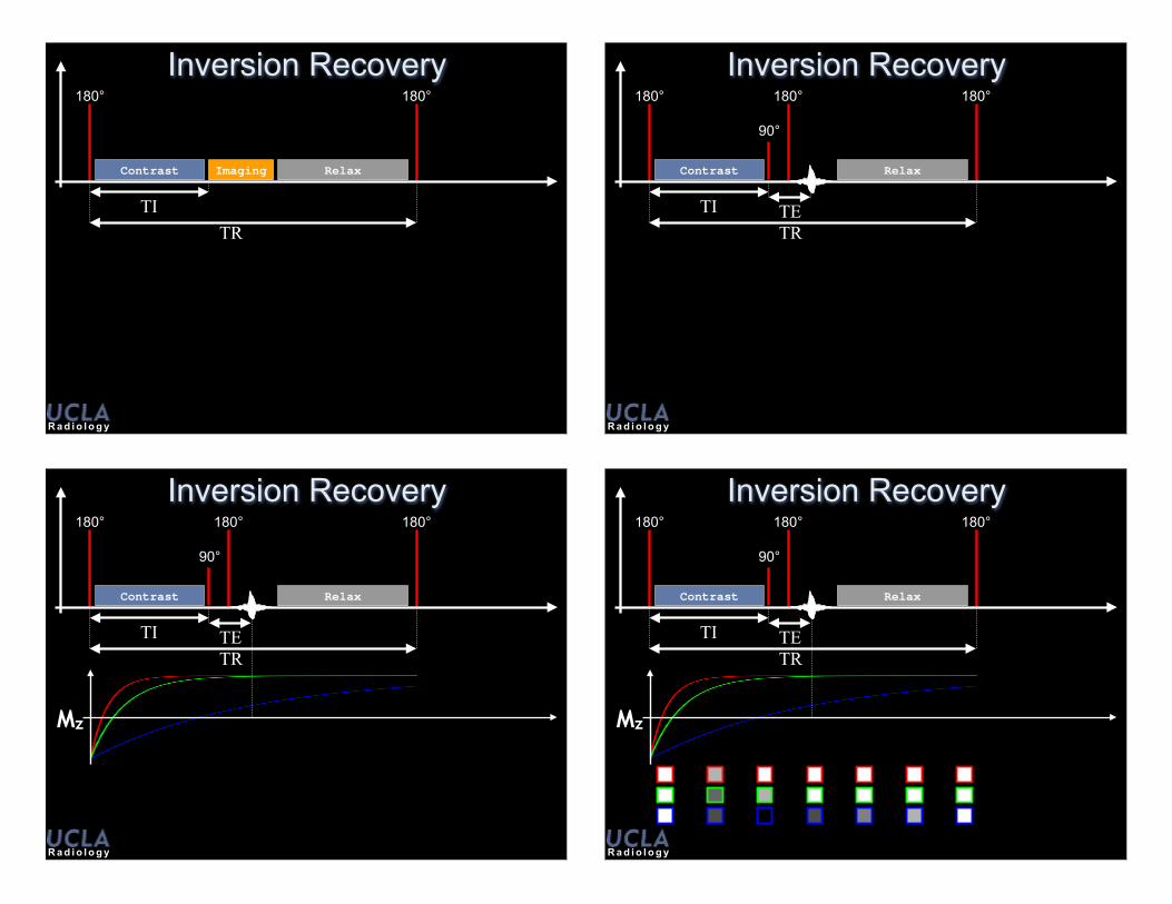
180°
Inversion Recovery
Contrast
180°
ContrastRelaxImaging
TITR
R a d i o l o g y
180°
Inversion Recovery
TE
180°
90°
180°
Contrast
TRTI
Relax Contrast
R a d i o l o g y
180°
Inversion Recovery180°
90°
180°
TRTI
Mz
Contrast Relax
TE
Contrast
R a d i o l o g y
180°
Inversion Recovery180°
90°
180°
TRTI
Mz
Contrast Relax
TE
Contrast

Gradient Echo Imaging
68 R a d i o l o g y
Basic Gradient Echo Sequence
RF
Slice Select
PhaseEncode
Freq.Encode
Free Induction Decay (FID)
e� t
T⇤2
R a d i o l o g y
Basic Gradient Echo Sequence
RF
Slice Select
PhaseEncode
Freq.Encode
Free Induction Decay (FID)
R a d i o l o g y
Basic Gradient Echo Sequence
RF
Slice Select
PhaseEncode
Freq.Encode
Gradient Echo!
e� t
T⇤2

R a d i o l o g y
Basic Gradient Echo Sequence
RF
Slice Select
PhaseEncode
Freq.Encode
TETR
R a d i o l o g y
WastedTime
Basic Gradient Echo Sequence
RF
Slice Select
PhaseEncode
Freq.Encode
TETR
R a d i o l o g y
Gradient Echo + Spoiling
RF
Slice Select
PhaseEncode
Freq.Encode
SpoilerGradient
RF PhaseCycling
SpoilerGradient
Gradient Echoes & Contrast
R a d i o l o g y
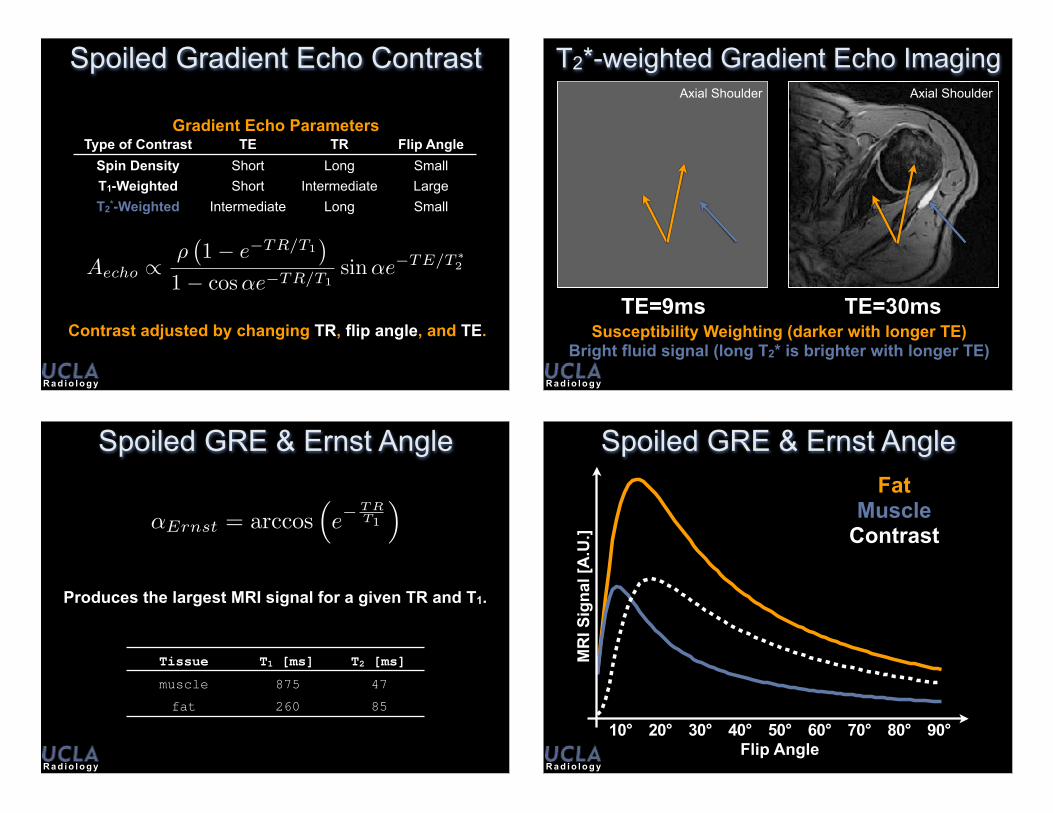
Spoiled Gradient Echo Contrast
Aecho
/⇢
�1� e�TR/T1
�
1� cos ↵e�TR/T1sin ↵e�TE/T
⇤2
Contrast adjusted by changing TR, flip angle, and TE.
Type of Contrast TE TR Flip AngleSpin Density Short Long SmallT1-Weighted Short Intermediate LargeT2*-Weighted Intermediate Long Small
Gradient Echo Parameters
R a d i o l o g y
T2*-weighted Gradient Echo Imaging
TE=9ms TE=30msSusceptibility Weighting (darker with longer TE)
Bright fluid signal (long T2* is brighter with longer TE)
Axial Shoulder Axial Shoulder
R a d i o l o g y
Spoiled GRE & Ernst Angle
�Ernst = arccos�e�
T RT1
⇥
Tissue T1 [ms] T2 [ms]
muscle 875 47fat 260 85
Produces the largest MRI signal for a given TR and T1.
R a d i o l o g y
Spoiled GRE & Ernst Angle
10° 20° 30° 40° 50° 60° 70° 80° 90°Flip Angle
MR
I Sig
nal [
A.U
.]
FatMuscle
Contrast

R a d i o l o g y
Spoiled GRE & Ernst Angle
1° 5° 10° 20°
30° 45° 60° 90°
High Muscle Signal High Fat Signal
Highest Contrast
R a d i o l o g y
Spin Echo EPI90°
180°
RF
GSlice
GPhase
GReadout
Signal
TE
90°
TR
T2*-decay
Off Resonance Effects Accumulate
R a d i o l o g y
Spin Echo EPI• Advantages
– Can acquire data in a “single shot”– Can be used with 2D slice interleaving– Allows fast T2* weighted imaging
• Disadvantages– Single Shot EPI
• Ghosting • Blur images• Image distortion• Alter image contrast
– Multi-shot EPI• Slower than single shot
– Faster than SE
• Applications– DWI, Perfusion, fMRI
R a d i o l o g y
µ Magnetic Moment }� B0 Mz Bulk Magnetization }� B1 Mxy Transverse Magnetization }� Coil
S (t) Received Signal }� GradientsS
� k⇥
k -space signal }� FFTI ( x) Image
Dipoles to Images

UCLA – Radiology – DCVI
Daniel B. Ennis, [email protected] (Office)http://ennis.bol.ucla.edu
Peter V. Ueberroth Bldg.Suite 1417, Room C10945 Le Conte Avenue
Thanks