introduction to layout control with jmri/panelpro to ctc-2.pdf · ctc logix logix the ctc panel...
TRANSCRIPT
Create a Detailed CTC MachineModel with JMRI/PanelPro
Other Clinics in this series: Introduction to Layout Control with JMRI/PanelPro
8:30 PM, Sunday, July 13th
Add Signals to your Layout with JMRI/PanelPro10:00 PM, Sunday, July 13th
Introduction to Layout Control with JMRI/PanelProRepeated 4:00 PM, Friday, July 18th
Dick Bronson - R R -C irK its, Inc.
CTC Logix
Logix The CTC panel that we have just covered is
controlled by JMRI Logix rather than a cabinet full of relays like the prototype.

CTC Logix
Logix The CTC panel that we have just covered is
controlled by JMRI Logix rather than a cabinet full of relays like the prototype.

CTC Logix
Logix The CTC panel that we have just covered is
controlled by JMRI Logix rather than a cabinet full of relays like the prototype.
Remember that the CTC panel and its equipment are acting as a over ride controlling interface for the basic ABS system that is located in the trackside signal control boxes.
Commands are sent back and forth between the plant and the CTC system via a pulse width encoding system.
The prototype used one line to send and receive all information for each of the plants under its control.

CTC Logix
Logix The coded commands actually were sent quite
slowly and one at a time. We will simulate the delays and relay sounds, but not the fact that each command had to be queued before it was sent. This may cause overlapping relay sounds in our simulation that were not heard in the original panels.
CTC Logix
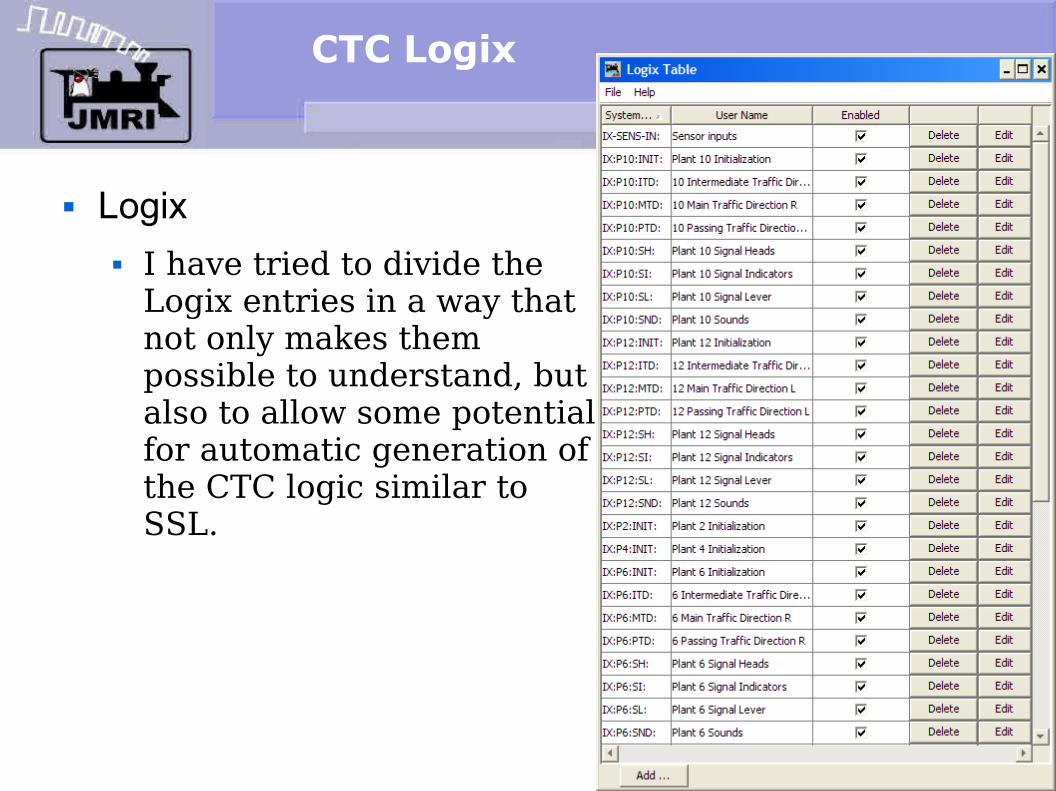
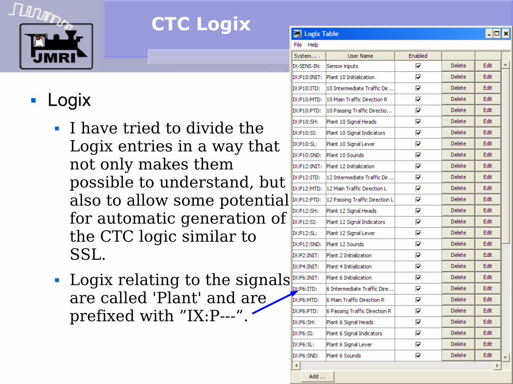
Logix I have tried to divide the
Logix entries in a way that not only makes them possible to understand, but also to allow some potential for automatic generation of the CTC logic similar to SSL.
CTC Logix
Logix I have tried to divide the
Logix entries in a way that not only makes them possible to understand, but also to allow some potential for automatic generation of the CTC logic similar to SSL.
Logix relating to the signals are called 'Plant' and are prefixed with ”IX:P---”.
CTC Logix
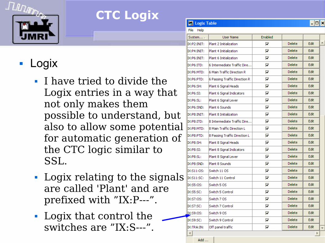
Logix I have tried to divide the
Logix entries in a way that not only makes them possible to understand, but also to allow some potential for automatic generation of the CTC logic similar to SSL.
Logix relating to the signals are called 'Plant' and are prefixed with ”IX:P---”.
Logix that control the switches are ”IX:S---”.
CTC Logix
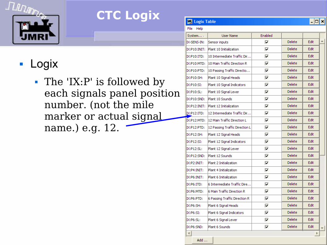
Logix The 'IX:P' is followed by
each signals panel position number. (not the mile marker or actual signal name.) e.g. 12.

CTC Logix
Logix The 'IX:P' is followed by
each signals panel position number. (not the mile marker or actual signal name.) e.g. 12.
In like manner the switches are identified by their panel location. e.g. 5.
CTC Logix
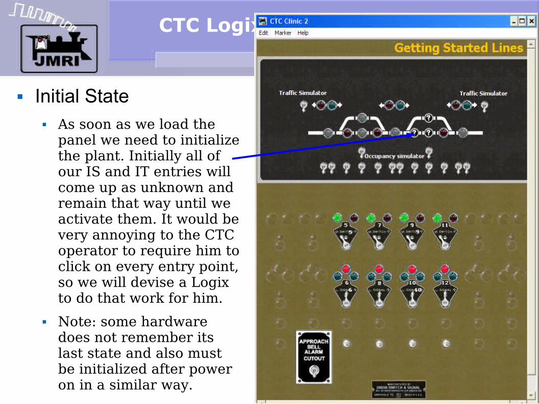
Initial State As soon as we load the
panel we need to initialize the plant. Initially all of our IS and IT entries will come up as unknown and remain that way until we activate them. It would be very annoying to the CTC operator to require him to click on every entry point, so we will devise a Logix to do that work for him.
Note: some hardware does not remember its last state and also must be initialized after power on in a similar way.

CTC Logix
Conditionals First we initialize
each plant.

CTC Logix
Conditionals First we initialize
each plant. Each plant has its
own initialization because a large panel would have too many actions to fit in one operation.
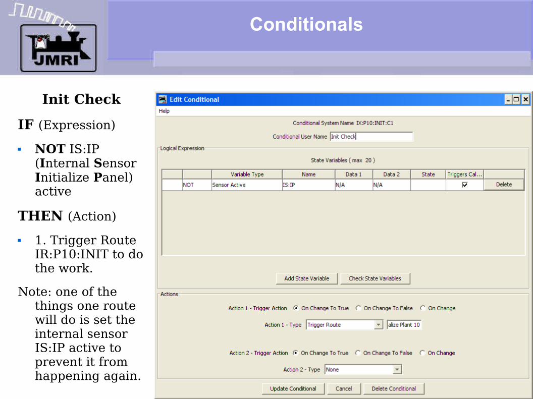
Conditionals
Init CheckIF (Expression) NOT IS:IP
(Internal Sensor Initialize Panel) active
THEN (Action) 1. Trigger Route
IR:P10:INIT to do the work.
Note: one of the things one route will do is set the internal sensor IS:IP active to prevent it from happening again.

CTC Logix
Routes The route initializes
the turnout that is part of this plant.
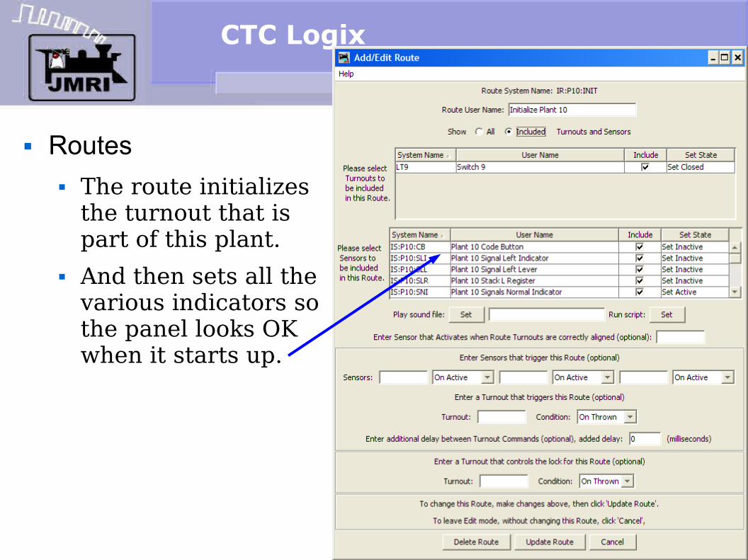
CTC Logix
Routes The route initializes
the turnout that is part of this plant.
And then sets all the various indicators so the panel looks OK when it starts up.
CTC Logix
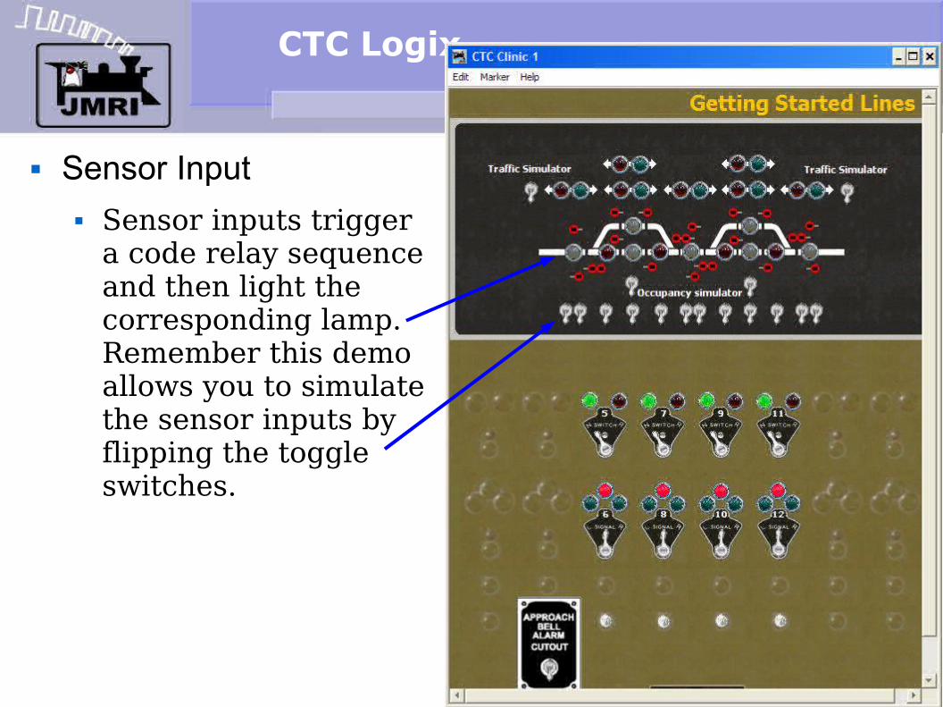
Sensor Input Sensor inputs trigger
a code relay sequence and then light the corresponding lamp. Remember this demo allows you to simulate the sensor inputs by flipping the toggle switches.

CTC Logix
Sensor Input Sensor inputs trigger
a code relay sequence and then light the corresponding lamp. Remember this demo allows you to simulate the sensor inputs by flipping the toggle switches.
We are simulating two intermediate blocks. The CTC indication shows them all as one lamp.
CTC Logix
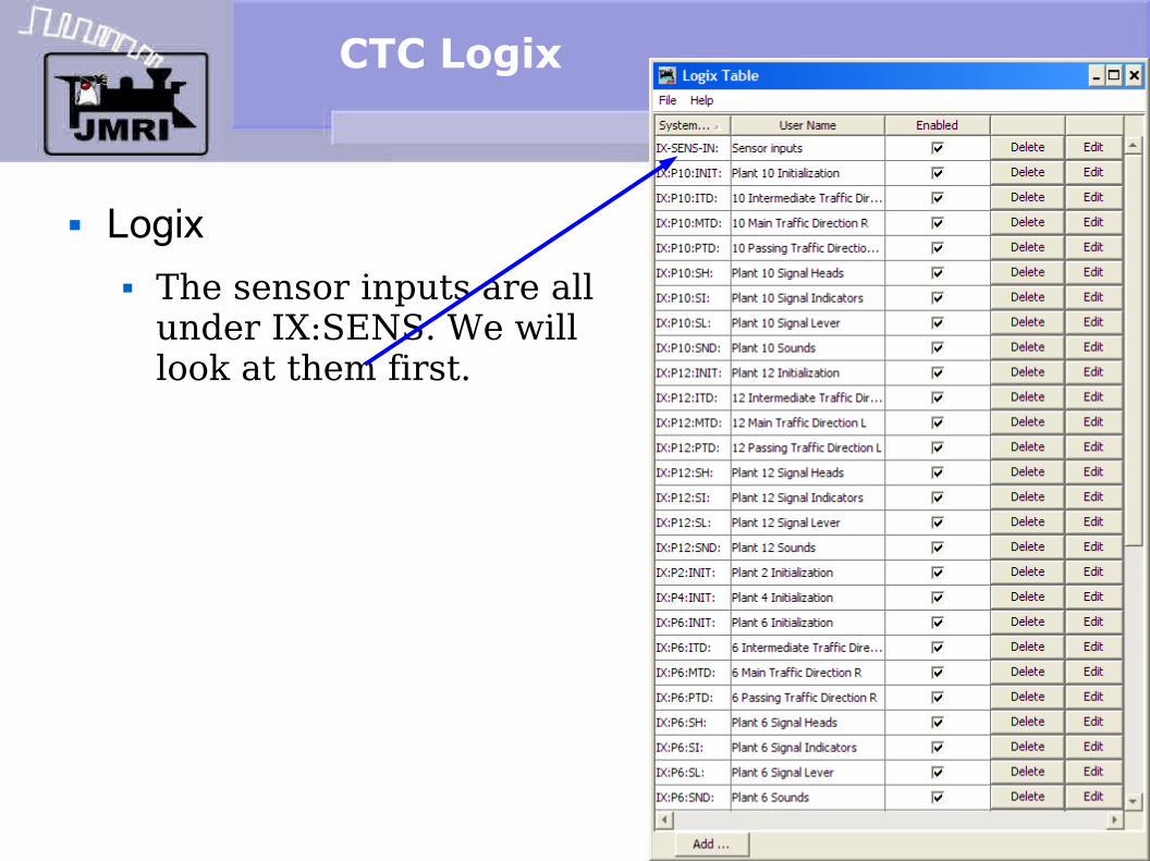
Logix The sensor inputs are all
under IX:SENS. We will look at them first.

CTC Logix
Logix The sensor inputs are all
under IX:SENS. We will look at them first.
Click 'Edit' to open the list of conditionals.
CTC Logix
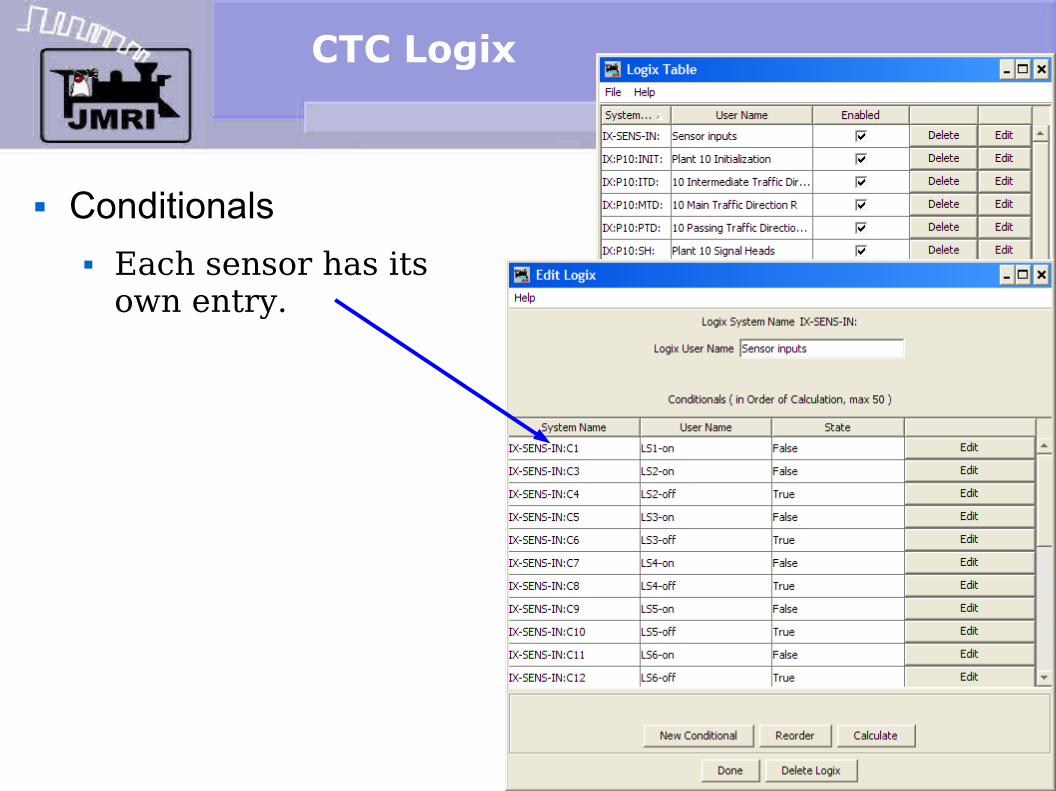
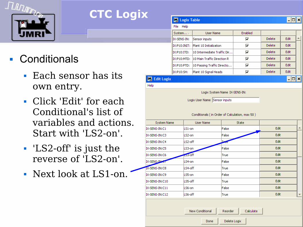
Conditionals Each sensor has its
own entry.
CTC Logix
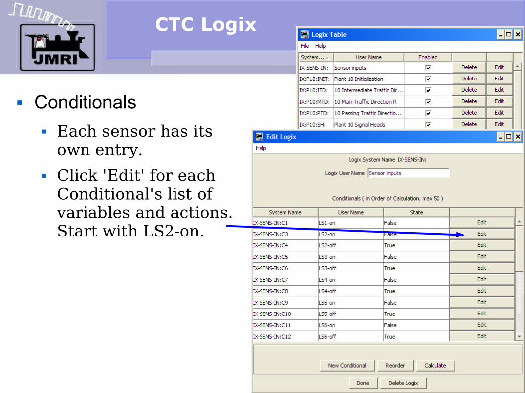
Conditionals Each sensor has its
own entry. Click 'Edit' for each
Conditional's list of variables and actions. Start with LS2-on.
Conditionals
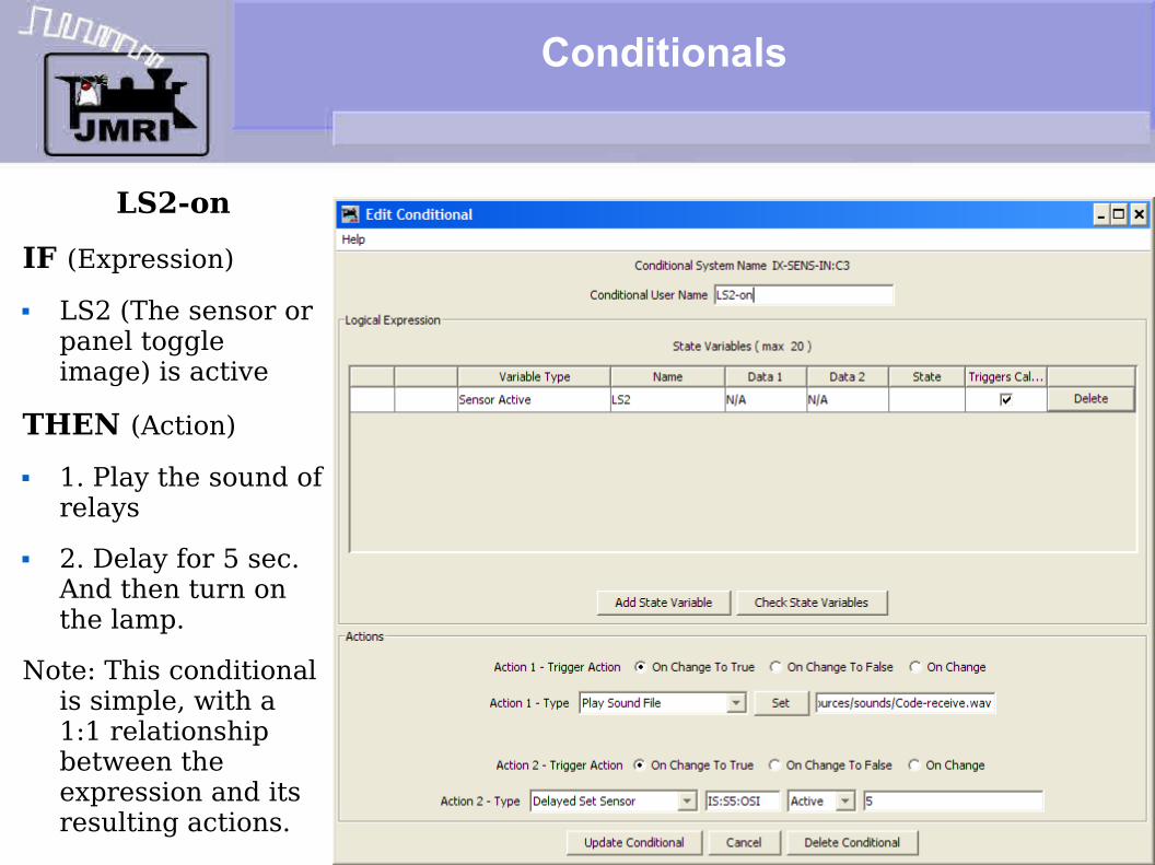
LS2-onIF (Expression) LS2 (The sensor or
panel toggle image) is active
THEN (Action) 1. Play the sound of
relays 2. Delay for 5 sec.
And then turn on the lamp.
Note: This conditional is simple, with a 1:1 relationship between the expression and its resulting actions.
CTC Logix
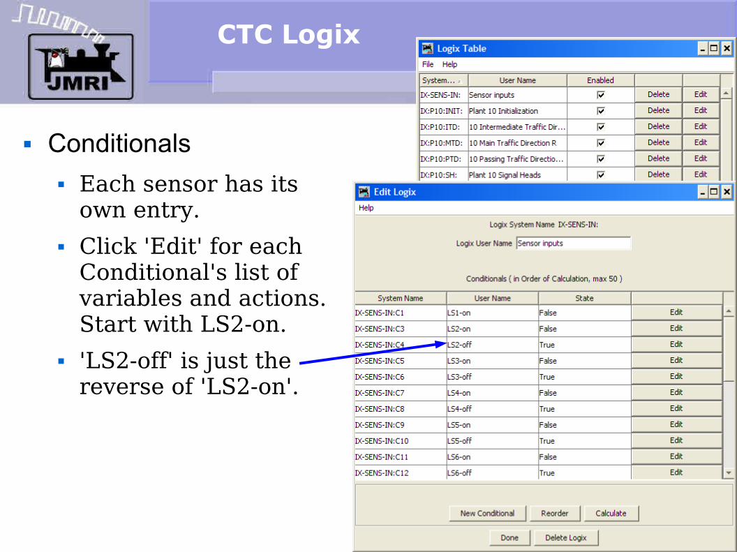
Conditionals Each sensor has its
own entry. Click 'Edit' for each
Conditional's list of variables and actions. Start with LS2-on.
'LS2-off' is just the reverse of 'LS2-on'.
CTC Logix
Conditionals Each sensor has its
own entry. Click 'Edit' for each
Conditional's list of variables and actions. Start with 'LS2-on'.
'LS2-off' is just the reverse of 'LS2-on'.
Next look at LS1-on.

Conditionals
LS1-on We are now watching
the state of the first two blocks which form an intermediate block. If neither sensor is active, and then either one becomes active, we will play the relay sound, delay for 5 seconds while the sound plays, and then turn on the lamp.
Long sections of single track are often formed of several blocks, each with their own signals. The CTC machine only shows the operator that one or more of these blocks is occupied.

Conditionals
LS1-onIF (Expression) LS1 (The sensor
or panel toggle image) is active
LS4 is NOT already active
THEN (Action) 1. Play the sound
of relays 2. Delay for 5
sec. And then turn on the lamp.

CTC Logix
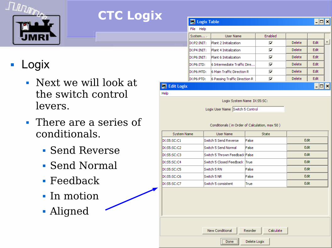
Logix Next we will look at
the switch control levers.

CTC Logix
Logix Next we will look at
the switch control levers.
There are a series of conditionals. Send Reverse
Conditionals
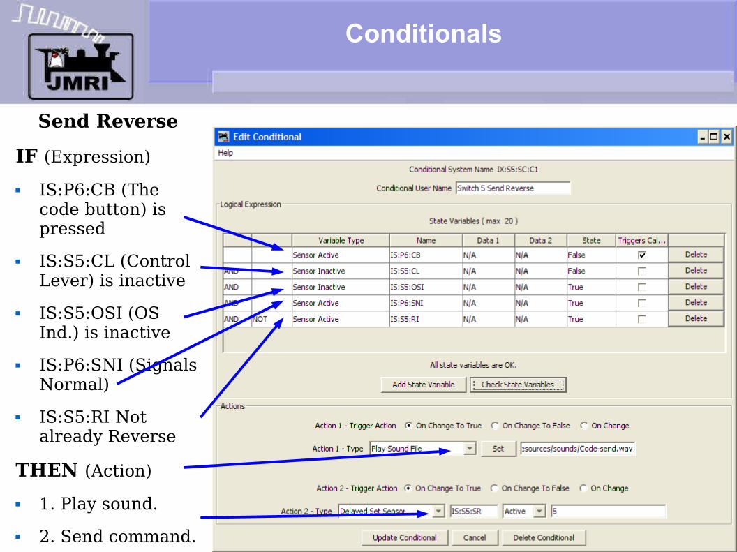
Send ReverseIF (Expression) IS:P6:CB (The
code button) is pressed
IS:S5:CL (Control Lever) is inactive
IS:S5:OSI (OS Ind.) is inactive
IS:P6:SNI (Signals Normal)
IS:S5:RI Not already Reverse
THEN (Action) 1. Play sound. 2. Send command.

CTC Logix
Logix Next we will look at
the switch control levers.
There are a series of conditionals. Send Reverse Send Normal

Conditionals
Send NormalIF (Expression) IS:P6:CB (The
code button) is pressed
IS:S5:CL (Control Lever) is active
IS:S5:OSI (OS Ind.) is inactive
IS:P6:SNI (Signals Normal)
IS:S5:NI Not already Normal
THEN (Action) 1. Play sound. 2. Send command.

CTC Logix
Logix Next we will look at
the switch control levers.
There are a series of conditionals. Send Reverse Send Normal Feedback

Conditionals
Rev FeedbackIF (Expression) LT5 (The turnout
has moved)
THEN (Action) 1. Delay and then
send command to set the indication.
2. Play sound.Note: the two actions
are performed immediately. The sound does not wait for the delay to complete. The result is, you hear the sound, then the lamp changes.

CTC Logix
Logix Next we will look at
the switch control levers.
There are a series of conditionals. Send Reverse Send Normal Feedback In motion
Conditionals
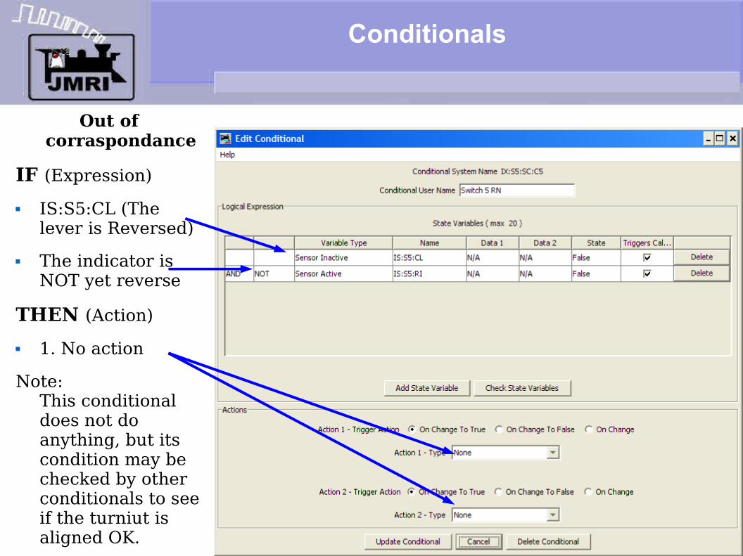
Out of corraspondance
IF (Expression) IS:S5:CL (The
lever is Reversed) The indicator is
NOT yet reverse
THEN (Action) 1. No actionNote:
This conditional does not do anything, but its condition may be checked by other conditionals to see if the turniut is aligned OK.
CTC Logix
Logix Next we will look at
the switch control levers.
There are a series of conditionals. Send Reverse Send Normal Feedback In motion Aligned
Conditionals
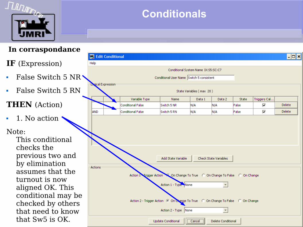
In corraspondance
IF (Expression) False Switch 5 NR False Switch 5 RN
THEN (Action) 1. No actionNote:
This conditional checks the previous two and by elimination assumes that the turnout is now aligned OK. This conditional may be checked by others that need to know that Sw5 is OK.

CTC Logix
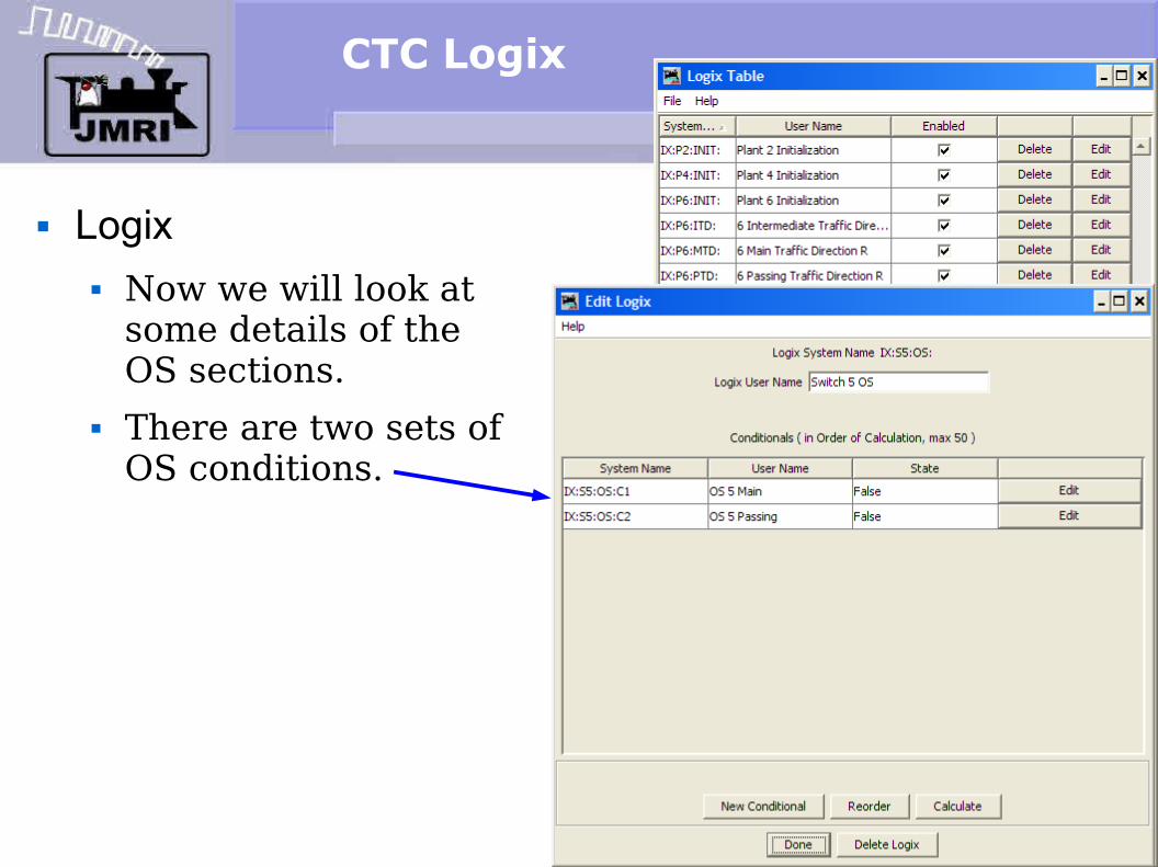
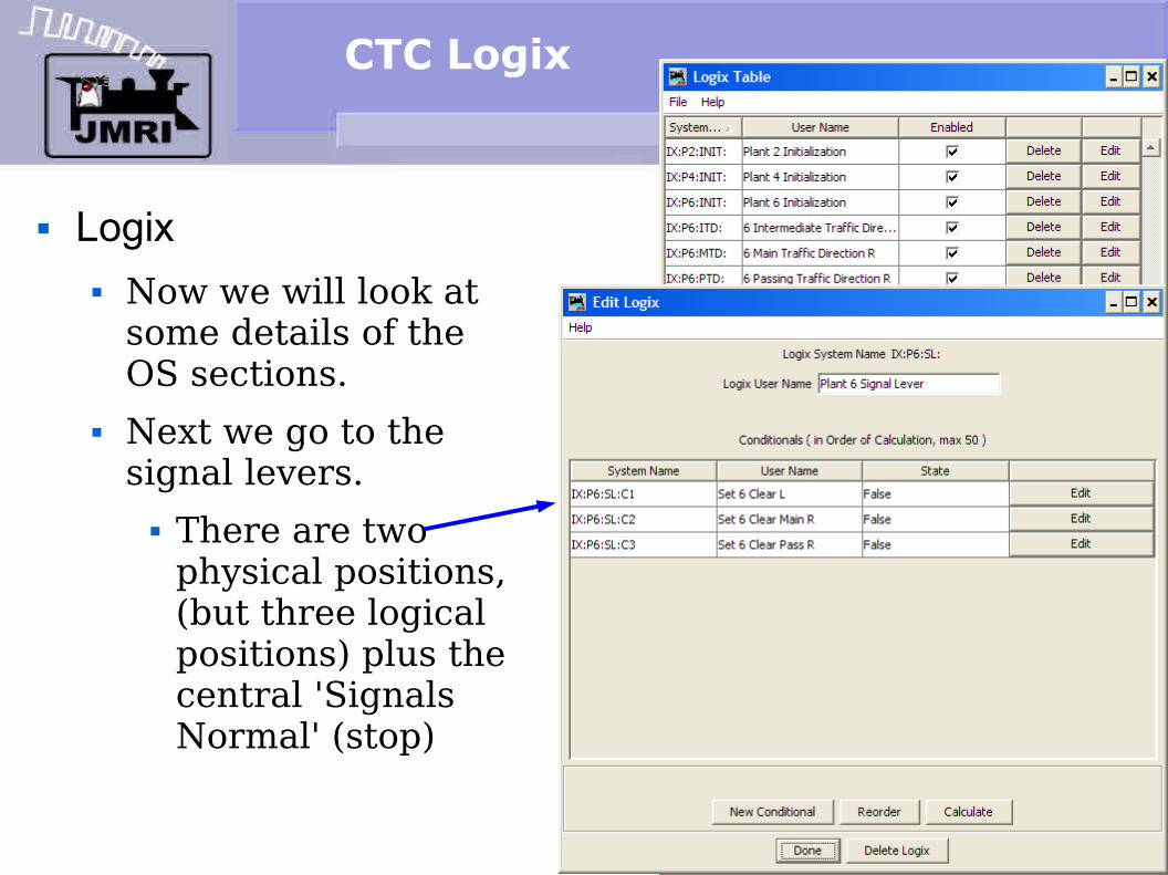
Logix Now we will look at
some details of the OS sections.
CTC Logix
Logix Now we will look at
some details of the OS sections.
There are two sets of OS conditions.

Logix
There are two OS conditionals, Main and Passing. At first glance 'OS occupied' seems like a simple concept.
Things get more complex in real life. If you are on the single track (intermediate track) then the OS is always considered part of the single track block for occupancy. I.e. the single track is not clear until the adjacent OS is also clear.
However, if you are on the main or passing sidings, then things are more complex. The OS is only considered to be a part of the block when the turnout is aligned to include the OS. I.e. If a train is on the OS it only 'occupies' the block/s that the OS turnout aligns with. It does not occupy the other siding.
This is because a 'block' includes all the track between a signal and the next opposing signal, but the OS itself is interspaced between the two sets of signals.
Conditionals
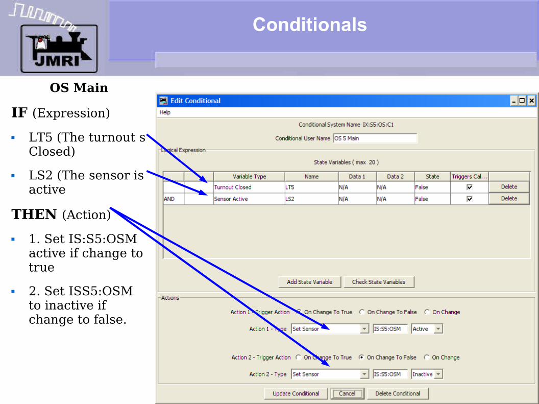
OS Main
IF (Expression) LT5 (The turnout s
Closed) LS2 (The sensor is
active
THEN (Action) 1. Set IS:S5:OSM
active if change to true
2. Set ISS5:OSM to inactive if change to false.
CTC Logix
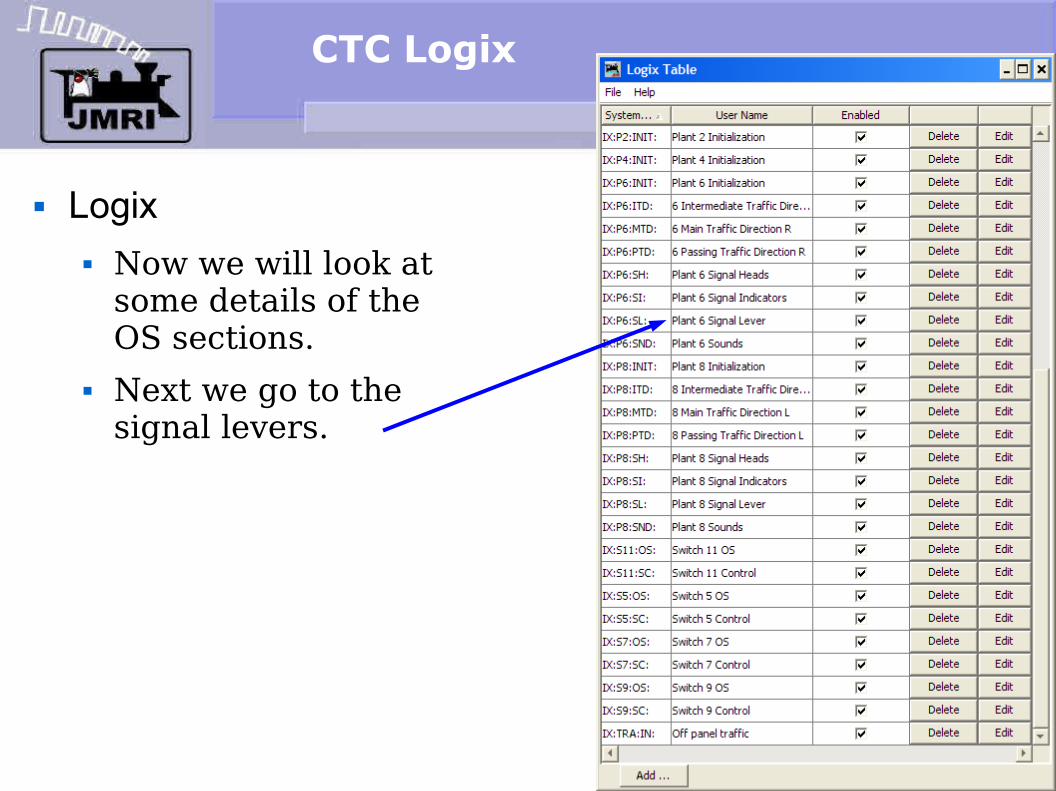
Logix Now we will look at
some details of the OS sections.
Next we go to the signal levers.
CTC Logix
Logix Now we will look at
some details of the OS sections.
Next we go to the signal levers. There are two
physical positions, (but three logical positions) plus the central 'Signals Normal' (stop)
Conditionals
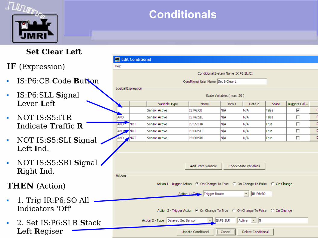
Set Clear Left
IF (Expression) IS:P6:CB Code Button IS:P6:SLL Signal
Lever Left NOT IS:S5:ITR
Indicate Traffic R NOT IS:S5:SLI Signal
Left Ind. NOT IS:S5:SRI Signal
Right Ind.
THEN (Action) 1. Trig IR:P6:SO All
Indicators 'Off' 2. Set IS:P6:SLR Stack
Left Regiser

Logix
Stacking Trains (Follow-on traffic) CTC allows the operator to send multiple trains into the same
single track as long as they are following one another. He really has no way to tell how far any train has progressed becaue the underlying ABS is controlling the train spacing. Once a train enters the OS, the signals normal light comes on. (and the OS bell rings, if it is not cut off)
Once the OS has cleared, the operator may allow another train to follow the first, by realigning the switch, if necessary, and then pressing the code button once again. The signals normal will go off as before, but all traffic indicators will remain off until the original train has proceeded far enough to let the ABS clear (Usually to approach) the head block single track signal, which allows the next train to proceed. At that point a directional 'clear' indicator will light again, letting the operator know the next train may follow the first. When the following train enters the OS the OS bell will sound again, etc.

CTC Logix
Logix Now we will look at
some details of the OS sections.
Next we go to the signal levers.
Then Signal Indicators

CTC Logix
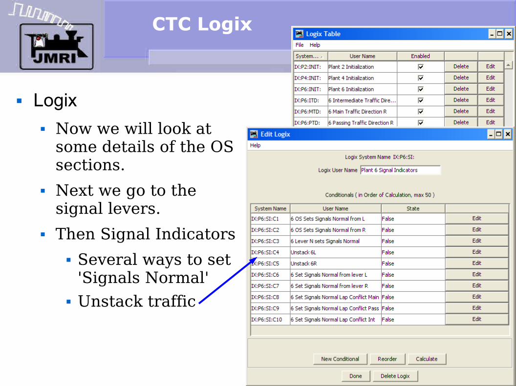
Logix Now we will look at
some details of the OS sections.
Next we go to the signal levers.
Then Signal Indicators Several ways to set
'Signals Normal'
Conditionals
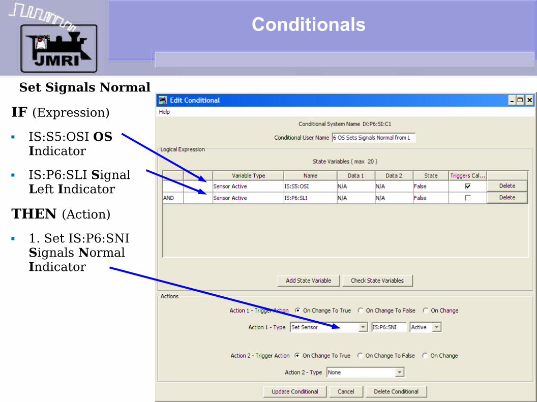
Set Signals Normal
IF (Expression) IS:S5:OSI OS
Indicator IS:P6:SLI Signal
Left Indicator
THEN (Action) 1. Set IS:P6:SNI
Signals Normal Indicator
Conditionals
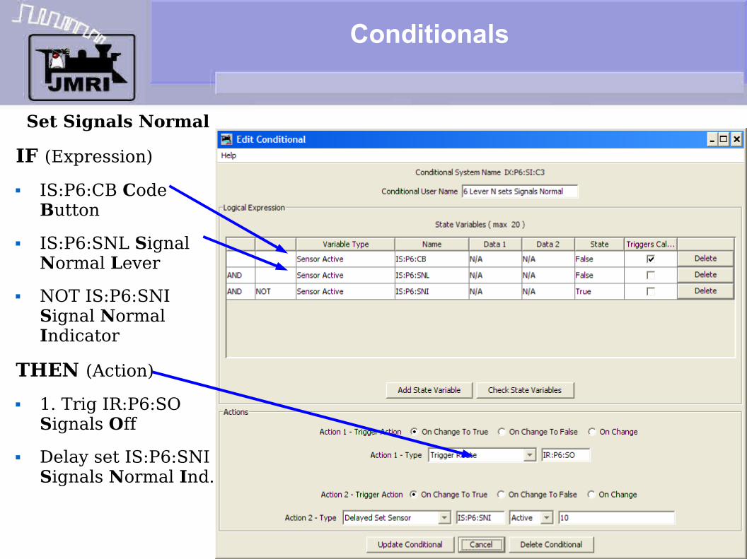
Set Signals Normal
IF (Expression) IS:P6:CB Code
Button IS:P6:SNL Signal
Normal Lever NOT IS:P6:SNI
Signal Normal Indicator
THEN (Action) 1. Trig IR:P6:SO
Signals Off Delay set IS:P6:SNI
Signals Normal Ind.
Logix
Setting Signals Normal with the lever.This is one operation that will get you negative comments. It
means you changed your mind about an action, and are about to drop a stop signal in the face of a moving train. The prototype will impose a long delay at this point to allow the train to proceed to the next signal (in case he already passed the signal you just dropped to red) and also time enough for him to stop when he sees the next red. (possibly running past it)
Only after the delay has timed out will the 'Signals Normal' indicator light again and allow for any changes in turnout position or traffic direction, and then only if the any trains are safely stopped short of the OS.
Prototype delays can be from 2-10 minutes. We used 10 seconds here. Modelers would not put up with a prototypical delay without spending the time forming a lynch mob for the dispatcher.
CTC Logix
Logix Now we will look at
some details of the OS sections.
Next we go to the signal levers.
Then Signal Indicators Several ways to set
'Signals Normal' Unstack traffic

Conditionals
Unstack 6 Left
IF (Expression) IS:P6:SLR Stack
Left Register IS:S5:OSI OS
Indicator IX:S5:SC:C7 Switch
Control (Consistent) NOT LS1 (block)
THEN (Action) 1. Set IS:P6:SLI
Signals Left Indicator
2. Delay set inactive IS:P6:SLR Stack Left Register
CTC Logix
Logix Now we will look at
some details of the OS sections.
Next we go to the signal levers.
Then Signal Indicators Several ways to set
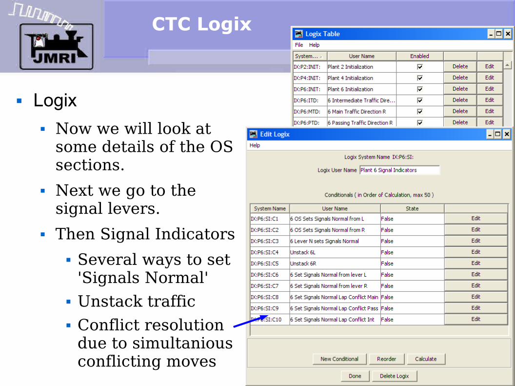
'Signals Normal' Unstack traffic Conflict resolution
due to simultanious conflicting moves

Logix
Conflicting moves (overlaped traffic direction)It is possible to setup conflicting moves on a CTC machine,
especially with boundry traffic where both operators may simultaniously choose to send opposing traffic on the single track that joins two districts. The code traffic delays involved leave a gap between the sending of a signal and the registering of that information in the next CTC machine.
This conflict resolution Logix immediately detects these conflicts once they appear, and restors all the signals to stop, and then imposes a timout delay for any traffic that has responded to the brief signal flash.
A single operator should not setup traffic that conflicts with himself. Phone or radio communications with adjoining districts should prevent these conflicts in the first place. In either case the machine detects the errors and locks the signals back to stop long enough to resolve them.

CTC Logix
Logix Now we will look at
some details of the OS sections.
Next we go to the signal levers.
Then Signal Indicators Finally Signal Heads
CTC Logix
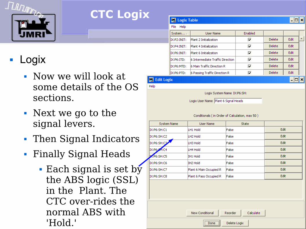
Logix Now we will look at
some details of the OS sections.
Next we go to the signal levers.
Then Signal Indicators Finally Signal Heads
Each signal is set by the ABS logic (SSL) in the Plant. The CTC over-rides the normal ABS with 'Hold.'
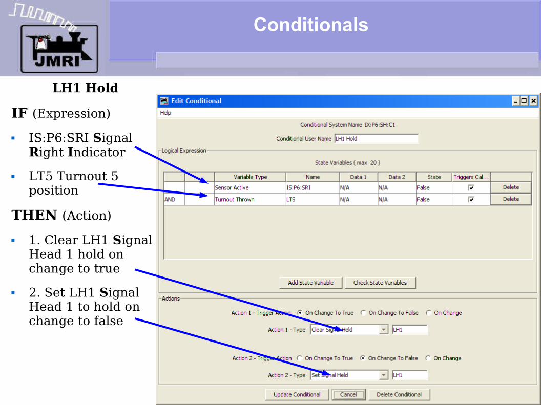
Conditionals
LH1 Hold
IF (Expression) IS:P6:SRI Signal
Right Indicator LT5 Turnout 5
position
THEN (Action) 1. Clear LH1 Signal
Head 1 hold on change to true
2. Set LH1 Signal Head 1 to hold on change to false

CTC Logix
What we have covered so far: CTC Panel operation detail (CTC-clinic-1) CTC Panel Logix (CTC-clinic-2)
Where we are going next: CTC Prototype Panel (CTC-clinic-3)