introduction to gm locomotives its systems
TRANSCRIPT

INTRODUCTION TO GM LOCOMOTIVES
&
ITS SYSTEMSBy
KAMALKANT
DyCEnHM/HQ/SCR
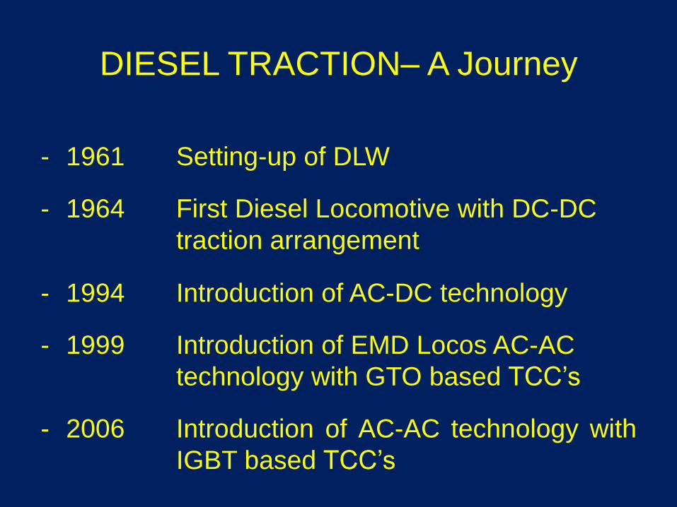
DIESEL TRACTION– A Journey
- 1961 Setting-up of DLW
- 1964 First Diesel Locomotive with DC-DC
traction arrangement
- 1994 Introduction of AC-DC technology
- 1999 Introduction of EMD Locos AC-AC
technology with GTO based TCC’s
- 2006 Introduction of AC-AC technology with
IGBT based TCC’s

GT46MAC
Single Cab
Turbocharged16 Cylinder
Full Width
CabA C
WDG4(GT46MAC) - A VARIANT OF SD70 EMD

1) Head light
2) Inertial Filter Air Inlet
3) Starting Fuse and Battery Knife Switch
4) Handrails
5) Cooling System Air Inlet
6) Radiator and Fan Access
7) Coupler “E” Type
8) Sanding Box (8)
9) Jacking Pads (4)
10) Wheels (6)
11) Fuel Tank
12) Compressed Air System Main Reservoirs
13) Battery Box
14) Trucks (3 axle 3 motor HTSC type) Qty. 2
15) Underframe
16) Dynamic Brake Grids
17) Dynamic Brake Fans (2)
GT46MAC - LAYOUT

14. Primary Fuel Filter
15. Air Compressor
16. Radiators
17. AC Radiator Cool. Fans (Qty. 2)
18. Draft Gear
19. Compressor Filter
20. Lube Oil Filter Tank
21. Lube Oil Strainer
22. Lube Oil Sump
23. Main Generator Assembly
24. No.1 Elect. Cntrl. Cab’t Air Filt.
25. Traction Motors (Qty. 6)
1. #1 Electrical Control Cabinet
2. Fuel Pump
3. Engine Starting Motors (Qty. 2)
4. Traction Control Cabinet
5. Traction Motor Cooling Blower
6. Main Gen. Assembly Blower
7. Engine Exhaust Stack
8. Engine Exhaust Manifold
9. Diesel Engine
10. Governor
11. Engine room Vent
12. Engine Water Tank
13. Lube Oil Cooler
GT46MAC - LAYOUT

• Two stroke turbo charged diesel engine.
• AC-AC Traction systems with AC generation & AC
traction motor.
• Locomotive consists of four microprocessors.
1. One loco control computer MAS 696/EM2000
2. Two Traction computers ASG
3. One Air brake computer CCB
• Sturdy, Bolsterless HTSC bogie with Huck fastening
arrangement.
MAIN FEATURES

MAIN FEATURES(Contd..)
• High Tractive Effort due to state of the art Creep Control
• Maximum tractive effort of 53 tonnes.
• Highly effective Dynamic Braking System available up to
near stand still.
• Maximum dynamic braking effort of 27 Tonnes.
• The despatchable adhesion of 43%.
• Longer trips – 90 days
• Very low engine idle RPM 200.

BENEFITS OF GM LOCO
• Lower Maintenance means smaller
shed infrastructure
• Fewer locos mean fewer running staff
• Higher HP and tractive effort mean
longer and faster trains
• Longer trips mean greater operational
flexibility

SALIENT FEATURES
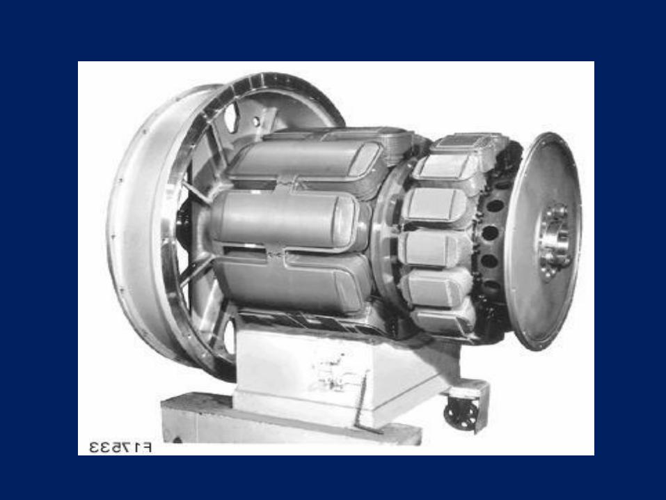
710 G3B ENGINE
710 cu in
displacement
Turbo Model G Railroad Application
16 cylinders

THE ENGINE-710G3B
16 Cylinder two stroke 45
degrees V Engine.
Compression ration 1:16.
Swept volume 710 cubic inches.
Engine control through
Woodward Governor.
Equipped with mechanical unit
injectors.
Unit replacement facility for
power assemblies.
No valve seat inserts.


Unit
exchange
type
Power
assembly

PISTON AND CON-ROD
Cast Steel Pistons
Simple Design
Splash Lubrication

CYLINDER LINER
Cast Iron
Laser Hardened
Water Jacketed
Side Ports for 2-stroke Design

FUEL OIL SYSTEM
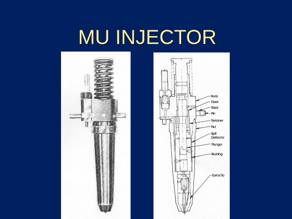
MU INJECTOR


Water Cooling System

Diesel EngineTraction
Alternator
Traction
Motors
Wheels
Aux M/csAC Gen
AC Motors
Rectifier
AC – AC traction
WDP4,WDG4
Inverter
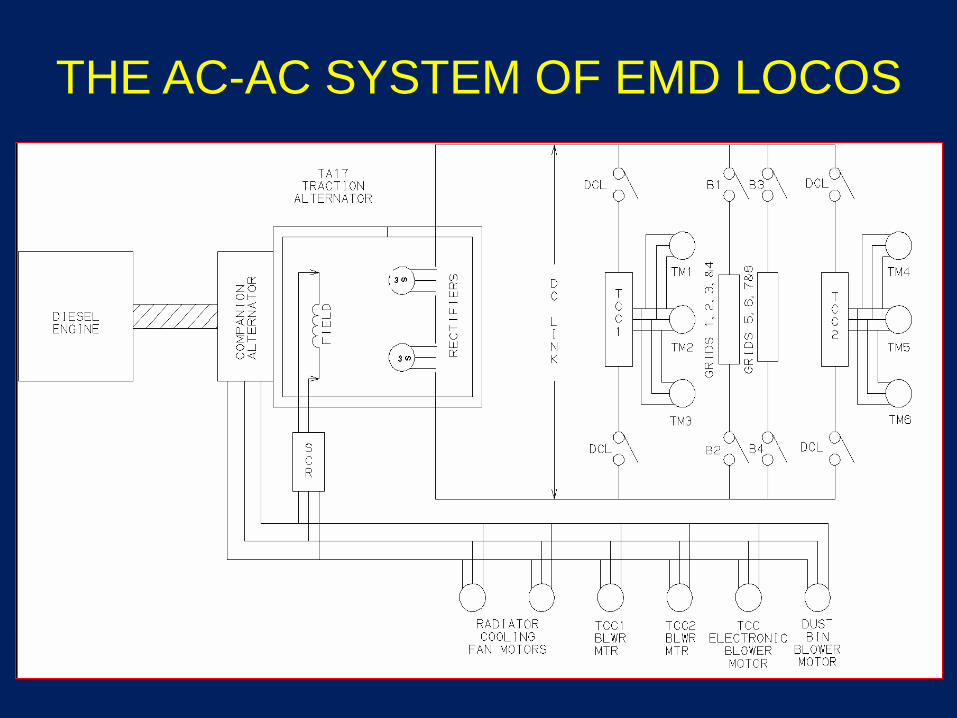
THE AC-AC SYSTEM OF EMD LOCOS

TRACTION ALTERNATOR
Out put voltage ranges from 600 to 2600 Volts.
Consists of two independent stator windings and a rotating field common to both the windings.
AC output rectified to DC by rectifier banks and permanently connected in series.
The output of traction alternator is used only for traction power.
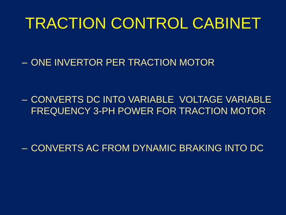
TRACTION CONTROL CABINET
– ONE INVERTOR PER TRACTION MOTOR
– CONVERTS DC INTO VARIABLE VOLTAGE VARIABLE
FREQUENCY 3-PH POWER FOR TRACTION MOTOR
– CONVERTS AC FROM DYNAMIC BRAKING INTO DC

TCC COMPUTER
• This computer controls the actions of traction control converter.
• It interacts with the main locomotive control computer,i.e., LCC through RS 485 serial link.
• The control of traction power is established through thiscomputer in coordination with LCC. It also monitorsvarious other parameters like temperature of variouscomponents, voltages, current, status of relays etc.,
• The computer performs all these functions through a setof 28 electronic modules. Each electronic moduleperforms different functions & monitor differentparameters.

TRACTION CONTROL COMPUTER

GATE UNITS & PHASE MODULES
The units actually involved in the process of inverting DC into AC

AC Traction Motor
vs
DC Traction Motor
Size is considerably
smaller
Much simpler
Coupled with suitable
control system gives
superior traction
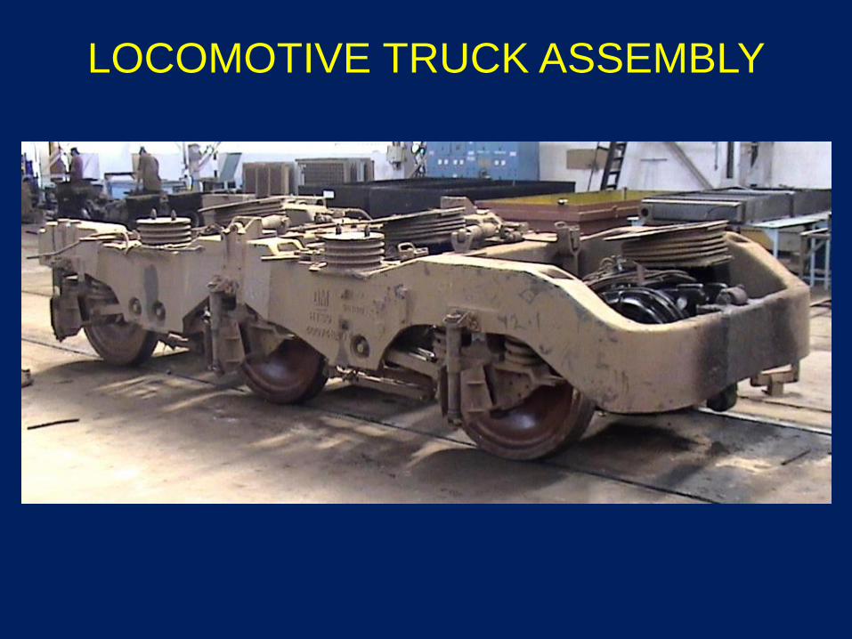
LOCOMOTIVE TRUCK ASSEMBLY

LOCOMOTIVE TRUCK ASSEMBLY
• Uniform traction motor orientation and stiff secondary
suspension improves weight transfer within the bogie for
optimal adhesion.
• Primary suspension with coil springs for good ride
quality.
• Secondary rubber springs (pads) also permit yaw on
curves
• Provision of yaw dampers & vertical shock absorbers forbetter ride quality and stability at higher road speeds.
• Reduced no. of wear rubbing surfaces for extendedmaintenance intervals.
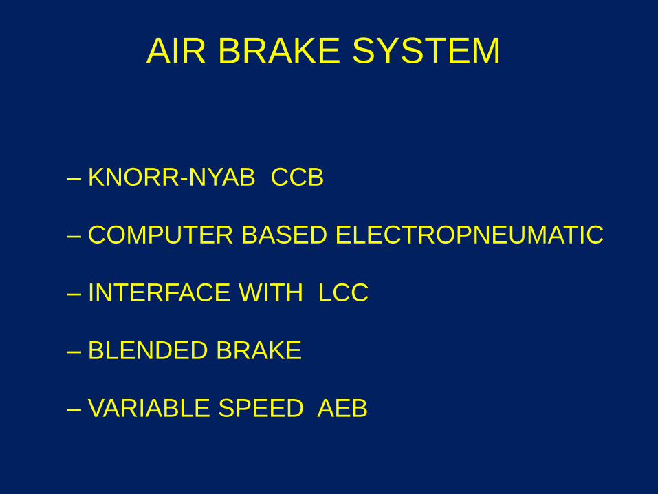
AIR BRAKE SYSTEM
– KNORR-NYAB CCB
– COMPUTER BASED ELECTROPNEUMATIC
– INTERFACE WITH LCC
– BLENDED BRAKE
– VARIABLE SPEED AEB
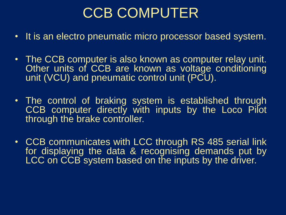
CCB COMPUTER
• It is an electro pneumatic micro processor based system.
• The CCB computer is also known as computer relay unit.Other units of CCB are known as voltage conditioningunit (VCU) and pneumatic control unit (PCU).
• The control of braking system is established throughCCB computer directly with inputs by the Loco Pilotthrough the brake controller.
• CCB communicates with LCC through RS 485 serial linkfor displaying the data & recognising demands put byLCC on CCB system based on the inputs by the driver.

CCB

RADAR ASSEMBLYLooks down at the ground
and compares the linear
speed of the loco with the
Rotary speed of the wheels
Controlled creep of wheels
on rail maximizes adhesion
and makes it possible to
utilise maximum torque of
traction motor for traction
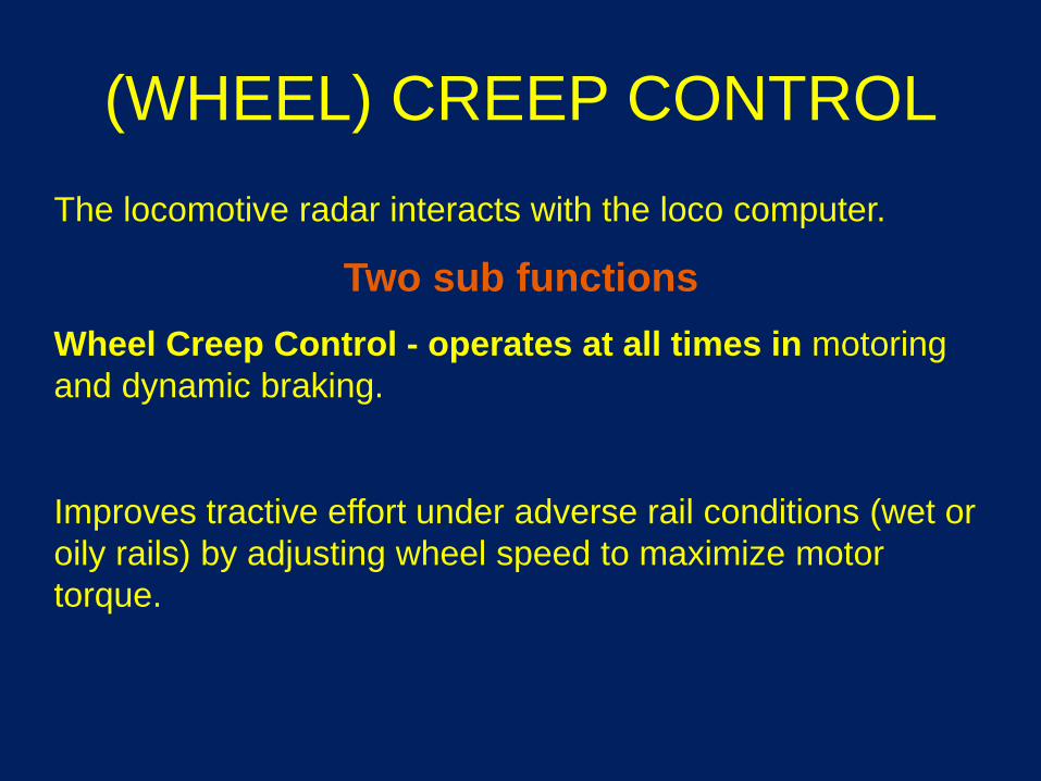
(WHEEL) CREEP CONTROL
The locomotive radar interacts with the loco computer.
Two sub functions
Wheel Creep Control - operates at all times in motoring
and dynamic braking.
Improves tractive effort under adverse rail conditions (wet or
oily rails) by adjusting wheel speed to maximize motor
torque.

Conventional
schWDG4 WDG3A
Trip 90 Days 15/30/40 Days
Quarterly 1 year M4, 8, 16,20
Half Yearly 3 Years M12
Yearly 6 Years M24, 48,72
POH 18 years 8 years
SCHEDULE PERIODICITY WDG4 & WDG3A
Authority: MP MISC 285 for WDG4
: MP MISC 140 &141 for WDG3A

COMPARISON OF WDG3A , WDG4 & WAG9
Description WDG3A WDG4 WAG9
Length (Mtrs.) 19.13 21.24 20.6
Weight in Tons 123 126 123
Brake System Pneumatic Micro processor Pneumatic/
micro processor
HP 3100 4500 6000
Starting Tractive
effort(KN)
398 520 460
Continuous TE(KN) 313 400 325
Slip control Wheel Slip relay
control
Computerised Relay control/
Computerised
Starting capability in
1/200 gradient(in tons)
4400 5190 4700

COMPARE WITH OTHER LOCOS
STARTING LOAD ON 1/150 GRADIENT
CLASS LOAD
BOXN TONNES
WDM 2 33 2700
WDG 2 47 3850
WAG 5 38 3110
WAG 7 46 3767
WAG9 52 4258
WDG4 58 4750

THANK YOU