introduction to fuel cells · 2020-03-03 · figure 1.5 basic comparison of batteries to fuel...
TRANSCRIPT

c01 JWPR067-Mench December 19, 2007 19:37 Char Count=
1
Introduction to Fuel Cells
The Stone Age didn’t end because they ran out of stones—but asa result of competition from the bronze tools, which better metpeople’s needs. I feel there’s something in the air—people areready to say that this is something we should do.
—Jeroen van der Veer, Chairman of Royal Dutch/Shell Group2000
1.1 PRELIMINARY REMARKS
The science and technology of fuel cell engines are both fascinating and continually evolv-ing. This point is emphasized by Figure 1.1, which shows the registered fuel-cell-relatedpatents in the United States, Canada, and the United Kingdom from 1975 through 2003.A similar acceleration of the patents granted in Japan and South Korea is also well un-derway, led by automotive manufacturers. The rapid acceleration in fuel cell develop-ment is not likely to wane in the near future, as the desire for decreased dependence onpetroleum supplies, lower pollution, and potential for high efficiency are driving this trendtoward an alternative power generation technology. Any attempt to bring the reader thestate-of-the art of the applied technology of fuel cell engines in a texbook would be hope-lessly antiquated by the time it was published. The designs, materials, and components offuel cell systems are constantly being improved for increased efficiency, durability, andlower cost.
At the heart of the ever-changing fuel cell technology, however, is an equally fascinatingand rich multidisciplinary fundamental science drawn from various engineering disciplines.The fundamentals of fuel cell science, emphasized in this textbook, are shown schematicallyin Figure 1.2. It is obvious that fuel cell science is not solely the domain of the electrochemistand can encompass nearly all engineering disciplines. Electrochemistry, thermodynamics,reaction kinetics, heat and mass transfer, fluid mechanics, and material science all playintegral roles in basic fuel cell design. Outside the basic science of an individual fuel cell liesystem and component issues that include manufacturing, sensing and control, vibration,and a plethora of other technologies. The goal of this text is to provide a fundamentalbackground on fuel cell science shown in Figure 1.2 to serve as an introduction to thiscaptivating and rapidly expanding field.
As discussed in Section 1.6, there have been several waves of concentrated fuel cellresearch and development, each driven by a somewhat different impetus. Throughout the
1
COPYRIG
HTED M
ATERIAL

c01 JWPR067-Mench December 19, 2007 19:37 Char Count=
2 Introduction to Fuel Cells
United States
600
400
200
0
800
1000
1200
United KingdomCanada
1975 1980 1985 1990 1995
Year of issue
Nu
mb
er o
f pat
ents
issu
ed
2000 2005
Figure 1.1 Timeline of worldwide patents in fuel cells for select countries based on data from U.S.,U.K., and Canadian patent offices.
history of development, however, the fundamental advantages common to all fuel cellsystems have included the following:
1. A potential for a relatively high operating efficiency, scalable to all size powerplants.
2. If hydrogen is used as fuel, pollution emissions are strictly a result of the productionprocess of the hydrogen.
Electrochemistry
Materials Thermodynamics
Fluid mechanics Reaction kinetics
Heat/mass transfer
Specific FC phenomena
FC system components
Figure 1.2 Major engineering disciplines involved in fundamental fuel cell science.

c01 JWPR067-Mench December 19, 2007 19:37 Char Count=
1.2 Fuel Cells as Electrochemical Engines 3
3. No moving parts, with the significant exception of pumps, compressors, and blowersto drive fuel and oxidizer.
4. Multiple choices of potential fuel feedstocks, from existing petroleum, natural gas,or coal reserves to renewable ethanol or biomass hydrogen production.
5. A nearly instantaneous recharge capability compared to batteries.
It should be noted that fuel cells must not be seen as a panacea for every power-generating application need in the world. There are many specific applications, however,where fuel cell use has great potential to have a major impact on future power generation.Before this conversion can occur, however, the following technical limitations common toall fuel cell systems must be overcome:
1. Alternative materials and construction methods must be developed to reduce fuel cellsystem cost to be competitive with the automotive combustion engine (∼$30/kW)and stationary power generation systems (∼$1000/kW). The cost of the catalyst nolonger dominates the price of most fuel cell systems, although it is still significant.Manufacturing and mass production technology are now also key components tothe commercial viability of fuel cell systems.
2. Suitable reliability and durability must be achieved. The performance of every fuelcell gradually degrades with time due to a variety of phenomena. The automotivefuel cell must withstand load cycling and freeze–thaw environmental swings with anacceptable level of degradation from the beginning-of-lifetime (BOL) performanceover a lifetime of 5500 h (equivalent to 165,000 miles at 30 mph). A stationaryfuel cell must withstand over 40,000 h of steady operation under vastly changingexternal temperature conditions.
3. Suitable system power density and specific power must be achieved. The U.S.Department of Energy year 2010 targets for system power density and specificpower are 650 W/kg and 650 W/L for automotive (50-kW) applications, 150 W/kgand 170 W/L for auxiliary (5–10-kW peak) applications, and 100 W/kg and100 W/L for portable (milliwatt to 50-W) power systems [1].
4. Fuel storage, generation, and delivery technology must be advanced if pure hydrogenis to be used. Hydrogen storage and generation are discussed in Chapter 8. Thehydrogen infrastructure and delivery are also addressed in ref. [2].
5. Desired performance and longevity of system ancillary components must beachieved. New hardware (e.g., efficient transformers and high-volume blowers)must be developed to suit the needs of fuel cell power systems.
6. Sensors and online control systems for fuel cell systems are needed, especially fortransient operation, where performance instability can become a major issue.
The advantages and disadvantages of particular fuel cell systems are discussed ingreater detail throughout this book.
1.2 FUEL CELLS AS ELECTROCHEMICAL ENGINES
Fuel Cells versus Heat Engines The first question many people ask is “why are thesesystems called fuel cell engines?” An engine is a device that converts energy into useful
c01 JWPR067-Mench December 19, 2007 19:37 Char Count=
4 Introduction to Fuel Cells
Same initial chemical energy
Heat engine
Electrochemical engine
Thermal energy
Waste heat
Power
Waste heat
Power
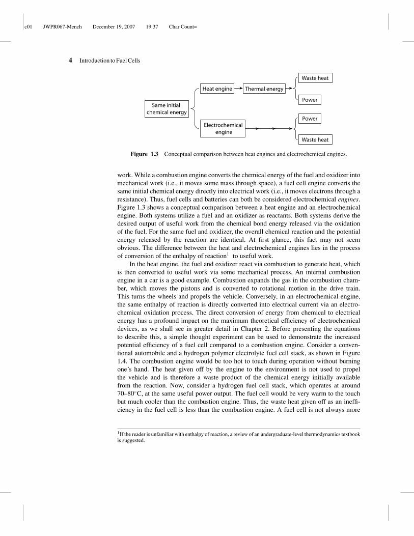
Figure 1.3 Conceptual comparison between heat engines and electrochemical engines.
work. While a combustion engine converts the chemical energy of the fuel and oxidizer intomechanical work (i.e., it moves some mass through space), a fuel cell engine converts thesame initial chemical energy directly into electrical work (i.e., it moves electrons through aresistance). Thus, fuel cells and batteries can both be considered electrochemical engines.Figure 1.3 shows a conceptual comparison between a heat engine and an electrochemicalengine. Both systems utilize a fuel and an oxidizer as reactants. Both systems derive thedesired output of useful work from the chemical bond energy released via the oxidationof the fuel. For the same fuel and oxidizer, the overall chemical reaction and the potentialenergy released by the reaction are identical. At first glance, this fact may not seemobvious. The difference between the heat and electrochemical engines lies in the processof conversion of the enthalpy of reaction1 to useful work.
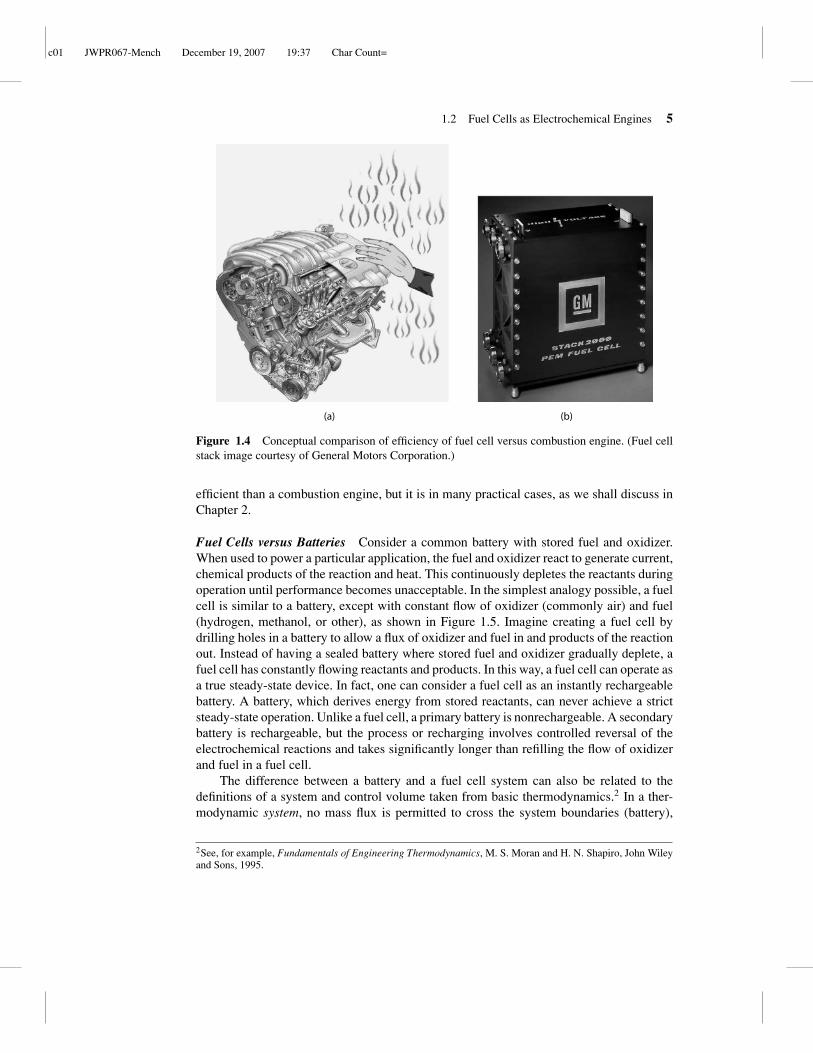
In the heat engine, the fuel and oxidizer react via combustion to generate heat, whichis then converted to useful work via some mechanical process. An internal combustionengine in a car is a good example. Combustion expands the gas in the combustion cham-ber, which moves the pistons and is converted to rotational motion in the drive train.This turns the wheels and propels the vehicle. Conversely, in an electrochemical engine,the same enthalpy of reaction is directly converted into electrical current via an electro-chemical oxidation process. The direct conversion of energy from chemical to electricalenergy has a profound impact on the maximum theoretical efficiency of electrochemicaldevices, as we shall see in greater detail in Chapter 2. Before presenting the equationsto describe this, a simple thought experiment can be used to demonstrate the increasedpotential efficiency of a fuel cell compared to a combustion engine. Consider a conven-tional automobile and a hydrogen polymer electrolyte fuel cell stack, as shown in Figure1.4. The combustion engine would be too hot to touch during operation without burningone’s hand. The heat given off by the engine to the environment is not used to propelthe vehicle and is therefore a waste product of the chemical energy initially availablefrom the reaction. Now, consider a hydrogen fuel cell stack, which operates at around70–80◦C, at the same useful power output. The fuel cell would be very warm to the touchbut much cooler than the combustion engine. Thus, the waste heat given off as an ineffi-ciency in the fuel cell is less than the combustion engine. A fuel cell is not always more
1If the reader is unfamiliar with enthalpy of reaction, a review of an undergraduate-level thermodynamics textbookis suggested.
c01 JWPR067-Mench December 19, 2007 19:37 Char Count=
1.2 Fuel Cells as Electrochemical Engines 5
(a) (b)
Figure 1.4 Conceptual comparison of efficiency of fuel cell versus combustion engine. (Fuel cellstack image courtesy of General Motors Corporation.)
efficient than a combustion engine, but it is in many practical cases, as we shall discuss inChapter 2.
Fuel Cells versus Batteries Consider a common battery with stored fuel and oxidizer.When used to power a particular application, the fuel and oxidizer react to generate current,chemical products of the reaction and heat. This continuously depletes the reactants duringoperation until performance becomes unacceptable. In the simplest analogy possible, a fuelcell is similar to a battery, except with constant flow of oxidizer (commonly air) and fuel(hydrogen, methanol, or other), as shown in Figure 1.5. Imagine creating a fuel cell bydrilling holes in a battery to allow a flux of oxidizer and fuel in and products of the reactionout. Instead of having a sealed battery where stored fuel and oxidizer gradually deplete, afuel cell has constantly flowing reactants and products. In this way, a fuel cell can operate asa true steady-state device. In fact, one can consider a fuel cell as an instantly rechargeablebattery. A battery, which derives energy from stored reactants, can never achieve a strictsteady-state operation. Unlike a fuel cell, a primary battery is nonrechargeable. A secondarybattery is rechargeable, but the process or recharging involves controlled reversal of theelectrochemical reactions and takes significantly longer than refilling the flow of oxidizerand fuel in a fuel cell.
The difference between a battery and a fuel cell system can also be related to thedefinitions of a system and control volume taken from basic thermodynamics.2 In a ther-modynamic system, no mass flux is permitted to cross the system boundaries (battery),
2See, for example, Fundamentals of Engineering Thermodynamics, M. S. Moran and H. N. Shapiro, John Wileyand Sons, 1995.

c01 JWPR067-Mench December 19, 2007 19:37 Char Count=
6 Introduction to Fuel Cells
Depletingfuel andoxidizer
Battery
e
(a)
-
Fuel cell
(b)
Fuel in
Depletedfuel and products out
Oxidizer in
Depletedoxidizer and products out
Anode Cathode
Figure 1.5 Basic comparison of batteries to fuel cells: (a) battery; (b) fuel cell.
while in a thermodynamic control volume, mass flux is permitted across the boundaries(fuel cell).
1.3 GENERIC FUEL CELL AND STACK
Basic Operating Principles Figure 1.6 shows a schematic of a generic fuel cell withcomponents common to most fuel cell types shown. Referring to Figure 1.6, separateliquid- or gas-phase fuel and oxidizer streams enter through flow channels, separated by theelectrolyte/electrode assembly. Reactants are transported by diffusion and/or convectionto the catalyst layer (electrode), where electrochemical reactions take place to generatecurrent. Some fuel cells have a porous (typical porosity ∼0.6–0.8) contact layer betweenthe electrode and current collecting reactant flow channels that functions to transportelectrons and species to and from the electrode surface. In polymer electrolyte fuel cells

c01 JWPR067-Mench December 19, 2007 19:37 Char Count=
1.3 Generic Fuel Cell and Stack 7
Figure 1.6 Schematic of a generic fuel cell.
(PEFCs) discussed in Chapter 6, an electrically conductive carbon paper or cloth diffusionmedium (DM) layer (also called gas diffusion layer, or GDL) serves this purpose, and aDM covers the anode and cathode catalyst layer.
At the anode electrode, the electrochemical oxidation of the fuel produces electrons thatflow through the bipolar plate (also called cell interconnect) to the external circuit, whilethe ions generated migrate through the electrolyte to complete the circuit. The electronsin the external circuit drive the load (e.g., electric moter or other device) and return to thecathode catalyst where they recombine with the oxidizer in the cathodic oxidizer reductionreaction (ORR). The products of the fuel cell are thus threefold: (1) chemical products, (2)waste heat, and (3) electrical power.
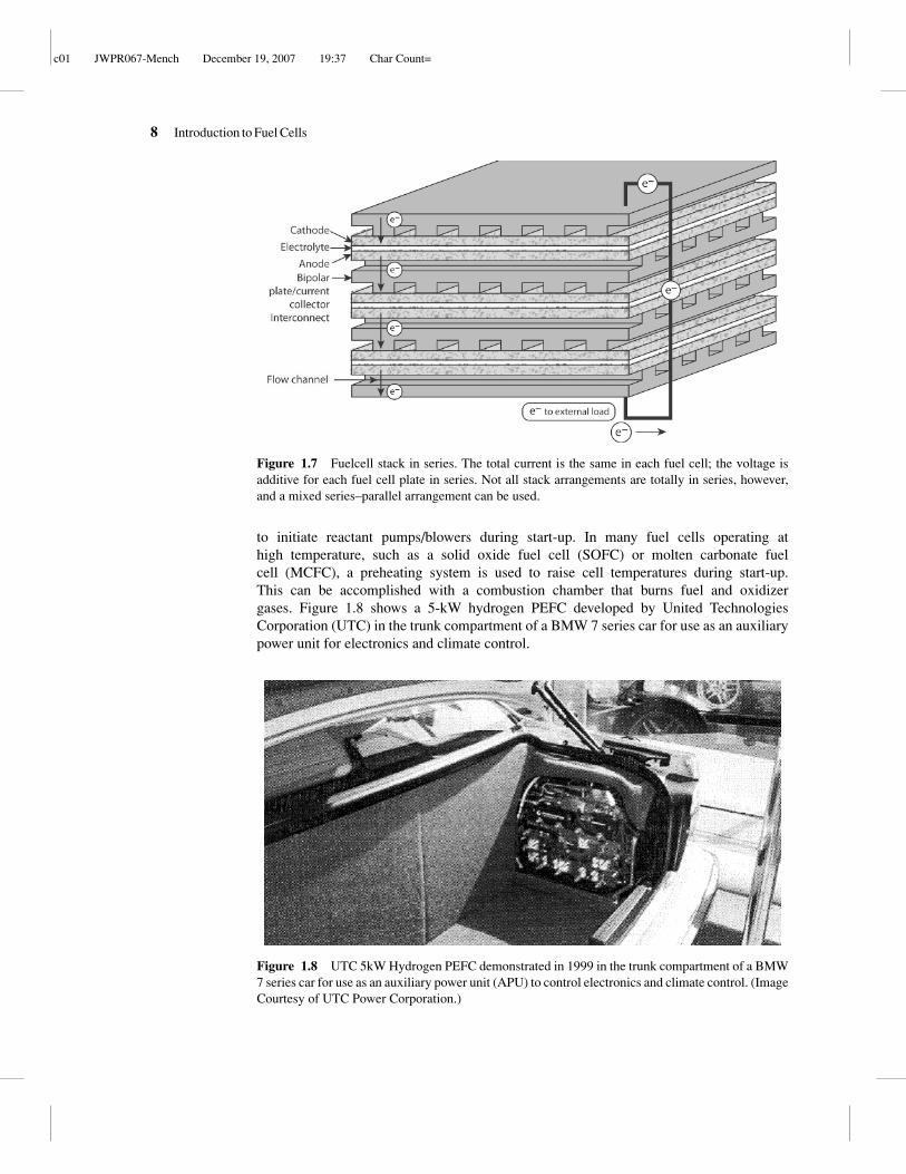
Description of a Fuel Cell Stack A single fuel cell can theoretically achieve whatevercurrent and power are required simply by increasing the size of the active electrode areaand reactant flow rates. However, the output voltage of a single fuel cell is limited bythe fundamental electrochemical potential of the reacting species involved and is alwaysless than 1 V for realistic operating conditions. Therefore, to achieve a higher voltage andcompact design, a fuel cell stack of several individual cells connected in series is utilized.Series-parallel combinations are also utilized in some systems as well. Figure 1.7 is aschematic of a generic planar fuel cell stack assembly without a flow manifold and showsthe flow of current through the system. For a stack in series, the total current is proportionalto the active electrode area of each cell in the stack and is the same through all cells inseries. The total stack voltage is simply the sum of the individual cell voltages. For fuel cellsin parallel, the current is additive and the voltage is the same in each cell. For applicationsthat benefit from higher voltage output, such as automotive stacks, over 200 fuel cells in asingle stack can be used.
Other components necessary for fuel cell system operation include subsystemsfor fuel and oxidizer delivery, voltage regulation and electronic control, fuel and pos-sibly oxidizer storage, fuel recirculation/consumption, stack temperature control, andsystem sensing of control parameters. For the PEFC, separate humidification systemsare also needed to ensure optimal performance and stability. A battery is often used
c01 JWPR067-Mench December 19, 2007 19:37 Char Count=
8 Introduction to Fuel Cells
Figure 1.7 Fuelcell stack in series. The total current is the same in each fuel cell; the voltage isadditive for each fuel cell plate in series. Not all stack arrangements are totally in series, however,and a mixed series–parallel arrangement can be used.
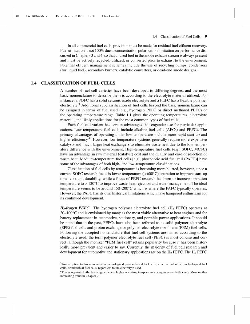
to initiate reactant pumps/blowers during start-up. In many fuel cells operating athigh temperature, such as a solid oxide fuel cell (SOFC) or molten carbonate fuelcell (MCFC), a preheating system is used to raise cell temperatures during start-up.This can be accomplished with a combustion chamber that burns fuel and oxidizergases. Figure 1.8 shows a 5-kW hydrogen PEFC developed by United TechnologiesCorporation (UTC) in the trunk compartment of a BMW 7 series car for use as an auxiliarypower unit for electronics and climate control.
Figure 1.8 UTC 5kW Hydrogen PEFC demonstrated in 1999 in the trunk compartment of a BMW7 series car for use as an auxiliary power unit (APU) to control electronics and climate control. (ImageCourtesy of UTC Power Corporation.)
c01 JWPR067-Mench December 19, 2007 19:37 Char Count=
1.4 Classification of Fuel Cells 9
In all commercial fuel cells, provision must be made for residual fuel effluent recovery.Fuel utilization is not 100% due to concentration polarization limitation on performance dis-cussed in Chapters 3 and 4, so that unused fuel in the anode exhaust stream is always presentand must be actively recycled, utilized, or converted prior to exhaust to the environment.Potential effluent management schemes include the use of recycling pumps, condensers(for liquid fuel), secondary burners, catalytic converters, or dead-end anode designs.
1.4 CLASSIFICATION OF FUEL CELLS
A number of fuel cell varieties have been developed to differing degrees, and the mostbasic nomenclature to describe them is according to the electrolyte material utilized. Forinstance, a SOFC has a solid ceramic oxide electrolyte and a PEFC has a flexible polymerelectrolyte.3 Additional subclassification of fuel cells beyond the basic nomenclature canbe assigned in terms of fuel used (e.g., hydrogen PEFC or direct methanol PEFC) orthe operating temperature range. Table 1.1 gives the operating temperatures, electrolytematerial, and likely applications for the most common types of fuel cells.
Each fuel cell variant has certain advantages that engender use for particular appli-cations. Low-temperature fuel cells include alkaline fuel cells (AFCs) and PEFCs. Theprimary advantages of operating under low temperature include more rapid start-up andhigher efficiency.4 However, low-temperature systems generally require more expensivecatalysts and much larger heat exchangers to eliminate waste heat due to the low temper-ature difference with the environment. High-temperature fuel cells (e.g., SOFC, MCFC)have an advantage in raw material (catalyst) cost and the quality and ease of rejection ofwaste heat. Medium-temperature fuel cells [e.g., phosphoric acid fuel cell (PAFC)] havesome of the advantages of both high- and low-temperature classifications.
Classification of fuel cells by temperature is becoming more blurred, however, since acurrent SOFC research focus is lower temperature (<600◦C) operation to improve start-uptime, cost and durability, while a focus of PEFC research has been to increase operationtemperature to >120◦C to improve waste heat rejection and water management. The idealtemperature seems to be around 150–200◦C which is where the PAFC typically operates.However, the PAFC has its own historical limitations which have hampered enthusiasm forits continued development.
Hydrogen PEFC The hydrogen polymer electrolyte fuel cell (H2 PEFC) operates at20–100◦C and is envisioned by many as the most viable alternative to heat engines and forbattery replacement in automotive, stationary, and portable power applications. It shouldbe noted that in the past, PEFCs have also been referred to as solid polymer electrolyte(SPE) fuel cells and proton exchange or polymer electrolyte membrane (PEM) fuel cells.Following the accepted nomenclature that fuel cell systems are named according to theelectrolyte used, the term polymer electrolyte fuel cell (PEFC) is most concise and cor-rect, although the moniker “PEM fuel cell” retains popularity because it has been histor-ically more prevalent and easier to say. Currently, the majority of fuel cell research anddevelopment for automotive and stationary applications are on the H2 PEFC. The H2 PEFC
3An exception to this nomenclature is biological process based fuel cells, which are identified as biological fuelcells, or microbial fuel cells, regardless to the electrolyte used.4This is opposite to the heat engine, where higher operating temperatures bring increased efficiency. More on thisinteresting trend in Chapter 2.

c01 JWPR067-Mench December 19, 2007 19:37 Char Count=
Tabl
e1.
1Fu
elC
ellT
ypes
,Des
crip
tions
,and
Bas
icD
ata
Fuel
Cel
lTy
peE
lect
roly
teM
ater
ial
Ope
ratin
gTe
mpe
ratu
re(◦ C
)M
ajor
Pois
onA
dvan
tage
sD
isad
vant
ages
Mos
tPro
mis
ing
App
licat
ions
Alk
alin
efu
elce
llSo
lutio
nof
pota
ssiu
mhy
drox
ide
inw
ater
60–2
50a
CO
2H
igh
effic
ienc
y,lo
wox
ygen
read
uctio
nre
actio
nlo
sses
Mus
trun
onpu
reox
ygen
with
outC
O2
cont
amin
ant
Spac
eap
plic
atio
nsw
ithpu
reO
2/H
2
avai
labl
e
Phos
phor
icac
idfu
elce
ll
Solu
tion
ofph
osph
oric
acid
inpo
rous
silic
onca
rbid
em
atri
x
160–
220
Sulf
ur,h
igh
leve
lsof
CO
1–2%
CO
tole
rant
,go
od-q
ualit
yw
aste
heat
,de
mon
stra
ted
dura
bilit
y
Low
pow
erde
nsity
,ex
pens
ive,
plat
inum
cata
lyst
used
,slo
wst
art-
up,l
oss
ofel
ectr
olyt
e
Prem
ium
stat
iona
rypo
wer
Solid
oxid
efu
elce
llY
ttria
(Y2O
2)
stab
ilize
dzi
rcon
ia(Z
rO2)
600–
1000
Sulf
urC
Oto
lera
nt,f
uelfl
exib
le,
high
-qua
lity
was
tehe
at,
inex
pens
ive
cata
lyst
Lon
gst
art-
uptim
e,du
rabi
lity
unde
rth
erm
alcy
clin
g,in
activ
ityof
elec
trol
yte
belo
w∼6
00◦ C
Stat
iona
rypo
wer
with
coge
nera
tion,
cont
inuo
us-p
ower
appl
icat
ions
Mol
ten
carb
onat
efu
elce
ll
Mol
ten
alka
lim
etal
(Li/K
orL
i/Na)
carb
onat
esin
poro
usm
atri
x
600–
800
Sulf
urC
Oto
lera
nt,f
uelfl
exib
le,
high
-qua
lity
was
tehe
at,
inex
pens
ive
cata
lyst
Ele
ctro
lyte
diss
olve
sca
thod
eca
taly
st,
extr
emel
ylo
ngst
art-
uptim
e,ca
rbon
diox
ide
mus
tbe
inje
cted
toca
thod
e,el
ectr
olyt
em
aint
enan
ce
Stat
iona
rypo
wer
with
coge
nera
tion,
cont
inuo
us-p
ower
appl
icat
ions
Poly
mer
elec
trol
yte
fuel
cellb
Flex
ible
solid
per-
fluor
osul
foni
cac
idpo
lym
er
30–1
00C
O,S
ulfu
r,m
etal
ions
,per
oxid
eL
ow-t
empe
ratu
reop
erat
ion,
high
effic
ienc
y,hi
ghH
2
pow
erde
nsity
,rel
ativ
ely
rapi
dst
art-
up
Exp
ensi
veca
taly
st,
dura
bilit
yof
com
pone
nts
noty
etsu
ffici
ent,
poor
-qua
lity
was
tehe
at,
Into
lera
nce
toC
O,
ther
mal
and
wat
erm
anan
gem
ent
Port
able
,au
tom
otiv
e,an
dst
atio
nary
appl
icat
ions
aM
oder
nA
FCs<
100◦
C.
bIn
clud
esdi
rect
met
hano
lfue
lcel
land
dire
ctal
coho
lfue
lcel
ls.
10

c01 JWPR067-Mench December 19, 2007 19:37 Char Count=
1.4 Classification of Fuel Cells 11
Figure 1.9 UTC Power supplies fuel cell bus powerplants for transit programs in the United Statesand Europe. The fuel economy of transit buses powered by a UTC Power PureMotionTM fuel cellsystem is two times better than a diesel-powered bus. Fuel cell-powered buses also emit no harmfultailpipe emissions and operate quietly. (Image Courtesy of UTC Power Corporation.)
is fueled either by pure hydrogen or from a diluted hydrogen mixture generated from afuel reformation process. A stack power density of greater than 1.3 kW/L is typical. Sincethe operating temperature is from room temperature to ∼80◦C, a noble metal platinumcatalyst is typically used on the anode and cathode. Figure 1.9 is a picture of a PEFC enginedeveloped by UTC Power for city bus applications. The H2 PEFC has many technical issuesthat complicate performance and control. Besides issues of manufacturing, ancillary systemcomponents, cost, and market acceptance, the main remaining technical challenges for thefuel cell itself include (1) water and heat management, (2) durability, and (3) freeze–thawcycling and frozen-start capability.
Direct Methanol Fuel Cell The liquid-fed direct methanol fuel cell (DMFC) is generallyseen as the most viable alternative to lithium ion batteries in portable applications becauseDMFC systems require less ancillary equipment and can therefore potentially be moresimplified compared to an H2 PEFC. Additionally, the usc of a liquid fuel simplifiesstorage. The DMFCs can potentially compete favorably with advanced Li ion batteries(which currently power many wireless portable applications) in terms of gravimetric energydensity of ∼120–160 Wh/kg and volumetric energy density of ∼230–270 Wh/L. While bothH2 PEFCs and DMFCs are strictly PEFCs (both use the same flexible polymer electrolyte),the DMFC feeds a liquid solution of methanol and water to the anode as fuel. The additionalcomplexities of the low-temperature methanol oxidation reaction prevent the DMFC from

c01 JWPR067-Mench December 19, 2007 19:37 Char Count=
12 Introduction to Fuel Cells
(a)
(b)
Figure 1.10 Photograph of (a) PDA/smart phone concept model and (b) a handheld entertainmentsystem concept model. Both are powered by Mobionő fuel cell technology, which uses a directmethanol fuel cell for power. (Image Courtesy of Mechanical Technology, Inc. (MTI).)
c01 JWPR067-Mench December 19, 2007 19:37 Char Count=
1.4 Classification of Fuel Cells 13
obtaining the same level of fuel cell power density as the H2 PEFC. Figure 1.10 is a pictureof a portable DMFC developed by MTI Micro for hand-held power application.
Four main technical issues affecting performance remain: (1) two-phase flow man-agement in the anode and cathode, (2) methanol crossover, (3) poor catalyst activity, and(4) high catalyst loading. While significant progress has been made by various groupsto develop optimized catalysts, total noble metal catalyst loading is still on the order of10 mg/cm2. Typically a platinum–ruthenium catalyst is utilized on the anode for methanoloxidation, and a platinum catalyst is utilized on the cathode as in the H2 PEFC [3]. TheDMFC is discussed in greater detail in Chapter 6.
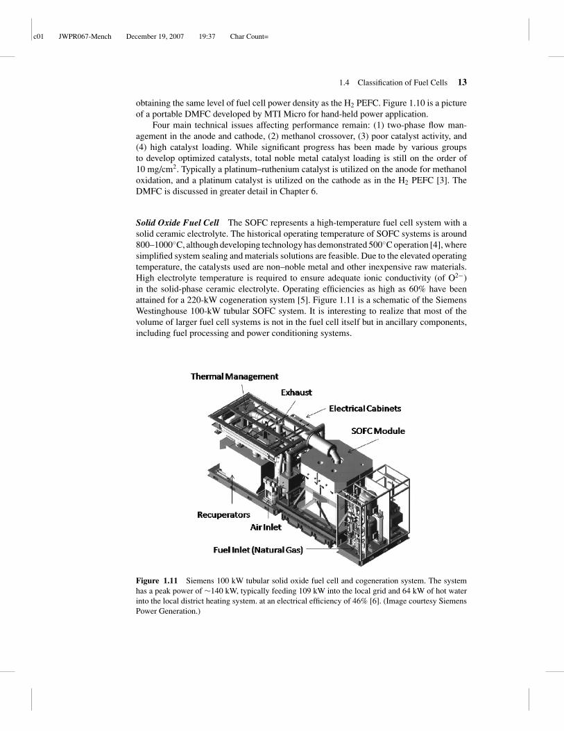
Solid Oxide Fuel Cell The SOFC represents a high-temperature fuel cell system with asolid ceramic electrolyte. The historical operating temperature of SOFC systems is around800–1000◦C, although developing technology has demonstrated 500◦C operation [4], wheresimplified system sealing and materials solutions are feasible. Due to the elevated operatingtemperature, the catalysts used are non–noble metal and other inexpensive raw materials.High electrolyte temperature is required to ensure adequate ionic conductivity (of O2−)in the solid-phase ceramic electrolyte. Operating efficiencies as high as 60% have beenattained for a 220-kW cogeneration system [5]. Figure 1.11 is a schematic of the SiemensWestinghouse 100-kW tubular SOFC system. It is interesting to realize that most of thevolume of larger fuel cell systems is not in the fuel cell itself but in ancillary components,including fuel processing and power conditioning systems.
Figure 1.11 Siemens 100 kW tubular solid oxide fuel cell and cogeneration system. The systemhas a peak power of ∼140 kW, typically feeding 109 kW into the local grid and 64 kW of hot waterinto the local district heating system. at an electrical efficiency of 46% [6]. (Image courtesy SiemensPower Generation.)
c01 JWPR067-Mench December 19, 2007 19:37 Char Count=
14 Introduction to Fuel Cells
There has been much recent development in the United States on SOFC systems,incubated by the Department of Energy Solid State Energy Conversion Alliance (SECA)program. The 10-year goal of the SECA program (started in the fall of 1999) is to develop3–10-kw SOFC units at <$400/kW with rated performance achievable over the lifetime ofthe application with less than 0.1% loss per 500 h operation by 2021 [7].
Besides manufacturing and economic issues, the main technical limitations of theSOFC include achieving a reduced operating temperature, controling start-up time, dura-bility, and proper cell-sealing. The SOFC is discussed in depth in Chapter 7.
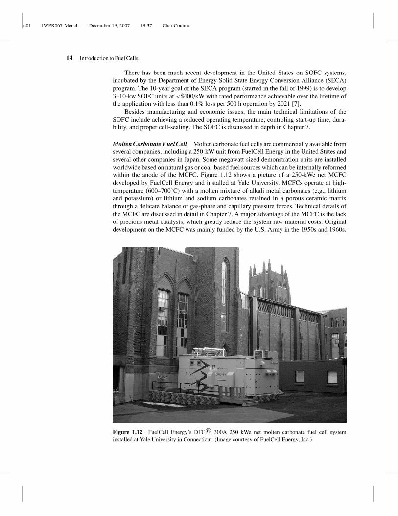
Molten Carbonate Fuel Cell Molten carbonate fuel cells are commercially available fromseveral companies, including a 250-kW unit from FuelCell Energy in the United States andseveral other companies in Japan. Some megawatt-sized demonstration units are installedworldwide based on natural gas or coal-based fuel sources which can be internally reformedwithin the anode of the MCFC. Figure 1.12 shows a picture of a 250-kWe net MCFCdeveloped by FuelCell Energy and installed at Yale University. MCFCs operate at high-temperature (600–700◦C) with a molten mixture of alkali metal carbonates (e.g., lithiumand potassium) or lithium and sodium carbonates retained in a porous ceramic matrixthrough a delicate balance of gas-phase and capillary pressure forces. Technical details ofthe MCFC are discussed in detail in Chapter 7. A major advantage of the MCFC is the lackof precious metal catalysts, which greatly reduce the system raw material costs. Originaldevelopment on the MCFC was mainly funded by the U.S. Army in the 1950s and 1960s.
Figure 1.12 FuelCell Energy’s DFCő 300A 250 kWe net molten carbonate fuel cell systeminstalled at Yale University in Connecticut. (Image courtesy of FuelCell Energy, Inc.)

c01 JWPR067-Mench December 19, 2007 19:37 Char Count=
1.4 Classification of Fuel Cells 15
The U.S. Army desired operation of power sources from logistic fuel already available,thus requiring high temperatures with internal fuel reformation that can be provided bythe MCFC. During this period, significant advances of this liquid electrolyte alternativeto the SOFC were made [8]. Development waned somewhat after this early development,but advances have continued and MCFC commercialization has been achieved. The maindisadvantages of MCFCs include (1) complex electrolyte management and loss throughfinite vapor pressure, (2) extremely long start-up time (the MCFC is generally suitable onlyfor continuous power operation), (3) durability, and (4) carbon dioxide injection into theanode is needed to maintain electrolyte stability.
Phosphoric Acid Fuel Cell The PAFC was originally developed for commercial appli-cation in the 1960s. The PAFC has an acidic, mobile (liquid) electrolyte of high con-centration phosphoric acid contained by a porous silicon carbide ceramic matrix andoperates at around 160–220◦C. A 200-kW PAFC array that powers the Verizon callrouting center in New York is shown in Figure 1.13. Like the MCFC, the electrolyteis bound by capillary and gas pressure forces between porous electrode structures. ThePAFC is in many ways similar to the PEFC, except the acid-based electrolyte is in liq-uid form and the operating temperature is slightly higher. Over two-hundred 200-kWcommercial PAFC units were developed and sold by United Technologies Corporationthrough several different divisions and subsidiaries, and many are still in operation.
Figure 1.13 The Verizon call routing center in Garden City, New York, is home to the largest U.S.commercial fuel cell installation of its kind. The fuel cells from UTC Power generate 200 kilowattseach, providing a total of 1.4 megawatts of clean power to the center. (Image Courtesy of UTC PowerCorporation.)

c01 JWPR067-Mench December 19, 2007 19:37 Char Count=
16 Introduction to Fuel Cells
However, ubiquitous commercial application has not been achieved, primarily due to thehigh cost of approximately $4500/kW, about five times greater than cost targets for conven-tional stationary applications [9]. The main advantages of the PAFC include (1) the highoperating temperature allows operation with 1–2% CO in fuel stream, (2) the highly con-centrated acid electrolyte does not need water for conductivity, making water managementvery simple compared to the PEFC, and (3) the demonstrated long life and commercialsuccess for premium stationary power of the PAFC. Besides the high system cost, the maintechnical disadvantages of the PAFC include (1) a bulky, heavy system compared to PEFCwith area-specific power less than half of the PEFC (0.2–0.3 W/cm2 [10], (2) continued useof platinum catalyst with nearly the same loading as PEFCs, (3) the relatively long warm-uptime until the electrolyte is conductive at ∼160◦C (although warm-up time is much lessthan the MCFC or SOFC), and (4) the liquid electrolyte has finite vapor pressure, resultingin continual loss of electrolyte in the vapor phase. Modern PAFC design includes coolingand condensation zones to mitigate this loss. The PAFC is discussed in greater detail inChapter 7.
Alkaline Fuel Cell Alkaline fuel cells utilize a solution of potassium hydroxide in wa-ter as an alkaline, mobile (liquid) electrolyte. Alkaline fuel cells were originally devel-oped as an auxillary power unit APU for space applications by the Soviet Union and theUnited States in the 1950s and served on the Apollo program as well as the Space Shut-tle orbiter. A 12-kW AFC used to provide power and potable water for astronauts in theSpace Shuttle orbiter is shown in Figure 1.14. The AFCs were chosen for space applica-tions for their high efficiency and robust operation. The AFC operates around 60–250◦Cwith greatly varied design and operating conditions. Modern designs tend to operate atthe lower range of temperature and pressure near ambient conditions. The primary ad-vantages of the AFC are the lower cost of materials and electrolyte and high operatingefficiency (60% demonstrated for space applications) due to use of an alkaline electrolyte.
Figure 1.14 12-kW fuel cell power plant for the Space Shuttle Orbiter. Three units power theorbiter while in space as well as provide the drinking water for the astronauts. (Image Courtesy ofUTC Power Corporation.)
c01 JWPR067-Mench December 19, 2007 19:37 Char Count=
1.5 Potential Fuel Cell Applications and Markets 17
For alkaline electrolytes, the oxidizer reduction reaction (ORR) kinetics are more effi-cient than acid-based electrolytes (e.g., PEFC, PAFC). Many space applications utilizepure oxygen and hydrogen for chemical propulsion, so the AFC was well suited as anAPU. However, the alkaline electrolyte suffers an intolerance to even small fractions ofcarbon dioxide (CO2) found in air which react to form potassium carbonate (K2CO3) inthe electrolyte, gravely reducing performance over time. For terrestrial applications, CO2
poisoning has limited lifetime of AFC systems to well below that required for commercialapplication, and filtration of CO2 has proven too expensive for practical use. Due to thislimitation, relatively little commercial development of the AFC beyond space applicationshas been realized. Some recent development of alkaline-based solid polymer electrolytesis underway, however. The AFC is discussed in greater detail in Chapter 7.
Other Fuel Cells Many other fuel cell systems exist, and new versions are constantlybeing developed. Many of these are simply existing fuel cell systems with a different fuel.For example, PEFCs based on a direct alcohol solution offer alternatives to DMFCs forportable power and include those based on formic acid [11], dimethyl ether [12], ethyleneglycol, dimethyl oxalate, and other so-called direct alcohol fuel cells (DAFCs) [13, 14].
A completely different concept is the biologically based fuel cell. Biologically basedfuel cells use biocatalysts for conversion of chemical to electrical energy and can beclassified into two basic categories: (1) microbial fuel cells (MFCs) and (2) enzyme-based fuel cells. In the MFC, electricity is generated by anerobic oxidation of organicmaterial by bacteria. The catalytic activity and transport of protons are accomplished usingbiological enzymes or exogenous mediators [15–17]. Although performance is relativelyquite low, on the order of 0.1–1 mA/cm2, the potential for generating some power, orsimply power-neutral decomposition and treatment of domestic waste matter, currently amultibillion-dollar cost to society, is potentially quite significant.
The enzyme-based biological fuel cell has significantly greater power density(1–10 mA/cm2) than the microbial fuel cell, although power produced is still orders ofmagnitude lower than a conventional precious metal catalyzed H2 PEFC [17]. However,enzymatic fuel cells have distinct advantages in terms of potential cost and operation atambient temperature in near-neutral-pH environments. Enzymatic fuel cells are envisionedas implantable power devices in humans or as using environmentally derived fuel from treesaps for long-term remote sensor applications [18]. While biologically based fuel cells areprobably the least-developed fuel cell power source, the unique aspects of the catalytic pro-cess and potential for natural sugar-based power are intriging. Another potentially interest-ing application on which this author has pondered is a weight loss fuel cell where blood sugarwould be used to power an external fuel cell device, effectively burning calories with nophysical exercise required. The feasibility of this concept is further explored in Problem 22.
1.5 POTENTIAL FUEL CELL APPLICATIONSAND MARKETS
Fuel cells have the potential to replace existing power sources for many applications. Figures1.15 and 1.16 show the exponential progression of commercial stationary power fuel cellinstallations and hydrogen refueling stations worldwide. Although the trends look promis-ing, they currently represent only an infinitesimal fraction of the fueling infrastructure
c01 JWPR067-Mench December 19, 2007 19:37 Char Count=
18 Introduction to Fuel Cells
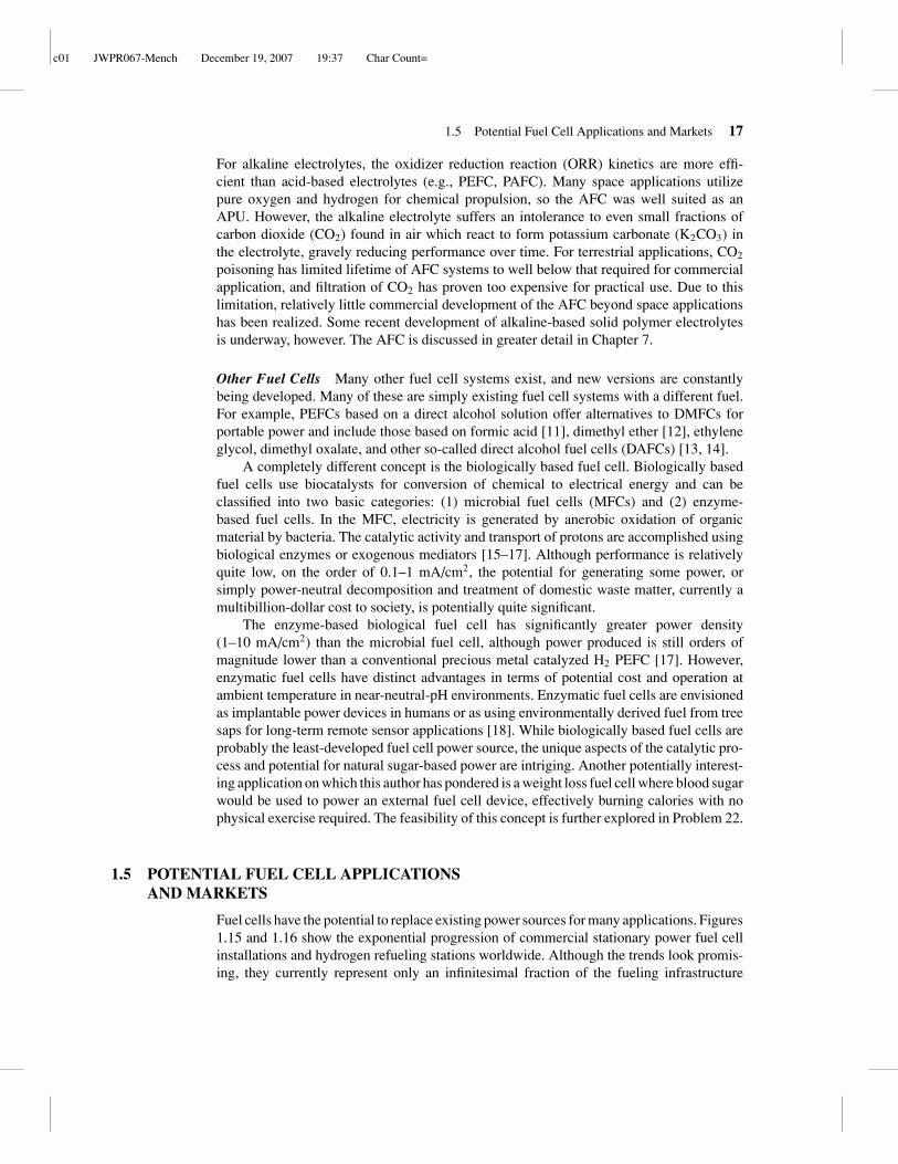
Figure 1.15 Commercial large (>10-kW) stationary power fuel cell installations under operationversus year. (Data adapted from Ref. [19].)
required for practical widespread use. Fuel generation, storage, and delivery infrastructureare still major barriers that must be overcome. Hydrogen generation, storage, and deliveryare discussed in Chapter 8. Hydrogen infrastructure is a vast and speculative subject, andvarious summaries can be found [20, 21]. The most likely consumer applications for fuelcells include portable (0–100-W), stationary (0–25-kW), and transportation (∼100-kW)applications. Each market has unique demands that tend to be more suited to a particulartype of fuel cell. For portable applications, high system power density and simplicity are de-sired over efficiency and cost. For stationary applications, durability and high efficiency arehigher priorities. For transportation applications, compact size, rapid start-up, robustness,and high efficiency are the primary technical goals.
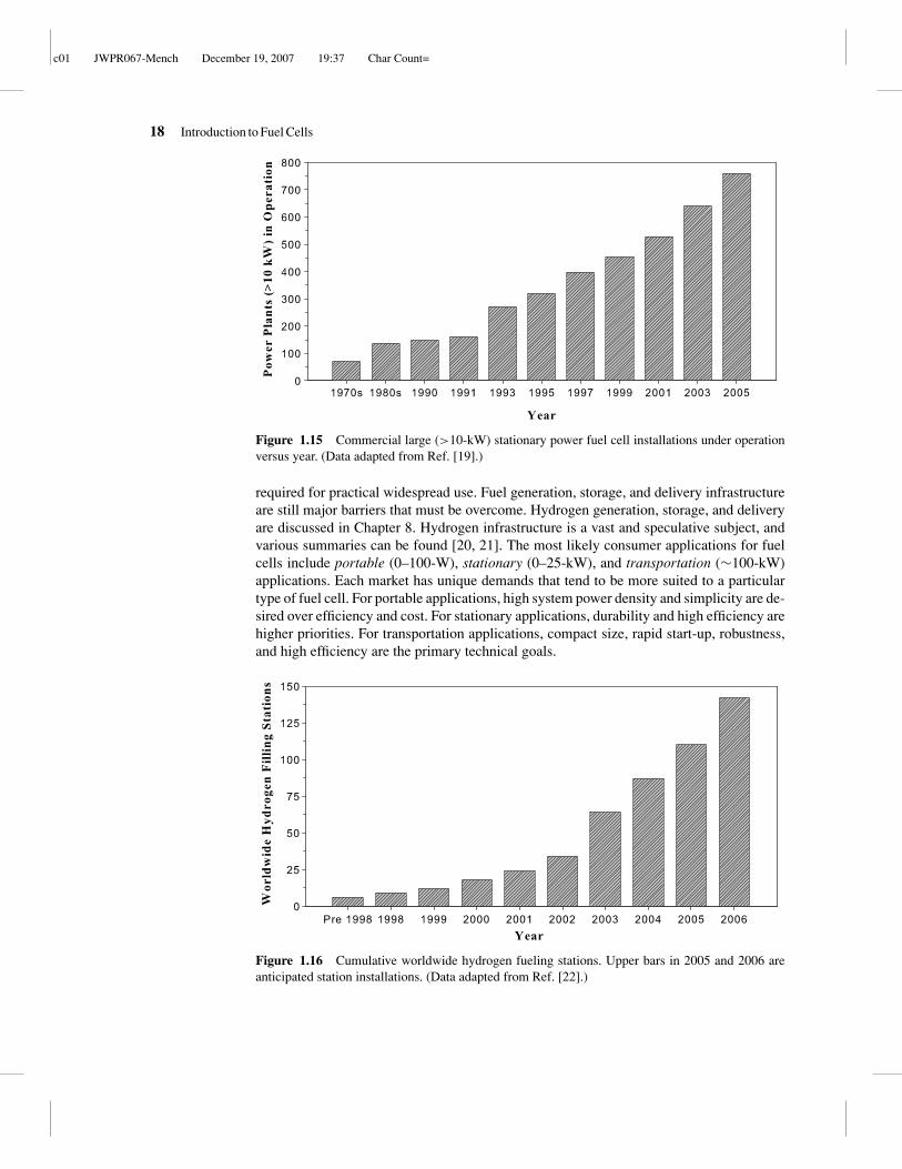
Figure 1.16 Cumulative worldwide hydrogen fueling stations. Upper bars in 2005 and 2006 areanticipated station installations. (Data adapted from Ref. [22].)

c01 JWPR067-Mench December 19, 2007 19:37 Char Count=
1.5 Potential Fuel Cell Applications and Markets 19
Figure 1.17 Toshiba 100 mWe micro direct methanol fuel cell which weighing 8.5 g (0.3 oz) [23].(Image Courtesy Toshiba Corporation.)
Portable Applications Perhaps where fuel cells show the most promise for ubiquitousnear-term implementation is in portable power (0–100-W) applications, such as cell phonesand laptop computers. Current battery technology has not yet provided the energy density re-quired for long-term operation, and recharging is time consuming. Additionally, the cost ofexisting premium power battery systems is already on the same order as contemporary fuelcells, with additional development anticipated. With replaceable fuel cartridges, portablefuel cell systems have the additional advantage of instant and remote rechargeability that cannever be matched with secondary battery systems. A hand-held DMFC for portable powerdeveloped by Toshiba is planned for production. The 8.5-g DMFC shown in Figure 1.17is rated at 100 mW continuous power (up to 20 h) and measures 22 mm × 56 mm × 4.5mm, including a maximum of 9.1 mm for the concentrated methanol fuel tank [24]. As thewireless economy progresses, demand for higher power, smaller, and instantly recharge-able technologies will undoubtedly continue to push forward development of portablefuel cells.
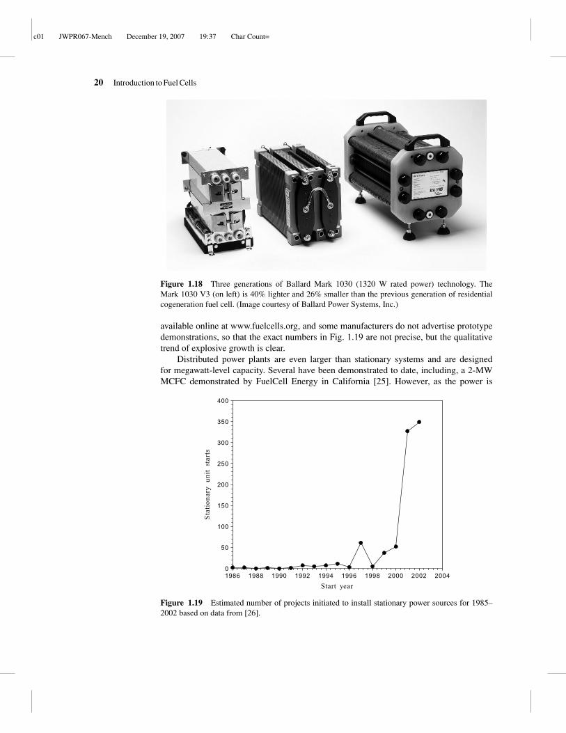
Stationary and Distributed Power Applications Stationary (1–500-kW) applications in-clude power units for homes or auxiliary and backup power generation units. Stationaryapplications are designed for nearly continuous use and therefore must have far greaterlifetime than automotive units, although operation at a near-continuous steady state isadvantageous for durability. Stationary devices typically range from 1 kW temporary orauxiliary power generator units, examples of which are the Ballard fuel cell generator unitsshown in Figure 1.18, to 100-kW systems for regular power of buildings. Unlike the portablefuel cell, where ancillary components are reduced as much as possible, the stationary fuelcell system is not similarly constrained, and typically has an array of components to achievehigh-efficiency, durable operation.
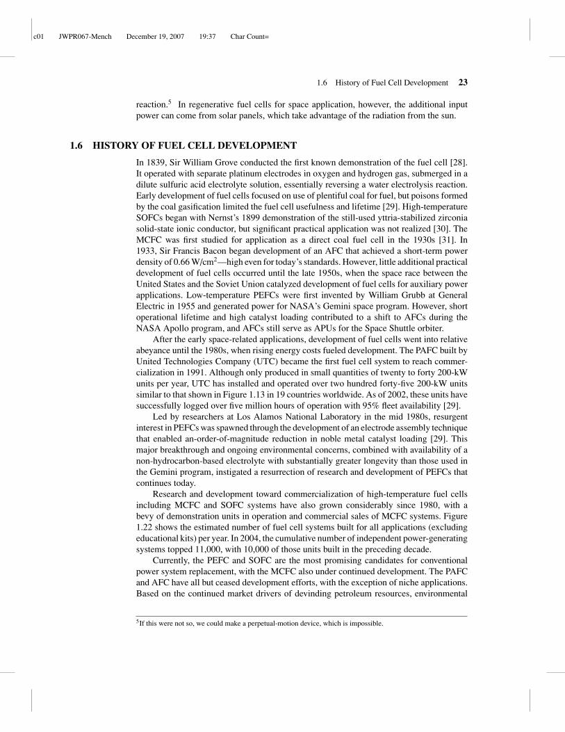
A plot showing the estimated number of demonstration and commercial units in thestationary power category from 1985 to 2002 is given in Figure 1.19. Not surprisingly,the exponential growth in the number of online units follows a similar qualitative trendto the available patents granted for various fuel cell technologies shown in Figure 1.1.The early rise in stationary units in 1997 was primarily a result of PAFC systems soldby United Technologies Corporation, although recently most additional units have beenPEFCs from various manufacturers. Data are estimated from the best available compilation
c01 JWPR067-Mench December 19, 2007 19:37 Char Count=
20 Introduction to Fuel Cells
Figure 1.18 Three generations of Ballard Mark 1030 (1320 W rated power) technology. TheMark 1030 V3 (on left) is 40% lighter and 26% smaller than the previous generation of residentialcogeneration fuel cell. (Image courtesy of Ballard Power Systems, Inc.)
available online at www.fuelcells.org, and some manufacturers do not advertise prototypedemonstrations, so that the exact numbers in Fig. 1.19 are not precise, but the qualitativetrend of explosive growth is clear.
Distributed power plants are even larger than stationary systems and are designedfor megawatt-level capacity. Several have been demonstrated to date, including, a 2-MWMCFC demonstrated by FuelCell Energy in California [25]. However, as the power is
y
us
Figure 1.19 Estimated number of projects initiated to install stationary power sources for 1985–2002 based on data from [26].

c01 JWPR067-Mench December 19, 2007 19:37 Char Count=
1.5 Potential Fuel Cell Applications and Markets 21
scaled up to megawatt levels, the efficiency advantages of fuel cells become less favorablecompared to gas turbine based cogeneration units, which has limited development of fuelcells for megawatt distributed applications.
Transportation Applications Perhaps the most exciting potential application for fuel cellpower is in transportation. The potential for high efficiency with low pollution, and severingthe umbilical cord between the oil industry and the world economy is a strong driver towarddevelopment of fuel cell vehicles. Even early fuel cell pioneers also dreamed of fuel cellvehicles, and some early prototypes were built, such as the alkaline fuel cell built byKordesh shown in Figure 1.20. The bottles on the roof of the car are actually laboratorycylinders of hydrogen, an approach that is obviously not recommended for safety but wasnevertheless successful. Hundreds of fuel-cell-powered prototype vehicles are now in thetesting stage. In 2003, Toyota leased around 20 fuel cell Rav-4 vehicles for ∼ US$10,000per month. Figure 1.21 shows a prototype fuel cell vehicle built by Hyundai and Kia MotorCompany.
Although the potential benefits to society are tremendous, fuel cells for transportationapplications suffer the most daunting technological hurdles. The existing combustion enginetechnology market dominance will be difficult to usurp, considering its low comparativecost (∼$30/kW), high durability, high power density, suitability for rapid cold start, andhigh existing degree of optimization. Additionally, the success of high-efficiency hybridelectric/combustion engine technology adds another rapidly evolving target fuel cells mustmatch. The lack of an existing hydrogen fuel infrastructure and other issues make it highlylikely that initial introduction would be in the form of fleet vehicles such as buses, taxicabs, or postal vehicles. In this case, a single refueling station would be needed, and drivingcycles and maintenance could be controlled and measured. In fact, many such demonstration
Figure 1.20 Early 5-kW alkaline fuel cell car built and driven on public roads by K. Kordesch[27]. Tanks on the top are for hydrogen storage. (Reproduced with permission from Ref. [27].)

c01 JWPR067-Mench December 19, 2007 19:37 Char Count=
22 Introduction to Fuel Cells
Figure 1.21 UTC Power develops proton exchange membrane fuel cell technology for next gen-eration automobiles and works with major automobile manufacturers, including Hyundai. (Imagecourtesy of UTC Power Corporation.)
projects exist. Fuel cell buses have been in operation in cities such as Vancouver, Canada,and Chicago, Illinois, for several years.
Other Niche Applications Any application requiring electrical power could potentiallyoperate on fuel cells, although not all make practical sense. The military has a need for fuelcells for battery replacement and transportation applications. The heavy weight and cost ofprimary batteries make fuel cells attractive, even just for training purposes. Replacing someof the nonrechargeable batteries presently used with reusable fuel cells would representa major reduction in waste. Additionally, the potential for stealth and long life wirelessoperation is attractive for military reconnaissance and remote-sensing applications. Formilitary transportation, higher efficiency and longer ranges would be a great benefit, assome estimates put the cost of a gallon of fuel delivered to the battlefield at over $100.
Regenerative fuel cells are especially suited for space applications, where cargo cancost up to $10,000 per pound to take to space. In a regenerative fuel cell powered by hydro-gen and oxygen, the closed fuel cell vessel actually operates as a battery, producing currentfrom stored oxygen and hydrogen when in the power mode. In the power mode, productwater is generated from the electrochemical reactions. In the regeneration mode, the wateris electrolyzed back into oxygen and hydrogen by reversal of the hydrogen oxidation andoxidizer reduction reactions. Through this cycle, the fuel and oxidizer are continually recy-cled and reused, reducing the weight of reactants required to be put into orbit for a chosenduty cycle. Of course, the second law of thermodynamics requires more electrical poweris input into the electrolysis than is produced by power generating hydrogen oxidation
c01 JWPR067-Mench December 19, 2007 19:37 Char Count=
1.6 History of Fuel Cell Development 23
reaction.5 In regenerative fuel cells for space application, however, the additional inputpower can come from solar panels, which take advantage of the radiation from the sun.
1.6 HISTORY OF FUEL CELL DEVELOPMENT
In 1839, Sir William Grove conducted the first known demonstration of the fuel cell [28].It operated with separate platinum electrodes in oxygen and hydrogen gas, submerged in adilute sulfuric acid electrolyte solution, essentially reversing a water electrolysis reaction.Early development of fuel cells focused on use of plentiful coal for fuel, but poisons formedby the coal gasification limited the fuel cell usefulness and lifetime [29]. High-temperatureSOFCs began with Nernst’s 1899 demonstration of the still-used yttria-stabilized zirconiasolid-state ionic conductor, but significant practical application was not realized [30]. TheMCFC was first studied for application as a direct coal fuel cell in the 1930s [31]. In1933, Sir Francis Bacon began development of an AFC that achieved a short-term powerdensity of 0.66 W/cm2—high even for today’s standards. However, little additional practicaldevelopment of fuel cells occurred until the late 1950s, when the space race between theUnited States and the Soviet Union catalyzed development of fuel cells for auxiliary powerapplications. Low-temperature PEFCs were first invented by William Grubb at GeneralElectric in 1955 and generated power for NASA’s Gemini space program. However, shortoperational lifetime and high catalyst loading contributed to a shift to AFCs during theNASA Apollo program, and AFCs still serve as APUs for the Space Shuttle orbiter.
After the early space-related applications, development of fuel cells went into relativeabeyance until the 1980s, when rising energy costs fueled development. The PAFC built byUnited Technologies Company (UTC) became the first fuel cell system to reach commer-cialization in 1991. Although only produced in small quantities of twenty to forty 200-kWunits per year, UTC has installed and operated over two hundred forty-five 200-kW unitssimilar to that shown in Figure 1.13 in 19 countries worldwide. As of 2002, these units havesuccessfully logged over five million hours of operation with 95% fleet availability [29].
Led by researchers at Los Alamos National Laboratory in the mid 1980s, resurgentinterest in PEFCs was spawned through the development of an electrode assembly techniquethat enabled an-order-of-magnitude reduction in noble metal catalyst loading [29]. Thismajor breakthrough and ongoing environmental concerns, combined with availability of anon-hydrocarbon-based electrolyte with substantially greater longevity than those used inthe Gemini program, instigated a resurrection of research and development of PEFCs thatcontinues today.
Research and development toward commercialization of high-temperature fuel cellsincluding MCFC and SOFC systems have also grown considerably since 1980, with abevy of demonstration units in operation and commercial sales of MCFC systems. Figure1.22 shows the estimated number of fuel cell systems built for all applications (excludingeducational kits) per year. In 2004, the cumulative number of independent power-generatingsystems topped 11,000, with 10,000 of those units built in the preceding decade.
Currently, the PEFC and SOFC are the most promising candidates for conventionalpower system replacement, with the MCFC also under continued development. The PAFCand AFC have all but ceased development efforts, with the exception of niche applications.Based on the continued market drivers of devinding petroleum resources, environmental
5If this were not so, we could make a perpetual-motion device, which is impossible.

c01 JWPR067-Mench December 19, 2007 19:37 Char Count=
24 Introduction to Fuel Cells
Por
tabl
e F
uel C
ell S
yste
ms
Figure 1.22 Estimated cumulative number of portable fuel cell systems built (excluding educationalkits) by year. (Based on data adapted from Ref. [32].)
concerns, and wireless technology needs, it is evident that, despite the lingering technicalchallenges, continued development of a variety of fuel cell systems will evolve towardimplementation in many, but certainly not all, potential applications. In some cases, im-provement of existing or other alternative power sources or the exiting technical barrierswill ultimately doom ubiquitous application of fuel cells, while some applications are likelyto enjoy commercial success.
1.7 SUMMARY
The goal of this chapter was to introduce the reader to the wide variety of fuel cellengine technologies available and begin to dissect them in terms of operating parameters,strengths and limitations, and potential applications. The basic nomenclature of fuel cellswas introduced, along with the various methods for classification of the various systemsunder development. Fuel cell implementation in portable, stationary, and transportationapplications, is highly likely to occur during this century, although the pace is limited bysome technological, safety, and infrastructural hurdles. Some fuel cell systems, such as thePAFC and MCFC, have already made it to the commercialization stage, although not yet ona major scale. Other fuel cell systems were heavily developed in the past but developmenthas been nearly ceased due to certain technical or cost limitations. In the end, fuel cellsare not a panacea that will solve every power generation need, but they do have significantpotential advantages that engender their long-term implementation in many applications.
APPLICATION STUDY: SOCIOECONOMIC IMPACTOF FUEL CELL IMPLEMENTATION
Imagine that fuel cells are implemented on a worldwide basis in consumer automotivevehicles in the next 20 years. On the one hand, the possible elimination of petroleum

c01 JWPR067-Mench December 19, 2007 19:37 Char Count=
Problems 25
as a primary fuel source seems incredibly attractive: Middle Eastern instability and thegrowing Chinese and Indian economies threaten to increase oil prices and stifle world-wide economic growth and development. On the other hand, automotive fuel cells wouldrequire hydrogen, which is not a readily available resource and must be produced in anenergy-intensive process that is still many times more expensive per unit of energy thanpetroleum. Additionally, the most likely automotive power plant replacement is the PEFC,which requires platinum catalyst. Platinum is a precious metal and ironically less readilyavailable than the petroleum it replaces. The question posed is this: Are the worldwideplatinum resources readily available or not? That is, if fuel cells do replace a significantnumber of automotive combustion engines over the coming years, will the market for plat-inum be as precarious as the future market for petroleum? The answer to this question isquite complex and varies depending on the source of information. For this assignment, youmust investigate the available resources and make some engineering estimates to come toyour own conclusion. Answer the following question in a short written report and includethe websites and resources you consulted. Do you think replacing 50% of the cars on the roadwith fuel cells would affect world platinum markets? You will need to estimate theautomotive power plants required worldwide, the amount of platinum per fuel cell,the average power of the fuel cell used, and several other things. The point of this ex-ercise is to look beyond the text to find reliable Internet and other resources and useengineering logic to come to a reasonable scientific conclusion. It is likely that notevery person will come to the same conclusion, but your conclusion should be justi-fied with reasonable assumptions. Hint: You can use the numbers in Problem 18 to getstarted.
PROBLEMS
Calculation/Short Answer Problems
1.1 Go online and try to find 10 reliable fuel cell infor-mation websites. There are good general sites as well asindustrial sites with reliable information available. Thereare also dozens in not hundreds of sites with questionableaccuracy.
1.2 Go online and identify companies that currently are de-veloping each fuel cell technology listed in Table 1.1. Whichtechnologies have the most/least current developers?
1.3 Go online to the U.S. Patent and Trade Office and de-termine how many fuel-cell-related patents were grantedfor the latest year available. How does it compare toFigure 1.1?
1.4 Describe the differences between a battery and a fuelcell.
1.5 List the relative advantages and disadvantages of thePAFC, SOFC, MCFC, AFC, H2 PEFC, and DMFC. Listone potential power application well suited for each type offuel cell.
1.6 List some potential niche applications for fuel cells.
1.7 Why do you think AFCs have been successfully imple-mented in space applications?
1.8 Why don’t fuel cell manufacturers simply use one largefuel cell plate to obtain the required power output insteadof stacking many fuel cell plates?
1.9 Why would a stack be aligned in series or parallel andwhat specific advantages can you think of where a combi-nation of series and parallel would be useful?
1.10 Find a market price for hydrogen gas and normalizethe energy content compared to the current local price ofgasoline. Using octane as an approximation for gasolineenergy content, compare the cost per kilojoule of energy ofhydrogen to gasoline. What cost per liter of gasoline do youthink must be reached before the hydrogen fuel source iseconomically competitive?
1.11 Estimate the current approximate cost per kilowattof power from a standard automotive combustion engine.

c01 JWPR067-Mench December 19, 2007 19:37 Char Count=
26 Introduction to Fuel Cells
(Hint: You can find this information if you do an internetsearch of “crate engines.”) This is the cost target for fuelcell systems.
1.12 Estimate the current approximate cost per kilowattof power from a standard laptop computer and cell phonebattery. This is the cost target for portable cell systems.
1.13 Estimate the current approximate cost per kilowatt ofpower from a standard stationary power generator system.This is the cost target for stationary cell systems.
1.14 Estimate the power density of a combustion engineon a volume basis, that is, kilowatts per liter. Compare thisto a power density for PEFCs of 1.3 kW/L.
1.15 Make a plot of the volume of gas-phase hydrogenrequired to contain the equivalent energy in a gallon ofgasoline as a function of pressure of 0–10,000 psig. (Hint:Assume the ideal gas law is valid.)
1.16 List the three products of reaction from an operatingfuel cell and discuss how each can be utilized in a fuel cellsystem.
1.17 Consider an automotive application where nominally300 V is required to operate the electric motors poweringthe wheels. If the fuel cells operate at an average cell voltageof 0.6 V, 1.1 A/cm2, how many cells in series will the stackhave? If the cells are 300 cm2 active area each, what is thetotal current out of the stack? If the stack is now arrangedwith the individual cells in parallel, rather than in series,what is the current and voltage output of the stack? Is therea difference in power output (Pe = IV) of the two designs(parallel vs. series)? Why would we choose one design overthe other in a practical application?
Open-Ended Problems
1.18 Consider that, at present, about 0.8 mg/cm2 total ofplatinum is used to make a hydrogen fuel cell that canoperate at around 0.65 W/cm2. Calculate how much plat-inum would be needed to replace 50% of the cars on theroad in the United States alone with fuel cells. Do you
think this would affect world platinum markets? Note: Youwill have to go outside the textbook to answer this ques-tion as well as make some reasonable estimates to enablecalculation. Although it is clear that a great reduction inthe precious metal loading of a hydrogen fuel cell wouldbe desirable to achieve ubiquitous implementation, thereare differing views about the effect that such a conversionwould have. Do you think platinum recycling would beneccessary?
1.19 List some potential power source applications wherea fuel cell could potentially replace a battery and discussthe relative advantages and disadvantages of this. Use Ta-ble 1.1 to help you decide which fuel cell would be mostappropriate for each application.
1.20 List some potential power source applications wherea fuel cell could potentially replace a combustion-basedpower source and discuss the relative advantages anddisadvantages of this. Use Table 1.1 to help you de-cide which fuel cell would be most appropriate for eachapplication.
1.21 For a hydrogen-based economy, a large supply of hy-drogen will be needed. There are many ways in which hy-drogen generation can be achieved. Do some research anddiscuss the various potential sources of hydrogen and com-ment on the advantages and drawbacks of each source. Youcan start in Chapter 8 of this text, but there are many moreresources you can find.
1.22 Consider development of a fuel cell for weight loss.That is, a fuel cell would be attached to the human bodyand be fueled from the glucose in the bloodstream, effec-tively burning calories from the user’s blood effortlessly.Consider a current biological glucose-burning fuel cell cur-rent density of 5 mA/cm2 at 0.4 V and a fuel cell stackmounted next to the person with 100 cm2 per plate and 3mm total per plate. Calculate the approximate volume of aweight loss fuel cell stack to burn 500 food calories (e.g.,500,000 thermodynamic calories) in an hour of use. Is thispracticals? What current density would make this approachfeasible?
REFERENCES
1. U.S. Department of Energy 2003 Multi-Year Research, Development and Demonstration Planfor Fuel Cells, http://www.eere.energy.gov/hydrogenandfuelcells/mypp/pdfs/3.4 fuelcells.pdf.
2. D. Sperling, and J. S. Cannon, The Hydrogen Energy Transition: Moving Toward the PostPetroleum Age in Transportation, Academic, 2004.

c01 JWPR067-Mench December 19, 2007 19:37 Char Count=
References 27
3. J. Muller, G. Frank, K. Colbow, and D. Wilkinson, “Transport/Kinetic Limitations and Effi-ciency Losses,” in Handbook of Fuel Cells—Fundamentals, Technology and Applications, Vol. 4,W. Vielstich, A. Lamm, and H. A. Gasteiger, Eds., Wiley, 2003, pp. 847–855.
4. R. Doshi, V. L. Richards, J. D. Carter, X. Wang, and M. Krumpelt, “Development of Solid-OxideFuel Cells that Operate at 500◦C,” J. Electrochem. Soc., Vol. 146, No. 4, pp. 1273–1278, 1999.
5. R. F. Service, “New Tigers in the Fuel Cell Tank,” Science, Vol. 288, pp. 1955–1957, 2000.
6. http://www.siemenswestinghouse.com/en/fuelcells/hybrids/index.cfm.
7. U.S. Department of Energy SECA Program, http://www.netl.doe.gov/seca/, 2006.
8. B. S. Baker, Ed., Hydrocarbon Fuel Cell Technology, Academic, New York, 1965.
9. J. M. King, and H. R. Kunz, “Phosphoric Acid Electrolyte Fuel Cells,” in Handbook of FuelCells—Fundamentals, Technology and Applications, Vol. 1, W. Vielstich, A. Lamm, and H. A.Gasteiger, Eds., Wiley, 2003, pp. 287–300.
10. Fuel Cell Handbook, 5th Ed., EG&G Services Parsons, Science Applications International Cor-poration, San Diego, CA, 2000.
11. M. Zhao, C. Rice, R. I. Masel, P. Waszczuk, and A. Wieckowski, “Kinetic Study of Electro-Oxidation of Formic Acid on Spontaneously-Deposited Pt/Pd Nanoparticles—CO Tolerant FuelCell Chemistry,” J. Electrochem. Soc., Vol. 151, No. 1, pp. A131–A136, 2004.
12. M. M. Mench, H. M. Chance, and C. Y. Wang “Dimethyl Ether Polymer Electrolyte Fuel Cellsfor Portable Applications” J. Electrochem. Soc., Vol. 151, pp. A149–A150, 2004.
13. E. Peled, T. Duvdevani, A. Aharon, and A. Melman, “New Fuels as Alternatives to Methanol forDirect Oxidation Fuel Cells,” Electrochem. Solid-State Lett., Vol. 4, No. 4, pp. A38–A41, 2001.
14. C. Lamy and E. M. Belgsir, “Other Direct-Alcohol Fuel Cells,” in Handbook of FuelCells—Fundamentals, Technology and Applications, Vol. 1, W. Vielstich, A. Lamm, andH. A. Gasteiger, Eds., Wiley, 2003, pp. 323–334.
15. H. Liu, R. Narayanan, and B. Logan, “Production of Electricity during Wastewater TreatmentUsing a Single Chamber Microbial Fuel Cell,” Environ. Sci. Technol., Vol. 38, pp. 2281–2285,2004.
16. T. Chen, S. Calabrese Barton, G. Binyamin, Z. Gao, Y. Zhang, H.-H. Kim, and A. Heller, “AMiniature Biofuel Cell,” J. Am. Chem. Soc. Vol. 123, pp. 8630–8631, 2001.
17. E. Katz, A. N. Shipway, and I. Willner, “Biochemcial Fuel Cells,” in Handbook of FuelCells—Fundamentals, Technology and Applications, Vol. 1, W. Vielstich, A. Lamm, andH. A. Gasteiger, Eds., Wiley, 2003, pp. 355–381.
18. S. C. Barton, J. Gallaway, and P. Atanassov, “Enzymatic Biofuel Cells for Implantable andMicroscale Devices,” Chem. Rev., Vol. 104, pp. 4867–4886, 2004.
19. A. Baker and K.-A. Adamson, “Fuel Cell Today Market Study: Large Stationary Applications,”www.fuelcelltoday.com, article 1046, accessed September 28, 2005.
20. D. Sperling and J. S. Cannon, The Hydrogen Energy Transition: Cutting Carbon from Trans-portation, Elsevier, 2004.
21. Committee on Alternatives and Strategies for Future Hydrogen Production and Use Board onEnergy and Environmental Systems, Division on Engineering and Physical Sciences, The Hydro-gen Economy: Opportunities, Costs, Barriers, and R&D Needs, National Research Council andNational Academy of Engineering of the National Academies, The National Academies Press,Washington, DC, 2003.
22. A. Baker, “Fuel Cell Market Survey: Automotive Hydrogen Infrastructure,” http://www.fuelcelltoday.com, article 988, May 25, 2005.
23. Toshiba’s Methanol Fuel Cell, Digital Photography Review, June 24, 2004.

c01 JWPR067-Mench December 19, 2007 19:37 Char Count=
28 Introduction to Fuel Cells
24. Toshiba Press Release, June 24, 2004, http://www.toshiba.com/taec/press/dmfc 04 222.shtml.
25. Y. Mugikura, “Stack Materials and Stack Design,” in Handbook of Fuel Cells—Fundamentals,Technology and Applications, Vol. 4, W. Vielstich, A. Lamm, and H. A. Gasteiger, Eds., Wiley,2003, pp. 907–920.
26. www.fuelcells.org, March 2006.
27. M. Cifrain and K. Kordesch, “Hydrogen/Oxygen (Air) Fuel Cells with Alkaline Electrolyte,” inHandbook of Fuel Cells—Fundamentals, Technology and Applications, Vol. 1, W. Vielstich, A.Lamm, and H. A. Gasteiger, Eds., Wiley, 2003, pp. 267–280.
28. W. R. Grove, On Voltaic Series and Combination of gases by Platinum, Phil. Mag., Vol. 14,pp. 127–130, 1839.
29. M. L. Perry and T. F. Fuller, “A Historical Perspective of Fuel Cell Technology in the 20thCentury,” J. Electrochem. Soc., Vol. 149, No. 7, pp. S59–S67, 2002.
30. W. Nernst, “Uber die elektrolytische Leitung fester Korper bei sehr hohen Temperaturen,” Z.Elektrochem., No. 6, pp. 41–43, 1899.
31. E. Baur and J. Tobler, Z. Elektrochem. Angew. Phys. Chem., Vol. 39. p. 180, 1933.
32. A. Baker, D. Jollie, and K.-A. Adamson, “Fuel Cell Today Market Study: Portable Applications,”September 2005, http://www.fuelcelltoday.com, article 1034, accessed September 28, 2005.