introduction to european directiveseuropean directives · sith d t l bl li ithiec 61439 2 ......
TRANSCRIPT

Introduction to European directivesEuropean directives
Overview of European directivesOverview of European directives
© Siemens AG 2013. All rights reserved.

The European Economic Area (EEA) Europe today
EEA consists of:EEA member states (with the exception of Switzerland
EU-participating member states
EEAEU-28
© Siemens AG 2013. All rights reserved.Industry Sector / I IA CE S VPage 2 01/2013 European directives
Switzerland:"Agreement on mutual recognition of conformity assessments" of 6/21/1999
EEA
EU-accession country
EU-membership aspirants

The European directives
Agreements are in place within the EU governing the free movement of goods and safety in the workplace.
Free movement of goods – manufacturers(Article 114 TFEU - Treaty of Lisbon)
Product Liability Directive 85/374/EECG S f / / C
Workplace Health and Safety Directive 89/391/EEC
Safety in the workplace – operators(Article 153 TFEU - Treaty of Lisbon)
Low Voltage Directive 2006/95/EC
Machinery Directive 2006/42/EC
General Product Safety Directive 2001/95/EC
Use of Work Equipment 2009/104/EC
89/391/EEC
Other directives at national levelEMC Directive 2004/108/EC
etc. (The manufacturer is obliged to comply with all relevant directives!)
© Siemens AG 2013. All rights reserved.Industry Sector / I IA CE S VPage 3 01/2013 European directives
Harmonized standardsTFEU = Treaty on the Functioning of the European Union
National standards

UserManufacturerTFEU
Treaty on the Functioning of the European Union UserManufacturer
Low-Voltage Machinery Product EMC
Dismantling of trade barriers within the EU single market
Workplace Health and Safety Directive 89/391/EEC
Cooperation between EU states in social matters
Art. 114 Art. 153
Directive2006/95/EC
Machinery Directive
2006/42/EC
Safety Directive
2001/95/EC
Directive2004/
108/EC
2001/45/EC to amend directive
2009/104/EC
RL95/63/EC to amend Directive
2009/104/EC
Work EquipmentDirective
2009/104/EC
E i t d P d t S f t A t (GPSG) EMC l i l ti§ § Occupational Safety and Health ActEquipment and Product Safety Act (GPSG) EMC legislation
Mandate from the EU Commission Standards institution for creating
safety standards at CEN/CENELEC
Implementing the EN standardswithout changes; harmonized,
if in official journal of EU
§ § Occupational Safety and Health Act, Ordinance on Industrial Safety and HealthE.g., in Germany:regulations, provisions, rules, and information on industrial accident insurance
§
Order based onapplicable regulations
When applying harmonized standards it can be assumed that the guidelines are being adhered to
Machinery operators(assumption of responsibility)
Safe machine/control panel
© Siemens AG 2013. All rights reserved.Industry Sector / I IA CE S VPage 4 01/2013 European directives
Safe machine runningDeclaration of conformityCE marking
control panel

The European directivesSignificance
Guidelines Cover a large number of products (in terms of machines, devices, medicine) which share similar risks
Contents Few technical details Basic requirements only
A single benchmark (almost a "law") for judging whether or not a product may be marketed (brought into circulation)Significance
Verification Compliance with the directive must be established and verified(conformity assessment /Declaration of Conformity).
© Siemens AG 2013. All rights reserved.Industry Sector / I IA CE S VPage 5 01/2013 European directives
CE marking

Which directive relates to control panel assembly?
Cableways(2000/9/EC)
Medical Devices(93/42/EEC)
Machinery(2006/42/EC)
EMC(2004/108/EC)
Low Voltage(2006/95/EC)
Explosives For Civil Uses(93/15/EEC)
Pressure Equipment(97/23/EC)
( )
Lifts(95/16/EC)
( )
Active Implantable Medical Devices(90/385/EEC)
Simple Pressure Vessels(87/404/EC)
Toy Safety(88/378/EEC)
Recreational Craft(94/25/EC)
Construction Products(89/106/EEC)
A directive needs to be applied to a given product if the product is formally covered by the scope of application (Article 1)of this directive and the product involves risks as described in the requirements under this directive.
etc..Personal Protective Equipment(89/686/EC)
Measuring Instruments(2004/22/EC)
Outdoor Noise(2000/14/EC)
© Siemens AG 2013. All rights reserved.Industry Sector / I IA CE S VPage 6 01/2013 European directives
The manufacturer is always responsible for deciding which directive(s) they (must) apply to their product.

Thank you for your attention!Any questions?
© Siemens AG 2013. All rights reserved.

Guidance through the CE marking processprocess Process for the CE – Declaration of Conformity and marking in line with
LVD 2006/95/EC1. Method2. Declaration of Conformity 3. CE marking3 C a g
Example for the Declaration of Conformity and the CE marking
© Siemens Industry Inc. 2013. All rights reserved.

Path to CE marking
© Siemens Industry Inc. 2013. All rights reserved.Industry Sector / I IA CE S VPage 2 01/2013 Guidance through the CE marking process

Conformity assessment procedure
Conformity must be assessed by the manufacturer or someone authorized by them and based within the Community. The conformity assessment procedure incorporates 3 main steps.
1. Compiling the technical documentation
2. Declaration of Conformity
Th bli ti ( th d ) d t l t th i t h ill ll h d t il d k l d
3. CE marking
© Siemens Industry Inc. 2013. All rights reserved.Industry Sector / I IA CE S VPage 3 01/2013 Guidance through the CE marking process
These obligations (methods) do not apply to the importer, who will generally have no detailed knowledge regarding which directives have been taken into account or which technical specifications have been applied.

1. Compiling the technical documentationScope (corresponding to Annex IV of the LVD – internal production monitoring)
The technical documentation incorporates the following:
General description of the electrical switching devices and components p g p
Design and production plans and circuit diagrams showing how components, modules, and circuits, etc. are arranged
Descriptions and explanations to help people understand these plans and circuit diagrams and operate theDescriptions and explanations to help people understand these plans and circuit diagrams and operate the electrical switching devices and components (Objective: third-parties must be able to understand)
A list of standards applied (in full or in part) or, if no standards have been applied, a description of the means by which the safety requirements of the directive have been satisfied
B f d t i b ht i t i l ti th f t d t il th i t h i l d t ti
The results of the design calculations, tests performed, etc.
Test reports (available test reports from the manufacturer or third parties)
© Siemens Industry Inc. 2013. All rights reserved.Industry Sector / I IA CE S VPage 4 01/2013 Guidance through the CE marking process
Before a product is brought into circulation the manufacturer needs to compile the various technical documentation verification that the products satisfies the directive.

1. Compiling the technical documentationRetention
Retention of technical documentation:
For at least 10 years by the manufacturer or authorized partyy y p y
Readily accessible (e.g. in electronic form too)
Importer or party bringing product into circulation is responsible for documentation retention if the manufacturer or their authorized party is not based within the Community.manufacturer or their authorized party is not based within the Community.
Must be made available within a reasonable period of time if requested by the authorities (e.g. within 2 weeks)
© Siemens Industry Inc. 2013. All rights reserved.Industry Sector / I IA CE S VPage 5 01/2013 Guidance through the CE marking process

2. Declaration of ConformityContent
The Declaration of Conformity must contain:
Name and address of the manufacturer or someone authorized by them yand based within the Community
Description of the electrical switching devices and components
The harmonized standards appliedThe harmonized standards applied
Reference to the specifications on which conformity is based whereno harmonized standards have been applied
Identity of the manufacturer or their authorized signatoryIdentity of the manufacturer or their authorized signatorybased within the Community
The last two digits of the year when the CE marking was applied
© Siemens Industry Inc. 2013. All rights reserved.Industry Sector / I IA CE S VPage 6 01/2013 Guidance through the CE marking process
2. Declaration of ConformityRetention
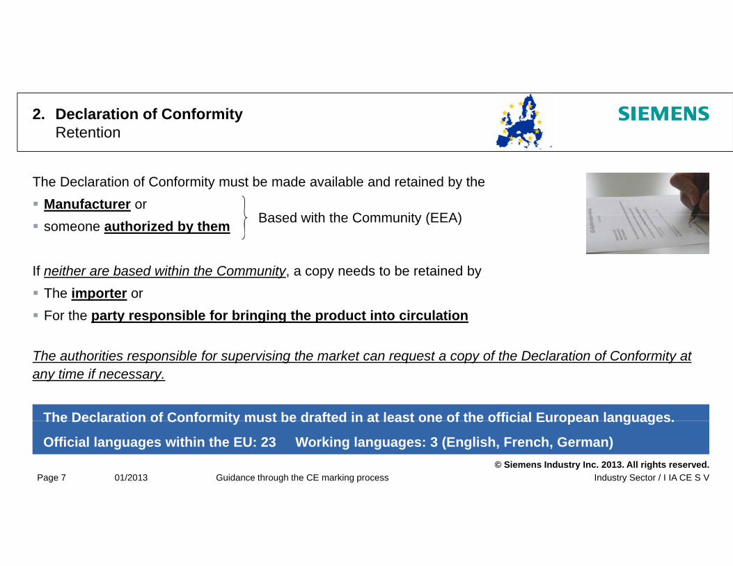
The Declaration of Conformity must be made available and retained by the Manufacturer or
B d ith th C it (EEA) someone authorized by them
If neither are based within the Community, a copy needs to be retained by
Based with the Community (EEA)
The importer or For the party responsible for bringing the product into circulation
Th th iti ibl f i i th k t t f th D l ti f C f it t
The Declaration of Conformity must be drafted in at least one of the official European languages.
The authorities responsible for supervising the market can request a copy of the Declaration of Conformity at any time if necessary.
© Siemens Industry Inc. 2013. All rights reserved.Industry Sector / I IA CE S VPage 7 01/2013 Guidance through the CE marking process
The Declaration of Conformity must be drafted in at least one of the official European languages.
Official languages within the EU: 23 Working languages: 3 (English, French, German)

3. CE marking
Marking of electrical switching devices and components with CE marking before it is brought into circulation by the manufacturer only or someone authorized by them and based within the Community
CE marking applied to the electrical switching devices and components themselves or, if this is not possible, to the packaging, the user instructions, or the warranty certificate
Marking must be clearly visible, legible, and permanent.
Minimum height 5mm with proportions retained if enlarged
© Siemens Industry Inc. 2013. All rights reserved.Industry Sector / I IA CE S VPage 8 01/2013 Guidance through the CE marking process

3. CE marking
The CE marking indicates that an electrical switching device or component:
Yes ?
Satisfies the main requirements
Has been through the conformity assessment process as defined in the Low Voltage Directive and the other directives
MachineDirective
Device isa Machine
ATEXDirective
Yes ?
Yes ?
applicable to the product
And whose free movement within the European Economic Area may only be limited/denied if there are well grounded suspicions (presumption of effectiveness)
HazardeousLocations
EMC - Directive
Markingneccessary
Yes ?
Yes ?
(presumption of effectiveness)
It is forbidden to apply markings whose meaning or design b f d ith th i d i f CE ki
Low Voltage Directive
Voltage50 … 1000 Vac75 … 1500 Vdc
Yes ?
Yes ?
© Siemens Industry Inc. 2013. All rights reserved.Industry Sector / I IA CE S VPage 9 01/2013 Guidance through the CE marking process
may be confused with the meaning or design of CE marking.

Examples of the declaration of conformity, rating plate, and the CE marking
Declaration of conformity for a SIVACON power distribution board
Example rating plate of a low-voltage switchgear and controlgear assembly –according to IEC/EN 61439IEC/EN 61439--22according to IEC/EN 61439IEC/EN 61439 22
Manufacturer: Panel building LtdManufacturer: Panel building Ltd.
Serial number: Power distribution board 12345
Date of manufacture: September 2012
S it h d t l bl li ith IEC 61439 2
© Siemens Industry Inc. 2013. All rights reserved.Industry Sector / I IA CE S VPage 10 01/2013 Guidance through the CE marking process
Switchgear and controlgear assembly complies with IEC 61439-2

Thank you for your attention!Any questions?
© Siemens Industry Inc. 2013. All rights reserved.

Introduction to the relevant IEC/EN standards for control panel designstandards for control panel design
Which standards are applicable and validpp Scope of the new IEC 61439
“Low-voltage switchgear and control gear assemblies” Scope of the IEC 60204-1 Scope o t e C 60 0
“Electrical equipment of machines”
© Siemens Industry Inc. 2013. All rights reserved.
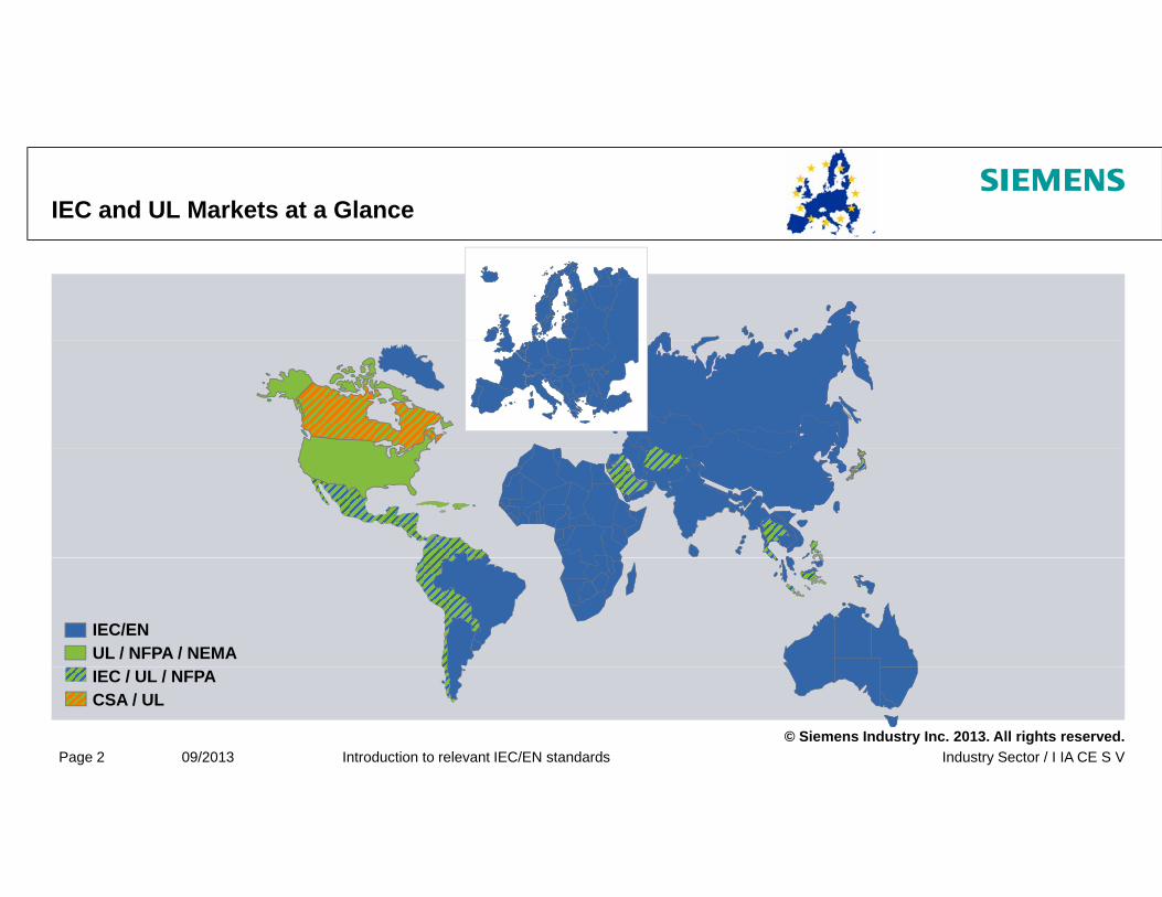
IEC and UL Markets at a Glance
IEC/ENUL / NFPA / NEMA
© Siemens Industry Inc. 2013. All rights reserved.Industry Sector / I IA CE S VPage 2 09/2013 Introduction to relevant IEC/EN standards
IEC / UL / NFPACSA / UL

Adoption of IEC standards according to local requirementsExplanation regarding use of prefixes
Publisher Standard Issue Date
NormsInternational
ISO / IECe.g. IEC 61439-1:06/2009
e.g. EN 61439-1:12/2009European Committee for
Electrotechnical Standardisation:
National NormsDIN / VDE / DKE
gMinor changes/additions acc. to region (EU)
e. g. DIN EN 61439-1:06/2010Minor changes/additions acc. to region (e.g. France)
Every nation, referring to the
CENELEC, transposes and
translates EN standards into
national standards.
Factory standards
o c a ges/add t o s acc to eg o (e g a ce)
© Siemens Industry Inc. 2013. All rights reserved.Industry Sector / I IA CE S VPage 3 09/2013 Introduction to relevant IEC/EN standards

Differences Between Europe & North America
Europe Responsibility of the manufacturer
USA / North America Responsibility of the operatorResponsibility of the manufacturer
Responsibility of the operator Protection targets are defined by
directives
Responsibility of the operator
Protection targets and requirementsare defined by laws
C tifi ti / li ti f d t Presumption of conformity with the application of harmonized standards (ISO9000 et seqq., self-certification, self-responsibility)
Certification / listing of products
Verification by independent NRTL/AHJ (third-party certification)
+ successful inspection by the
© Siemens Industry Inc. 2013. All rights reserved.Industry Sector / I IA CE S VPage 4 09/2013 Introduction to relevant IEC/EN standards
+ successful inspection by theAuthority having Jurisdiction (AHJ)

Search Path within the Sets of Standards Example done with IEC/EN standards
Compliance with EU di tiCompliance withYes / NoIEC/EN 60364-1 Low-voltage
directiveInstallation Standards
Compliance withYes / No
EU-directives
on dsA
pplic
atio
stan
dard
IEC/EN 60204-1 IEC/EN 61439-1
Pro
duct
-st
anda
rds
IEC/EN 60947-1Low-voltage
switching devices
IEC/EN 60947-2Low-voltage
circuit breakers
IEC/EN 60947-4-1Contactors,
motor starters
IEC/EN 60947-6-2Contactors,
motor starters
© Siemens Industry Inc. 2013. All rights reserved.Industry Sector / I IA CE S VPage 5 09/2013 Introduction to relevant IEC/EN standards

Official Journal of the European Union for the LVD 2006/95/ECExtract with the relevant IEC/EN standards for control panel design
© Siemens Industry Inc. 2013. All rights reserved.Industry Sector / I IA CE S VPage 6 09/2013 Introduction to relevant IEC/EN standards

IEC 60204-1 – Scope (Excerpt)Standard for electrical equipment of machines
Application of electrical, electronic and programmable electronic equipment and systems to machines not portable by hand while working, including a group of machines working together in a co-ordinated manner. Equipment covered by this part of IEC 60204 commences at the point of connection of the supply to the
electrical equipment of the machine (see 5.1). Note: The requirements for the electrical supply installation in buildings are given in the IEC 60364 series. Applicable to equipment that operate with nominal supply voltages not exceeding 1000 V AC and 1500 V Applicable to equipment that operate with nominal supply voltages not exceeding 1000 V AC and 1500 V
DC and with nominal supply frequencies not exceeding 200 Hz. Note: For higher voltages, see IEC 60204-11.
Note: The standard is aligned and more and more harmonized with the U.S. standard “NFPA79 Standard
for Industrial Machinery”
© Siemens Industry Inc. 2013. All rights reserved.Industry Sector / I IA CE S VPage 7 09/2013 Introduction to relevant IEC/EN standards
y

Examples of Machines Covered by IEC/EN 60204-1 (Annex C)
Metalworking machinery Food machinery
Leather/imitation leather goods and footwear machinery Trimming and brushing machines
Plastics and rubber machinery Printing, paper and board machinery Folding machines Wood machinery
Construction and building materials machinery Hoisting machinery (see IEC 60204-32) Transportable machineryWood machinery
Inspecting and testing machinery Assembly machines, compressors Conveyor technology, material handling
Transportable machinery Machinery for transportation of persons Mobile machinery Power-operated doors/gates
Packaging machinery Shrink-wrapping machines Textile machines, laundry machines Refrigeration and air-conditioning machines
Machines for hot metal processing Leisure machinery Tanning machinery Pumps mining and quarrying machines
© Siemens Industry Inc. 2013. All rights reserved.Industry Sector / I IA CE S VPage 8 09/2013 Introduction to relevant IEC/EN standards
Refrigeration and air conditioning machines Heating and ventilating machines
Pumps, mining and quarrying machines Agriculture and forestry machines

IEC 61439 – Scope for Low-voltage switchgear and controlgear assemblies
Parts 1 & 2 apply to switchgear and controlgear assemblies: With a rated voltage of up to 1,000 V AC or 1,500 V DC Both fixed and movable, with or without enclosureBoth fixed and movable, with or without enclosure For generating, transmitting, distributing, and converting electrical energy and controlling electrical switching
devices and components To be used under special operating conditions (e.g. on ships, railcars) associated with additional
requirements For equipping machines with the additional requirements under IEC 60204 That are individual units or series-produced
The control panel may also be assembled by a different manufacturer to the original one
The standard is intended to lay down definitions and set out the operating conditions, construction requirements, technical properties, and verification requirements!
© Siemens Industry Inc. 2013. All rights reserved.Industry Sector / I IA CE S VPage 9 09/2013 Introduction to relevant IEC/EN standards
partially comparable with the U.S. standard “UL508A standard for industrial control panels”

TerminologyLow-voltage switchgear and controlgear assembly
Low-voltage switchgear and controlgear assembly [e.g. industrial control panel]
A bl f l l lt it h d t l ith l t d i t f t l Assembly of one or several low-voltage switchgears and controlgears with related equipment for control, measurement, reporting, protection, and regulation, with all the internal electrical and mechanical connections and structural components
© Siemens Industry Inc. 2013. All rights reserved.Industry Sector / I IA CE S VPage 10 09/2013 Introduction to relevant IEC/EN standards

Thank you for your attention!Any questions?
© Siemens Industry Inc. 2013. All rights reserved.

Required verifications for IEC/EN control panelscontrol panels
Introduction to verifications Design verifications Routine verifications Routine verifications Documentation
© Siemens Industry Inc. 2013. All rights reserved.

Introduction to verificationsTerminology
Design verification:Verification of specimens of a switchgear and controlgear assembly or parts of switchgear and p g g y p gcontrolgear assemblies to show the design meets the requirements of the relevant switchgear and controlgear assembly standard
Objective:Verification of compliance with the general requirements of the IEC 61439-1 standard and the relevant IEC 61439–2….6 product standard
IEC 61439-1 §10Design verifications are to be performed by the original manufacturer of the switchgear
© Siemens Industry Inc. 2013. All rights reserved.Industry SectorPage 2 10/2013 Required verifications for IEC/EN control panels
Design verifications are to be performed by the original manufacturer of the switchgear and controlgear assembly or their performance should be agreed upon.

Introduction to verification testsTerminology
Design verification via:
Testing Tests on a specimen of a switchgear and controlgear assembly or parts of switchgear and controlgearg
Comparison
assembly or parts of switchgear and controlgear assemblies
Structured comparison of the planned design or parts of a switchgear and controlgear assembly with a referenceComparison a switchgear and controlgear assembly with a reference design, verification via testing
Design verification of set design rules or calculations based
© Siemens Industry Inc. 2013. All rights reserved.Industry SectorPage 3 10/2013 Required verifications for IEC/EN control panels
Assessment on a specimen or parts of a switchgear and controlgear assembly

Introduction to verification testsTerminology
Routine verificationVerification process to which each switchgear and controlgear assembly is subjected during and/or p g g y j gafter its manufacture to ensure it meets the requirements of the relevant switchgear and controlgear assembly standard
Objective: To identify material and manufacturing defects Ensure operability
DIN EN 61439-1 §11R ti ifi ti t b f d b th f t f th it h d
© Siemens Industry Inc. 2013. All rights reserved.Industry SectorPage 4 10/2013 Required verifications for IEC/EN control panels
Routine verifications are to be performed by the manufacturer of the switchgear and controlgear assembly.

Design verificationsVerification options in accordance with IEC 61439-1 Annex D
There are alternative processes for some design verifications. Alternative processes are treated as being equivalent.p g q The original manufacturer makes the choice.
Testing
ComparisonDesign verification via:
© Siemens Industry Inc. 2013. All rights reserved.Industry SectorPage 5 10/2013 Required verifications for IEC/EN control panels
Assessment

Design verificationsVerification options in accordance with IEC 61439-1 Annex D
Property requiring verification Verification optionsTesting Comparison Assessment
St th f t i l YES NO NO
1.) UV radiation / resistanceto exceptional heat and fire
Exceptions:
Strength of materials YES NO NO 1.)
Degree of protection of the enclosure YES NO YESClearances YES NO NOCreepage distances YES NO NO
p
2.) Short-circuit withstand strength of the protective conductor
3.) Surge voltage strength
Protection against electric shock and integrity of protective circuits
YES NO 2.) NO
Incorporation of switching devices and components NO NO YESInternal electrical circuits and connections NO NO YESTerminals for external conductors NO NO YESDielectric properties YES NO NO 3.)
Temperature rise limits YES YES YESShort-circuit withstand strength YES YES NO
© Siemens Industry Inc. 2013. All rights reserved.Industry SectorPage 6 10/2013 Required verifications for IEC/EN control panels
Electromagnetic compatibility (EMC) YES NO YESMechanical function YES NO NO

Design verification – performanceVerification of temperature rise – overview
3 Verification options: testing, comparison, assessment
a.) Testingb.) Comparisonc.) Assessment
InA
1 600 A
a.)a.)
b )*) R t i ti
1,600 A
a.)b.)
b.)c.)*
b.)*) Restrictions
630 A
© Siemens Industry Inc. 2013. All rights reserved.Industry SectorPage 7 10/2013 Required verifications for IEC/EN control panels
c.)different InA for the switchgear and controlgear assembly

Design verification – performanceVerification of temperature rise – testing
Verification via testing
Verification option for all switchgear and controlgear assemblies where InA >1 600 AVerification option for all switchgear and controlgear assemblies where InA >1,600 A
Rules for selecting test items (worst-case testing)
Rules for testing complete switchgear and controlgear assemblies
Rules for separate testing of main busbars, distribution bars, and functional units
© Siemens Industry Inc. 2013. All rights reserved.Industry SectorPage 8 10/2013 Required verifications for IEC/EN control panels

Design verification – performanceVerification of temperature rise – testing
Testing of main busbars Testing of field types
Selecting a representative arrangement
Testing of main busbars
Least suitable versions under worst-case conditions
Regardless of
Testing of field types
Least suitable versions under worst-case conditions
Valid for all versions of the field type
Fields with one
functional unit
field type but valid for all fields
Testing of field distribution bars Testing of functional units
Least suitable versions under worst-case conditions
Regardless of versions and arrangement of functional units
Least suitable versions underworst-case conditions
Valid for all versions of functional units
Fieldswith more than one
functional unit
© Siemens Industry Inc. 2013. All rights reserved.Industry SectorPage 9 10/2013 Required verifications for IEC/EN control panels
functional units but valid for all versions

Design verification – performanceVerification of temperature rise – testing
Parts of the switchgear and controlgear assembly Temperature-rise limit [K]
Table 6, IEC 61439 – applies with a max. ambient temperature ≤ 35°C
g g y p [ ]In-built switching devices and components As per specificationsTerminals for incoming/outgoing insul. conductors 70 K (e.g. 35 + 70 = 105°C)Current bars, conductors, plug-in contacts, replaceable parts Limited by:
Mechanical strength Influence on adjacent switching devices and components Limit temperature of insulating materials Connected switching devices and components Contact material for isolating contacts
Controls Metal 15 K (e g 35 + 15 = 50°C)Controls MetalInsulating material
15 K (e.g. 35 + 15 = 50 C)25 K (e.g. 35 + 25 = 60°C)
Exterior surfaces Metalexposed to the touch Insulating material
30 K (e.g. 35 + 30 = 65°C)40 K (e.g. 35 + 40= 75°C)
Plug connections Limited by incoming switching devices and components
© Siemens Industry Inc. 2013. All rights reserved.Industry SectorPage 10 10/2013 Required verifications for IEC/EN control panels
g y g g pWithin switchgear and controlgear assemblies, higher temperatures may occur at grounded metal parts if damage involving built-in switching devices and components can be ruled out.

Design verification – performanceVerification of temperature rise – testing
Ambient temperature must be between +10°C and +40°C
U f th l d th t Use of thermocouples and thermometers
The temperature-rise limit values in Table 6 must not be exceeded
Th d i ithi th it h d t l bl t k f tl The devices within the switchgear and controlgear assembly must work perfectly
© Siemens Industry Inc. 2013. All rights reserved.Industry SectorPage 11 10/2013 Required verifications for IEC/EN control panels

Design verification – performanceVerification of temperature rise – comparison
Verification is based on a comparison with a tested reference design.
Can be used for: 1. Switchgear and controlgear assembliesg g2. Busbars3. Functional units
© Siemens Industry Inc. 2013. All rights reserved.Industry SectorPage 12 10/2013 Required verifications for IEC/EN control panels
Design verification – performanceVerification of temperature rise – comparison with a switchgearand controlgear assemblyg y
The functional units must belong to the same group as the functional unit selected for testing.
Th d i t b th th t d f th t t The design must be the same as that used for the test.
The overall dimensions must be greater than or equal to those tested.
V til ti t b id ti l t b tt th th t t til ti (f d til ti t l Ventilation must be identical to or better than the test ventilation (forced ventilation or naturalconvection, identical or larger ventilation openings).
The number of internal partitions (if there are any) must not exceed the number during testing.
Power loss within the same field must not exceed that during testing.
© Siemens Industry Inc. 2013. All rights reserved.Industry SectorPage 13 10/2013 Required verifications for IEC/EN control panels
Design verification – performanceVerification of temperature rise – comparison with busbars
Rated values for aluminum bars also apply to copper bars, but not vice versa.
C i ith t t it b d th f ll i it i d ti f f th h i ht Comparison with test items based on the following criteria: reduction of one or more of the height, width, number of bars per conductor, but with
1. The same bar arrangement2 Th di t b t t f d t2. The same distances between centers of conductors3. The same enclosure and4. The same busbar compartment (if there is one)
If the cross section which has been tested is also smaller than the one to be derived, the rated values for the versions in between may be determined via interpolation.
© Siemens Industry Inc. 2013. All rights reserved.Industry SectorPage 14 10/2013 Required verifications for IEC/EN control panels

Design verification – performanceVerification of temperature rise – comparison with functional units
Rated currents must be calculated for all functional units within the group. The reduction factor must be determined for each functional unit. The rated current for each untested functional unit within the group is the highest possible current
for this functional unit multiplied by the reduction factor for the tested version for the group.Functional units - replacing devices p gA device may be replaced by a similar device from a different series than the one used for the original verification, providing The power loss and temperature rise for the terminals of the device during testing are less than or e po e oss a d te pe atu e se o t e te a s o t e de ce du g test g a e ess t a o
equal to its product standard. Also, the physical arrangement within the functional unit and the rating for the functional unit must
remain the same.
© Siemens Industry Inc. 2013. All rights reserved.Industry SectorPage 15 10/2013 Required verifications for IEC/EN control panels

Design verification – performanceVerification of temperature rise – Assessment
2 calculation methods are allowed:1. InA ≤ 630 AnA
Comparing the resulting power loss with the power loss associated with the enclosure
2. InA ≤ 1600 ACalculating the power loss and radiation via the enclosure in accordance with IEC 60890for switchgear and controlgear assemblies InA> 630 A to 1600 A (maximum of 3 internal partitions)
Generally speaking: The rated current for the circuits may not exceed 80% of the conventional thermal rated currents for
switchgear and electrical switching devices and components in free air within the circuit.
© Siemens Industry Inc. 2013. All rights reserved.Industry SectorPage 16 10/2013 Required verifications for IEC/EN control panels
All conductors must have a minimum cross section equivalent to 125% of the permissible rated current.

Design verification – performanceVerification of short-circuit withstand strength
Verification of rated currents for short circuits via Comparison with a reference construction (checklist or calculation)p ( ) TestingVerification of the short-circuit withstand strength of circuits is not required for:a) Switchgear and controlgear assemblies with a rated short-term withstand current Icw or aa) Switchgear and controlgear assemblies with a rated short-term withstand current Icw or a
conditional rated short-circuit current Icc with a root mean square value of 10 kA at the most;b) Switchgear and controlgear assemblies or circuits of switchgear and controlgear assemblies,
protected by current-limiting devices, whose peak-let through current at the highest permissible p otected by cu e t t g de ces, ose pea et t oug cu e t at t e g est pe ss b euninfluenced short-circuit current at the in-feed terminals of the switchgear and controlgear assembly does not exceed 17 kA;
c) For auxiliary circuits: UN ≥ 110 V, PN ≤ 10 kVA and uk ≥ 4%
© Siemens Industry Inc. 2013. All rights reserved.Industry SectorPage 17 10/2013 Required verifications for IEC/EN control panels
N N
UN < 110 V, PN ≤ 1.6 kVA and uk ≥ 4%

Design verification – performanceVerification of short-circuit withstand strength is not required – case a.)
A rated short-term current tolerance Icwor conditional rated short-circuit current Icc
I f d
≤ 10 kA
Field A Field B
InfeedOutgoing feeders
© Siemens Industry Inc. 2013. All rights reserved.Industry SectorPage 18 10/2013 Required verifications for IEC/EN control panels
Icp ≤ 10kA

Design verification – performanceVerification of short-circuit withstand strength is not required – case b.)
Overcurrent protection devices:
Ipeak ≤ 17kA at Icp ≥ 10kA
I f d
Field A Field B
InfeedOutgoing feeders
© Siemens Industry Inc. 2013. All rights reserved.Industry SectorPage 19 10/2013 Required verifications for IEC/EN control panels
Icp ≥ 10kA

Design verification – performanceVerification of short-circuit withstand strength is not required – case c.)
Auxiliary circuits:
UN ≥ 110 V PN ≤ 10 kVAUN ≥ 110 V, PN ≤ 10 kVA and uk ≥ 4%
UN < 110 V, PN ≤ 1.6 kVA Auxiliary circuits
and uk ≥ 4%
I f d
Field A Field B
InfeedOutgoing feeders
© Siemens Industry Inc. 2013. All rights reserved.Industry SectorPage 20 10/2013 Required verifications for IEC/EN control panels

Design verification – performanceVerification of short-circuit withstand strength
Example with SIMARIS curves: NH fuse 3NA..., 200 A,, ,
Icu = 120 kA Icp = 50 kA Ipeak = 16.2 kA
Ipeak ≤ 17 kANo verification of the short-circuit
withstand strength necessary!t sta d st e gt ecessa y
© Siemens Industry Inc. 2013. All rights reserved.Industry SectorPage 21 10/2013 Required verifications for IEC/EN control panels

Design verification – performanceVerification of short-circuit withstand strength
Example with SIMARIS curves: Circuit breaker 3RV1042, 50 A,, ,
Icu = 100 kA Icp = 30 kA Ipeak = 16.2 kA
Ipeak ≤ 17 kANo verification of the short-circuit
withstand strength necessary!t sta d st e gt ecessa y
© Siemens Industry Inc. 2013. All rights reserved.Industry SectorPage 22 10/2013 Required verifications for IEC/EN control panels

Design verification – performanceVerification of short-circuit withstand strength – comparison
1. Comparison based on a checklist Comparison using 10 questions in the IEC 61439 checklistp g q If an element in the checklist is not satisfied, then comparison based on calculations or testing
2 Comparison using calculation (only for busbars!)2. Comparison using calculation (only for busbars!) Verification of the short-circuit withstand strength of busbar arrangements via comparison
based on calculations (Annex P IEC 61439) and Points 6 8 9 and 10 in the checklist also need to be satisfied
Notice: Comparison may only be based on a reference design which has been tested
Points 6,8,9, and 10 in the checklist also need to be satisfied
© Siemens Industry Inc. 2013. All rights reserved.Industry SectorPage 23 10/2013 Required verifications for IEC/EN control panels
p y y galready!

Design verification – performanceVerification of short-circuit withstand strength – testing
Verification via testing;
Where the design is the same only one functional unit needs to be testedWhere the design is the same, only one functional unit needs to be tested.
Only one bar needs to be tested if the rest have a similar configuration.
Circuits must be tested to the highest thermal and dynamic standards.
Testing of main circuits
Testing of neutral conductors (at least 60% of external conductor current)
Testing of protective circuit (at least 60% of external conductor current)
...
© Siemens Industry Inc. 2013. All rights reserved.Industry SectorPage 24 10/2013 Required verifications for IEC/EN control panels

Design verification – performanceElectromagnetic compatibility (EMC)
Generally speaking:Verification is based onVerification is based on Assessment (of constructional requirements – Chapter 8) Tests as per Annex J
Verification based on tests is not required if an Assessment finds that: Switching devices and components are designed for the specified environment. Installation and wiring have respected manufacturer specifications.In all other cases testing as per Annex J.10.12
© Siemens Industry Inc. 2013. All rights reserved.Industry SectorPage 25 10/2013 Required verifications for IEC/EN control panels
The requirements of EMCD 2004/104/EC for the control panel are thus fulfilled.
Design verification – performanceElectromagnetic compatibility (EMC)
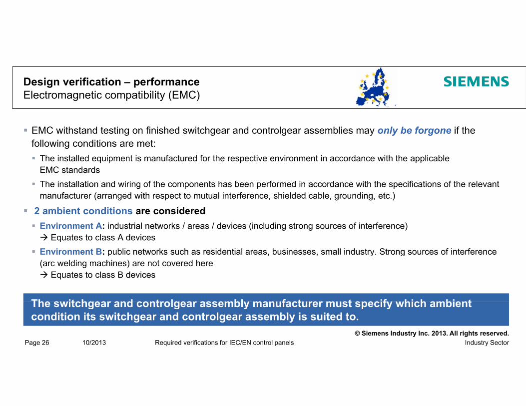
EMC withstand testing on finished switchgear and controlgear assemblies may only be forgone if the following conditions are met: The installed equipment is manufactured for the respective environment in accordance with the applicable
EMC standards The installation and wiring of the components has been performed in accordance with the specifications of the relevant
manufacturer (arranged with respect to mutual interference, shielded cable, grounding, etc.)
2 ambient conditions are considered Environment A: industrial networks / areas / devices (including strong sources of interference) Equates to class A devices
Environment B: public networks such as residential areas businesses small industry Strong sources of interference Environment B: public networks such as residential areas, businesses, small industry. Strong sources of interference (arc welding machines) are not covered here Equates to class B devices
The switchgear and controlgear assembly manufacturer must specify which ambient
© Siemens Industry Inc. 2013. All rights reserved.Industry SectorPage 26 10/2013 Required verifications for IEC/EN control panels
The switchgear and controlgear assembly manufacturer must specify which ambient condition its switchgear and controlgear assembly is suited to.

Design verification – performanceElectromagnetic compatibility (EMC)
Interference immunitySwitchgear and controlgear assemblies without installed
l t i i t id d i t i t f d l ti ditielectronic equipment are considered immune to interference under normal operating conditions. No verification necessary for this Furthermore these devices do not usually have any specification on the environment to which
they are best suitedy
Emitted interferenceSwitchgear and controlgear assemblies without installed electronic equipment only produce
l i i f d i i hi i H hi i l f felectromagnetic interference during switching operations. However, this is only for a few milliseconds. It is also a part of the normal electromagnetic environment. No verification necessary for this Furthermore these devices do not usually have any specification on the environment to which
© Siemens Industry Inc. 2013. All rights reserved.Industry SectorPage 27 10/2013 Required verifications for IEC/EN control panels
y y pthey are best suited

Documentation
A test report must be created for the conducting of verifications as per DIN EN 61439-1.
Chapter 10.1
verifications as per DIN EN 61439 1.
"The reference design, the number of switchgear and controlgear assemblies used for the verifications, or parts of these, the choice of verification methods, providing they are applicable, and the sequence of verifications are the responsibility of the original manufacturer.
The data used, the calculations, and the comparisons conducted when verifying the
© Siemens Industry Inc. 2013. All rights reserved.Industry SectorPage 28 10/2013 Required verifications for IEC/EN control panels
switchgear and controlgear assemblies are to be documented in a test report."

Thank you for your attention!Any questions?
© Siemens Industry Inc. 2013. All rights reserved.

Protective measures acc. IEC/EN standardsstandards
© Siemens Industry Inc. 2013. All rights reserved.

Protective Measures – OverviewIEC 60364-4-41 – Part 410
Protective measures
Protection againstdirect contactdirect contact
(basic protection)
Protection against indirect contactindirect contact(fault protection)
Protection againstdirect and indirectdirect and indirect
contact
Insulation oflive parts
Enclosure orcasing
Protectiveextra-low voltage
Functionalextra-low voltage
1 2
Obstacles(e.g. barriers)
Distance Limitation of thedischarge energy
3
© Siemens Industry Inc. 2013. All rights reserved.Industry SectorPage 2 10/2013 Required verifications for IEC/EN control panels
Disconnectionor signaling
Protectiveinsulation
Earth-free, localequipotential bonding
Electricalseparation
Non-conductiveenvironment
3

Protective Measures – IEC/EN 60204-1§ 6.2.3 Protection by Insulation of Live Parts 1
Live parts have to be completely encased with insulation. Such insulation must only be removable by way of destruction. The insulation must be capable of withstanding the mechanical, chemical, electrical and thermal
stresses to which it can be subjected under normal operating conditions.Note: Coats of paint, varnish, lacquer, enamel and similar products alone are generally considered to be inadequate for protection against electric shockbe inadequate for protection against electric shock.
Examples include cables/lines and electrical components which are completely encased with insulating material.
This basic insulation: must correspond to the respective overvoltage categories
(compliance with clearances and creepage distances).
© Siemens Industry Inc. 2013. All rights reserved.Industry SectorPage 3 10/2013 Required verifications for IEC/EN control panels
must be sufficiently ageing-resistant for the respective service life of the insulated part.

Protective Measures – EN 60204-1§ 6.2.2 Protection by Enclosures (Casings) 2
Live parts must be installed inside enclosures which offer protection against direct contact of at least IP2X or IPXXB.
If the top surfaces of the enclosures are easily accessible, the top surfaces must at least offer degree of protection IP4X or IPXXD.
IP2x or IPxxB: Also referred to as finger-proofIP4x or IPxxD: Also referred to as wire-proof (poke-proof)
Opening of the enclosure (i.e. opening of doors, lids, covers and the like) must only be possible under certain conditions. see next slide
© Siemens Industry Inc. 2013. All rights reserved.Industry SectorPage 4 10/2013 Required verifications for IEC/EN control panels

Protective Measures – IEC/EN 60204-1§ 6.2.2 Protection by Enclosures 2
a)a) With keys or toolsWith keys or tools Access only for electrically instructed persons, electrically skilled persons.Live parts which may be touched during resetting, adjustment, etc. must be at least IP2x (IPxxB). Inside of doors at least IP1x or IPxxA.
b)b) Disconnection of live partsDisconnection of live partsbefore the enclosure can be opened, e.g.: Door-coupling operating devicesThe door can only be opened when the disconnecting device is openThe door can only be opened when the disconnecting device is openThe door can only be opened when the disconnecting device is openThe door can only be opened when the disconnecting device is openThe disconnecting device can only be switched ON when door is closedThe disconnecting device can only be switched ON when door is closedAll parts which remain energized after disconnecting must be protected against direct contact (at least IP2x / IPxxB). Such parts must be marked with a warning sign (also see identification of conductors by
l )color).
c)c) Without keys or tools or without disconnectionWithout keys or tools or without disconnectionwhen all live parts at least correspond to IP2x (IP4x) or IPxxB (IPxxD). Barriers must only be removable by means of toolsby means of tools
© Siemens Industry Inc. 2013. All rights reserved.Industry SectorPage 5 10/2013 Required verifications for IEC/EN control panels
Barriers must only be removable by means of toolsby means of tools.If barriers are removable without tools, the respective live parts have to be disconnected disconnected automaticallyautomatically.
Protective Measures – IEC/EN 60204-1§ 6.3.3 Protection by Automatic Disconnection 3
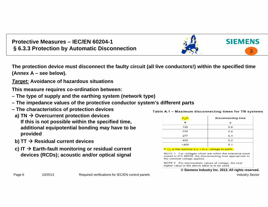
The protection device must disconnect the faulty circuit (all live conductors!) within the specified time (Annex A – see below).Target: Avoidance of hazardous situationsThis measure requires co-ordination between:– The type of supply and the earthing system (network type)– The impedance values of the protective conductor system’s different partsThe impedance values of the protective conductor system s different parts– The characteristics of protection devices
a) TN Overcurrent protection devicesIf this is not possible within the specified time, additional equipotential bonding may have to beadditional equipotential bonding may have to be provided
b) TT Residual current devicesc) IT Earth-fault monitoring or residual current
d i (RCD ) ti d/ ti l i l
© Siemens Industry Inc. 2013. All rights reserved.Industry SectorPage 6 10/2013 Required verifications for IEC/EN control panels
devices (RCDs); acoustic and/or optical signal

Protective Measures – IEC/EN 60204-1§ 6.3 Protection Against Indirect Contact
In generalIn generalServes the avoidance of hazardous situations in the event of an insulation fault between live parts and bodies.At least one of the following measures has to be taken for every circuit or every part of the electrical equipment:
Automatic disconnection of the supply before any contact may become– Automatic disconnection of the supply before any contact may become hazardous (depending on voltage and duration of contact)
– Measures which prevent the occurrence of a touch voltage
Note:Note:The risk (for persons and livestock) of harmful effects as a result of a touch voltage depends on the voltage level and the duration of exposure.For protection classes of the equipment and protective measures see IEC/EN 61140
© Siemens Industry Inc. 2013. All rights reserved.Industry SectorPage 7 10/2013 Required verifications for IEC/EN control panels
For protection classes of the equipment and protective measures, see IEC/EN 61140.
Thank you for your attention!Any questions?
© Siemens Industry Inc. 2013. All rights reserved.

Planning efficiency, helpful tools for CAD/CAE systems andfor CAD/CAE systems and documentation
SIMARIS software tools "My Documentation Manager" My Documentation Manager CAx download manager
© Siemens Industry Inc. 2013. All rights reserved.

SIMARIS software tools
SIMARIS design: Network calculations and calculating
short-circuit currents
SIMARIS curves:Vi li i d l ti Visualizing and evaluating characteristic curves
© Siemens Industry Inc. 2013. All rights reserved.Industry Sector / I IA CE S VPage 2 01/2013 Tools for assisting with documentation
Download: www.siemens.com/simaris

SIMARIS designFunctionality
Dimensioning electrical networks based on real products from medium-voltage through to consumer-level, including an automatic selection of suitable equipment Dimensioning is conducted according to the recognized rules of technology and applicable standards
(VDE, IEC) Open definition of the types of mains operation and switching states Calculation of the short circuit current, load flow,Calculation of the short circuit current, load flow,
voltage drop and energy balance Consideration of the required personal, short-circuit,
and overload protection Consideration of the required lightning and
surge protection possible Representation of the busbar trunking systems for
power transmission and distribution
© Siemens Industry Inc. 2013. All rights reserved.Industry Sector / I IA CE S VPage 3 01/2013 Tools for assisting with documentation
p Different output versions for documentation

SIMARIS designVersions
All functions for the di i i f th
Special electrotechnical f ti
Online registrationdimensioning of the electrical power distribution
functions
SIMARIS design Professional For a nominal charge
SIMARIS design -- Free of charge
© Siemens Industry Inc. 2013. All rights reserved.Industry Sector / I IA CE S VPage 4 01/2013 Tools for assisting with documentation

SIMARIS curvesFunctions
Visualization and evaluation of the tripping characteristics of low-voltage protective devices and fuses (IEC), including an option for the simulation of device settings Visualization of cut-off current and cut-off energy characteristics Product selection overview per order number or selection guide Saving of selected devices as favorites Saving of several characteristic curves including settings as a
complete project Consideration of country-specific product portfolios User friendly documentation User-friendly documentation
© Siemens Industry Inc. 2013. All rights reserved.Industry Sector / I IA CE S VPage 5 01/2013 Tools for assisting with documentation

SIMARIS curvesSIMARIS curves 2.x characteristic curves display
Product search using
Display of tripping, cut-off current, and cut-off power characteristicsg
order number or catalog
characteristics
Simulation of device settings
© Siemens Industry Inc. 2013. All rights reserved.Industry Sector / I IA CE S VPage 6 01/2013 Tools for assisting with documentation
CAx download manager – Your information archive
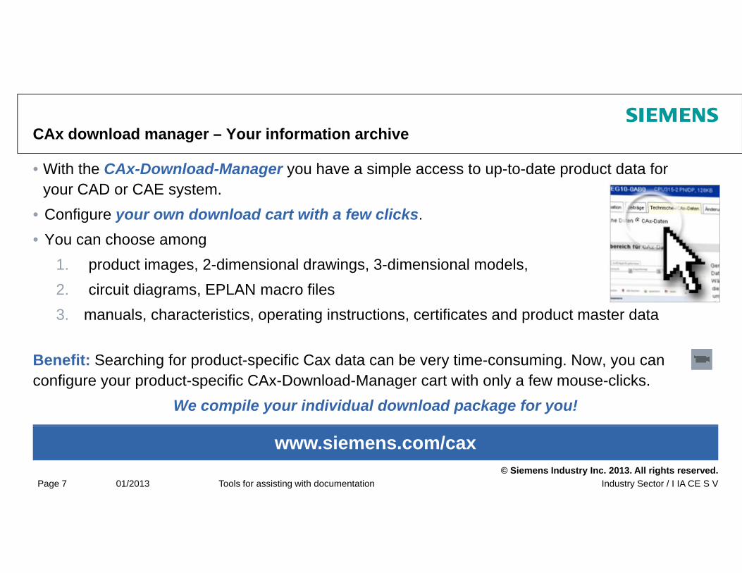
• With the CAx-Download-Manager you have a simple access to up-to-date product data for your CAD or CAE system.
• Configure your own download cart with a few clicksConfigure your own download cart with a few clicks. • You can choose among
1. product images, 2-dimensional drawings, 3-dimensional models, 2 circuit diagrams EPLAN macro files2. circuit diagrams, EPLAN macro files3. manuals, characteristics, operating instructions, certificates and product master data
B fit S hi f d t ifi C d t b ti i NBenefit: Searching for product-specific Cax data can be very time-consuming. Now, you can configure your product-specific CAx-Download-Manager cart with only a few mouse-clicks.
We compile your individual download package for you!
© Siemens Industry Inc. 2013. All rights reserved.Industry Sector / I IA CE S VPage 7 01/2013 Tools for assisting with documentation
www.siemens.com/cax

CAx download manager – Your information archiveCAx data types – Types of information
Product graphic3D model
Operating travel diagram
Product data sheet Operating instructions Commercial data
Operating travel diagram (only relevant for position
switches)
Technical data
2D dimension drawing
Terminal connection diagram
EPLAN macros
Manual
C
Internal circuit diagramCharacteristic Certificates/
approvals
© Siemens Industry Inc. 2013. All rights reserved.Industry Sector / I IA CE S VPage 8 01/2013 Tools for assisting with documentation
Product: CAx data curves approvals

MDMMy Documentation Manager – Call up options
My documentation manager Example for a customized manual
© Siemens Industry Inc. 2013. All rights reserved.Industry Sector / I IA CE S VPage 9 01/2013 Tools for assisting with documentation
www.siemens.com/mydocumentationmanager

MDMMy Documentation Manager – Function
"My documentation Manager" is an online service for customizing existing manuals to your individual
i t b bi i i lrequirements by combining or rearranging manuals, chapters or text blocks even in different languages.
BenefitsBenefits1. You can compile your manual to include all
information in all available languages that you have selected at random.
2. You can give the manual a customized layout. 3. You can subscribe to an update service so that all
parts of the documents you have incorporated into your personalized manual will be updated
© Siemens Industry Inc. 2013. All rights reserved.Industry Sector / I IA CE S VPage 10 01/2013 Tools for assisting with documentation
your personalized manual will be updated automatically in case of changes.

Thank you for your attention!Any questions?
© Siemens Industry Inc. 2013. All rights reserved.
Support and further information
Information and recommendations
CAx Download Manager and My Documentation Manager
© Siemens Industry Inc. 2013. All Rights Reserved.

Information and Recommendations Further Information Sources
Further information Configuration document; Safety applications / Safety Evaluation Tool: UL Guidelines “Industrial control panels for
North America”
Product catalog “Industrial controls”
www.siemens.com/safety-evaluation-tool www.usa.siemens.com/safety
Further UL links:gwww.usa.siemens.com/controls www.ul.com
www.ul.com/database www.nfpa.org www.newapproach.org
Further CE websites:www.newapproach.org
© Siemens Industry Inc. 2013. All Rights Reserved.Industry SectorPage 2 Issue 10/2013
Siemens UL/IEC/CE website www.usa.siemens.com/controlpaneldesign
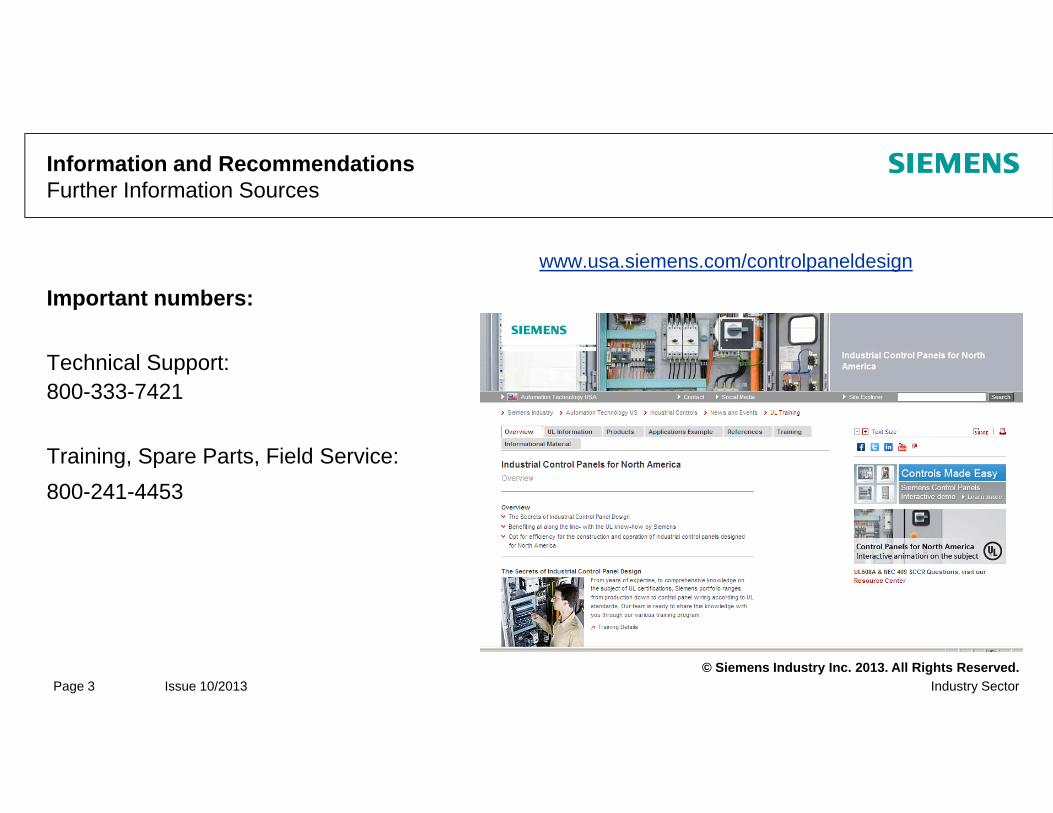
Information and Recommendations Further Information Sources
Important numbers:www.usa.siemens.com/controlpaneldesign
p
Technical Support: 800-333-7421
Training, Spare Parts, Field Service:800-241-4453
© Siemens Industry Inc. 2013. All Rights Reserved.Industry SectorPage 3 Issue 10/2013
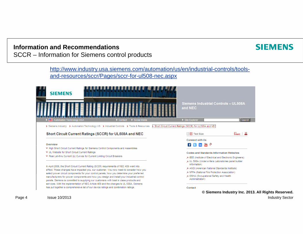
Information and Recommendations SCCR – Information for Siemens control products
http://www.industry.usa.siemens.com/automation/us/en/industrial-controls/tools-and-resources/sccr/Pages/sccr-for-ul508-nec.aspx
© Siemens Industry Inc. 2013. All Rights Reserved.Industry SectorPage 4 Issue 10/2013

UL Database www.ul.com/database
© Siemens Industry Inc. 2013. All Rights Reserved.Industry SectorPage 5 Issue 10/2013