introduction to b&w mpower™ program iaea … projects = cost/schedule certainty broad industry...
TRANSCRIPT

.1© 2011 Babcock & Wilcox Nuclear Energy, Inc. All rights reserved© 2011 Babcock & Wilcox Nuclear Energy, Inc. All rights reserved
Introduction to B&W mPower™ Program
IAEA Interregional Workshop
Vienna, Austria
July 7, 2011
Doug LeeBabcock & Wilcox Company

.2© 2011 Babcock & Wilcox Nuclear Energy, Inc. All rights reserved 2
Outline
• Introduction
• Plant layout
• Integral reactor design
• Safety concept
• Systems
• Development testing
• Implications from Fukushima
• Lead plant deployment
• Conclusion

.3© 2011 Babcock & Wilcox Nuclear Energy, Inc. All rights reserved 3
Alliance between B&W and Bechtel
Risk sharing with 90/10 current ownership
300+ FTE development team
Technology and project execution
Turnkey projects = cost/schedule certainty
Broad industry engagement
Investment from 15 member Consortium
26 member Industry Advisory Council
Goal is to deploy lead plant by 2020
Industry side of public-private partnership
Platform for industry cost/risk sharing
Nebraska Electric G&T Cooperative
Hoosier Energy Rural Electric Cooperative, Inc.
Generation mPower Industry Consortium
Industry Partners
Industry Advisory CouncilIncludes Consortium members above plus:
AEPDayton Power & LightDuke EnergyExelonNPPDVattenfall
Bruce PowerDominionEntergyMidAmericanProgress Energy
www.generationmpower.com
.4© 2011 Babcock & Wilcox Nuclear Energy, Inc. All rights reserved 4
The Babcock & Wilcox Companyis a leader in clean energy technology and services
for the nuclear and fossil power markets
.4
2010: $2.7B revenue and $5.2B backlog

.5© 2011 Babcock & Wilcox Nuclear Energy, Inc. All rights reserved 5
Bechtel Power
• Over 70 years in the power business
• Over 60 years in nuclear power
• Over 200,000 MW of completed projects
Nuclear: 74,000 MW
Fossil: 118,000 MW/445 units
Hydro: 26,000 MW/155 units
2001–2006: 30,200 MW online in 14 countries
20 years of gasification/IGCC experience
28 CT cogen plants, 5,200 MW; 12 solid fuel cogens
Integrated power/desalination; waste-to-energy
• Over 15,000 MW of active, new generation power projects
• 25,000 employees with nuclear experience
©2011 Bechtel Power Corporation. All rights reserved.

.6© 2011 Babcock & Wilcox Nuclear Energy, Inc. All rights reserved 6
Integrated Supply Chain
• Multiple sources for forgings and plate
• Component fabrication
Mt. Vernon, Indiana
Barberton, Ohio
Cambridge, Ontario, Canada
• Fuel fabrication
Lynchburg, Virginia
• Control rod drive fabrication
Euclid, Ohio
Critical NSSS Components… manufactured in existing B&W facilities

.7© 2011 Babcock & Wilcox Nuclear Energy, Inc. All rights reserved 7
Goal and Value Proposition
Develop and deploy, by 2020, an SMR that offers:
Lower Capital Cost
Schedule & Cost Certainty
Competitive LCOE Pricing
Within the constraints of:
Proven: GEN III+, established NRC regulation
Safe: Robust margins, passive safety
Practical: Standard fuel, construction and O&M
Benign: Underground, small footprint

.8© 2011 Babcock & Wilcox Nuclear Energy, Inc. All rights reserved 8
High-Level Requirements• 125 MWe Nominal Output per Module and 60-Year Plant Life
• NSSS Forging Diameter Allows Readily Available Forgings and Unrestricted
Rail Shipment
• Passive Safety Requirements – Emergency (Diesel) Power Not Required
Minimize Primary Coolant Penetrations, Maximize Elevation of Penetrations
Large Reactor Coolant Inventory
Low Core Power Density
• Standard Fuel (less than 5% U235)
• Long Fuel Cycle, 4+ Year Core Life
• Spent Fuel Storage on Site for Life of Plant
• No Soluble Boron in Primary System for Normal Reactivity Control
• Conventional/Off-the-Shelf Balance of Plant Systems and Components
• Accommodate Air-Cooled Condensers as well as Water-Cooled Condensers
• Flexible Grid Interface (50 Hz or 60 Hz)
• Digital Instrumentation and Controls Compliant with NRC Regulations
.9© 2011 Babcock & Wilcox Nuclear Energy, Inc. All rights reserved 9.9
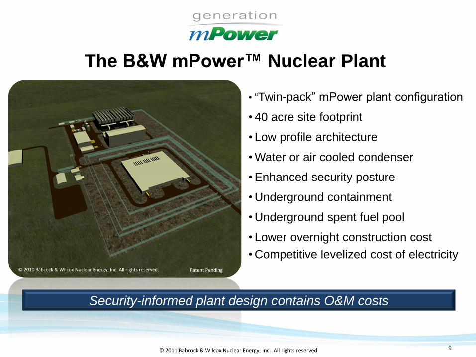
• “Twin-pack” mPower plant configuration
• 40 acre site footprint
• Low profile architecture
• Water or air cooled condenser
• Enhanced security posture
• Underground containment
• Underground spent fuel pool
• Lower overnight construction cost
• Competitive levelized cost of electricity© 2010 Babcock & Wilcox Nuclear Energy, Inc. All rights reserved. Patent Pending
The B&W mPower™ Nuclear Plant
Security-informed plant design contains O&M costs

.10© 2011 Babcock & Wilcox Nuclear Energy, Inc. All rights reserved 10
Integral Reactor
• Simplified – Integrated, Pressurized Water Reactor
• Internal Components to Minimize Penetrations
Control Rod Drives – No rod ejection
Coolant Pumps – Not safety related
• Control Rods versus Boron Shim
• Load Following Capability – Up to 10%/Min
• Passive Safety
No safety-related emergency diesel generators
No core uncovery during design basis accident (small break
LOCA)
• Performance of Critical Functions by Multiple Systems for Improved
Reliability and Plant Safety
• Multiple Module Plants – BOP Equipment Not Shared

.11© 2011 Babcock & Wilcox Nuclear Energy, Inc. All rights reserved 11
Pressurizer
Steam Generator Tubes
Reactor Coolant
Pumps
Control Rod Drive
Mechanisms
Core
Steam Outlet
Feedwater Inlet
Integral Reactor Arrangement
Primary Loop Secondary Loop
Central Riser
Steam
Feedwater

.12© 2011 Babcock & Wilcox Nuclear Energy, Inc. All rights reserved 12
Key Features of the Integral RCS
Feature B&W 177 Typical Gen 3 PWR
B&W mPower
Feature B&W 177 Typical Gen 3 PWR
B&W mPower
Rated Core power (MWth) 2568 3415 425
Core average linear heat rate (kWth/m) 18.7 18.7 11.5
Average flow velocity through the core
(m/s)
4.8 4.8 2.5
RCS volume (m3) 325 272 91
RCS volume to power ratio (m3/MWth) 0.14 0.08 0.21
Maximum LOCA area (m2) * 1.3 1.0 0.009
* Assumes double ended break
RCS volume and small break sizes allow simplification of RCS safety systems
Feature B&W 177 Typical Gen 3 PWR
B&W mPower
Rated Core power (MWth) 2568 3415 425
Core average linear heat rate (KWth/m) 18.7 18.7 11.5
Average flow velocity through the core
(m/s)
4.8 4.8 2.5
RCS volume (m3) 325 272 91
RCS volume to power ratio (m3/MWth) 0.14 0.08 0.21
Maximum LOCA area (m2) * 1.3 1.0 0.009
RCS volume/LOCA area ratio (m3 /m2) 250 270 310,000
.13© 2011 Babcock & Wilcox Nuclear Energy, Inc. All rights reserved 13
• Ensure that assemblies are mechanically designed to remain leak tight and maintain structural integrity under all possible conditions
• Load enough fuel inventory to accommodate a 4 year operating cycle at a capacity factor of > 95%
• Optimize fuel assembly design to maximize fuel utilization
• Maintain conservative peaking factors and linear heat rate throughout the operating cycle
• Ensure a shutdown margin of > 1% keff/keff under the most reactive conditions and highest worth CRA cluster stuck out
• Meet a MDNBR > 1.3 for limiting thermal-hydraulic conditions and confirm via unique CHF correlation
Design Objectives – Core and Fuel Assembly

.14© 2011 Babcock & Wilcox Nuclear Energy, Inc. All rights reserved 14
• 69 fuel assemblies
• < 5 wt% 235U enrichments
• No soluble boron for control
• Axially graded BPRs
• Gd2O3 spiked rods
• Control rod sequence exchanges
• AIC and B4C control rods
• 3% shutdown margin
Core Design Features

.15© 2011 Babcock & Wilcox Nuclear Energy, Inc. All rights reserved 15
Fuel Mechanical Design Features
15
Shortened and Simplified Conventional Fuel Assembly Design
Conventional 17x17 design
Fixed grid structural cage
Design optimized for mPower
Upper End
Fitting
End Grid
Mid Grid
17 x 17 Square Array
Control Rod Guide Tube
End Grid
Lower End Fitting

.16© 2011 Babcock & Wilcox Nuclear Energy, Inc. All rights reserved 16
Auxiliary Fluid Systems
Reactor Coolant Inventory and Purification (RCIPS)• Controls the reactor coolant volume by compensating for coolant contraction or
expansion
• Provides hydraulic pressure to CRDM
• Maintains reactor coolant activity at the desired level by removing corrosion and fission products
• Injects chemicals into the RCS to control coolant chemistry and minimize corrosion
• Removes decay heat during normal shutdown and plant cooldown
• Provides for reactor cavity fill
• Provides a means for transferring fluids and gases to the radioactive waste processing system
• Provides RCS pressure control by supplying spray flow to the pressurizer
Component Cooling Water• Supporting system for RCIPS by transferring heat to the chilled water system

.17© 2011 Babcock & Wilcox Nuclear Energy, Inc. All rights reserved 17.17
• Low Core Linear Heat Rate Low Power Density Reduces Fuel and Clad Temperatures During
Accidents
Low Power Density Allows Lower Flow Velocities that Minimize
Flow Induced Vibration Effects
• Large Reactor Coolant System Volume Large RCS Volume Allows More Time for Safety System Response
in the Event of an Accident
More Coolant Is Available During a Small Break LOCA Providing
Continuous Cooling to Protect the Core
• Small Penetrations at High Elevation High Penetration Locations Increase the Amount of Coolant Left in
the Vessel after a Small Break LOCA
Small Penetrations Reduce Rate of Energy Release to
Containment Resulting in Lower Containment Pressures
Inherent Safety Features
CONFIDENTIAL AND PROPRIETARY TO B&W
.18© 2011 Babcock & Wilcox Nuclear Energy, Inc. All rights reserved 18
ECCS Safety Functions
• Passively removes core heat following certain anticipated
operational occurrences and analyzed accidents
• Passively reduces containment pressure and temperature
following certain analyzed accidents
• Provides an alternate means of reactivity control for beyond
design basis accidents (i.e. ATWS)
• Provides a barrier to the release of fission products to the
environment
.19© 2011 Babcock & Wilcox Nuclear Energy, Inc. All rights reserved 19
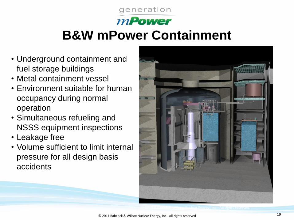
B&W mPower Containment
• Underground containment and
fuel storage buildings
• Metal containment vessel
• Environment suitable for human
occupancy during normal
operation
• Simultaneous refueling and
NSSS equipment inspections
• Leakage free
• Volume sufficient to limit internal
pressure for all design basis
accidents
© 2010 Babcock & Wilcox Nuclear Energy, Inc., All rights reserved.
.20© 2011 Babcock & Wilcox Nuclear Energy, Inc. All rights reserved 20
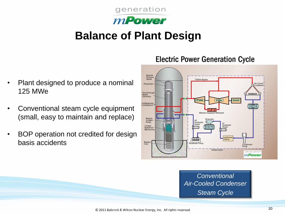
Balance of Plant Design
• Plant designed to produce a nominal
125 MWe
• Conventional steam cycle equipment
(small, easy to maintain and replace)
• BOP operation not credited for design
basis accidents
Conventional
Air-Cooled Condenser
Steam Cycle
© 2011 Babcock & Wilcox Nuclear Energy, Inc. All rights reserved.
.21© 2011 Babcock & Wilcox Nuclear Energy, Inc. All rights reserved 21
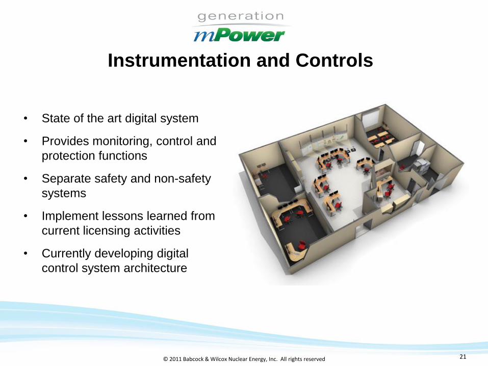
• State of the art digital system
• Provides monitoring, control and
protection functions
• Separate safety and non-safety
systems
• Implement lessons learned from
current licensing activities
• Currently developing digital
control system architecture
Instrumentation and Controls

.22© 2011 Babcock & Wilcox Nuclear Energy, Inc. All rights reserved 22
I&C Philosophy
• Highly-Reliable, Integrated and Scalable Digital I&C System
• I&C System Must Have Highest Degree of Licensing Certainty
Complies with All Regulatory, URD Requirements
Minimizes Regulatory Challenges with Digital I&C…Cyber-security, Diversity,
Independence
• Integrated, Modernized Human-Factored Design
• High Level of Plant Automation
Control of Startup, Shutdown, Load Following…support staffing plan
• Deliver Comprehensive O&M Strategy
Use of commercially-available components
Managed obsolescence

.23© 2011 Babcock & Wilcox Nuclear Energy, Inc. All rights reserved 23.23
• Component Tests
Reactor Coolant Pump
CRDM
Fuel Mechanical Testing
CRDM/Fuel Integrated Test
Fuel Critical Heat Flux
Emergency High Pressure Condenser
• Integrated Systems Test (IST)
Heat Transfer Phenomena
Steam Generator Performance
LOCA Response
Pressurizer Performance
Reactor Control
Development Testing Programs
Center for Advanced Engineering
Research (CAER)
Bedford, VA

.24© 2011 Babcock & Wilcox Nuclear Energy, Inc. All rights reserved 24
Testing Program
Objective Method Location Duration/ Timing
Rx coolant pump performance High temp test loop Curtiss Wright 2011-2016
CRDM performance Bench & autoclave Euclid 2010-2016
Fuel mechanical design Mechanical and cold
flow
Lynchburg 2010-2012
Fuel bundle performance Autoclave Euclid 2012-2013
Integrated CRDM/fuel assembly Autoclave Euclid 2012-2014
DNB correlation CHF testing Stern Lab 2010-2012
Emergency condenser IST & contract TBE 2011-2014
Integral reactor performance IST Lynchburg 2011-2014

.25© 2011 Babcock & Wilcox Nuclear Energy, Inc. All rights reserved 25.25
IST Objectives
• Integrated system performance
• Steam generator and component performance
• Computer code validation
• Licensing support
• Control and protection systems verification
• Design enhancements
• Simulator development and verification
• Operating procedures and training development
• Demonstration to potential customers
February 2011A broad spectrum of objectives identified
.26© 2011 Babcock & Wilcox Nuclear Energy, Inc. All rights reserved 26
IST Features
Scaling
• Full height
• Full pressure and
temperature
• Power, area and volume
scaled
• Real time operation
• Trace heating
Systems Simulated
• Integral reactor coolant
• Steam and feedwater
• Reactor coolant inventory
and purification
• Emergency core cooling
• Component cooling water
• Protection and control
Integral reactor and important systems carefully designed
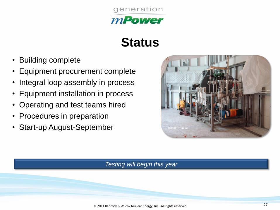
.27© 2011 Babcock & Wilcox Nuclear Energy, Inc. All rights reserved 27
Status
• Building complete
• Equipment procurement complete
• Integral loop assembly in process
• Equipment installation in process
• Operating and test teams hired
• Procedures in preparation
• Start-up August-September
Testing will begin this year
.28© 2011 Babcock & Wilcox Nuclear Energy, Inc. All rights reserved 28
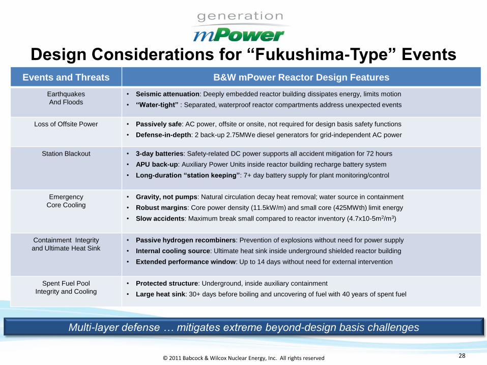
Design Considerations for “Fukushima-Type” Events
Events and Threats B&W mPower Reactor Design Features
Earthquakes
And Floods
• Seismic attenuation: Deeply embedded reactor building dissipates energy, limits motion
• “Water-tight” : Separated, waterproof reactor compartments address unexpected events
Loss of Offsite Power • Passively safe: AC power, offsite or onsite, not required for design basis safety functions
• Defense-in-depth: 2 back-up 2.75MWe diesel generators for grid-independent AC power
Station Blackout • 3-day batteries: Safety-related DC power supports all accident mitigation for 72 hours
• APU back-up: Auxiliary Power Units inside reactor building recharge battery system
• Long-duration “station keeping”: 7+ day battery supply for plant monitoring/control
Emergency
Core Cooling
• Gravity, not pumps: Natural circulation decay heat removal; water source in containment
• Robust margins: Core power density (11.5kW/m) and small core (425MWth) limit energy
• Slow accidents: Maximum break small compared to reactor inventory (4.7x10⁻⁵m2/m3)
Containment Integrity
and Ultimate Heat Sink
• Passive hydrogen recombiners: Prevention of explosions without need for power supply
• Internal cooling source: Ultimate heat sink inside underground shielded reactor building
• Extended performance window: Up to 14 days without need for external intervention
Spent Fuel Pool
Integrity and Cooling
• Protected structure: Underground, inside auxiliary containment
• Large heat sink: 30+ days before boiling and uncovering of fuel with 40 years of spent fuel
Multi-layer defense … mitigates extreme beyond-design basis challenges

.29© 2011 Babcock & Wilcox Nuclear Energy, Inc. All rights reserved 29
Lead Plant
• Generation mPower and TVA Letter of Intent
• Joint development and pursuit of construction permit and
operation license
• Up to six B&W mPower reactors at the Clinch River site
in Roane County, Tennessee
• Deploy first unit by 2020

.30© 2011 Babcock & Wilcox Nuclear Energy, Inc. All rights reserved 30
Integrated Part 50/52 Lead Plant Deployment ScheduleCY CY CY CY CY CY CY CY CY CY CY
2011 2012 2013 2014 2015 2016 2017 2018 2019 2020 2021
Clinch River Project – 10 CFR 50 Process
Submit CPA
NRC CPA Review
CP DSER
CP Issuance
Submit OL Application
NRC Review OL Application
FSER Issued
Fuel Load
COL Issuance
Submit DCA
NRC DCA Review
NRC COLA Review
DC RulemakingFSER IssuedCOLA Submittal
COD
mPower DCD & COLA – 10 CFR 52 Process
Pre-op TestingStart-up Testing
Site Prep/Construction/ITAAC/Fuel Load/Startup Testing
Hearing
COD
Site Prep/Construction
OL Issuance

.31© 2011 Babcock & Wilcox Nuclear Energy, Inc. All rights reserved 31
Conclusion
• B&W and Bechtel have formed an alliance to design and
construct turn-key mPower SMR plant
• The mPower modular reactor plant has a unique integral
reactor design with passive safety system design
• Design and licensing activities are well underway
• A comprehensive test program is in process
• A letter of intent has been signed with TVA for up to six units
for deployment of the first unit by 2020