introduction to autocad lar 543 spring 2008 · start > all programs > architecture and 3d...
TRANSCRIPT

1
Introduction to AutoCAD lar 543 spring 2008
Makie Suzuki, Chihiro Shinohara
in this session we cover:
- introduction
- basic operation
- basic drawing tools
- basic editing
In each section, important tools / commands are highlighted in red bold
for landscape architects
words in parenthesis are type-in commands
tutorials are formatted mainly for AudoCAD 2008 ver.

2
introductionWhat is CAD used for in practice?
construction document (C.D.)conceptual sketch (often used with other drawing media)
Overview of the Program
opening AutoCAD
tools
command line
Start > All Programs > Architecture and 3D Modeling > Autodesk > AutoCAD 2008 > AutoCAD 2008
Many tools will appear in Dashboard on the right side as default.
You can recover this palette from Tools > Dashboard or call back individual palettes by right-clicking on the menu bar (ACAD menu contains all tools that appear in the default palette)
Most frequently used tool palettes are:
Layer
Draw
Modify
You can directly type the tool name in as commands instead of clicking tool buttons. For the list of commands, see the booklet distributed in the class. This line will also show options within a tool. Please make a habit to constantly check the command line for what you can do with the tool you selected.
* In current setting at A-school, double clicking on a dwg fi le (dwg is an extention for AutoCAD) will open it in Microstation. Open the program fi rst, then File > Open > select your fi le.

3
basic operation
drawing units (units)
select / deselect
general shortcuts
layers
cursors
not in command in drawing command in modifying command
Settings and management
You can set the drawing units in Tools > Units. As a default, the measurements in the drawing is unitless. For example, when you draw a line with length “10”, AutoCAD doesn’t know if it is 10 miles or 10 millimeters until you set the unit. Remember to set it before you start drawing, or scale the drawn objects accordingly if you change the unit in the existing drawing.
Architectural (i.e. 1’-3 1/2”) and engineering (i.e. 1’-3.50”) units are most frequently used in the states. Please note that you have to specify the type of units in Insertion Scale tab when it is set to decimal, scientifi c, or fractional units.
For example, if you want to use millimeter:set “Type” in Length window to Decimal > set Insertion Scale to Millimeter
You can select the objects by clicking on an object or drawing a window around it. Drawing a window from left to right selects everything that the window crosses. Drawing a window from right to left selects everything that the window contains. You can deselect objects by doing the same operation while holding down Shift key, or deselect everything by hitting Esc key.
AutoCAD uses layer systems like Photoshop and SketchUp to organize a drawing.
Layer palette shows your current layer name and state. To access Layer Manager, click on the highlighted icon on the tool palette.
When you are not in command, the cursor looks like a cross with a square in the middle. When you are in drawing-related commands, the square disappear. When you are in modify-related commands, only the cross disappear. You can escape from a command by hitting Esc key.
Many general shortcuts are used in AutoCAD.
For example:Ctrl+S saves the dwg fi le (qsave)Ctrl+Z undoes the previous action (u) and Ctrl +Y redose the undone action again (redo)Ctrl+C copies and Ctrl+V pastesCtrl+P opens the plot window (plot)
4
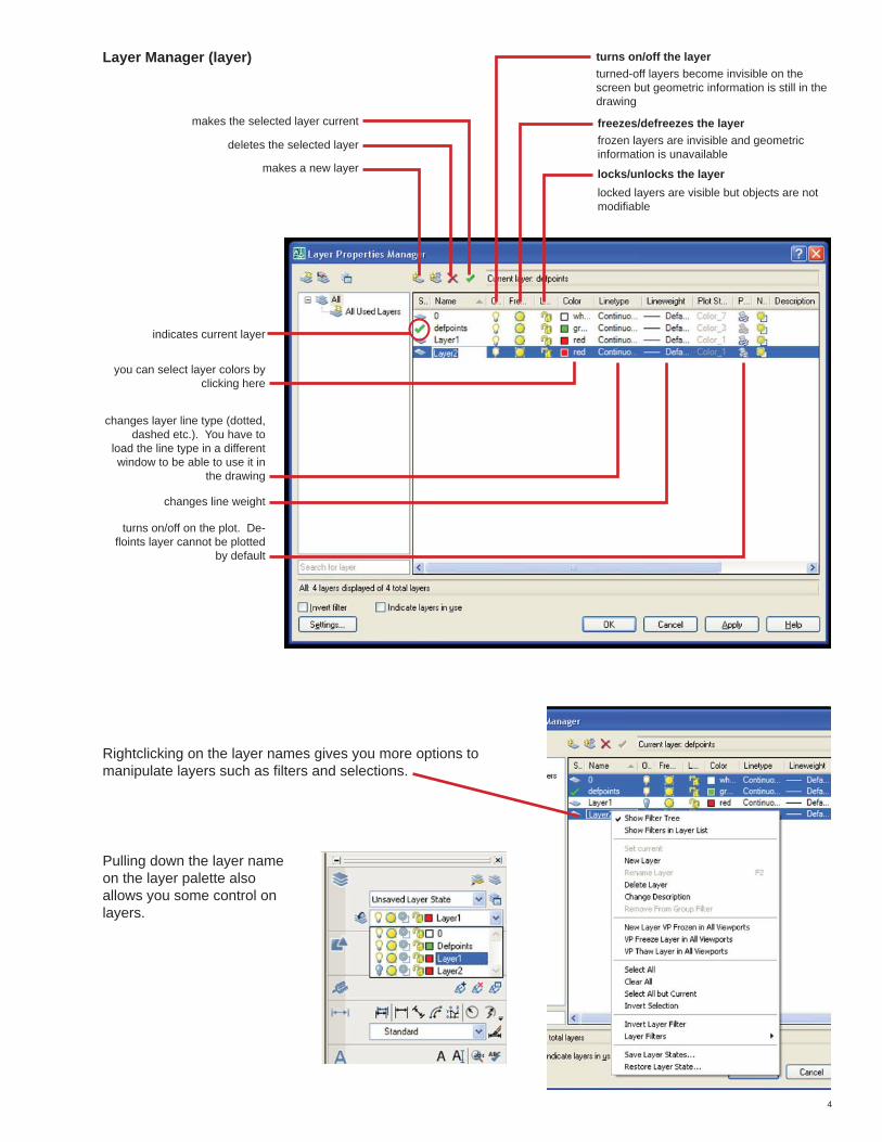
Layer Manager (layer)
indicates current layer
you can select layer colors by clicking here
changes layer line type (dotted, dashed etc.). You have to
load the line type in a different window to be able to use it in
the drawing
changes line weight
turns on/off on the plot. De-fl oints layer cannot be plotted
by default
makes a new layer
deletes the selected layer
makes the selected layer current
turns on/off the layerturned-off layers become invisible on the screen but geometric information is still in the drawing
freezes/defreezes the layerfrozen layers are invisible and geometric information is unavailable
locked layers are visible but objects are not modifi able
locks/unlocks the layer
Rightclicking on the layer names gives you more options to manipulate layers such as fi lters and selections.
Pulling down the layer name on the layer palette also allows you some control on layers.

5
zoom (z)
Tools
Zoom palette is accessible through right click on the menu bar > ACAD > Zoom.
You can also activate specifi c OSNAPs during drawing/inquiry operations by type-in. “End” for end-point, “mid” for middle point, “per” for perpendicular, “center” for center point, “tan” for tangent, etc.
There are settings that help you draw accurately. Please pay attention to the tabs below the command line and click on them to turn on/off.
To adjust settings, right click on any snap/tracking tabs. A setting window will pop up.
Some of the most common snaps/trackings are:
ORTHO (F8): restricts movements to horizontal and vertical directions.
GRID (F7): displays grids with the spacing that you specify.
POLAR (F10): tracks increments of the angle that you specify (i.e. if you set it to 30 degrees, it will track 30, 60, 90, 120 degrees etc.)
LWT: turns on/off the line width on display. Line width will appear uniform unless this icon is turned on (it does not affect the line widths on plot).
OSNAP (F3): snaps to existing objects on the screen. It also has a tool box that is ac-cessible through right click on the menu bar > ACAD > Object Snap.
SNAP (F9): snaps to increments of the spacing that you specify (i.e. if you set it to 2 in both x,y direction, it will snap on 2,2 : 2,4 : 10,8 etc.)
The middle wheel on your mouse allows you to easily zoom in and out.
Other useful zoom tools are:
zoom window (w) : allows you to draw a window around the area you want to zoom in.
zoom scale (sc) : allows you to zoom in/out in certain scale
zoom all (a) : allows you to zoom out to the entire drawing area
zoom extent (e) : allows you to zoom in/out to the area that you have any objects
snap & tracking

6
If you type “a” while drawing a polyline, your next segment will be an arc. It will continue to draw arc segments with tangent to the previous arc.
drawing tools
Drawing palette is accessible through the default dashbox or right click on the menu bar > ACAD > Draw.
LINE (l): draws a line from one point to another.
POLYLINE (pl): draws a line/curve with multiple control points.
Pay attention to the command line while using POLYLINE tool; it will show you variety of options for the next move you can take. Following are some of the examples.
drawing a polyline
hitting Esc
typing “cl”
If you hit “Esc” while drawing a polyline, the line terminates at the last point you clicked.
If you type “cl” while drawing a polyline, it draws a segment that connects the starting point and the last point you clicked (the line becomes a closed shape).
You can also draw an object with arcs using POLYLINE tool.
line
polyline

7
If you type “s” while drawing an arc segment, you can defi ne an arc angle by specifying three points that the arc goes through.
If you type “r” while drawing an arc segment, you can defi ne an arc radius.
RECTANGLE (rec): draws arectangle by defi ning two corners.
If you type “@” after defi ning the fi rst corner, you can specify the second corner by x,y coordination. For example, type @36,24 for 36” x 24” box.
If you type “d” after the fi rst corner, you can specify the second corner by the x and y distance from the fi rst corner. For example, type “d” > space > 36 > space > 24 for 36” x 24” box.
Click on the point where you want to place the fi rst corner of a rectangle or type in x,y coordination for precise imput.
POLYGON: draws a polygon by number of edges.
If you choose to inscribe in circle, it draws a polygon inside the circle with the radius you specify.
If you choose to circumscribe about circle, it draws a polygon that contains the circle with the radius you specify.
drawing tools (cont.)

8
CIRCLE (c): draws a circle.
SPLINE (spline): draws a spline connecting multiple points.
First click will defi ne center of the circle. defi ne the radius by typing it in or clicking.
Defi ne the points that a spline goes thgough by clicking.
End the tool by hitting Esc (terminates the spline at the last point clicked) or typing “cl” (adds a curve back to the starting point).
Spline has a tendency to increase the fi le size and may cause complecation when modify later. Excessive use of splines are not recommended especially when sharing a fi le with other people.
If you type “d” after the fi rst click, it will draw a circle with the diameter that you specify.
If you type “2p” or “3p” before clicking the center, it will draw a circle that goes through the points you specify.
drawing tools (cont.)
drawing tools not on the palette

9
modifying tools
Modifying palettes are accessible through the default dashbox or right click on the menu bar > ACAD > Modify.
COPY (cp): copies the selected objects from one place to another.
Select objects, click/type the base point and the second point that you want to copy objects to.
You can also copy+paste objects by selecting objects and right-clicking on them. It will save objects in clipboard and al-lows you to copy things from one fi le to another. Select “copy with basepoint” to copy things between fi les at precise loca-tions.
MIRROR (mi): mirrors objects along the line that you defi ne.
OFFSET(o): offsets objects to the distance you specify.
It will ask you whether you want to keep the original object or not after defi ning the mirror line. type “y” for yes or “n” for no.
It will ask you the distance to offset objects fi rst. you can specify it by typing the distance in or clicking two points on screen.
After entering the distance, grab an object to offset and click on the side that you want to offset it to.
You can offset an object multiple times in the same distance by repeating click.
ERASE (e): erases the selected objects. You can get the same effect by selecting objects and hitting Delete key.

10
modifying tools (cont.)
MOVE (m): moves the selected objects from one place to another.
SCALE (sc): scale objects by the ratio you specify.
you can also scale objects by the relative distances using “Reference” points.
select objects, click/type a base point, then type “r” for Reference.
click the base point again, then click the second point to defi ne the original distance. click the third point at where you wish the previous point to be after scaling objects.
In this way, it will scale the objects by the distance ratio of base point to the second point : base point to the third point. Position of the base point needs to be constant.
select objects, click/type a base point and click/type the scale numerically.
TRIM (tr): trim objects along specifi ed objects.
Create objects that you want to use as trim edges.
Click on Trim tool, select the trim edges and hit enter, click on the objects to trim on the side that you want to erase.
You can trim multiple objects at once by using selection window or “fence” tool.
To use selection window, draw a window after selecting trim edges instead of directly clicking on objects to trim.
To use fence, type “f” after selecting trim edges and draw a line. It will trim everything that the line crosses.
Select objects, click/type a base point and the second point that you want to move objects to.

11
EXTEND (ex): extend objects to reach specifi ed objects.
EXPLODE (x): break selected complex objects such as blocks and polylines down to lines and arcs.
polyline edit (pe) (pedit)
modifying tools (cont.)
Basic operation is similar to “trim”. Select objects that you want to use as extend edges and hit enter, click on the objects that you want to extend.
You can also extend multiple objects at once by using selection window or “fence” tool. For direc-tions, please see “trim” section.
There are extensive options to edit polyline. Options are available through Modify > Objects > Polyline.Pay close attention to the command line for the available options and directions.
Useful options are:
Close: adds a line to close an open polyline.
Join: joins touching multiple polylines into one objectAutoCAD does not join vertexes when overlapped. Make sure that the lines/arcs that you want to join are touch-ing at an exact point. If you are unsure, move one of the vertexes away and put it back together using “end point” snap.
Edit Vertex: modifi es control points.After you select Edit Vertex, a little X appears at the end of a polyline. It will move to the next control point every time you hit Enter. You should navigate this X to the con-trol point that you want to modify.
Adding a control point:Navigate X to the control point right before the segment that you waht to add a point. Type “i” to insert a vertex. click where you want to add a new point. Hit Esc to exit the option.
Dividing a polyline at a control point:Navigate X to the point that you want to divide. Type “b” for break. Type “g”. Hit Esc to exit the option.

12
Spline: makes a selected polyline into B-spline curve.
Decurve: makes a curved polyline into lines.
polyline edit (cont.)

13
How to create a CAD fi le from other digital fi les
in this session we cover: create a CAD fi le from
- ESRI GIS (version 9 or up)
- digitized drawings or image
From GIS
In ArcMap
Open Arc Toolbox
Select Export to CAD
Conversion Tool > To CAD > Export to CAD* When you can’t fi nd the tool you need, you can keyword search by clicking the search tab on the bottom of toolbox window. When you see the appropriate choice, you can either double click to open the tool or click “locate” to see where the tool is in the original view, “favorite” tab.
lar 543 spring 2008
Makie Suzuki, Chihiro Shinohara

14
Choose the layers that you want to export from the pull down bar on the top.
Select appropriate version of DWG
Specify the location and name of the fi le(may require you to type the extension “.dwg”
Press OK
REMEMBER, you normally have to rescale the drawing x12 because the unit of GIS data is usually in feet, but the default unit of CAD is usually in Inch.
Re-Scaling the drawing
(Scale) > (Select) >(All) > enter > specify appro-priate base point by clicking the point or typing the value such as (0,0) > (12) for scale factor.
Zoom extent to see the whole drawing.
* Show Help button offers brief explanations on the right.
Confi rm completion and open the exported dwg fi le in AutoCAD.
In AutoCAD

15
Create new layer “Image” in the layer manager and set the layer current or select existing layer, where you want to place the image.
Insert the drawingInsert < Raster Image Reference
Select the File
From Digitized Image
You can trace images in CAD to create new drawing of modify existing dwg fi les. You need a scaled drawing or an image, which include at least one object that you know the dimensions of.
From Scaled Drawing
“Image” window will pop up
Keep Insertion point “Specify on screen” Checked unless you know exact values of x and y coordinants.
Type appropriate value in Scalei.e. 1” = 10’ drawing in the dwg with “inch” unit set-ting - 120 (10 x 12)1” = 200’ drawing - 2400 (200 x 12)
Type value if you know or check the box if you want to control it once it appears in the model space.

16
If the image is over other lines that you want to see, adjust the order by
Select the image > Tool (on the top car) > Draw Order > Send to Back
You can adjust the brightness, contrast, and fade (transparency) of the image in the property.
Select the image > Right Click > Property
Align the Image to the existing object.
(Align) > select the image > click the fi rst point and specify destination > click the second point and specify the destination > for third point, normally just press enter > weather rescale the image or not should be decided by case by case.

17
From an image that the scale is unknown (but you know a dimention of object in the image)
When you insert the image, type approximate scale in the scale box or check “specify on scareen” box and adjust the image to convenient size on screen.
If you know one edge of the rectangle is 150”, draw a reference line of 150” along the edge.
Scale
(Scale) > select the image > specify the base point - one end of reference line would be easy > (r) for reference > click the one end of original edge > click the other end > click one end of reference line < click the other end
If necessary, align the image like in the p4