introduction - sorooh cables
TRANSCRIPT

Introduction
HTL Ltd., is erstwhile Government of India
Undertaking Company of HFCL Group, is
strategically in heart of Chennai, close to Airport
and has put up modern state of art Optical Fiber
Cable Manufacturing unit to cater to the growing
needs of Indian Digital Revolution. HFCL Group is
one of the largest infrastructure supplier of
Telecom operators in India and is engaged in
Manufacturing Optical Fiber
HTL is an ISO accredited Company with highly
sophisticated and automated, well equipped plant
to produce Duct/Micro Duct /Indoor/ Outdoor/
Wire Armoured/ CST Armoured / Aerial/ FTTH/
High fiber count Ribbon cables or any customized
cables to suit different client needs.
Its high-tech instrumentation for analysis and a rigorous
quality check ensures the highest industry standards. High
safety factor and narrow tolerance band guarantee the
production of 1,71,000 km of high precision optical fibre
cables in one single year. The company offers a complete
range of cables for telecommunications. Our products
meet all the international standards and specifications.
Supported by its own R&D facility, the company has
delivered custom-designed fibre optic cables with
superior performance in compliance as per ITU-T
Standards.
Cables are designed with high safety factor to ensure very
low strain i.e. 0.1% as against required level of 0.25% on
the optical fibre. It has High technology computerized
controlled machine with laser dia-measuring controllers,
lump detectors, tension measuring equipment ensures
self correcting measures at all stages of production to get
high performance close tolerance cable. Cable is designed
to meet IEC, EIA/TIA and Bellcore standards. The fibre
used in the cables meets relevant ITU-T specifications.
2

Multi - Tube Design Duct Cables
PRODUCT DESCRIPTION
Loose tube cables are the product of choice as the backbone in
Outside Plant (OSP) environments. The loose tube design
offers reliable transmission performance over a broad Rip Cord
Temperature range. Optical fibres and water-blocking
elements are placed inside buffer tubes. The core is
constructed by stranding the buffer tubes around FRP rod, the
central strength member. The core is wrapped with flexible
strength members covered with a water-blocking tape, then
encased with a black jacket. A rip cord is included under the
jacket for ease of entry.
APPLICATIONS
• Underground duct and lashed aerial
• Trunk, distribution and feeder cable
• Local loop, metro, long-haul and broadband network
FEATURES
Outer sheath
HDPE/LSZH Polyester Tape
FRP Rod
Flooding Jelly
Loose Tube with Fibres
Glass Yarn
SPECIFICATIONS
Fibre Count Available from 2F to 144F
Standards Compliance Telecordia GR-20, IEC 60794,
EIA/TIA, ITU-T, EN187000,
RUS1755.900
• Available with upto 144 Fibre
• Multiple Fibre types including hybrids
• Central strength members available in metallic or
dielectric
• Dry core standard (Optional)
• Standard tube size for all fibre counts
ADVANTAGES
• High Fibre density
• Multiple network applications
• Metallic option offers ease of location, dielectric design
eliminates grounding issues
ENVIRONMENTAL SPECIFICATIONS (TEMPERATURE)
Operation / Storage -40 to +70 Degree Celsius
Installation -30 to +75 Degree Celsius
• Reduces cable prep and installation time
• Reduces the number of tools required •
Speeds fibre access and cleanup
FIBRE
COUNT
DIAMETER WEIGHT
(mm) (Kg./Km)
Nominal Nominal
CRUSH TENSILE RESISTANCE
STRENGTH (N) (N/10cm)
Installation Operation
BENDING RADIUS (mm)
Temporary Permanent
2-24 10.0 80 2000 1000 2000 100 200
26-48 10.2 85 2000 1000 2000 102 204
50-72 10.5 90 2000 1000 2000 105 210
74-96 11.5 120 3000 1500 3000 115 230
98-120 13.0 155 3000 1500 3000 130 260
122-144 14.5 180 3000 1500 3000 145 290
The above shown cable designs are our standard designs, however, customised designs can also be offered on specific request. 3

Uni - Tube Design Duct Cables
PRODUCT DESCRIPTION
Single Loose tube cables offer a low cost alternative to
traditional stranded loose tube cables. The loose tube design
offers reliable transmission performance over a broad
temperature range. The rugged single loose tube design
features optical fibres placed inside a single gel-filled tube. The
core tube includes up to 24 distinctly colored fibers. The core
tube is then helically wrapped with water-blocking strength
members, then encased with a black jacket. A rip cord is
included under the jacket to provide ease of access to the core
tube.
APPLICATIONS
• Underground duct and lashed aerial
• Trunk, distribution and feeder cable
• Local loop, metro, long-haul and broadband network
FEATURES
Outer sheath -
HDPE/LSZH
Glass Yarn
Loose Tube with Fibres
Strength Member -
FRP Rod
Rip Cord
SPECIFICATIONS
Fibre Count Available from 2F to 24F
Standards Compliance Telecordia GR-20, IEC 60794,
EIA/TIA, ITU-T, EN187000,
RUS1755.900
• Available with upto 24 fibres
• Multiple Fibre types including hybrids
• Outer Strength members available in metallic or
dielectric
• Small Cable Diameter
ADVANTAGES
• High fibre density
• Multiple network applications
• Reduces cable preparation and installation time
ENVIRONMENTAL SPECIFICATIONS (TEMPERATURE)
Operation / Storage -40 to +70 Degree Celsius
Installation -30 to +75 Degree Celsius
• Reduces cost
• Installation of more fibres in less space
FIBRE
COUNT
DIAMETER WEIGHT (mm) (Kg./Km)
Nominal Nominal
CRUSH TENSILE
RESISTANCE STRENGTH (N)
(N/10cm) Installation Operation
BENDING RADIUS (mm)
Temporary Permanent
2-12 8.0 50 1000 800 2000 80 160
16-24 9.0 65 1000 800 2000 90 180
4 The above shown cable designs are our standard designs, however, customised designs can also be offered on specific request.

Multi - Tube Ribbon Design Duct Cables
PRODUCT DESCRIPTION
Stranded Tube Ribbon Cable is designed for Outside Plant
(OSP) applications, specifically lashed aerial and underground
duct installations. Our industry leading optical Fibre ribbons
are manufactured with high dimensional precision and low
planarity which equates to low losses during mass fusion
splicing. The stranded tube design features optical Fibres
ribbons placed inside gel-filled tubes. Each tube contains up to
12 discretely identified, 12-fibre ribbons for maximum design
load capacity of 576 optical fibres. The core is helically
wrapped with water-blocking strength members. Rip cords
are included under the inner sheath for ease of entry. A Nylon-
12 outer jacket protects the cable from rodent.
APPLICATIONS
• Underground duct and lashed aerial
• Trunk, distribution and feeder cable
• Local loop, metro, long-haul network
• Broadband network
Outer Jacket - Nylon
Inner Sheath -
HDPE/LSZH Central Strength Member (FRP)
Polyester Tape
Loose Tube with Ribbon
Rip Cord
SPECIFICATIONS
Fibre Count Available from 48F to 576F
Standards Compliance Telecordia GR-20, IEC 60794,
EIA/TIA, ITU-T, EN187000,
RUS1755.900
FEATURES
• Multiple Fibre types available
• Ribbon Fibre ENVIRONMENTAL SPECIFICATIONS (TEMPERATURE)
• Multiple stranded tubes Operation / Storage -40 to +70 Degree Celsius
Installation -30 to +60 Degree Celsius
ADVANTAGES
• High Fibre density • Compressive strength, rodent protection and ease of
• Multiple network applications location
• Individual Tube Access • Saves labour cost by offering mass fusion splicing
FIBRE
COUNT
DIAMETER WEIGHT
(mm) (Kg./Km)
Nominal Nominal
CRUSH TENSILE BENDING RADIUS
RESISTANCE STRENGTH (N) (mm)
(N/10cm) Installation Operation Temporary Permanent
48 19.0 280 7000 4000 2000 190 380
96 19.0 280 7000 4000 2000 190 380
144 20.5 340 8000 4500 2000 205 410
288 22.0 525 12000 6000 2000 220 440
576 30.0 740 12000 6000 2000 300 600
The above shown cable designs are our standard designs, however, customised designs can also be offered on specific request. 5

Uni - Tube Ribbon Design Duct Cables
PRODUCT DESCRIPTION
Unitube Ribbon Cable is designed for Outside Plant (OSP)
applications in underground duct installations. Our industry
leading optical Fibre ribbons are manufactured with high
dimensional precision and low planarity which equates to low
losses during mass fusion splicing. The Unitube design consists
of optical fibres ribbons placed inside a gel-filled tube. Each
tube contains up to 12 discretely identified, 12-Fibre ribbons
for maximum design load capacity of 144 optical fibres. Glass
yarn used provides the necessary tensile strength. Rip cords
are included under the outer sheath for ease of entry. Armoring
is provided for rodent protection. An outer HDPE sheath
embedded with FRP rods as additional strength members
completes the cable.
APPLICATIONS
• Underground duct and direct buried
• Trunk, distribution and feeder cable
• Local loop, metro, long-haul network
• Broadband network
Loose Tube with Ribbon
Outer Jacket HDPE/LSZH
ECCS Tape
Peripheral Strength Member (FRP)
Glass Yarn
Water Swellable Tape
SPECIFICATIONS
Fibre Count
Standards Compliance
Available from 24F to 144F
Telecordia GR-20, IEC 60794,
EIA/TIA, ITU-T, EN187000,
RUS1755.900
FEATURES
• Available with up to 144 Fibre
• Multiple Fibre types available
• Ribbon Fibre
ADVANTAGES
• High Fibre density
• Multiple network applications
ENVIRONMENTAL SPECIFICATIONS (TEMPERATURE)
Operation / Storage -40 to +70 Degree Celsius
Installation -30 to +60 Degree Celsius
• Saves labour cost by offering mass fusion splicing
• Compressive strength, rodent protection and ease of location
FIBRE
COUNT
DIAMETER WEIGHT
(mm) (Kg./Km)
Nominal Nominal
CRUSH TENSILE BENDING RADIUS
STRENGTH (N) RESISTANCE (mm) (N/10cm)
Installation Operation Temporary Permanent
24 11.5 125 2500 1800 2000 115 230
48 12.5 150 2500 1800 2000 125 250
96 13.0 160 2800 2000 2000 130 260
144 14.5 210 2800 2000 2000 145 290
6 The above shown cable designs are our standard designs, however, customised designs can also be offered on specific request.

Multi - Tube Ribbon Design Duct / Armoured Cables
PRODUCT DESCRIPTION
Stranded Tube Armored Ribbon Cable is designed for Outside
Plant (OSP) applications in underground duct or direct buried
installations. Our industry leading optical Fibre ribbons are
manufactured with high dimensional precision and low
planarity which equates to low losses during mass fusion
splicing. The stranded tube design features optical fibres
ribbons placed inside gel-filled tubes. Each tube contains up to
12 discretely identified, 12-fibre ribbons for maximum design
load capacity of 576 optical fibres. The core is helically
wrapped with water-blocking strength members. Rip cords
are included under the outer sheath for ease of entry.
Armoring below outer sheath provides rodent protection.
APPLICATIONS
• Underground duct and direct buried
• Trunk, distribution and feeder cable
• Local loop, metro, long-haul network
• Broadband network
Outer Jacket HDPE/LSZH
Loose Tube with Ribbon
Central Strength
Member (Steel Rod)
ECCS Tape
Glass Yarn
Ripcords
SPECIFICATIONS
Fibre Count Available from 48F to 576F
Standards Compliance Telecordia GR-20, IEC 60794,
EIA/TIA, ITU-T, EN187000,
RUS1755.900
FEATURES
• Available with upto 576 fibres
• Multiple Fibre types available ENVIRONMENTAL SPECIFICATIONS (TEMPERATURE)
• Ribbon Fibre Operation / Storage -40 to +70 Degree Celsius
• Multiple stranded tubes Installation -30 to +60 Degree Celsius
ADVANTAGES
• High Fibre density • Compressive strength, rodent protection and ease of
• Multiple network applications location
• Individual Tube Access • Saves labour cost by offering mass fusion splicing
FIBRE
COUNT
DIAMETER WEIGHT
(mm) (Kg./Km)
Nominal Nominal
TENSILE CRUSH RESISTANCE
STRENGTH (N) (N/10cm)
Installation Operation
BENDING RADIUS
(mm)
Temporary Permanent
48 16.0 250 3000 1000 2000 190 380
96 16.0 250 3000 1000 2000 190 380
144 18.0 300 3000 1000 2000 205 410
288 19.8 360 3000 1000 2000 198 396
576 22.0 480 4000 1000 2000 220 440
The above shown cable designs are our standard designs, however, customised designs can also be offered on specific request. 7

Multi - Tube Design Micro Duct Cables
PRODUCT DESCRIPTION
Loose Tube Micro duct cables are the product of choice as the
backbone in Outside Plant (OSP) environments. Its small outer
diameter and the required rigidity for blowing/pushing through
ducts offers lower minimum bending radius. The outer jacket
of Nylon-12 performs extremely low co-efficient of friction
while blowing through the micro ducts and also provides
termite resistance. Optical Fibres and water-blocking
elements are placed inside buffer tubes. The core is
constructed by stranding the buffer tubes around the FRP
central strength member. The core is wrapped with a water-
blocking tape, then encased with a Nylon-12 jacket. A rip cord is
included under the jacket for ease of entry.
APPLICATIONS
• Underground blowing/pushing in ducts
• Trunk, distribution and feeder cable
• Local loop, metro, long-haul network
• Broadband network
Outer Jacket -
Nylon/HDPE/LSZH
Water Blocking Tape
Rip Cord
FRP Rod
WS Yarn
Binder Yarn
Loose Tube with
Fibres
SPECIFICATIONS
Fibre Count Available from 2F to 144F
Standards Compliance Telecordia GR-20, IEC 60794,
EIA/TIA, ITU-T, EN187000,
RUS1755.900
FEATURES
• Multiple Fibre types available
• Multiple stranded tubes
• Dry Core Standard (Optional)
ADVANTAGES
• High fibre density in small outer diameter •
Multiple network applications
• Individual Tube Access
FIBRE DIAMETER WEIGHT
COUNT (mm) (Kg./Km)
Nominal Nominal
ENVIRONMENTAL SPECIFICATIONS (TEMPERATURE)
Operation / Storage -40 to +70 Degree Celsius
Installation -30 to +60 Degree Celsius
• Compressive strength, rodent protection and ease of
location
CRUSH TENSILE RESISTANCE BENDING RADIUS (mm)
STRENGTH (N) (N/10cm)
Installation Operation Temporary Permanent
2-48 6.0 25 500 200 500 60 120
50-72 7.2 35 1000 500 500 72 142
74-96 7.5 50 1000 500 500 75 150
98-144 9.2 70 1500 750 500 92 184
8 The above shown cable designs are our standard designs, however, customised designs can also be offered on specific request.

Uni - Tube Design Micro Duct Cables
SPECIFICATIONS
Fibre Count Available from 2F to 24
Standards Compliance Telecordia GR-20, IEC 60794,
EIA/TIA, ITU-T, EN187000,
RUS1755.900 Outer Sheath - Nylon-12
Aramid Yarn
Loose Tube
ENVIRONMENTAL SPECIFICATIONS (TEMPERATURE)
Operation / Storage -40 to +70 Degree Celsius
Installation -30 to +75 Degree Celsius
DIAMETER WEIGHT TENSILE
Optical Fibres
Rip Cord
CRUSH
FIBRE COUNT
(mm) (Kg./Km) STRENGTH (N)
Nominal NominalInstallation Operation
RESISTANCE BENDING RADIUS (mm) (N/10cm)
Temporary Permanent
2-12 3.8 11 800 400 1000 38 76
14-24 5.6 24 1000 500 1000 56 112
Uni - Tube Design (Mini)
SPECIFICATIONS
Fibre Count Available from 2F to 4F
Standards Compliance Telecordia GR-20, IEC 60794,
EIA/TIA, ITU-T, EN187000,
RUS1755.900
ENVIRONMENTAL SPECIFICATIONS (TEMPERATURE)
Operation / Storage -40 to +70 Degree Celsius
Installation -30 to +60 Degree Celsius
DIAMETER WEIGHT TENSILE
Outer Sheath Nylon - 12
Soft Inner Tube
Optical Fibres
Rip Cord
Aramid strength member
CRUSH
FIBRE COUNT
(mm) (Kg./Km) STRENGTH (N)
Nominal NominalInstallation Operation
RESISTANCE BENDING RADIUS (mm) (N/10cm)
Temporary Permanent
2 1.7 2.3 40 20 100 40 60
4 1.9 2.7 40 20 100 40 60
The above shown cable designs are our standard designs, however, customised designs can also be offered on specific request. 9

Multi Tube Design Indoor-Outdoor Cables
PRODUCT DESCRIPTION
Loose tube cables are the product of choice as the backbone in
Indoor/Outdoor environments. The rugged loose tube design
offers reliable transmission performance over a broad
temperature range. Optical Fibres are placed inside filled
buffer tubes containing gel. The core is constructed by
stranding the buffer tubes around a central strength member.
The core is wrapped with flexible strength members covered
with a water-blocking tape. Glass Yarns and an HDPE outer
jacket are applied. Rip cords are included under outer jacket
for ease of entry.
APPLICATIONS
• Underground duct, Aerial and Direct Burial •
Trunk, distribution and feeder cable
• Local loop, metro, long-haul and broadband network
FEATURES
• Available with upto 144 fibres
• Multiple Fibre types including hybrid
• Dry core standard (Optional)
• Uni-tube designs are also available upto 24 Fibres.
ADVANTAGES
• High fibre density
• Multiple network applications
• Dielectric design eliminates grounding issues
Rip Cord
Outer sheath
HDPE/LSZH Polyester Tape
FRP
Flooding Jelly
Loose Tube with Fibres
Glass Yarn Armouring
SPECIFICATIONS
Fibre Count Available from 2F to 144F
Standards Compliance Telecordia GR-20, IEC 60794,
EIA/TIA, ITU-T, EN187000,
RUS1755.900
ENVIRONMENTAL SPECIFICATIONS (TEMPERATURE)
Operation / Storage -40 to +70 Degree Celsius
Installation -30 to +75 Degree Celsius
• Reduces cable preparation and installation time •
Reduces the number of tools required
• Speeds fibre access and cleanup
FIBRE
COUNT
DIAMETER WEIGHT
(mm) (Kg./Km)
Nominal Nominal
CRUSH TENSILE
RESISTANCE STRENGTH (N)
(N/10cm) Installation Operation
BENDING RADIUS (mm)
Temporary Permanent
2-24 10.5 90 2000 1000 2000 105 210
26-48 10.8 92 2000 1000 2000 108 216
50-72 11.5 110 2000 1000 2000 115 230
74-96 14.5 175 4000 2000 2000 145 290
98-120 15.5 205 4000 2000 3000 155 310
122-144 17.0 255 4000 2000 3000 170 340
10 The above shown cable designs are our standard designs, however, customised designs can also be offered on specific request.

Uni - Tube Design Indoor-Outdoor Cables
PRODUCT DESCRIPTION
Single Loose tube cables offer a low cost alternative to
traditional stranded loose tube cables. The loose tube design
offers reliable transmission performance over a broad
temperature range. The rugged single loose tube design
features optical fibres placed inside a single gel-filled tube.
The core tube includes up to 24 distinctly colored fibers. The
core tube is then helically wrapped with water-blocking
strength members, then encased with an HDPE jacket.
APPLICATIONS
• Indoor and Outdoor
• Trunk, distribution and feeder cable
• Local loop, metro, long-haul and broadband network
FEATURES
• Multiple Fibre types including hybrids
• Small cable diameter
ADVANTAGES
• High fibre density
• Multiple network applications
• Reduces cable preparation and installation time
DIAMETER WEIGHT TENSILE
Outer sheath LSZH
Glass Yarn
Loose Tube with
Fibres
SPECIFICATIONS
Fibre Count Available from 2F to 24F
Standards Compliance Telecordia GR-20, IEC 60794,
EIA/TIA, ITU-T, EN187000,
RUS1755.900
ENVIRONMENTAL SPECIFICATIONS (TEMPERATURE)
Operation / Storage -20 to +60 Degree Celsius
Installation -15 to +65 Degree Celsius
• Reduces cost
• Installation of more fibres in less space
CRUSH
FIBRE COUNT
2-12
12-24
(mm) (Kg./Km) STRENGTH (N)
Nominal Nominal Installation Operation
9.0 62 2000 1000
10.0 80 2000 1000
RESISTANCE BENDING RADIUS (mm) (N/10cm)
Temporary Permanent
2000 90 180
2000 100 200
The above shown cable designs are our standard designs, however, customised designs can also be offered on specific request. 11

Multi - Tube Design Wire Armoured Cables
PRODUCT DESCRIPTION
Wire armoured cables are used in harsh environmental
conditions requiring greater tensile strength, higher crush and
impact resistance than standard steel tape armoured cables. Outer Sheath
The cable core consists of fiber filled buffer tubes stranded
around the central strength member. The core is water blocked
using suitable water blocking elements . An inner sheath is
provided over the core and galvanised steel wire armouring is
provided over it. An outer HDPE sheath is extruded over this
armouring.
APPLICATIONS
• Suitable for duct or buried installations such as tunnels. •
Excellent mechanical features.
• High anti-rodent protection.
HDPE/LSZH
Steel Wires
Inner Sheath HDPE
FRP Rod
Polyester Tape
Loose Tube with Fibres
SPECIFICATIONS
Fibre Count Available from 2F to 144F
Standards Compliance Telecordia GR-20, IEC 60794,
EIA/TIA, ITU-T, EN187000,
RUS1755.900
FEATURES
• Multiple Fibre types available
• Galvanised Steel Wire Armouring ENVIRONMENTAL SPECIFICATIONS (TEMPERATURE)
• High strength Operation / Storage -40 to +70 Degree Celsius
• High crush & impact resistance Installation -30 to +60 Degree Celsius
ADVANTAGES
• High Fibre density • Improves Compressive strength and rodent protection
• Multiple network applications
FIBRE
COUNT
2-12
DIAMETER WEIGHT
(mm) (Kg./Km)
Nominal Nominal
14.5 295
CRUSH TENSILE
RESISTANCE STRENGTH (N)
(N/10cm) Installation Operation
19000 10000 4000
BENDING RADIUS (mm)
Temporary Permanent
145 290
12-24 14.5 295 19000 10000 4000 145 290
26-36 14.5 295 19000 10000 4000 145 290
38-48 16.0 350 22000 12000 4000 160 320
50-72 16.0 350 22000 12000 4000 160 320
74-96 17.5 415 23000 13000 4000 175 350
98-144 20.5 560 25000 14000 4000 205 410
12 The above shown cable designs are our standard designs, however, customised designs can also be offered on specific request.

Multi - Tube Single Sheath Design CST Armoured Cables
PRODUCT DESCRIPTION
Loose tube cables are the product of choice as the backbone in
Outside Plant (OSP) environments. The rugged loose tube
design offers reliable transmission performance over a broad
temperature range. Optical fibres and water-blocking
elements are placed inside buffer tubes. The core is
constructed by stranding the buffer tubes around a central
strength member. The core is wrapped with flexible strength
members covered with a polyester tape. A corrugated steel
armor is applied and then encased with a black jacket. Rip
cords are included under the armor for ease of entry.
APPLICATIONS
• Direct buried, underground duct
Outer sheath
HDPE/LSZH
Polyester Tape
Glass Yarn
FRP Rod
Corrugated Steel Tape
Loose Tube with Fibres
Rip Cord
SPECIFICATIONS
Fibre Count Available from 2F to 144F
• Trunk, distribution and feeder cable
• Local loop, metro, long-haul and broadband network
FEATURES
• Multiple Fibre types including hybrid
• Dry core standard (Optional)
• Corrugated Steel Armour
ADVANTAGES
• High Fibre density
• Multiple network applications
• Reduces cable preparation and installation time
DIAMETER WEIGHT TENSILE
Standards Compliance Telecordia GR-20, IEC 60794,
EIA/TIA, ITU-T, EN187000,
RUS1755.900
ENVIRONMENTAL SPECIFICATIONS (TEMPERATURE)
Operation / Storage -40 to +70 Degree Celsius
Installation -30 to +75 Degree Celsius
• Reduces the number of tools required
• Improves compressive strength and rodent protection
CRUSH
FIBRE COUNT
(mm) (Kg./Km) STRENGTH (N) Nominal Nominal
Installation Operation
RESISTANCE BENDING RADIUS (mm) (N/10cm)
Temporary Permanent
2-24 11.5 130 4000 2000 4000 115 230
26-48 11.8 135 4000 2000 4000 118 236
50-72 12.5 160 4000 2000 4000 125 250
74-96 13.8 185 5000 2500 4000 138 276
98-120 15.5 235 5000 2500 4000 155 310
122-144 16.5 270 5000 2500 4000 165 330
The above shown cable designs are our standard designs, however, customised designs can also be offered on specific request. 13

Multi - Tube Double Sheath Design CST Armoured Cables
PRODUCT DESCRIPTION
Loose tube cables are the product of choice as the backbone in
Outside Plant (OSP) environments. The rugged loose tube
design offers reliable transmission performance over a broad
temperature range. Optical fibres and water-blocking elements
are placed inside buffer tubes. The core is constructed by
stranding the buffer tubes around a central member. The core is
wrapped with flexible strength members covered with a
polyester tape then encased with a black inner jacket. A
corrugated steel armor is applied and a black outer jacket
completes the cable construction. Rip cords are included under the
inner jacket and armor for ease of entry.
APPLICATIONS
• Direct bury, underground duct and lashed aerial
• Trunk, distribution and feeder cable
• Local loop, metro, long-haul and broadband network
FEATURES
• Multiple fibre types including hybrid
• Dry core standard (Optional)
• Corrugated Steel Armour
ADVANTAGES
• High Fibre density
• Multiple network applications
• Reduces cable preparation and installation time
Outer sheath
HDPE/LSZH
Corrugated Steel Tape
Inner Sheath PE
FRP Rod
Polyester Tape
Loose Tube with Fibres
Rip Cord
SPECIFICATIONS
Fibre Count Available from 2F to 144F
Standards Compliance Telecordia GR-20, IEC 60794,
EIA/TIA, ITU-T, EN187000,
RUS1755.900
ENVIRONMENTAL SPECIFICATIONS (TEMPERATURE)
Operation / Storage -40 to +70 Degree Celsius
Installation -30 to +75 Degree Celsius
• Improves compressive strength and rodent protection •
Speeds fibre access and cleanup
FIBRE
COUNT
DIAMETER WEIGHT
(mm) (Kg./Km)Nominal Nominal
CRUSH TENSILE
RESISTANCE STRENGTH (N)
(N/10cm) Installation Operation
BENDING RADIUS (mm)
Temporary Permanent
2-24 13.8 170 2670 1500 4000 138 276
26-48 14.5 195 2670 1500 4000 145 290
50-72 15.0 200 2670 1500 4000 150 300
74-96 16.0 240 3000 2000 4000 160 320
98-120 17.5 285 3000 2000 4000 175 350
122-144 18.5 320 3000 2000 4000 185 370
14 The above shown cable designs are our standard designs, however, customised designs can also be offered on specific request.

Uni- Tube Design CST Armoured Cables
PRODUCT DESCRIPTION
Single Loose tube cables offer a low cost alternative to
traditional stranded loose tube cables. Armored cables are
designed for improved mechanical and rodent protection in
direct buried applications. The loose tube design offers Outer sheath
reliable transmission performance over a broad temperature
range. The rugged single loose tube design features optical
fibres placed inside a single gel-filled tube. The core tube
includes up to 24 distinctly colored fibers. The core is
wrapped with flexible strength members and covered with a
water-blocking tape. A corrugated steel armor is applied and
then encased with a black jacket. Rip cords are included
under the armor for ease of access to the core tube.
HDPE/LSZH Corrugated Steel Tape
W S Tape
Fibre Bundles in tube
Rip Cord
Glass Yarn
SPECIFICATIONS
Fibre Count Available from 2F to 24F
APPLICATIONS
• Direct buried and underground duct
• Trunk, distribution and feeder cable
• Local loop, metro, long-haul and broadband network
FEATURES
• Multiple Fibre types
• Corrugated Steel Armour
• Highly flexible
ADVANTAGES
• Multiple network applications
• Reduces cable preparation and installation time •
Easy Handling
DIAMETER WEIGHT TENSILE
Standards Compliance Telecordia GR-20, IEC 60794,
EIA/TIA, ITU-T, EN187000,
RUS1755.900
ENVIRONMENTAL SPECIFICATIONS (TEMPERATURE)
Operation / Storage -40 to +70 Degree Celsius
Installation -30 to +75 Degree Celsius
• Reduces cost
• Improves compressive strength and rodent protection
CRUSH
FIBRE COUNT
6
12
24
(mm) (Kg./Km) STRENGTH (N)
Nominal Nominal Installation Operation
8.8 90 1500 750
8.8 90 1500 750
10.5 100 1500 750
RESISTANCE BENDING RADIUS (mm) (N/10cm)
Temporary Permanent
4000 88 176
4000 88 176
4000 105 210
The above shown cable designs are our standard designs, however, customised designs can also be offered on specific request. 15

Multi - Tube ADSS Double Sheath Design Aerial Cables
PRODUCT DESCRIPTION
ADSS (All Dielectric Self Supporting) cables are designed for
installation on poles in distribution and transmission
environment mainly where live wire installation is required.
Optical fibres inside gel filled tubes are stranded around a
central strength member. The core is water blocked by use of
suitable water blocking elements. Inner PE sheath is provided
over which a layer of Aramid yarn is uniformly distributed that
provides the necessary tensile strength. The outer sheath is
then extruded over this core. Ripcords facilitate access to the
cable core. ADSS cables are suitable for use in harsh
environment. These cables are designed based on the required
span length and the prevailing environmental conditions.
APPLICATIONS
Rip Cord
Outer sheath - HDPE
Inner Sheath - PE
Polyester Tape
FRP Rod
Loose Tube with
Fibres Flooding Jelly
Aramid Yarn
SPECIFICATIONS
Fibre Count Available from 2F to 144F
• Aerial, Underground duct and Direct Burial
• Trunk, distribution and feeder cable
• Power utilities
Standards Compliance Telecordia GR-20, IEC 60794,
EIA/TIA, ITU-T, EN187000,
RUS1755.900, IEEE.P-1222
FEATURES
• Anti-tracking resistance
• Multiple fiber types including Hybrids
• Self supporting
• Unitube designs available
ADVANTAGES
• Live power line installation
• Multiple network applications
• Dielectric design eliminates grounding issues
• Increase in lifetime die to anti-tracking property
DIAMETER WEIGHT TENSILE
ENVIRONMENTAL SPECIFICATIONS (TEMPERATURE)
Operation / Storage -40 to +70 Degree Celsius
Installation -30 to +75 Degree Celsius
• Reduces number of tools required due to absence of
messenger
Note: Custom designs for various span lengths available
upon request.
CRUSH
FIBRE COUNT
(mm) (Kg./Km) STRENGTH (N)
Nominal NominalInstallation Operation
RESISTANCE BENDING RADIUS (mm) (N/10cm)
Temporary Permanent
2-24 13.5 140 4000 2500 2000 135 270
26-48 13.5 140 4000 2500 2000 135 270
50-72 14.5 160 5000 3000 2000 145 290
74-96 15.5 180 6000 4000 2000 155 310
98-120 17.0 220 6000 4000 2000 170 340
122-144 18.5 260 6000 4000 2000 185 370
16 The above shown cable designs are our standard designs, however, customised designs can also be offered on specific request.

Multi - Tube ADSS Single Sheath Design Aerial Cables
PRODUCT DESCRIPTION
ADSS (All Dielectric Self Supporting) cables are designed for
installation on poles in distribution and transmission
environment mainly where live wire installation is required.
Optical fibres inside gel filled tubes are stranded around a
central strength member. The core is water blocked by use of
suitable water blocking elements. A layer of Aramid yarn
uniformly distributed provides the necessary tensile strength.
The outer sheath is extruded over this core. Ripcords facilitate
access to the cable core. ADSS cables are suitable for use in
harsh environment. These cables are designed based on the
required span length and the prevailing environmental
conditions.
APPLICATIONS
• Aerial , Underground duct and Direct Burial •
Trunk, distribution and feeder cable
• Local loop, metro, long-haul and broadband network
FEATURES
• Available with upto 144 fibres
• Multiple Fibre types including hybrids
• Dry core standard (Optional)
• Uni-tube designs are also available upto 24 Fibres
ADVANTAGES
• High fibre density
• Multiple network applications
• Dielectric design eliminates grounding issues
DIAMETER WEIGHT TENSILE
Rip Cord
Outer sheath HDPE
FRP Rod
Water Blocking Tape
Loose Tube with Fibres
Aramid Yarn
SPECIFICATIONS
Fibre Count Available from 2F to 144F
Standards Compliance Telecordia GR-20, IEC 60794,
EIA/TIA, ITU-T, EN187000,
RUS1755.900
ENVIRONMENTAL SPECIFICATIONS (TEMPERATURE)
Operation / Storage -40 to +70 Degree Celsius
Installation -30 to +75 Degree Celsius
• Reduces cable preparation and installation time •
Reduces the number of tools required
• Speeds fibre access and cleanup
CRUSH
FIBRE COUNT
(mm) (Kg./Km) STRENGTH (N)
Nominal NominalInstallation Operation
RESISTANCE BENDING RADIUS (mm) (N/10cm)
Temporary Permanent
2-24 11.5 120 3000 1500 2000 115 230
26-48 11.5 130 3000 1500 2000 115 230
50-72 12.5 150 3000 1500 2000 125 250
74-96 13.5 180 4000 2000 2000 135 270
98-144 16.5 195 4000 2000 2000 165 330
The above shown cable designs are our standard designs, however, customised designs can also be offered on specific request. 17

Uni - Tube Figure-8 Design Aerial Cables
PRODUCT DESCRIPTION
Figure of 8 self support cables are design for use in aerial
applications as an alternative to lashing. An integrated
messenger wire support provides the necessary tensile strength
and outer HDPE jacket is provided in the form of figure of 8.
APPLICATIONS
• Aerial self support medium span installations •
Trunk, distribution and feeder cable
• Local loop, metro, long-haul and broadband network
FEATURES
• Multiple Fibre types
• Confirms to standard pole attachment hardware •
Small diameter and light weight
ADVANTAGES
• Light weight and compact
• Multiple network applications
FIBRE DIAMETER WEIGHT TENSILE
Messenger Wire
Web
Outer Jacket– HDPE
Loose Tube with Fibres
SPECIFICATIONS
Fibre Count Available from 2F to 24F
Standards Compliance Telecordia GR-20, IEC 60794,
EIA/TIA, ITU-T, EN187000,
RUS1755.900
ENVIRONMENTAL SPECIFICATIONS (TEMPERATURE)
Operation / Storage -40 to +70 Degree Celsius
Installation -30 to +75 Degree Celsius
• Standard installation practices
CRUSH
RESISTANCE BENDING RADIUS (mm) COUNT (mm)
Nominal
2-24 6.5 X 11.0
(Kg./Km) STRENGTH (N) Nominal
Installation Operation
65 2000 1000
(N/10cm)
Temporary Permanent
2000 500 110
18 The above shown cable designs are our standard designs, however, customised designs can also be offered on specific request.

Multi - Tube Figure-8 Design Aerial Cables
PRODUCT DESCRIPTION
Figure of 8 cable design offers an alternative for aerial cable
installations in stringent environmental conditions. The optical
fibers are placed inside gel-filled buffer tubes. The core is
constructed by stranding the buffer tubes around a central
strength member and covered with suitable water blocking
elements and then sheathed with an outer jacket and an
integrated steel messenger. A rip cord is provided for easy
access to the cable core. A stranded messenger wire is sheathed
along with the core in the form of figure of 8.
APPLICATIONS
• Aerial self support
• Trunk, distribution and feeder cable
• Local loop, metro, long-haul and broadband network
FEATURES
Messenger Wires
Web
Outer Jacket -HDPE
Rip Cord
Loose Tube with Fibres
FRP Rod
Water SwellableTape
SPECIFICATIONS
Fibre Count
Standards Compliance
Available from 2F to 144F
Telecordia GR-20, IEC 60794,
EIA/TIA, ITU-T, EN187000,
RUS1755.900
• Available upto 144 fibres
• Multiple Fibre types including hybrids
• Wet core (Optional)
• Confirms to standard pole attachment hardware
• Uni-tube designs are also available upto 24Fibres.
ADVANTAGES
• High fibre density
• Multiple network applications
• Reduces cable preparation and installation time
DIAMETER WEIGHT TENSILE
ENVIRONMENTAL SPECIFICATIONS (TEMPERATURE)
Operation / Storage -40 to +70 Degree Celsius
Installation -30 to +75 Degree Celsius
• Reduces the number of tools required
• Speeds fibre access and cleanup
• Standard installation practices
CRUSH
FIBRE COUNT
2-24
26-48
50-72
74-96
98-120
122-144
(mm) (Kg./Km)
Nominal Nominal
10.0 X 17.0 130
10.0 X 17.0 130
11.0 X 17.5 145
12.2 X 18.5 175
14.0 X 20.5 200
15.5 X 22.0 230
RESISTANCE STRENGTH (N)
(N/10cm) Installation Operation
5000 2500 2000
5000 2500 2000
6000 3000 2000
6000 3000 2000
6000 3000 2000
6000 3000 2000
BENDING RADIUS (mm)
Temporary Permanent
100 200
100 200
110 220
122 244
140 280
155 310
The above shown cable designs are our standard designs, however, customised designs can also be offered on specific request. 19

Flat Type Drop Cable FTTH Cables
PRODUCT DESCRIPTION
HTL offers the most complete solution for the FTTH
application. The Flat Type Drop Cable is designed for use in
Aerial and duct/conduit environments. The single tube
contains gel which provides ease of clean up. Dielectric
strength members (FRP/ARP) placed parallel to single loose
tube, one on each side, to provide necessary longitudinal
strength.
This product is available with G657A optical Fibre also and
provides increased bend performance.
APPLICATIONS
• FTTH Aerial and Duct/Conduit
• Local loop, Broadband network
FEATURES
• Available with upto 12 fibres
• Multiple Fibre types including bend resistant
Outer Sheath -
HDPE/LSZH
SPECIFICATIONS
Fibre Count
Standards Compliance
Loose Tube FRP / ARP
with Fibres Rod
Available from 2F to 12F
Telecordia GR-20, IEC 60794,
EIA/TIA, ITU-T, EN187000,
RUS1755.900
• Strength members available in metallic also
ADVANTAGES
• Easy Drop
• Multiple network applications
• Reduces cable preparation and installation time
DIAMETER WEIGHT TENSILE
ENVIRONMENTAL SPECIFICATIONS (TEMPERATURE)
Operation / Storage -40 to +70 Degree Celsius
Installation -10 to +70 Degree Celsius
• Reduces cost
• Easy Installation
CRUSH
FIBRE COUNT
2-12
(mm) (Kg./Km)
Nominal Nominal
7.2 x 3.5 60
RESISTANCE STRENGTH (N)
(N/10cm) Installation Operation
1200 600 2000
BENDING RADIUS (mm)
Temporary Permanent
100 200
20 The above shown cable designs are our standard designs, however, customised designs can also be offered on specific request.

High Bend Flexi Drop Cable FTTH Cables
PRODUCT DESCRIPTION
The high bend flexi drop cable is designed for use in aerial and
duct/conduit environments. The optical fibers are embedded in
the sheath. Dielectric strength members (FRP/ARP rods) placed
parallel to optical fibres provide the necessary longitudinal
strength.
Outer Sheath - Optical FRP / ARP Rod
HDPE/LSZH Fibres
APPLICATIONS SPECIFICATIONS
• FTTH Aerial and Duct/Conduit
• Local loop
• Broadband network
FEATURES
• Available upto 4 fibres
• Multiple Fibre types including bend resistant G 657A •
Metallic strength members also available
ADVANTAGES
• Easy Drop
• Multiple network applications
• Reduces cable preparation and installation time
Fibre Count Available from 2F to 4F
Standards Compliance Telecordia GR-20, IEC 60794,
EIA/TIA, ITU-T, EN187000,
RUS1755.900
ENVIRONMENTAL SPECIFICATIONS (TEMPERATURE)
Operation / Storage -40 to +70 Degree Celsius
Installation -10 to +70 Degree Celsius
• Reduces cost
• Easy installation
FIBRE
COUNT
DIAMETER WEIGHT
(mm) (Kg./Km)
Nominal Nominal
TENSILE CRUSH RESISTANCE
STRENGTH (N) (N/10cm)
Installation Operation
BENDING RADIUS (mm)
Temporary Permanent
2 2.0 x 3.1 10 200 100 500 30 60
4 2.2 x 3.5 11 200 100 500 30 60
The above shown cable designs are our standard designs, however, customised designs can also be offered on specific request. 21

Figure-8 Type Drop Cables FTTH Cables
PRODUCT DESCRIPTION
The Flat type Figure of 8 Drop cable is designed for use in aerial
applications. The optical fibers are placed inside a single gel-
filled tube and sheathed with an outer jacket in figure of 8
o
form. Dielectric strength members (FRP/ARP rod) placed 180
apart, provide the necessary longitudinal strength and a steel
wire/FRP rod as messenger also serves as an additional
strength member.
Outer Sheath - Optical FRP /* FRP Rod /
HDPE/LSZH Fibres ARP Rod Steel Wire
APPLICATIONS SPECIFICATIONS
• FTTX
• Aerial
• Local loop
• Broadband network
FEATURES
• Multiple Fibre types including bend resistant
• Strength members available in metallic also
ADVANTAGES
• Easy Drop
• Multiple network applications
• Reduces cable preparation and installation time
DIAMETER WEIGHT TENSILE
Fibre Count Available from 2F to 12F
Standards Compliance Telecordia GR-20, IEC 60794,
EIA/TIA, ITU-T, EN187000,
RUS1755.900
ENVIRONMENTAL SPECIFICATIONS (TEMPERATURE)
Operation / Storage -30 to +70 Degree Celsius
Installation -25 to +75 Degree Celsius
• Reduces cost
• Easy Installation
CRUSH
FIBRE COUNT
2-6
8-12
(mm) (Kg./Km)
Nominal Nominal
6.8 x 3.0 23
7.0 x 3.0 25
RESISTANCE STRENGTH (N)
(N/10cm) Installation Operation
1200 600 1000
1200 600 1000
BENDING RADIUS (mm)
Temporary Permanent
60 120
60 120
22 The above shown cable designs are our standard designs, however, customised designs can also be offered on specific request.

Distribution Cables Indoor Cables
PRODUCT DESCRIPTION
Tight buffered cables are designed perfectly for inter-
equipment connections in indoor applications. These cables
have high strength and good bend performance. Individual
fibers are tight buffered with Nylon-12/PVC up to 900 microns
which are surrounded with Aramid Yarn and overall jacketed
with LSZH/PVC compound. The tight buffered construction is
ideal for direct termination of connectors consequently saving on
installation time.
APPLICATIONS
• Indoor, Ducts/Conduits
• Local loop, Broadband network
FEATURES
Outer sheath
LSZH/PVC
Aramid Yarn
Tight Buffered Fibres
SPECIFICATIONS
Fibre Count
Standards Compliance
Available from 2F to 24F
Telecordia GR-20, IEC 60794,
EIA/TIA, ITU-T, EN187000,
RUS1755.900
• Multiple Fibre types
• Outer jacket PVC (Optional)
ENVIRONMENTAL SPECIFICATIONS (TEMPERATURE)
Operation / Storage -30 to +70 Degree Celsius
Installation -25 to +75 Degree Celsius
ADVANTAGES
• Good bending performance • Facilitates flexible installations
• High tensile strength, tight structure, light weight • Easy to operate and splice.
• Small Dimension
FIBRE
COUNT
DIAMETER WEIGHT
(mm) (Kg./Km)
Nominal Nominal
TENSILE CRUSH RESISTANCE
STRENGTH (N) (N/10cm)
Installation Operation
BENDING RADIUS (mm)
Temporary Permanent
1-4 5.0 26 1000 500 500 50 100
6-8 5.8 32 1000 500 500 58 116
10-12 6.2 36 1000 500 500 62 124
14-16 7.5 52 1200 600 500 75 150
18-24 8.0 60 1200 600 500 80 160
The above shown cable designs are our standard designs, however, customised designs can also be offered on specific request. 23

Simplex/Duplex Cables Indoor Cables
PRODUCT DESCRIPTION Outer sheath
HTL’s Simplex/Duplex cables are designed to withstand all
the requirements in a premise environment. Simplex cable
consists of a single Nylon/ PVC tight buffered fiber surrounded
by Aramid Yarn and jacketed with LSZH/ PVC. Duplex cable is
like two simplex cables jointed by a thin web. Simplex cables
are used for one way data transfer while duplex / zipcord
enables bidirectional data transfer. The tight buffered
construction is ideal for direct termination of connectors thus
saving on installation time.
SPECIFICATIONS
Fibre Count Available in 1F & 2F
Standards Compliance Telecordia GR-20, IEC 60794,
EIA/TIA, ITU-T, EN187000,
RUS1755.900
ENVIRONMENTAL SPECIFICATIONS (TEMPERATURE)
Operation / Storage -30 to +70 Degree Celsius
Installation -25 to +75 Degree Celsius
DIAMETER WEIGHT TENSILE
LSZH/PVC
Tight Buffered Fibre
Aramid Yarn
Tight Buffered Fibre
Outer sheath
LSZH/PVC
Aramid Yarn
CRUSH
FIBRE COUNT
(mm) (Kg./Km) STRENGTH (N)
Nominal NominalInstallation Operation
RESISTANCE BENDING RADIUS (mm) (N/10cm)
Temporary Permanent
Simplex
Duplex Maxizip)
Simplex
Duplex Minizip)
3.0 8 300
6.0 16 600
2.0 4 200
4.0 8 400
150 500 30 60
300 500 30 60
100 500 30 60
200 500 30 60
24 The above shown cable designs are our standard designs, however, customised designs can also be offered on specific request.

Breakout Cables Indoor Cables
PRODUCT DESCRIPTION
The optical fibre breakout Cable is designed considering Central
office (CO) connectivity. The cable consists of interconnect
cable subunits surrounding a central strength element. The
subunits are surrounded by strength members and a common
flame retardant PVC jacket. Each subunit is ideally suited to be Outer sheath -LSZH
attached to small form factor connectors. Tight Buffered Fibre
Polyester Tape
FRP
Simplex Cables
E-Glass Yarn
Aramid Yarn
APPLICATIONS SPECIFICATIONS
• Indoor; Riser, Plenum Fibre Count Available from 1F to 6F
• Ducts/Conduits Standards Compliance Telecordia GR-20, IEC 60794,
• Local loop EIA/TIA, ITU-T, EN187000,
• Broadband network RUS1755.900
FEATURES
• Individual fiber unit accessible
• Designed for convenient installation of optical
connectors
ADVANTAGES
• High tensile strength and light weight
• Facilitates flexible installations
• Easy to operate and splice
DIAMETER WEIGHT TENSILE
ENVIRONMENTAL SPECIFICATIONS (TEMPERATURE)
Operation / Storage -30 to +70 Degree Celsius
Installation -25 to +75 Degree Celsius
• Compatible with standard central office equipment.
CRUSH
FIBRE COUNT
(mm) (Kg./Km) STRENGTH (N)
Nominal Nominal Installation Operation
RESISTANCE BENDING RADIUS (mm) (N/10cm)
Temporary Permanent
1-4 7.5 55 600 300 500 75 150
6 8.5 72 600 300 500 85 160
The above shown cable designs are our standard designs, however, customised designs can also be offered on specific request. 25

Ribbon Interconnect Cable Indoor Cables
PRODUCT DESCRIPTION
The optical fibre ribbon interconnect cable is designed to be
attached directly to 12-fibre array connectors, like MPO or MTP.
Use it with array connectors on either side for a ribbon jumper
cable, or as a transition cable with the array connector on one side
and a high fibre count cable on the other. The cable consists single
ribbon of 8/12 fibres surrounded by aramid yarns and provided
with an outer PVC jacket which is flame retardant
APPLICATIONS
Flame Retardant
PVC Jacket
Ribbon Resin
Optical Fiber
Dielectric Aramid
Strength Members
SPECIFICATIONS
• MPO/MTP 12 fibre array connectors Fibre Count 12F
Standards Compliance ANSI /ICEA S-83-596, GR-
409-CORE
FEATURES
• Multiple fibre types available
• Riser rated design
ENVIRONMENTAL SPECIFICATIONS (TEMPERATURE)
Operation / Storage -40 to +70 Degree Celsius
Installation -30 to +60 Degree Celsius
ADVANTAGES
• Trouble free installation
• To be directly attached to MTO/MTP 12 fibre array connectors
• Fire rated cable
FIBRE
COUNT
DIAMETER WEIGHT
(mm) (Kg./Km)
Nominal Nominal
TENSILE BENDING RADIUS
STRENGTH (N) (mm)
Installation Temporary Permanent
12 4.2 x 2.2 10.0 200 100 25 50
26 The above shown cable designs are our standard designs, however, customised designs can also be offered on specific request.
Strength Member - FRP Rods
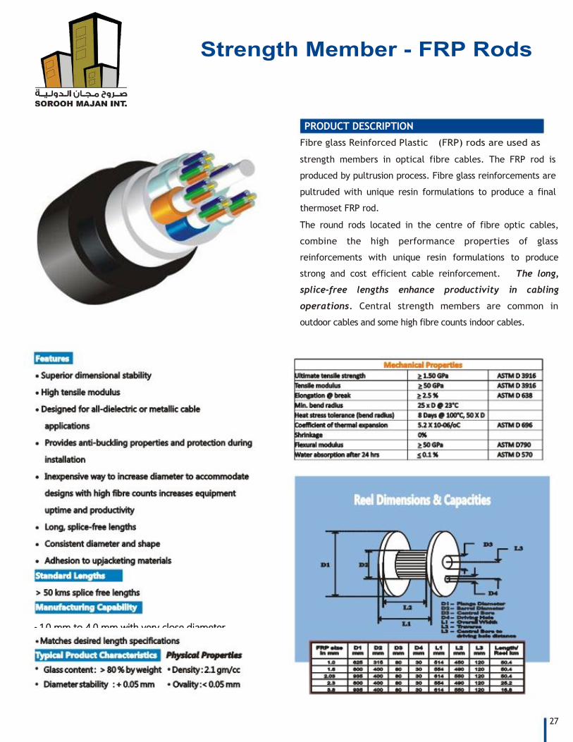
PRODUCT DESCRIPTION
Fibre glass Reinforced Plastic (FRP) rods are used as
strength members in optical fibre cables. The FRP rod is
produced by pultrusion process. Fibre glass reinforcements are
pultruded with unique resin formulations to produce a final
thermoset FRP rod.
The round rods located in the centre of fibre optic cables,
combine the high performance properties of glass
reinforcements with unique resin formulations to produce
strong and cost efficient cable reinforcement. The long,
splice-free lengths enhance productivity in cabling
operations. Central strength members are common in
outdoor cables and some high fibre counts indoor cables.
27
1.0 mm to 4.0 mm with very close diameter
tolerance