introduction sections for editing
TRANSCRIPT


Administrator’s Preface:
The National Airspace System (NAS) Capital Investment Plan, or CIP, provides the agency’s annual update to a rolling five-year plan for all FAA programs funded by the Facilities and Equipment (F&E) appropriation. The F&E funded programs support the development, acquisition, implementation, and sustainment of the systems and services that provide the infrastructure, technology, and capabilities of the NAS. The first year of program funding shown in the CIP is aligned to the F&E request in the corresponding President’s Budget submission; i.e., FY 2018 for this year’s CIP. Each of the next four years of F&E program funding in the CIPare aligned in total to the F&E outyear targets issued annually to the FAA by the Office ofManagement and Budget (OMB).
This year’s FY 2018-2022 NAS CIP includes F&E funding targets of $2.766 billion per year. This five year CIP represents a balance between sustainment and enhancement of the current system and safety capabilities of the NAS and the implementation of the Next Generation Air Transportation System (NextGen).
The FY 2018-2022 NAS CIP provides program information on the scope, objectives, and schedule of FAA’s capital programs. The world class services provided by the NAS support the continued growth of aviation services which annually contribute more than 5% to the U.S. Gross Domestic Product. With the implementation of NextGen and the additional capabilities it provides, the safety and efficiency of the NAS will be further improved in providing benefits to both the aviation service providers and their customers.
I hope the FY 2018-2022 NAS CIP provides you with an understanding of the importance of the capital programs to FAA’s mission and the delivery of the systems and services needed to meet the current and future demands of the NAS.
Sincerely,
Michael P. Huerta, Administrator


i
Table of Contents
1 CAPITAL INVESTMENT PLAN OVERVIEW..................................... 1
1.1 Statutory Requirements ....................................................................................................1
1.2 The Joint Resources Council (JRC) .................................................................................2
1.3 Strategic Priorities and the CIP........................................................................................3
2 KEY CONSIDERATIONS IN CAPITAL PLANNING .......................... 4
2.1 Economic Considerations ..................................................................................................4
2.2 Air Travel Demand ............................................................................................................5
2.3 Airport Expansion Projects ..............................................................................................6
2.4 Sustaining and Improving Infrastructure and System Performance ...........................7
2.5 NAS Resiliency ...................................................................................................................8
2.6 Planning for the Future through NextGen Investments ................................................9
3 AVIATION SAFETY .......................................................................... 10
4 NEXTGEN OPERATIONAL IMPROVEMENTS SUPPORTED BY BUDGET PORTFOLIOS.................................................................... 10
4.1 Relationship of Operational Improvements to NextGen Portfolios and Budget Line Items (BLIs) ......................................................................................................................11
4.2 NextGen Operational Improvement Descriptions ........................................................15
4.3 NextGen Portfolio Descriptions and their supporting Capital Programs ..................23 4.3.1 Separation Management Portfolio ............................................................................23 4.3.2 Traffic Flow Management (TFM) Portfolio .............................................................24 4.3.3 On-Demand NAS Portfolio.......................................................................................24 4.3.4 NAS Infrastructure Portfolio.....................................................................................25 4.3.5 NextGen Support Portfolio at WJHTC .....................................................................25 4.3.6 Unmanned Aircraft Systems (UAS) .........................................................................25 4.3.7 Enterprise, Concept Development, Human Factors, & Demonstrations Portfolio ...26 4.3.8 Performance-Based Navigation & Metroplex Portfolio ...........................................26 4.3.9 System Safety Management Portfolio ......................................................................27 4.3.10 Cross Agency NextGen Management .......................................................................27
ii
5 ENTERPRISE ARCHITECTURE INFRASTRUCTURE ROADMAPS28
5.1 Automation Roadmaps ....................................................................................................29 5.1.1 Air Traffic Management and Air Traffic Control .....................................................31 5.1.2 Air Traffic Support and Oceanic Air Traffic Control ...............................................36 5.1.3 Flight Services and Aeronautical / Information Support ..........................................39
5.2 Communication Roadmaps .............................................................................................43 5.2.1 Telecom and Other Communications .......................................................................44 5.2.2 Voice Switches and Recorders..................................................................................47 5.2.3 Air-to-Ground Voice and Oceanic Communications ...............................................49 5.2.4 Air-to-Ground Data Communications ......................................................................51 5.2.5 Messaging Infrastructure ..........................................................................................53
5.3 Surveillance Roadmaps ...................................................................................................54 5.3.1 En Route Surveillance...............................................................................................55 5.3.2 Terminal Surveillance ...............................................................................................57 5.3.3 Surface, Approach and Cross Domain Surveillance .................................................60
5.4 Navigation Roadmaps ......................................................................................................63 5.4.1 Precision Approach & Safety and Enhancements ....................................................64 5.4.2 Infrastructure and En Route/Terminal/Non-Precision Approach .............................67
5.5 Weather Roadmaps .........................................................................................................70 5.5.1 Weather Sensors........................................................................................................71 5.5.2 Weather Dissemination, Processing, and Display ....................................................75
6 FACILITIES ...................................................................................... 77
7 NAS AND MISSION SUPPORT ......................................................... 79
8 ESTIMATED FUNDING BY BUDGET LINE ITEM (BLI) ................. 81
9 INFORMATION FOR MAJOR CAPITAL PROGRAMS .................... 86
10 CONCLUSION ................................................................................... 92
11 APPENDICES .................................................................................... 93
12 ACRONYMS & ABBREVIATIONS (INCLUDES APPENDICES) ...... 94

iii
List of Figures and Tables:
Figure 2-1 Air Travel Demand Relative to GDP ......................................................................... 5 Figure 5-1 Infrastructure Roadmap Legend .............................................................................. 29 Figure 5-2 Air Traffic Management and Air Traffic Control Roadmap ................................... 31 Figure 5-3 Air Traffic Support and Oceanic Air Traffic Control Roadmap .............................. 36 Figure 5-4 Flight Services and Aeronautical / Information Support Roadmap ......................... 39 Figure 5-5 Telecom and Other Communications Roadmap ...................................................... 44 Figure 5-6 Voice Switches and Recorders Roadmap ................................................................ 47 Figure 5-7 Air-to-Ground Voice and Oceanic Communications Roadmap .............................. 49 Figure 5-8 Air-to-Ground Data Communications Roadmap ..................................................... 52 Figure 5-9 Messaging Infrastructure Roadmap ......................................................................... 53 Figure 5-10 En Route Surveillance Roadmap ............................................................................. 55 Figure 5-11 Terminal Surveillance Roadmap.............................................................................. 57 Figure 5-12 Surface, Approach and Cross Domain Surveillance Roadmap ............................... 60 Figure 5-13 Precision Approach & Safety and Enhancements Roadmap ................................... 64 Figure 5-14 Infrastructure and En Route/Terminal/Non-Precision Approach Roadmap ............ 67 Figure 5-15 Weather Sensors Roadmap ...................................................................................... 71 Figure 5-16 Weather Dissemination, Processing, and Display Roadmap ................................... 75 Table 3-1 Aviation Safety Programs ........................................................................................ 10 Table 4-1 NextGen Operational Improvements (OIs) by Portfolio & Budget Line Item ........ 14 Table 4-2 Separation Management Programs .......................................................................... 24 Table 4-3 Traffic Flow Management Programs ....................................................................... 24 Table 4-4 On-Demand NAS Programs .................................................................................... 25 Table 4-5 NAS Infrastructure Programs .................................................................................. 25 Table 4-6 NextGen Support Portfolio Program ....................................................................... 25 Table 4-7 Unmanned Aircraft Systems (UAS) Programs ........................................................ 26 Table 4-8 Enterprise, Concept Development, Human Factors, & Demonstrations Programs . 26 Table 4-9 Performance Based Navigation & Metroplex Programs ......................................... 27 Table 4-10 System Safety Management Programs .................................................................... 27 Table 4-11 Cross Agency NextGen Management ...................................................................... 27 Table 6-1 Facility Programs ..................................................................................................... 79 Table 7-1 NAS and Mission Support Programs ....................................................................... 80

1
Federal Aviation Administration – National Airspace System
Capital Investment Plan for Fiscal Years 2018–2022 1 Capital Investment Plan Overview The Federal Aviation Administration (FAA) National Airspace System (NAS) Capital Investment Plan (CIP) identifies and describes the capital investments required to sustain and modernize the infrastructure, systems, services, and procedures required for the safe and efficient operation of the NAS. The funding for the capital programs included and described in the CIP are constrained to the Facilities and Equipment (F&E) dollars requested in the President’s Budget and to the outyear F&E targets for the following four years that are issued and updated annually by the Office of Management and Budget (OMB). The FY 2018–2022 CIP Overview includes brief descriptions of the Next Generation Air Transportation System (NextGen) Operational Improvements (OIs) in Section 4 and brief descriptions of all systems and programs that appear on the NAS Enterprise Architecture Roadmaps (EA) in Section 5. Full program descriptions of all the CIP programs are available in Appendix B. The CIP Overview, Appendices A and B, and previous publications of the CIP are available on-line at http://www.faa.gov/air_traffic/publications/cip .
1.1 Statutory Requirements The requirements for the annual publication of the CIP are prescribed by the following statutes.
1. H.R 244 - Consolidated Appropriations Act, 2017 became Public Law 115-31 on May 5, 2017 and provides the appropriation amounts and other direction for the Federal Aviation Administration within DIVISION K—TRANSPORTATION, HOUSING AND URBAN DEVELOPMENT, AND RELATED AGENCIES APPROPRIATIONS ACT, 2017 under Title I—Department of Transportation. For FAA’s Facilities and Equipment appropriation, the following direction is provided regarding the Five Year Capital Investment Plan for the National Airspace System for FY 2018-2022: “Provided further, That no later than March 31, the Secretary of Transportation shall transmit to the Congress an investment plan for the Federal Aviation Administration which includes funding for each budget line item for fiscal years 2018 through 2022, with total funding for each year of the plan constrained to the funding targets for those years as estimated and approved by the Office of Management and Budget.”
2. 49 U.S. Code, section 44501 Plans and Policy, requires FAA to prepare and publish a national airways system plan that reads: “The Administrator of the Federal Aviation Administration shall review, revise, and publish a national airways system plan, known as the Airway Capital Investment Plan, before the beginning of each fiscal year.”

2
The plan shall set forth— (1) for a 10-year period, the research, engineering, and development programs and the facilities and equipment that the Administrator considers necessary for a system of airways, air traffic services, and navigation aids that will— (A) meet the forecasted needs of civil aeronautics; (B) meet the requirements that the Secretary of Defense establishes for the support of the national defense; and (C) provide the highest degree of safety in air commerce
In compliance with the requirements of P.L. 115-31 cited above, an Abbreviated CIP consisting of a brief introduction; planned funding for each CIP program by Budget Line Item (BLI) for FY 2018-2022 in Section 8; and a current status of the major CIP programs in Section 9 was included in the FAA’s FY 2018 President’s Budget submission to Congress in May of 2017. The CIP provides a brief summary of each system and program shown on the NAS Enterprise Architecture Roadmaps in Section 5 which provide a 10 or more year timeline for each system in the NAS in compliance with section 44501 of 49 USC referenced above. The CIP is an integral part of the FAA’s near, mid, and long-term planning and budgeting process. The most recent CIP program descriptions are used as the baseline for the F&E budget formulation and justification process for the next budget year. Specifically, the program descriptions from the FY 2018-2022 CIP will be used as the basis for development of the FY 2019 F&E budget request and the FY 2019-2023 CIP. By integrating the F&E budget formulation process with the preparation and publication of the CIP, the accuracy and consistency of capital program information contained in the budget request with the program descriptions provided in the CIP is assured.
The multi-year view of the CIP helps to define the expected lead times for program acquisition planning. This includes scheduling and preparation of the required artifacts for investment decision briefings to the Joint Resources Council (JRC) as required by FAA’s Acquisition Management System (AMS). Typical AMS milestones include Investment Analysis Readiness Decision (IARD), Initial Investment Decision (IID), and Final Investment Decision (FID). This investment planning and scheduling information may also help interdependent CIP programs to plan and schedule approval, acquisition, and deployment of related systems, equipment, or capabilities into the NAS.
The CIP development process also supports update of the NAS Enterprise Architecture (EA) Infrastructure Roadmaps to ensure that the program information shown on the roadmaps is consistent with the information in both the President’s Budget and the CIP. The roadmaps included in this plan were current as of January 2017. To view the most recent version of the roadmaps see: http://faa.gov/nextgen/delivering/nasea .
1.2 The Joint Resources Council (JRC) In accordance with the AMS, the JRC is responsible for approval of all acquisition programs. The JRC consists of senior level representatives from FAA’s lines of business and provides executive level review, approval, and oversight of the F&E programs included in the CIP.

3
The JRC responsibilities related to the CIP programs include:
• Approval of the FAA investment portfolio each year as part of the F&E budget submission process;
• Annual review and approval of the FAA’s Enterprise Architecture Roadmaps; • Reviews and approves program requests for investment decisions such as IARD, IID, and
FID, and oversees the execution and reporting of acquisition programs; • Approves and establishes baselines for all required AMS program documents including
the program requirements document, acquisition program baseline, business case, and the Implementation Strategy and Planning Document;
• Makes acquisition program baseline change decisions that alter program performance, cost, and schedule baselines during solution implementation for investment programs;
• Conducts quarterly acquisition program reviews to manage ongoing investment programs, including operational assets.
1.3 Strategic Priorities and the CIP
The FAA Administrator has established a strategic framework to define where the agency will focus its efforts. This framework includes high-level Strategic Priorities, as well as Priority Initiatives and related Performance Metrics that will measure how well FAA achieves the priorities. The four Strategic Priorities are:
• Make aviation safer and smarter – There is an imperative to be smarter about how FAA ensures aviation safety because the aviation industry is growing more complex. At the same time, FAA has more safety data than we have ever had before. This provides an opportunity to be more proactive about safety and constantly raise the bar.
• Deliver benefits through technology and infrastructure – The NextGen gives FAA the
opportunity to redefine the National Airspace System for the future and prove that benefits can be delivered to the users of the system. FAA also needs to safely integrate new types of user technologies into the airspace, as well as rebalance existing services and modernize our infrastructure, which will enable us to reduce our costs and become more efficient in the long run.
• Enhance global leadership – Aviation is a global industry. FAA has to continue to be a
world leader in aviation and set the safety standard for others to measure against. FAA needs to be at the table to shape international standards to improve aviation safety and efficiency around the world.
• Empower and innovate with the FAA’s people – The FAA’s employees are the
ultimate driver behind its success, and FAA needs the best and brightest talent with the appropriate leadership and technical skills to transform the FAA and the aviation system as a whole.
The FAA Strategic Priorities help guide the selection of the capital programs to be included in the CIP to support NAS sustainment and modernization through new or improved systems and

4
procedures to meet these priorities and the operating demands on the NAS both now and in the future. Performance Metrics with a target level of achievement have been identified to define progress towards the accomplishment of each Strategic Priority. Each capital program is mapped to the primary Strategic Priority it supports and aligned to the Performance Metric to which it best contributes. The alignment of each CIP program to a Strategic Priority and an associated Performance Metric is shown in Appendix A. A description of how each program contributes to the Performance Metric is found in Appendix B within the section titled Relationship to Performance Metric. 2 Key Considerations in Capital Planning Building a portfolio of capital investments to sustain and modernize the NAS requires significant time to develop, plan, and prioritize program outcomes that may take years to execute and implement. Meeting real-time changes in air traffic demand and future growth may require significant increases in available NAS capacity, efficiency, predictability, and system flexibility. Other considerations include adjustments due to periodic changes in economic conditions; the schedules of ongoing capacity expansion projects at major airports; and the sustainment needed for mission critical Air Traffic Control (ATC) systems, facilities, and other NAS infrastructure. All capital investments must develop a lifecycle cost estimate, be JRC approved, prioritized against other agency priorities, and then funded through the Congressional budget process to meet their approved schedule requirements. Program schedules for new systems must also include sufficient lead time to demonstrate compliance with all NAS reliability and safety standards before they can become operational. By statute, FAA’s total capital investments planned for each year must balance to the latest F&E funding targets issued by OMB. In this process, the JRC must allocate planned funds between the capital programs supporting the ongoing development and deployment of NextGen capabilities with those required to sustain the legacy ATC systems and NAS infrastructure. This approach ensures that current NAS performance levels and safety standards are maintained before, during, and after the transition to NextGen.
2.1 Economic Considerations Access to a reliable worldwide aviation network is essential to the health of the U.S. economy. Both domestic and international commerce rely heavily on ready access to aviation services for carrying passengers and freight to the cities around the world to help sustain economic growth. According to a study on “The Economic Impact of Civil Aviation on the U.S. Economy,” published in November 2016 by the Air Traffic Organization’s Office of Performance Analysis, economic activity attributed to civil aviation-related goods and services during 2014 totaled $1.6 trillion, generating 10.6 million jobs, and $447 billion in earnings. In total, U.S. aviation contributed 5.1 percent to the U.S. Gross Domestic Product (GDP). Other aviation related economic activity for 2014 highlighted in this report includes:
• Air carriers operating in U.S. airspace transported 871.8 million passengers with over 1,230.8 billion Revenue Passenger Miles (RPM).

5
• In support of commercial activities, more than 64.1 billion revenue ton-miles of freight passed through U.S. airports.
• It’s estimated that commercial airline operations enabled $310 billion of visitor expenditures on goods and services.
• Civil aircraft manufacturing, a top U.S. net exporter, had a positive trade balance of $59.9 billion.
2.2 Air Travel Demand
Historically, demand for air travel is heavily influenced by changes in the economy. Figure 2-1 depicts the total percentage change in RPM and GDP (in constant 2009 dollars) since 1977. Over the last 38 years, passenger demand for air travel (RPM) has grown at a faster rate than the economy (GDP) as shown below.
Total Percent Growth in RPM and GDP Since 1977
Figure 2-1 Air Travel Demand Relative to GDP1
The U.S. inflation-adjusted, i.e. real, economic output long-term growth trend supports the continuing increases in air travel. Recent economic data shows that GDP is continuing to grow and the trend lines in figure 2-1 suggest there continues to be a corresponding increase in the demand for air travel, as measured by RPM. 1 Sources: U.S. Department of Commerce, Bureau of Economic Analysis and U.S. Department of Transportation, Bureau of Transportation Statistics
0%
50%
100%
150%
200%
250%
300%
350%
400%
Perc
ent C
hang
e fr
om 1
977
Revenue Passenger Miles(RPM)
Gross Domestic Product(GDP)
6
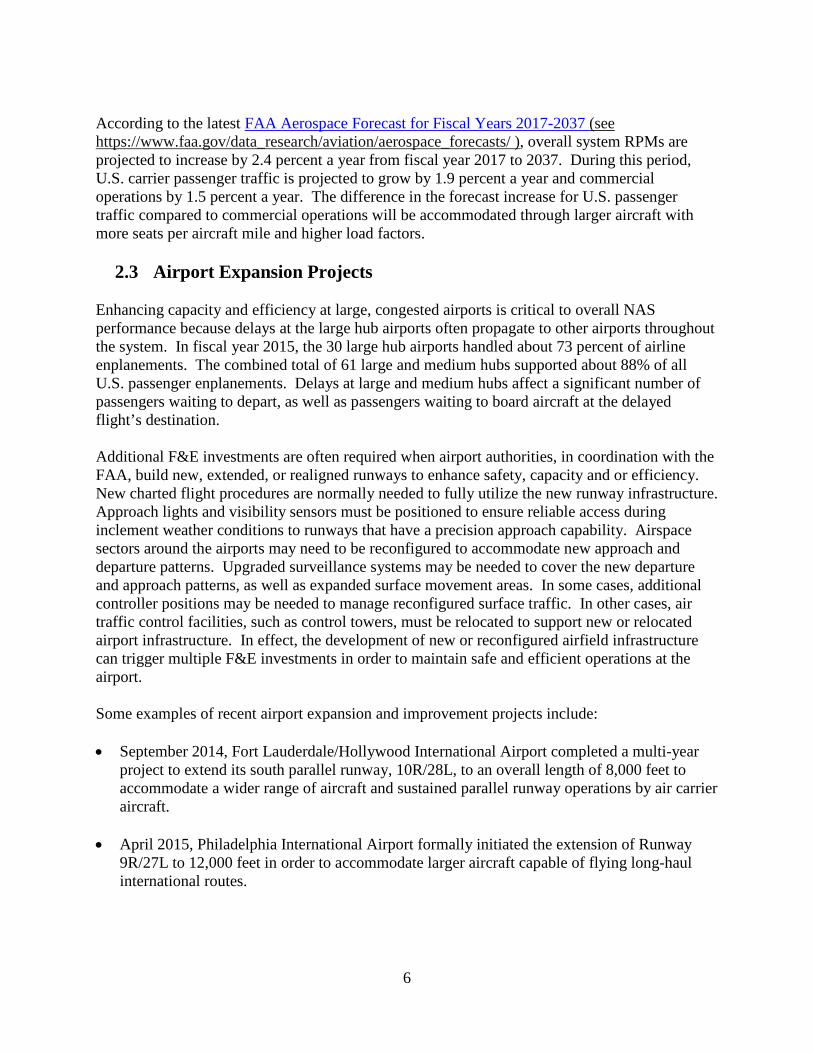
According to the latest FAA Aerospace Forecast for Fiscal Years 2017-2037 (see https://www.faa.gov/data_research/aviation/aerospace_forecasts/ ), overall system RPMs are projected to increase by 2.4 percent a year from fiscal year 2017 to 2037. During this period, U.S. carrier passenger traffic is projected to grow by 1.9 percent a year and commercial operations by 1.5 percent a year. The difference in the forecast increase for U.S. passenger traffic compared to commercial operations will be accommodated through larger aircraft with more seats per aircraft mile and higher load factors.
2.3 Airport Expansion Projects Enhancing capacity and efficiency at large, congested airports is critical to overall NAS performance because delays at the large hub airports often propagate to other airports throughout the system. In fiscal year 2015, the 30 large hub airports handled about 73 percent of airline enplanements. The combined total of 61 large and medium hubs supported about 88% of all U.S. passenger enplanements. Delays at large and medium hubs affect a significant number of passengers waiting to depart, as well as passengers waiting to board aircraft at the delayed flight’s destination. Additional F&E investments are often required when airport authorities, in coordination with the FAA, build new, extended, or realigned runways to enhance safety, capacity and or efficiency. New charted flight procedures are normally needed to fully utilize the new runway infrastructure. Approach lights and visibility sensors must be positioned to ensure reliable access during inclement weather conditions to runways that have a precision approach capability. Airspace sectors around the airports may need to be reconfigured to accommodate new approach and departure patterns. Upgraded surveillance systems may be needed to cover the new departure and approach patterns, as well as expanded surface movement areas. In some cases, additional controller positions may be needed to manage reconfigured surface traffic. In other cases, air traffic control facilities, such as control towers, must be relocated to support new or relocated airport infrastructure. In effect, the development of new or reconfigured airfield infrastructure can trigger multiple F&E investments in order to maintain safe and efficient operations at the airport. Some examples of recent airport expansion and improvement projects include: • September 2014, Fort Lauderdale/Hollywood International Airport completed a multi-year
project to extend its south parallel runway, 10R/28L, to an overall length of 8,000 feet to accommodate a wider range of aircraft and sustained parallel runway operations by air carrier aircraft.
• April 2015, Philadelphia International Airport formally initiated the extension of Runway 9R/27L to 12,000 feet in order to accommodate larger aircraft capable of flying long-haul international routes.

7
• October 2015, Chicago O’Hare International Airport completed and opened a new 7,500-foot runway, 10R/28L. Then in 2016, Chicago O’Hare International Airport began construction on runway 9C/27C; the airport's sixth parallel runway, which is expected to open in 2020.
2.4 Sustaining and Improving Infrastructure and System Performance
The air traffic control system requires very high reliability and availability. Aircraft operating in controlled airspace and while on the airport surface must maintain safe separation from other aircraft. To ensure safe separation, reliable communication, navigation and surveillance systems are required. Each system operating in the NAS has a high level of redundancy to support system reliability and availability to minimize service disruptions. Before these systems reach the end of their service life, planning for their replacement must be well underway to reduce the risk of performance degradation or outages in the event that replacement parts become obsolete or are otherwise difficult to obtain. The air traffic control infrastructure is a complex system made up of several thousand components that control air traffic approaching, landing and departing from airports. This includes 21 Air Route Traffic Control Centers (ARTCC) that house the automation equipment used by air traffic controllers to control en route air traffic; over 500 Air Traffic Control Towers (ATCT); and 168 Terminal Radar Approach Control (TRACON) facilities. This daily flow of air traffic is dependent on several hundred surveillance and weather radars; navigation systems for en route and airport approach guidance; and thousands of radios that allow pilots and air traffic controllers to be in continuous contact during an aircraft’s flight. NextGen will incrementally replace and upgrade much of this equipment as new technologies and procedures are introduced to improve efficiency in air traffic control. Some legacy equipment, such as communication, navigation, and surveillance systems must remain in operation to supplement or backup NextGen capabilities. Many current buildings that house existing ATC equipment will also be needed for the NextGen systems. To sustain the high level of NAS reliability and availability required to ensure the safety and efficiency of flight, continued investment in the maintenance and improvement of these buildings and other legacy infrastructure is required. As of July 2017, the air traffic control infrastructure had a repair backlog estimated at $4.3B in unfunded requirements to sustain its facilities. Goals, objectives, strategies, processes, and priorities have been established to address this challenge. Nine systemic issues have been identified across the Air Traffic Organization (ATO) that includes Fire Life Safety, Fall Protection, Guyed Towers, Arc Flash, Power Cable, Engine Generators, Fuel Storage Tanks, ARTCC Chiller replacement, and ARTCC Critical Essential Power System replacement. As requested in the FY 2018 President’s Budget, the ATC Facilities Sustainment Strategic Plan focuses on the following budget line items for sustaining the NAS.
• Air Route Traffic Control Center (ARTCC) & Combined Control Facility (CCF) Building Improvements, BLI 2A04;
• Air Traffic Control En Route Radar Facilities Improvements, BLI 2A07; • Terminal Air Traffic Control Facilities – Replace, BLI 2B05;
8
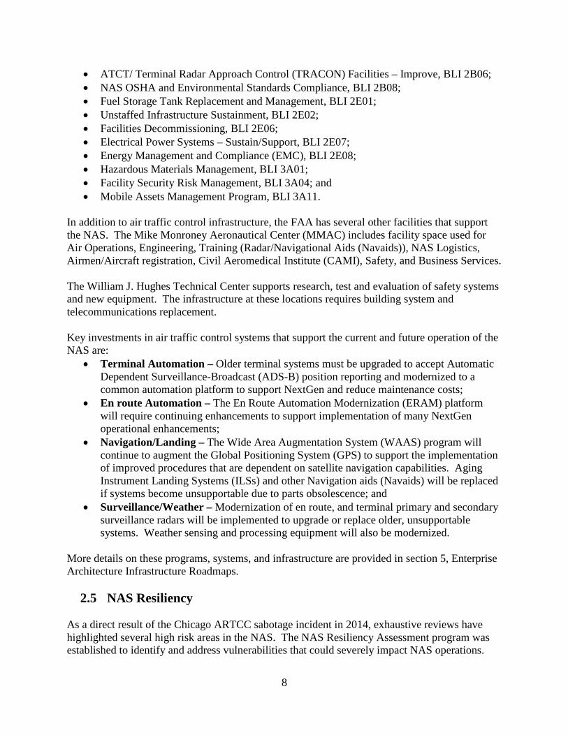
• ATCT/ Terminal Radar Approach Control (TRACON) Facilities – Improve, BLI 2B06; • NAS OSHA and Environmental Standards Compliance, BLI 2B08; • Fuel Storage Tank Replacement and Management, BLI 2E01; • Unstaffed Infrastructure Sustainment, BLI 2E02; • Facilities Decommissioning, BLI 2E06; • Electrical Power Systems – Sustain/Support, BLI 2E07; • Energy Management and Compliance (EMC), BLI 2E08; • Hazardous Materials Management, BLI 3A01; • Facility Security Risk Management, BLI 3A04; and • Mobile Assets Management Program, BLI 3A11.
In addition to air traffic control infrastructure, the FAA has several other facilities that support the NAS. The Mike Monroney Aeronautical Center (MMAC) includes facility space used for Air Operations, Engineering, Training (Radar/Navigational Aids (Navaids)), NAS Logistics, Airmen/Aircraft registration, Civil Aeromedical Institute (CAMI), Safety, and Business Services. The William J. Hughes Technical Center supports research, test and evaluation of safety systems and new equipment. The infrastructure at these locations requires building system and telecommunications replacement. Key investments in air traffic control systems that support the current and future operation of the NAS are:
• Terminal Automation – Older terminal systems must be upgraded to accept Automatic Dependent Surveillance-Broadcast (ADS-B) position reporting and modernized to a common automation platform to support NextGen and reduce maintenance costs;
• En route Automation – The En Route Automation Modernization (ERAM) platform will require continuing enhancements to support implementation of many NextGen operational enhancements;
• Navigation/Landing – The Wide Area Augmentation System (WAAS) program will continue to augment the Global Positioning System (GPS) to support the implementation of improved procedures that are dependent on satellite navigation capabilities. Aging Instrument Landing Systems (ILSs) and other Navigation aids (Navaids) will be replaced if systems become unsupportable due to parts obsolescence; and
• Surveillance/Weather – Modernization of en route, and terminal primary and secondary surveillance radars will be implemented to upgrade or replace older, unsupportable systems. Weather sensing and processing equipment will also be modernized.
More details on these programs, systems, and infrastructure are provided in section 5, Enterprise Architecture Infrastructure Roadmaps.
2.5 NAS Resiliency As a direct result of the Chicago ARTCC sabotage incident in 2014, exhaustive reviews have highlighted several high risk areas in the NAS. The NAS Resiliency Assessment program was established to identify and address vulnerabilities that could severely impact NAS operations.
9
Identifying and assessing the programs critical to ensuring resiliency will result in the development of specialized programmatic and technical recommendations to target investments to improve the resiliency of critical NAS services at Tier 1 facilities. These are the facilities, systems and services whose interruption would result in less than 90% of normal operating rates for more than 24 hours at core Airports and/or 96 hours for the En Route ATC domain. Funding for NAS Resiliency activities has been requested within the programs for the relevant systems, facilities, and infrastructure to be addressed.
2.6 Planning for the Future through NextGen Investments NextGen is the name of the ongoing transformation of the NAS to ensure that future safety, capacity, and environmental requirements will be met by the FAA. The NextGen vision and goals are supported by many capital programs that collectively will fundamentally change the way air traffic is managed by combining new technologies for surveillance, navigation, and communications with automation system enhancements, workforce training, procedural changes, and airfield development. These improvements will also facilitate the integration of commercial space and the operation of unmanned aircraft systems into the NAS. NextGen advances will enable precise monitoring of aircraft both on the ground and in flight; allow direct routes for travel between cities; improve decision support to strategically manage traffic flows on busy routes; and leverage precision navigation to improve utilization of existing airspace and runway capacity. Having achieved many of the milestones needed for this transformation FAA is already realizing benefits from NextGen. More information concerning the vision, benefits, and implementation details can be found in the NextGen Implementation Plan at http://www.faa.gov/nextgen/library/ . Development of NextGen Operational Improvements (OIs) can include concept development, modeling changes in ATC performance, safety analyses, demonstration of new capabilities, international coordination, standards development, and other pre-implementation activities. When a new concept is developed and adopted, the improvement may be implemented through procedural changes, system enhancements, airspace changes, training, and upgrades to aircraft avionics as necessary. The CIP programs support the activities leading up to the initial investment decisions for implementation. When fully developed, a program solution is baselined for acquisition and implementation. More information on the NextGen OIs can be found in section 4. Some of the larger NextGen programs that provide the foundation for the introduction of new NextGen OIs are:
• En Route Automation Modernization (ERAM) – Enhancements 2 and 3 and Sustainment 2 and 3 – These programs will be upgrading the ERAM software to support NextGen OIs and provides replacement hardware for the ERAM system (BLI 2A01);
• System Wide Information Management (SWIM) – SWIM provides the standards, hardware and software to enable information management and data sharing required to support NextGen. This includes Common Support Services – Weather (CSS-Wx) which provides access for NAS users to a unified aviation weather picture (BLI 2A11);
10
• Automatic Dependent Surveillance – Broadcast (ADS-B) NAS Wide Implementation (ADS-B) – ADS-B provides more accurate and timely surveillance data needed to allow direct routing and conflict free routes (BLI 2A12);
• NextGen Weather Processor (NWP) – This program will establish a common weather processing platform which will provide improved weather products and support more efficient operations (BLI 2A16);
• Data Communications in support of NextGen – Data Comm provides data link communications between controller and pilot to facilitate information transfer, reduce workload and minimize potential errors in communication of flight plan adjustments (BLI 2A18);
• National Airspace System Voice System (NVS) – NVS will provide a nationwide network of digital voice switches for terminal and en route air traffic facilities. These new systems will provide voice switch configuration flexibility required to support facility backup (BLI 2B12); and
• Aeronautical Information Management (AIM) Program – AIM provides digital aeronautical information to NAS users (BLI 4A09).
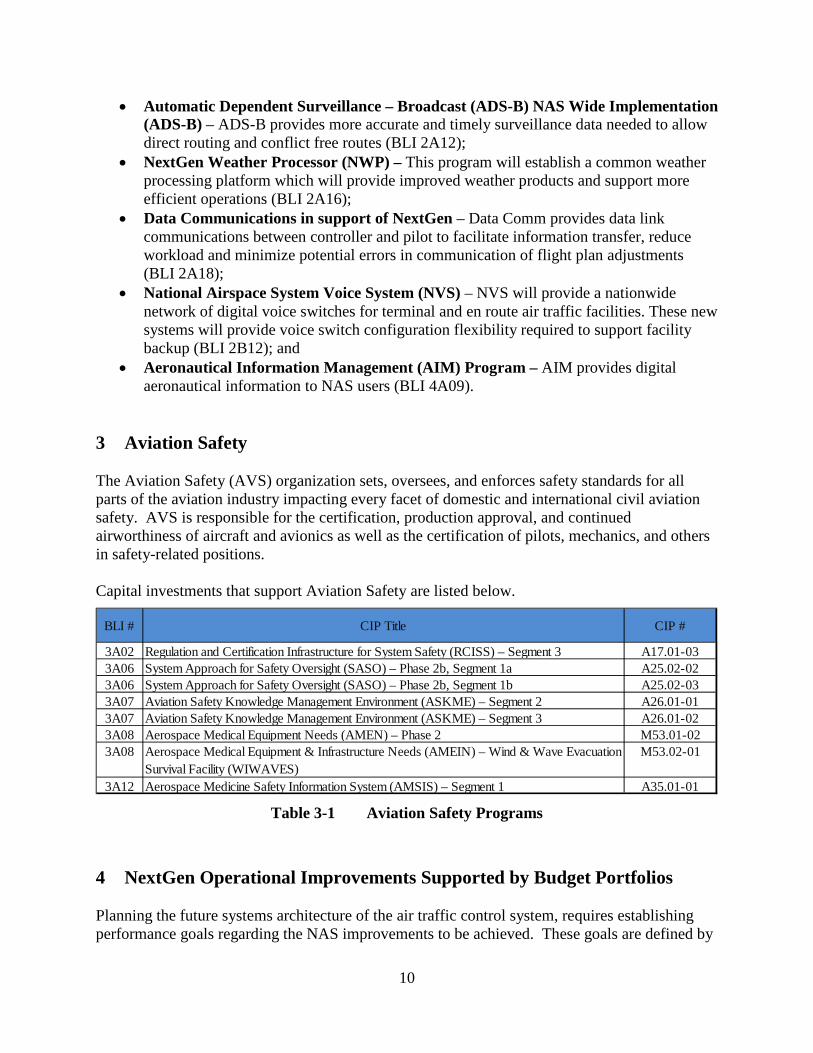
3 Aviation Safety The Aviation Safety (AVS) organization sets, oversees, and enforces safety standards for all parts of the aviation industry impacting every facet of domestic and international civil aviation safety. AVS is responsible for the certification, production approval, and continued airworthiness of aircraft and avionics as well as the certification of pilots, mechanics, and others in safety-related positions. Capital investments that support Aviation Safety are listed below.
Table 3-1 Aviation Safety Programs
4 NextGen Operational Improvements Supported by Budget Portfolios Planning the future systems architecture of the air traffic control system, requires establishing performance goals regarding the NAS improvements to be achieved. These goals are defined by
BLI # CIP Title CIP #
3A02 Regulation and Certification Infrastructure for System Safety (RCISS) – Segment 3 A17.01-033A06 System Approach for Safety Oversight (SASO) – Phase 2b, Segment 1a A25.02-023A06 System Approach for Safety Oversight (SASO) – Phase 2b, Segment 1b A25.02-033A07 Aviation Safety Knowledge Management Environment (ASKME) – Segment 2 A26.01-013A07 Aviation Safety Knowledge Management Environment (ASKME) – Segment 3 A26.01-023A08 Aerospace Medical Equipment Needs (AMEN) – Phase 2 M53.01-023A08 Aerospace Medical Equipment & Infrastructure Needs (AMEIN) – Wind & Wave Evacuation
Survival Facility (WIWAVES)M53.02-01
3A12 Aerospace Medicine Safety Information System (AMSIS) – Segment 1 A35.01-01

11
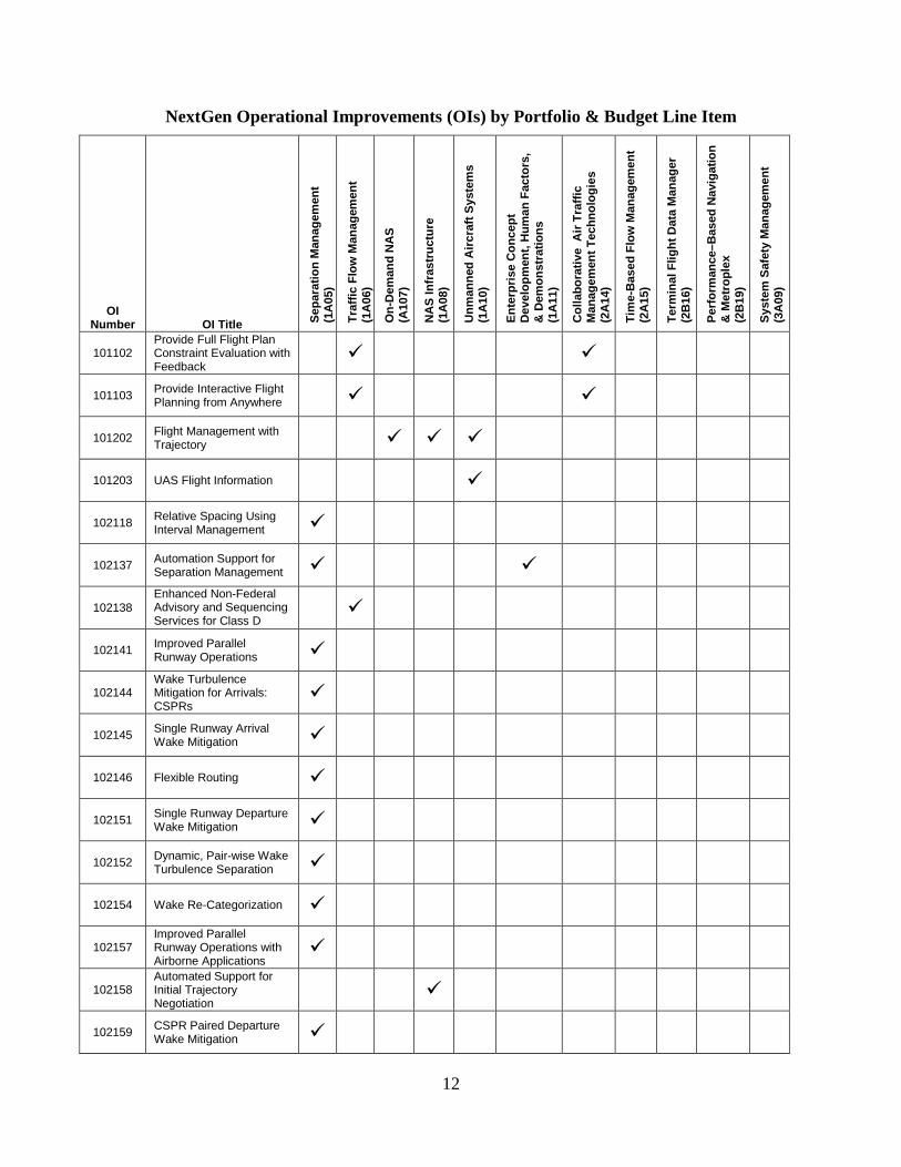
the Operational Improvements (OIs) that describe specific operational performance enhancements to be realized through the NextGen investments. The table below lists the NextGen OIs and shows the corresponding NextGen portfolios and Budget Line Items (BLIs) from which these investments will be made. The OIs included in this section are targeted for development and implementation within the FY 2018-2022 timeframe. The NextGen concept development and implementation work is focused on expanding and realizing NextGen through the development and implementation of the transformational NextGen systems which deliver improved services to users, by seamlessly integrating data to ensure that the FAA and stakeholders have a common understanding of current and future NAS status, improving strategic planning and increasing flexibility, and by meeting new challenges such as cybersecurity and incorporating new entrants.
4.1 Relationship of Operational Improvements to NextGen Portfolios and Budget Line Items (BLIs)
The relationship between the OIs, the NextGen Portfolios, and the BLIs is displayed in the following table and shows each OI to the corresponding portfolios and the BLIs from which they are funded. The NextGen Portfolios are identified across the top of the table with the BLI number shown in parenthesis. On the left side of the table are the OI numbers and titles. The check marks to the right of an OI denote the portfolios to which the development or implementation work contributes. A description of each OI is provided in section 4.2 following the table on the next page. In section 4.3, a description of each development portfolio is provided. For information on the implementation portfolios, Collaborative Air Traffic Management Technologies (CATMT), Time-Based Flow Management (TBFM), and Terminal Flight Data Manager (TFDM), please refer to the Enterprise Architecture Infrastructure Automation Roadmaps in Section 5.1. For CATMT and TBFM, see section 5.1.1 Air Traffic Management and Air Traffic Control. For TFDM, see section 5.1.2 – Air Traffic Support and Oceanic Air Traffic Control.
12
NextGen Operational Improvements (OIs) by Portfolio & Budget Line Item
OI Number
OI Title Sepa
ratio
n M
anag
emen
t
(1A
05)
Traf
fic F
low
Man
agem
ent
(1A
06)
On-
Dem
and
NA
S
(A10
7)
NA
S In
fras
truc
ture
(1
A08
)
Unm
anne
d A
ircra
ft Sy
stem
s (1
A10
)
Ente
rpris
e C
once
pt
Dev
elop
men
t, H
uman
Fac
tors
, &
Dem
onst
ratio
ns
(1A
11)
Col
labo
rativ
e A
ir Tr
affic
M
anag
emen
t Tec
hnol
ogie
s (2
A14
) Ti
me-
Bas
ed F
low
Man
agem
ent
(2A
15)
Term
inal
Flig
ht D
ata
Man
ager
(2
B16
) Pe
rfor
man
ce–B
ased
Nav
igat
ion
& M
etro
plex
(2
B19
) Sy
stem
Saf
ety
Man
agem
ent
(3A
09)
101102 Provide Full Flight Plan Constraint Evaluation with Feedback
101103 Provide Interactive Flight Planning from Anywhere
101202 Flight Management with Trajectory
101203 UAS Flight Information
102118 Relative Spacing Using Interval Management
102137 Automation Support for Separation Management
102138 Enhanced Non-Federal Advisory and Sequencing Services for Class D
102141 Improved Parallel Runway Operations
102144 Wake Turbulence Mitigation for Arrivals: CSPRs
102145 Single Runway Arrival Wake Mitigation
102146 Flexible Routing
102151 Single Runway Departure Wake Mitigation
102152 Dynamic, Pair-wise Wake Turbulence Separation
102154 Wake Re-Categorization
102157 Improved Parallel Runway Operations with Airborne Applications
102158 Automated Support for Initial Trajectory Negotiation
102159 CSPR Paired Departure Wake Mitigation

13
OI Number
OI Title Se
para
tion
Man
agem
ent
(1A
05)
Traf
fic F
low
Man
agem
ent
(1A
06)
On-
Dem
and
NA
S
(A10
7)
NA
S In
fras
truc
ture
(1
A08
)
Unm
anne
d A
ircra
ft Sy
stem
s (1
A10
)
Ente
rpris
e C
once
pt
Dev
elop
men
t, H
uman
Fac
tors
, &
Dem
onst
ratio
ns
(1A
11)
Col
labo
rativ
e A
ir Tr
affic
M
anag
emen
t Tec
hnol
ogie
s (2
A14
)
Tim
e-B
ased
Flo
w M
anag
emen
t (2
A15
)
Term
inal
Flig
ht D
ata
Man
ager
(2
B16
)
Perf
orm
ance
–Bas
ed
Nav
igat
ion
& M
etro
plex
(2
B19
) Sy
stem
Saf
ety
Man
agem
ent
(3A
09)
102160 Advanced Automation Support for Separation Management
103119 Initial Integration of Weather Information into NAS Automation and
103123 Full Integration of Weather Information into NAS Automation and
103210 Aircraft Collision Avoidance for New Aircraft Types
103305 On-Demand NAS Information
103306 Tailored Delivery of On-Demand NAS Information
104102 Optimized Oceanic Trajectories via Interactive Planning
104115 Current Tactical Management of Flow in En Route for Arrivals and
104117 Improved Management of Arrival/Surface/Departure Flow Operations
104120 Point-in-Space Metering
104122 Integrated Arrival and Departure Airspace Management
104123 Time-Based Metering Using RNAV and RNP Route Assignments
104126 Trajectory-Based Management – Gate-to-Gate
104128 Time-Based Metering in the Terminal Environment
104206 Full Surface Traffic Management with Conformance Monitoring
104208 Enhanced Departure Flow Operations
104211 Surface Traffic Management

14
OI Number
OI Title Se
para
tion
Man
agem
ent
(1A
05)
Traf
fic F
low
Man
agem
ent
(1A
06)
On-
Dem
and
NA
S
(A10
7)
NA
S In
fras
truc
ture
(1
A08
)
Unm
anne
d A
ircra
ft Sy
stem
s (1
A10
)
Ente
rpris
e C
once
pt
Dev
elop
men
t, H
uman
Fac
tors
, &
Dem
onst
ratio
ns
(1A
11)
Col
labo
rativ
e A
ir Tr
affic
M
anag
emen
t Tec
hnol
ogie
s (2
A14
)
Tim
e-B
ased
Flo
w M
anag
emen
t (2
A15
)
Term
inal
Flig
ht D
ata
Man
ager
(2
B16
)
Perf
orm
ance
–Bas
ed
Nav
igat
ion
& M
etro
plex
(2
B19
)
Syst
em S
afet
y M
anag
emen
t (3
A09
)
105207 Full Collaborative Decision Making
105208 Traffic Management Initiatives with Flight-Specific Trajectories
105302 Initial Flight Day Evaluation
105303 Advanced Flight Day Evaluation
107120 Resilient PBN Operations
108206 Flexible Airspace Management
108209
Increase Capacity and Efficiency Using Area Navigation (RNAV) and Required Navigation Performance (RNP)
108212 Improved Management of Special Activity Airspace (SAA)
108214 UAS Airspace Access
108215 Increase Capacity and Efficiency Using Streamlined PBN
601103 Safety Information Sharing and Emergent Trend Detection
601104 Automated Safety Information Sharing and Analysis
601202 Integrated Safety Analysis and Modeling
601302 Increase International Cooperation for Aviation Safety
Table 4-1 NextGen Operational Improvements (OIs) by Portfolio & Budget Line Item
15
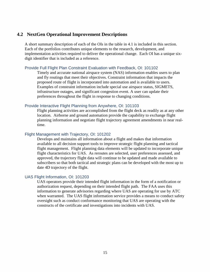
4.2 NextGen Operational Improvement Descriptions A short summary description of each of the OIs in the table in 4.1 is included in this section. Each of the portfolios contributes unique elements to the research, development, and implementation activities required to deliver the operational change. Each OI has a unique six-digit identifier that is included as a reference. Provide Full Flight Plan Constraint Evaluation with Feedback, OI: 101102
Timely and accurate national airspace system (NAS) information enables users to plan and fly routings that meet their objectives. Constraint information that impacts the proposed route of flight is incorporated into automation and is available to users. Examples of constraint information include special use airspace status, SIGMETS, infrastructure outages, and significant congestion event. A user can update their preferences throughout the flight in response to changing conditions.
Provide Interactive Flight Planning from Anywhere, OI: 101103
Flight planning activities are accomplished from the flight deck as readily as at any other location. Airborne and ground automation provide the capability to exchange flight planning information and negotiate flight trajectory agreement amendments in near real-time.
Flight Management with Trajectory, OI: 101202
Develops and maintains all information about a flight and makes that information available to all decision support tools to improve strategic flight planning and tactical flight management. Flight planning data elements will be updated to incorporate unique flight characteristics for UAS. As reroutes are selected, user preferences assessed, and approved, the trajectory flight data will continue to be updated and made available to subscribers so that both tactical and strategic plans can be developed with the most up to date 4D trajectory of the flight.
UAS Flight Information, OI: 101203
UAS operators provide their intended flight information in the form of a notification or authorization request, depending on their intended flight path. The FAA uses this information to generate advisories regarding where UAS are operating for use by ATC when warranted. The UAS flight information service provides a means to conduct safety oversight such as conduct conformance monitoring that UAS are operating with the constructs of the certificate and investigations into incidents with UAS.
16
Relative Spacing Using Interval Management, OI: 102118 Improved inter-aircraft spacing precision is achieved using new aircraft capabilities, which should increase efficiency and throughput in capacity-constrained airspace without negatively impacting controller workload and task complexity. This will improve overall traffic flow and help avoid some costly, low-altitude maneuvering. This will be used in locations that do not have or are not currently conducting time based flow management.
Automation Support for Separation Management, OI: 102137
Air Navigation Service Provider (ANSP) automation provides the controller with tools to manage aircraft separation in a mixed navigation and wake performance environment. Advances in Performance Based Navigation and additional wake separation categories leads to the use of more sophisticated separation rules between aircraft and the need for advisory support to the controller.
Enhanced Non-Federal Advisory and Sequencing Services for Class D Airport Operations, OI: 102138
Improved surveillance, communications, and decision support capabilities used by personnel located in a remote ground level facility may provide a more cost effective solution for providing advisory and sequencing services in class D airspace. This will enable faster confirmation that the runway is clear thereby enabling more consistent airport services and additional operations, especially during Instrument Meteorological Conditions (IMC) and enable these services to be provided for more airports across the NAS.
Improved Parallel Runway Operations, OI: 102141
This improvement will explore concepts to recover lost capacity through reduced separation standards and increased application of advanced dependent and independent procedures.
Wake Turbulence Mitigation for Arrivals: CSPRs, OI: 102144
This improvement will implement additional controller tools and procedures that increase arrival throughput for dependent parallel approach courses to closely spaced parallel runways (CSPR).
Single Runway Arrival Wake Mitigation, OI: 102145
Single Runway Arrival Wake Mitigation will provide increased arrival capacity to single runways by reducing longitudinal wake separation standards during radar operations under certain crosswind conditions. Weather sensors and wind prediction systems will be used to forecast persistent crosswind conditions and air traffic automation systems will be used to indicate to controllers when they can safely reduce wake separation standards, increasing arrival capacity.

17
Flexible Routing, OI: 102146 Increased system precision and enhanced automation supports the efficient use of flight levels so that aircraft can more closely fly routes that maximize the airlines' goals of fuel efficiency, aircraft operations, and schedule. Aircraft provide state and intent data that will lead to fewer predicted problems resulting in fewer diversions from the preferred routing.
Single Runway Departure Wake Mitigation, OI: 102151
Single Runway Departure Wake Mitigation will provide increased departure capacity from single runways by reducing longitudinal wake separation standards under certain crosswind conditions. Airport weather sensors and wind predictions systems will be used to forecast persistent crosswind conditions and monitor crosswind conditions. Air traffic automation systems will be used to indicate to controllers when they can safely reduce wake separation standards, increasing departure capacity.
Dynamic, Pair-wise Wake Turbulence Separation, OI: 102152
Wake turbulence separation procedures and applications supporting en route and terminal operations are integrated into air traffic automation to provide dynamic, pairwise, lateral, longitudinal, and vertical wake separation requirements for trajectory management based on aircraft and weather conditions, in real time.
Wake Re-Categorization, OI: 102154
The current set of pairwise wake separation requirements have been updated and expanded based on analysis of wake generation, wake decay and encounter effects for the current fleet of aircraft. These new separation standards are programmed into the automation systems to allow the controllers to use more accurate aircraft separation standards to increase both flight efficiency and runway capacity utilization.
Improved Parallel Runway Operations with Airborne Applications, OI: 102157
Improved flight deck capabilities allow for increased arrival capacity for parallel runway operations in IMC. Reduced separation for dependent approaches of closely spaced parallel runways will be enhanced using aircraft avionics that assist pilots in maintaining the required interval from other aircraft. Ground automation identifies opportunities to the controller who can provide a clearance to the flight crew for specific lateral and longitudinal separation distance from other aircraft.
Automated Support for Initial Trajectory Negotiation, OI: 102158
En Route sector capacity and throughput are increased through the ability to send route changes and instructions to the cockpit over data communications. Trajectory management is enhanced by automated assistance to negotiate pilot trajectory change requests with properly equipped aircraft operators.

18
CSPR Paired Departure Wake Mitigation, OI: 102159 Changes in procedures, standards, and the implementation of new technology will safely reduce the impact of wake separation standards on airport operations. Changes to wake separation minima implemented at airports with CSPR complexes will increase throughput during departure operations during periods with favorable winds.
Advanced Automation Support for Separation Management, OI: 102160
ANSP automation provides the controller with tools to manage aircraft separation with more advanced wake separation standards and performance based navigation capabilities. Controllers will use ANSP automation enhancements to obtain additional situational awareness to decrease the cognitive workload and increase the operational benefit afforded by more closely spaced routes.
Initial Integration of Weather Information into NAS Automation and Decision Making, OI: 103119
Advances in weather information content and dissemination provide users and/or their decision support tools with the ability to identify specific weather impacts on operations (e.g., trajectory management and impacts on specific airframes, arrival/departure planning) to ensure continued safe and efficient flight.
Full Integration of Weather Information into NAS Automation and Decision Making, OI: 103123
Weather information will be translated into constraint information to be fully integrated into decision-support technologies. Advanced impact assessment tools improve ANSP and flight operator tactical and strategic planning by providing consolidated weather processing of observational and forecast capabilities to produce consistent weather information for improved ATM decision-making for meeting capacity, efficiency, and safety objectives.
Aircraft Collision Avoidance for New Aircraft Types, OI: 103210
New technologies will benefit aircraft-based Collision Avoidance (CA) avionics as they are extended to accommodate Unmanned Aircraft Systems. The CA technologies will process non-cooperative surveillance targets in order to sense/detect and avoid other aircraft. In addition, the logic will also account for the variety of aircraft sizes and dynamic capabilities of the aircraft.
On-Demand NAS Information, OI: 103305
NAS and aeronautical information will be available to users on demand. This information is consistent across applications and locations that are available to authorized subscribers and equipped aircraft. Proprietary and security-sensitive information is not shared with unauthorized agencies or individuals.

19
Tailored Delivery of On-Demand NAS Information, OI: 103306 The delivery of selected NAS and aeronautical information data elements will be available to users and tailored based on the information that pertains to their flight trajectory. An integrated set of weather information will be available to users on demand and tailored based on their flight trajectory. This information is consistent across applications and locations that are available to authorized subscribers and equipped aircraft.
Optimized Oceanic Trajectories via Interactive Planning, OI: 104102
Interactive planning between the oceanic airspace user and FAA automation both before and after departure enhances the ability of the flight to fly closer to the user’s preferred 4D trajectory. Users can receive feedback on their intended Oceanic trajectory and adjust plans if desired. Given the long duration of oceanic flights, there are often changes to wind and weather conditions while the flight progresses which change the flight’s progress along the route. The exchange of the route information from the aircraft provides the FAA with more up to date location information. Automation improvements allow the user to more easily request trajectory changes that better fit the new conditions.
Current Tactical Management of Flow in En Route for Arrivals and Departures, OI: 104115
Automation will assist with minimizing the capacity and efficiency impacts of special activity airspace closures using integrated tools based on mature Aeronautical Information Exchange models.
Improved Management of Arrival/Surface/Departure Flow Operations, OI: 104117
This improvement integrates advanced arrival/departure flow management with advanced surface operation techniques to improve overall airport capacity and efficiency.
Point-in-Space Metering, OI: 104120
The ANSP uses scheduling tools and trajectory-based operations to assure smooth flow of traffic and increase the efficient use of airspace. Point-in-space metering can be associated with a departure fix, arrival fix, or any other point-in-space, such as airspace boundaries or other flow converging points. Decision support tools will allow traffic managers to develop scheduled arrival times for constrained resources and allow controllers to manage aircraft trajectories to meet the scheduled meter times.
Integrated Arrival and Departure Airspace Management, OI: 104122
New airspace design takes advantage of expanded use of terminal procedures and separation standards. This is particularly applicable in major metropolitan areas supporting multiple high-volume airports. This increases aircraft flow and introduces additional routes and flexibility to reduce delays.
20
Time-Based Metering Using RNAV and RNP Route Assignments, OI: 104123 RNAV, RNP and time-based metering provide efficient use of runways and airspace in high-density airport environments. RNAV and RNP provide users with more efficient and consistent arrival and departure routings and fuel-efficient operations. Metering automation will be augmented to provide additional options to manage the flow of aircraft to meter fixes, thus permitting more efficient use of runways and airspace. Decision support tool functions will be implemented in traffic management tools and procedures to assist air traffic management in selecting the routes configurations that optimize airspace in the Metroplex environment.
Trajectory-Based Management – Gate-to-Gate, OI: 104126
All aircraft operating in high-density airspace are managed by Four Dimensional Trajectories (4DT) to dramatically reduce the uncertainty of an aircraft's future flight path. Integration of these improved time estimates into separation assurance and traffic management tools results in more efficient tactical adjustment of individual aircraft trajectories and increased capacity and throughput. Trajectory exchange through data communications will significantly contribute to this improvement.
Time-Based Metering in the Terminal Environment, OI: 104128 This improvement extends current metering capabilities into the terminal environment and furthers the pursuit of end-to-end metering and trajectory-based operations. It also supports capabilities designed to expand the use of terminal separation standards in transition airspace, and solidifies the foundation for future advanced airborne-based applications that will depend upon ground-based automation to maintain the complete sequence of aircraft into and out of high-density terminal locations.
Full Surface Traffic Management with Conformance Monitoring, OI: 104206
Efficiency and safety of surface traffic management is increased using improved automation support for taxi route planning, data link of taxi instructions, and automated conformance monitoring of the aircraft to the approved taxi clearance.
Enhanced Departure Flow Operations, OI: 104208 Efficient departure operations are achieved through the improved ability to quickly revise departure clearances in the event that changing weather, winds or system constraints requires amendments to the pre-departure clearance. Traffic managers create route amendments and send the updated flight data to air traffic controllers for delivery to affected flights. Revised departure clearances are issued electronically to equipped aircraft.
Surface Traffic Management, OI: 104211
Departures are sequenced and staged to maintain throughput. Automation generates predicted airport and runway schedules for arrivals and departures providing better demand/capacity balancing. ANSP uses automation to integrate surface movement operations with departure sequencing to ensure departing aircraft meet departure schedule times while optimizing the physical queue in the movement area. The use of virtual departure queues into the movement area will save fuel and reduce emissions.
21
Full Collaborative Decision Making, OI: 105207
Timely, effective, and informed decision-making based on shared situational awareness is achieved through advanced communication and information sharing systems. Stakeholder decisions are supported through access to an information exchange environment and a transformed collaborative decision making process that allows wide access to information by all parties, whether airborne or on the ground, while recognizing privacy and security constraints.
Traffic Management Initiatives with Flight-Specific Trajectories, OI: 105208
This capability will increase the agility of the NAS in adjusting and responding to dynamically changing conditions such as severe weather, congestion and system outages through the automated identification, generation and dissemination of route changes.
Initial Flight Day Evaluation, OI: 105302
Users provide updated departure prediction information that is used by ANSP traffic management decision-support tools to improve system constraint predictions and assessments of proposed mitigation strategies. Improved predictions of departure times will enable air traffic management to more closely balance demand to available capacity thereby minimizing traffic management delays.
Advanced Flight Day Evaluation, OI: 105303 Continuous flight day evaluation is improved through advanced predictions of airport capacity, improved integration of ANSP automation systems, and improved algorithms to estimate demand and capacity imbalances. ANSP and users use real-time constraint information and integrated Traffic Management Initiative (TMI) mitigation strategies to increase operational predictability and throughput.
Resilient PBN Operations, OI: 107120 The ability to conduct Performance Based Navigation (PBN) operations in the event of Global Navigation Satellite Service (GNSS) outages will be assured through the use of multiple mitigation strategies. These strategies will enable aircraft to continue to navigate using PBN en route and at our most economically important locations. The ability to assure that PBN operations will continue during GNSS outages or interference events will result in a more resilient NAS.
Flexible Airspace Management, OI: 108206
ANSP automation supports reallocation of trajectory information, surveillance, communications, and display information to different positions or different facilities. The ANSP moves controller capacity to meet demand. Automation enhancements enable increased flexibility to change sector boundaries and airspace volume definitions in accordance with pre-defined configurations.
22
Increase Capacity and Efficiency Using Area Navigation (RNAV) and Required Navigation Performance (RNP), OI: 108209
This improvement will allow use of RNAV and RNP to enable more efficient aircraft trajectories. Combined with airspace changes, RNAV and RNP increase airspace efficiency and capacity. Further efficiencies will be gained through the development and implementation of advanced criteria. RNAV and RNP will permit the flexibility of point-to-point operations and allow for the development of routes, procedures, and approaches.
Improved Management of Special Activity Airspace (SAA), OI: 108212
Special Activity Airspace availability is optimized and managed in real-time, based on actual flight profiles and real-time operational use parameters. Assignments, schedules, coordination, and changes to all types of SAAs are made readily available for operators and ANSPs using automation systems and are used to assess airspace status and route availability.
UAS Airspace Access, OI: 108214
UAS access to designated airspace volumes is determined based on airspace classes and the performance level of the UAS. Airspace management provides the availability status for airspace volumes as needed to prevent UAS from flying in the vicinity of manned aircraft or to segregate airspace for first responders.
Increase Capacity and Efficiency Using Streamlined PBN Services, OI: 108215
Leveraging lessons learned from community outreach, airspace efficiencies will be gained through the development and implementation of additional and advanced PBN services that provide more efficient aircraft trajectories and increase airspace capacity. PBN procedures will also be redesigned to streamline services in order to enable more optimal descents with time-based terminal sequencing and spacing tools.
Safety Information Sharing and Emergent Trend Detection, OI: 601103
Information analysis and sharing directly supports safety promotion and safety assurance initiatives. It supports analytical efforts such as the comparison of baseline information and trends. It also indirectly supports safety risk management through issue identification, information, and tools for analysis of hazards.
Automated Safety Information Sharing and Analysis, OI: 601104
Aviation operational safety will be enhanced and risk reduced by automating risk identification and notification processes. Improvements in the analytical techniques and tools used to extract information from additional data sources will continuously improve the understanding of the data and its implications for safety.

23
Integrated Safety Analysis and Modeling, OI: 601202 This OI mitigates safety risk associated with the design, evolution, and implementation of NextGen by providing enhanced integrated safety methods. It will provide advanced capabilities for integrated, predictive safety baseline risk assessment; advanced capabilities for integrated risk analysis; improved validation and verification processes supporting certification; simulation protocols that provide enhanced evaluation frameworks for safe operational procedures; and enhanced training requirements analysis for safe system operation.
Increase International Cooperation for Aviation Safety, OI: 601302
This OI promotes worldwide aviation safety enhancements for the traveling public through international participation in the development and implementation of safer practices and systems. It also contributes to the continued viability of the U.S. Aviation industry by supporting the required harmonization of international standards for an interoperable Safety Management System (SMS).
4.3 NextGen Portfolio Descriptions and their supporting Capital
Programs The portfolios define the research, engineering and acquisition activities needed to achieve additional functionality in base and new systems along with any complementary development of standards, guidance, and procedures that may be required. Each of the portfolio descriptions in this section are followed by a list of the capital programs that support the portfolio. For the full program descriptions see CIP Appendix B. The OIs linked to each portfolio and the corresponding OI descriptions were discussed previously in sections 4.1 and 4.2. For information on the implementation portfolios; Collaborative Air Traffic Management Technologies (CATMT), Time-Based Flow Management (TBFM), and Terminal Flight Data Manager (TFDM), please refer to the Enterprise Architecture Infrastructure Automation Roadmaps in Section 5.1. For CATMT and TBFM, see section 5.1.1 Air Traffic Management and Air Traffic Control. For TFDM, see section 5.1.2 Air Traffic Support and Oceanic Air Traffic Control. For more information on NextGen accomplishments, please visit the following site: http://www.faa.gov/nextgen/snapshots/ .
4.3.1 Separation Management Portfolio This portfolio provides controllers and pilots with the necessary tools and procedures to perform separation management in all airspace and airports within the NAS. The aircraft separation assurance service is the cornerstone of ATC operations and the investments tied to this portfolio provide the tools, procedures, standards, and guidance to better manage aircraft in a mixed environment with varying navigation equipment and wake performance capabilities.

24
Capital investments that support Separation Management are listed below.
Table 4-2 Separation Management Programs
4.3.2 Traffic Flow Management (TFM) Portfolio
This portfolio will improve overall access, efficiency, and flexibility of the NAS by making the best use of available airspace and airport capacity through improved planning and coordination. Advanced traffic management automation tools will be used to improve flight and flow decision making to optimize airspace and airport capacity. These tools will also assist with improved collaborative decision making with the user community to best meet their business objectives. The capabilities in the portfolio address the exchange of information between controllers, pilots, and air traffic managers throughout all phases of flight and the development of automation capabilities that increase airspace and airport access and optimize available capacity by improving the flow of flights through integrated planning of departure, en route, arrival, and airport surface operations. Capital investments that support Traffic Flow Management Portfolio are listed below.
Table 4-3 Traffic Flow Management Programs
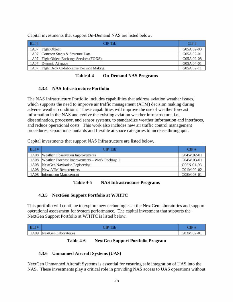
4.3.3 On-Demand NAS Portfolio
On-Demand NAS Information will provide flight planners, air traffic controllers and traffic managers, and flight crews with consistent and complete information related to changes in various areas of the NAS, such as temporary flight restrictions, temporary availability of special activity airspace (this includes military, Temporary Flight Restrictions, other), equipment outages, and runway closures. This portfolio ensures that NAS and other aeronautical information is consistently provided across all NAS applications and locations using common net enabled access to aeronautical and flight information utilizing global standards – Aeronautical Information Exchange Model (AIXM) and Flight Information Exchange Model (FIXM).
BLI # CIP Title CIP #1A05 Automatic Dependent Surveillance-Broadcast (ADS-B) In Applications – Flight Interval
ManagementG01S.02-01
1A05 Modern Procedures G01A.01-011A05 Wake Turbulence Re-Categorization G06M.02-021A05 Separation Automation System Engineering G01A.01-061A05 Closely Spaced Parallel Runway Operations G06N.01-021A05 Concept Development for Integrated NAS Design & Procedures Planning G05A.02-041A05 NextGen Oceanic Capabilities G01A.01-07
BLI # CIP Title CIP #1A06 Surface Tactical Flow G02A.01-011A06 Time Based Flow Management (TBFM) Work Package 4 G02A.01-081A06 Strategic Flow Management Application G05A.01-011A06 Strategic Flow Management Engineering Enhancement (SFMEE) G05A.01-021A06 Advanced Methods G05A.02-02
25
Capital investments that support On-Demand NAS are listed below.
Table 4-4 On-Demand NAS Programs
4.3.4 NAS Infrastructure Portfolio
The NAS Infrastructure Portfolio includes capabilities that address aviation weather issues, which supports the need to improve air traffic management (ATM) decision making during adverse weather conditions. These capabilities will improve the use of weather forecast information in the NAS and evolve the existing aviation weather infrastructure, i.e., dissemination, processor, and sensor systems, to standardize weather information and interfaces, and reduce operational costs. This work also includes new air traffic control management procedures, separation standards and flexible airspace categories to increase throughput. Capital investments that support NAS Infrastructure are listed below.
Table 4-5 NAS Infrastructure Programs
4.3.5 NextGen Support Portfolio at WJHTC
This portfolio will continue to explore new technologies at the NextGen laboratories and support operational assessment for system performance. The capital investment that supports the NextGen Support Portfolio at WJHTC is listed below.
Table 4-6 NextGen Support Portfolio Program
4.3.6 Unmanned Aircraft Systems (UAS)
NextGen Unmanned Aircraft Systems is essential for ensuring safe integration of UAS into the NAS. These investments play a critical role in providing NAS access to UAS operations without
BLI # CIP Title CIP #1A07 Flight Object G05A.02-031A07 Common Status & Structure Data G05A.02-011A07 Flight Object Exchange Services (FOXS) G05A.02-081A07 Dynamic Airspace G05A.04-011A07 Flight Deck Collaborative Decision Making G05A.02-11
BLI # CIP Title CIP #1A08 Weather Observation Improvements G04W.02-011A08 Weather Forecast Improvements – Work Package 1 G04W.03-011A08 NextGen Navigation Engineering G06N.01-031A08 New ATM Requirements G01M.02-021A08 Information Management G05M.03-01
BLI # CIP Title CIP #1A09 NextGen Laboratories G03M.02-01

26
impacting manned aircraft operations and creating disruptions or delays. They will ensure that UAS operations in the NAS will be more efficient and as safe, or safer, than they are today. Capital investments that support Unmanned Aircraft Systems are listed below.
Table 4-7 Unmanned Aircraft Systems (UAS) Programs
4.3.7 Enterprise, Concept Development, Human Factors, & Demonstrations
Portfolio This portfolio will conduct the research needed to determine the viability and benefits of future NAS concepts. It conducts enterprise level activities, including development of concepts across the NAS, human factors analysis of the NextGen operational environment, and demonstrations of proposed NextGen system improvements to ensure operational feasibility and viability with the NAS. Concepts will be researched and assessed to identify research issues, evaluate benefits, reduce risk, and develop preliminary operational requirements and procedures to enhance safety, increase operational efficiency, increase airspace capacity, and expand current capabilities throughout the NAS. Capital investments that support Enterprise, Concept Development, Human Factors, & Demonstrations Program are listed below.
Table 4-8 Enterprise, Concept Development, Human Factors, & Demonstrations
Programs
4.3.8 Performance-Based Navigation & Metroplex Portfolio PBN uses RNAV and Required Navigation Performance (RNP) to improve access and flexibility in the NAS with the goal of providing the most efficient aircraft routes from departure runway to arrival runway with greater precision and accuracy. Progressive stages of PBN capabilities include the safe implementation of more closely spaced flight paths for departure, arrival, and approach and improves the operational efficiency for airports located in Metroplexes.
BLI # CIP Title CIP #1A10 Unmanned Aircraft Systems (UAS) Concept Validation and Requirements Development G01A.05-021A10 Unmanned Aircraft Systems (UAS) Flight Information Management G01A.05-01
BLI # CIP Title CIP #1A11 Enterprise Concept Development G05A.02-101A11 Enterprise Human Factor Development G01M.02-051A11 Stakeholder Demonstrations G08M.01-04

27
Capital investments that support Performance Based Navigation & Metroplex are listed below.
Table 4-9 Performance Based Navigation & Metroplex Programs
4.3.9 System Safety Management Portfolio
System Safety Management is developing data acquisition, storage, analysis, and modeling capabilities to meet the safety analysis needs of NextGen designers, implementers, and safety professionals. These resources will be used to ensure that new capabilities either improve or maintain current safety levels while improving capacity and efficiency in the NAS. Capital investments that support System Safety Management are listed below.
Table 4-10 System Safety Management Programs
4.3.10 Cross Agency NextGen Management
Delivering NextGen is a high priority for the Administration, the Department of Transportation, and the FAA. Its complexity and interdependencies make it the most challenging FAA undertaking to date requiring evaluation of internal processes and internal structures to meet the demands of modernizing the NAS. The NextGen Interagency Planning Office integrates NextGen multi-agency research and development requirements and facilitates the transfer of research between its partner agencies. The capital investment that supports Cross Agency NextGen Management is listed below.
Table 4-11 Cross Agency NextGen Management
BLI # CIP Title CIP #
2B19 NextGen Performance Based Navigation (PBN) – Metroplex Area Navigation (RNAV)/Required Navigation Performance (RNP)
G05N.01-01
2B19 NextGen Distance Measuring Equipment (DME) Support For Performance Based Navigation (PBN) Strategy
G01N.01-02
BLI # CIP Title CIP #3A09 Aviation Safety Information Analysis and Sharing (ASIAS) G07A.02-013A09 Systems Safety Management Transformation (SSMT) G07M.02-01
BLI # CIP Title CIP #4A10 Cross Agency NextGen Management G08M.04-01
28
5 Enterprise Architecture Infrastructure Roadmaps The detailed infrastructure roadmaps in the following subsections are an integral part of the NAS Enterprise Architecture and show the existing systems in the NAS and the planned capital programs for both legacy and NextGen systems. The roadmaps extend beyond the 5-year CIP horizon and show extended timelines with planned or proposed NAS modernization envisioned for the future. Upgrading the sophisticated systems used for air traffic control requires significant engineering development efforts and long range planning to ensure the continued safety and efficiency of the NAS. The roadmaps present an executive level view of the programs and systems that make up the NAS and do not include every aspect of the detailed planning behind them. The timelines are included to show the length of time that existing systems or their replacements will remain in service. This highlights the future plan for these legacy systems that may impact the planning, management, and budgeting of interdependent CIP programs developing new or improved capabilities for their replacement. Many improvements shown in the roadmaps require aviation users to add equipment to their aircraft and adopt new procedures which can alert users to potential changes that may affect their equipment and crew training. The roadmaps included in this plan were current as of January 2017. The roadmaps are updated annually to reflect the results of studies, demonstration projects, and economic analyses related to the programs but are generally stable from year-to-year. To view the most recent version of the Enterprise Architecture Infrastructure Roadmaps see: http://faa.gov/nextgen/delivering/nasea . The infrastructure roadmaps in this section organize the architecture by functional area. The systems shown in light blue on the left side of the diagrams are currently in service. Funding to maintain and operate the in-service systems is provided by the Operations appropriation. Capital investments to upgrade or replace these systems are shown by the program boxes within the roadmap timeline and are funded by the Facilities and Equipment appropriation. The length of each box on the roadmaps reflects the fiscal years that a program has, or is expected to receive funding; legacy programs are shown as gray bars and NextGen are orange. A dotted box means that a program is planned but funding has not yet been identified. Below each roadmap, a brief description is provided for each of the systems shown along the left side of the roadmaps. For each related CIP program requesting funds between FY 2018-2022, a brief summary is provided in this section that includes the purpose of the program, the associated BLI number, CIP title, and CIP number. Full descriptions of the capital programs are provided in Appendix B. The BLI may be used to associate a CIP program shown on the FAA Enterprise Architecture Roadmaps with the funding identified in Section 8, Estimated Funding by BLI. Note that BLIs may include funds that support multiple CIP programs. Figure 5-1 shows and defines the symbols used in the infrastructure roadmaps. The solid red lines indicate the time that systems, or their replacements will remain in operation. The dashed lines indicate that a system is scheduled to be replaced or taken out of service. The end date of operation is indicated with an X. The boxes with names identify programs, functions or systems,
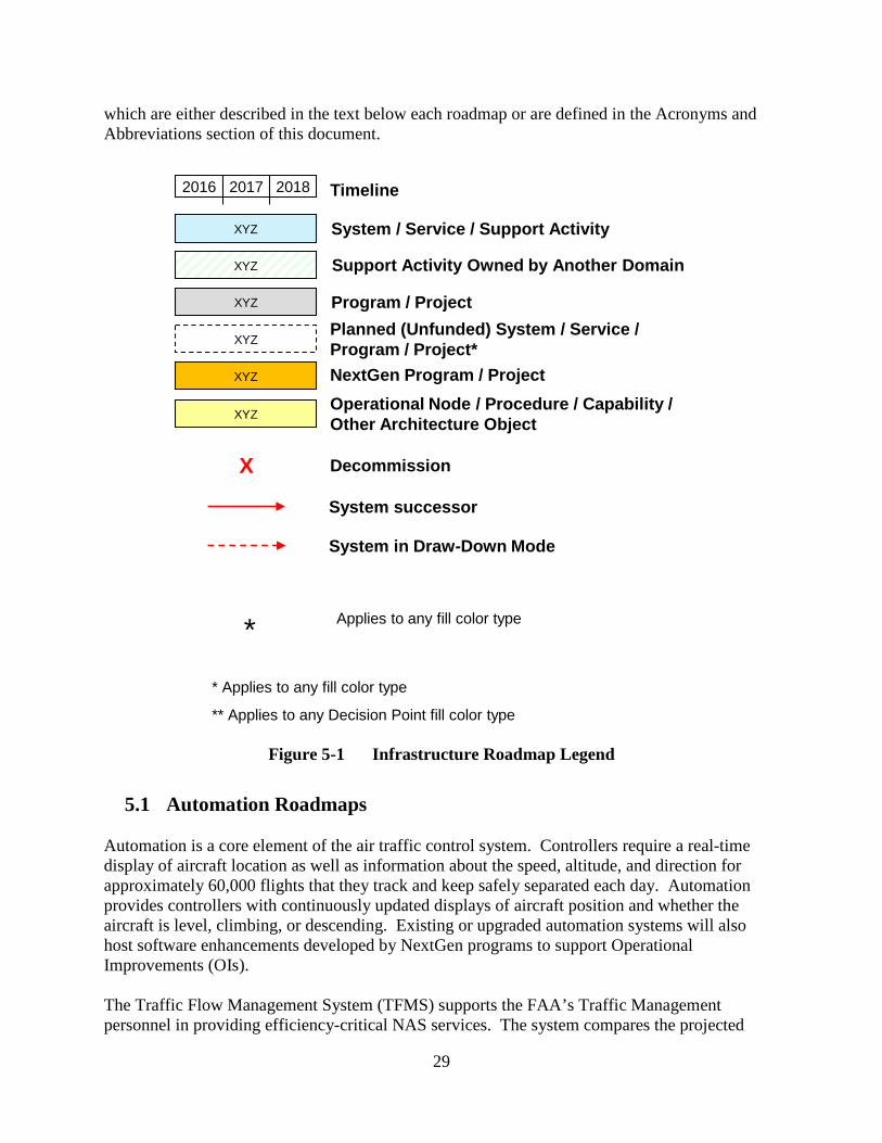
29
which are either described in the text below each roadmap or are defined in the Acronyms and Abbreviations section of this document.
Figure 5-1 Infrastructure Roadmap Legend
5.1 Automation Roadmaps
Automation is a core element of the air traffic control system. Controllers require a real-time display of aircraft location as well as information about the speed, altitude, and direction for approximately 60,000 flights that they track and keep safely separated each day. Automation provides controllers with continuously updated displays of aircraft position and whether the aircraft is level, climbing, or descending. Existing or upgraded automation systems will also host software enhancements developed by NextGen programs to support Operational Improvements (OIs). The Traffic Flow Management System (TFMS) supports the FAA’s Traffic Management personnel in providing efficiency-critical NAS services. The system compares the projected
XYZ System / Service / Support Activity
System successor
System in Draw-Down Mode
Decommission X
Timeline2016 2017 2018
XYZ NextGen Program / Project
* Applies to any fill color type
** Applies to any Decision Point fill color type
XYZ Program / Project
XYZPlanned (Unfunded) System / Service / Program / Project*
XYZOperational Node / Procedure / Capability / Other Architecture Object
XYZ Support Activity Owned by Another Domain
Applies to any fill color type*

30
traffic with the capacity of destination airports to determine if steps need to be taken to manage the flow and prevent delays. Throughout each day, Traffic Managers use the TFMS to maintain near real-time situational awareness and predict areas which may experience congestion due to capacity reductions or an unusual increase in demand. The TFMS is used to facilitate planning teleconferences every two hours to proactively plan impact mitigation strategies between the Air Traffic Control System Command Center (ATCSCC), Traffic Management Units (TMU) at all major Air Traffic Control (ATC) facilities (80 sites), and flight operators. TFMS remote sites are also located at other FAA and Government offices (39). Automation implementation, including the plans to sustain, upgrade, replace or decommission current systems from 2016 through 2030 are shown in the following NAS EA roadmaps:
1. Roadmap 1 (figure 5-2) - Air Traffic Management and Air Traffic Control 2. Roadmap 2 (figure 5-3) - Air Traffic Support and Oceanic Air Traffic Control 3. Roadmap 3 (figure 5-4) - Flight Services and Aeronautical / Information Support
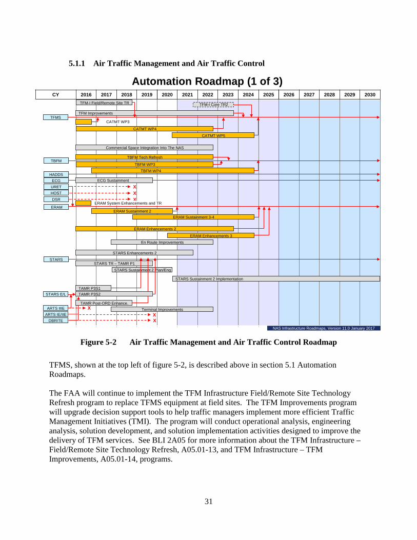
31
5.1.1 Air Traffic Management and Air Traffic Control
Figure 5-2 Air Traffic Management and Air Traffic Control Roadmap
TFMS, shown at the top left of figure 5-2, is described above in section 5.1 Automation Roadmaps. The FAA will continue to implement the TFM Infrastructure Field/Remote Site Technology Refresh program to replace TFMS equipment at field sites. The TFM Improvements program will upgrade decision support tools to help traffic managers implement more efficient Traffic Management Initiatives (TMI). The program will conduct operational analysis, engineering analysis, solution development, and solution implementation activities designed to improve the delivery of TFM services. See BLI 2A05 for more information about the TFM Infrastructure – Field/Remote Site Technology Refresh, A05.01-13, and TFM Infrastructure – TFM Improvements, A05.01-14, programs.
CY 2016 2017 2018 2019 2020 2021 2022 2023 2024 2025 2026 2027 2028 2029 2030
Automation Roadmap (1 of 3)
ERAM Sustainment 2
TBFM WP3
HOSTURET
DSR
ARTS IE/IIE
STARS
ARTS IIIE
TAMR P3S1
ERAM
HADDSECG
TFMS
CATMT WP4
TBFM
DBRITE X
TFM-I Field/Remote Site TR
STARS TR – TAMR P1
XXX
XX
ECG Sustainment
STARS Sustainment 2 Plan/Eng
STARS E/L
TBFM Tech Refresh
TBFM WP4
ERAM Enhancements 2
CATMT WP5
STARS Enhancements 2
TAMR Post-ORD Enhance.
TFM Improvements
TAMR P3S2
Commercial Space Integration Into The NAS
TFM-I Core TR2
ERAM System Enhancements and TR
En Route Improvements
Terminal Improvements
ERAM Sustainment 3-4
CATMT WP3
ERAM Enhancements 3
STARS Sustainment 2 Implementation
NAS Infrastructure Roadmaps, Version 11.0 January 2017
32
The future program, TFM Infrastructure (TFM-I) Core Technology Refresh 2, now called TFMS Modernization Part 2, will modernize remaining TFMS legacy software applications and will increase integration and interoperability by establishing a robust, commercially-available and standards-compliant system. It will also provide a replace-in-kind technology refresh of the hardware providing the central data processing capability for the TFMS. See BLI 2A05 for more information about the TFMS Modernization Part 2, A05.01-15, program. Collaborative Air Traffic Management Technologies (CATMT) Work Packages (WP) are capability enhancements to the TFMS and expand collaboration to individual pilots and improve information exchange between the FAA and airline dispatch offices. Collaboration improves the efficiency of operations by helping operators determine the most efficient way to allocate NAS capacity. See BLI 2A14 for more information about the CATMT – Work Package 4, G05A.05-03, and CATMT – Work Package 5, G05A.05-04, programs. (The NextGen Operational Improvements that these NextGen programs support can be found in Section 4.1.) The Commercial Space Integration into the NAS program will introduce processes and procedures that will allow the FAA to reduce the amount of airspace required to be closed in advance of a mission, effectively respond to off-nominal scenarios in a timelier manner during a mission, and quickly release airspace back to the system as the mission progresses. The program will develop a Space Data Integrator capability to automate the FAA’s current manual process and provide data integration capability to process real-time vehicle and aircraft hazard area data and provide the information to the TFMS and affected facilities. The program is working toward a FID. See BLI 2A22 for more information about the Commercial Space Integration Into The NAS, M55.01-01, program. The Space Integration Enhancements 1 program supports the integration of commercial space into the NAS by focusing on Space Data Integrator improvements as well as the integration of an improved Aircraft Hazard (AHA) generator capability. The improved AHA generator “Hazard Risk Assessment and Management (HRAM)” will be capable of calculating refined AHAs in seconds, rather than minutes. The program is working toward a FID. See BLI 2A22X for more information about the Space Integration Enhancements 1, G01M.03-01, program. The Time Based Flow Management (TBFM) system uses time-based metering to better utilize NAS capacity by improving traffic flow management of aircraft approaching and departing congested airspace and airports. Aircraft using this technique can arrive properly sequenced and spaced to maximize capacity at the nation’s busiest airports. TBFM has been deployed and is operational at 20 Air Route Traffic Control Centers and adapted for most major airports served by these centers. TBFM Technology Refresh program will replace the existing hardware that was deployed in 2012 and 2013 with new hardware in the FY 2021-2022 time frame to support TBFM WP4. The program is working toward a FID. See BLI 2A15 for more information about the TBFM Technology Refresh, G02A.01-07, program. TBFM Work Package 3 will implement additional NextGen concepts, such as optimized descent during time-based metering; Terminal Sequencing and Spacing to provide efficient sequencing
33
and runway assignment and also includes expansion of the Integrated Departure /Arrival Capability to additional locations. See BLI 2A15 for more information about the TBFM Work Package 3, G02A.01-06, program. (The NextGen Operational Improvements that this NextGen program supports can be found in Section 4.1.) TBFM Work Package 4 will build upon existing core TBFM capabilities to increase benefits from time-based metering and enable the expansion of PBN operations across the NAS. Time-based metering through TBFM has provided an average 3-5% increase in throughput at the airports where it is installed. See BLI 1A06 for more information about the TBFM Work Package 4, G02A.01-08, program. (The NextGen Operational Improvements that this NextGen program supports can be found in Section 4.1.) The Host ATM Data Distribution System (HADDS) supplies data to the TFMS discussed above and will remain in operation through the timeframe of the current roadmap (2016-2030). The En Route Communications Gateway (ECG) system is a computer system that formats and conveys critical air traffic data to the En Route Automation Modernization (ERAM) and the Enhanced Backup Surveillance System at the Air Route Traffic Control Centers. The ECG Sustainment program plans, procures, and deploys ECG hardware or software components to maintain a high level of system availability. See BLI 2A02 for more information about the ECG – Sustainment, A01.12-02, program. The ERAM program incorporated three of the en route system component pieces: User request Evaluation Tool (URET); Host Computer; and Display System Replacement (DSR). DSRs are the ATC displays at the en route centers. URET is a conflict-detection tool that automatically detects and advises air traffic controllers of potential conflicts between aircraft or between aircraft and special activity airspace. ERAM became fully operational in 2015 and supports the agency's transition to NextGen. The ERAM system replaced the Host Computer, processes flight and surveillance data, and generates display data for en route air traffic controllers. The ERAM Sustainment 2 and 3 programs will sustain the ability for en route controllers to collectively track up to 1,900 aircraft at a time by updating a subset of ERAM equipment that is in critical need of replacement at the 20 ARTCC. The ERAM Sustainment 3 program is working toward FID. See BLI 2A01 for more information about the ERAM Sustainment 2, G01A.01-10, and ERAM Sustainment 3, G01A.01-11, programs. The ERAM Enhancements 2 and 3 programs will improve the efficiency and effectiveness of en route sector operations by enabling the implementation of NextGen capabilities to support increased efficiency and capacity benefits. ERAM Enhancements 2 program provides software enhancements for the en route sector controller team. These include enhancements to improve conflict probe processing, support for Unmanned Aircraft Systems (UAS), and other improvements. The ERAM Enhancements 3 program provides separation management automation enhancements to assist en route controllers in managing safe aircraft separation in a mixed environment of varying navigation equipment and wake performance capabilities. It will improve trajectory modeling, enhance conflict probe processing and detection, and optimize use of aircraft PBN data. The ERAM Enhancements 3 program is working toward FID. See BLI

34
2A01 for more information about the ERAM Enhancements 2, G01A.01-08, and ERAM Enhancements 3, G01A.01-12, programs. The En Route Improvements program will improve the presentation, access, and use of ERAM and other systems data by air traffic controllers and managers, resulting in more efficient, safer, and cost-effective delivery of en route services. It will conduct operational analysis, engineering analysis, solution development, and solution implementation activities designed to improve the delivery of en route domain services. See BLI 2A21 for more information about the En Route Improvements, A01.16-01, program. The last five systems in figure 5-2 provide ATC automation for terminal airspace. They include the Standard Terminal Automation Replacement System (STARS); The STARS Enhanced Local Integrated Tower Equipment / Local Integrated Tower Equipment (STARS E/L); The Automated Radar Terminal System model IIIE (ARTS IIIE); ARTS 1E/IIE; and Digital Bright Radar Indicator Tower Equipment (DBRITE). STARS and ARTS systems allow TRACON controllers to track aircraft as they transition from en route control to terminal airspace, normally within 60 miles of the destination airport. DBRITE is a tower display that allows tower cab controllers to determine the location of approaching traffic before it becomes visible to them. STARS – Technology Refresh (TAMR Phase 1) program is the technology refresh of STARS automated radar processing and display systems at 48 Terminal Radar Approach Control (TRACON) facilities and their associated Air Traffic Control Towers (ATCTs). The TAMR Phase 1 program will provide hardware updates including new high-resolution Liquid Crystal Display color displays, processors, storage devices, and enhanced memory; and a software update to support NextGen initiatives, and to maintain, correct, or improve system performance, efficiency, safety, and security vulnerabilities. See BLI 2B02 for more information about the STARS – Technology Refresh (TAMR Phase 1), A04.01-01, program. The STARS Sustainment 2 Planning and Engineering will enable the FAA to design and replace key elements of STARS that have reached their end-of-life (EOL) and are no longer compatible with current commercial offerings. STARS Sustainment 2 Implementation program will engineer and deploy additional key elements of STARS that reach EOL and are no longer compatible with current commercial offerings in the FY 2021 time frame. These programs are working towards a FID. See BLI 2B02 for more information about the STARS – Sustainment 2 Planning/Engineering, A04.01-03, and STARS – Sustainment 2 Implementation, A04.01-05, programs. The Terminal Automation Modernization – Replacement (TAMR) – Phase 3, Segment 2 will replace 91 Automated Radar Terminal System (ARTS) IIE systems at TRACONs and their associated ATCTs, and six ARTS IE systems (stand-alone ATCT display systems) with STARS hardware, software, and displays. This Segment will deploy a scaled STARS system, known as STARS Enhanced Local Integrated Tower Equipment (ELITE) to the ARTS IIE facilities; and STARS Remote Towers to the ARTS IE facilities. The STARS automation system is a fully digital system capable of tracking all aircraft within the defined terminal airspace using available FAA and U.S. Department of Defense (DoD) surveillance systems. See BLI 2B03 for more information about the TAMR – Phase 3, Segment 2, A04.07-02, program.

35
The Terminal Automation Modernization – Replacement (TAMR) – Post Operational Readiness Demonstration (ORD) Enhancements program considered requests for operational needs and capabilities that existed in ARTS at the time of transition to STARS at Phase 1 and Phase 3 sites. As requests were identified, validated, prioritized, and approved for implementation, the TAMR Program Office used existing, mature processes for the engineering, design, development, testing, integration and delivery of hardware and software additions to these sites. The Terminal Improvements program will support operational analysis, engineering analysis, solution development, and solution implementation activities designed to improve the delivery of terminal services. The scope of these NAS improvements is limited to operational changes that don’t require significant capital investments, a formal investment decision, or involve significant systems complexity, interdependencies, or NAS operational changes. See BLI 2B04 for more information about the Terminal Improvements, A.04.09-02, program. The STARS Enhancements 2 program is the next useful segment for the STARS platform and will consolidate terminal automation onto a single platform. As envisioned by NextGen, it will implement the capabilities necessary to enable trajectory-based operations in the terminal environment and identify and address outstanding operational needs. The program is working towards a FID. See BLI 2B04 for more information about the STARS – Enhancements 2, A04.08-01, program.

36
5.1.2 Air Traffic Support and Oceanic Air Traffic Control
Figure 5-3 Air Traffic Support and Oceanic Air Traffic Control Roadmap
The first program at the top of figure 5-3, the Air Traffic Support and Oceanic Air Traffic Control Roadmap, is Terminal Flight Data Manager (TFDM) – Core, Segment 1. TFDM will provide tower air traffic controllers and FAA traffic managers with NextGen decision support capabilities that integrate flight, surveillance, and traffic management information to improve air traffic control coordination and decision making. The use of Electronic Flight Data and Strips (EFD/EFS) will allow tower controllers to maintain an integrated view of the air traffic environment, improving their situational awareness of airport operations. TFDM decision support capabilities will promote safe and efficient airport operations in managing airport surface traffic sequencing and scheduling. The implementation plan is based on a two software build approach and deployment of TFDM from FY 2020 to FY2028. See BLI 2B16 for more information about the TFDM – Core, Segment 1, G06A.03-01, program. (The NextGen Operational Improvements that this NextGen program supports can be found in Section 4.1.) The first system on the top left of figure 5-3 is the Departure Spacing Program (DSP) used by tower controllers to optimize taxi and takeoff clearances in order to efficiently use available
CY 2016 2017 2018 2019 2020 2021 2022 2023 2024 2025 2026 2027 2028 2029 2030
ATOP Enhancements WP1
Automation Roadmap (2 of 3)
ATOP
DOTS+
MEARTSFDP2KOFDPS
ATOP Sustainment 2
ATOP Enhancements WP2
FDIO Replacement - SustainmentFDIO
ATOP Oceanic Improvements
X
XERIDS
E-IDS
IDS4 / IDS5
NIDS
ACE-IDS
X
X
Enterprise IDS
TDLS
EFSTSSMA
Tower DCL Services (TDLS) Segment 1
TFDM
DSP XX
XXARMT
TFDM Core Segment 1
TFDM Enhancements and TR
Offshore Automation
IDS-Replacement
IDS-R TR
E-IDS Tech Refresh
NAS Infrastructure Roadmaps, Version 11.0 January 2017
37
runway and airspace capacity. The Surface Movement Advisor (SMA) provides the status of aircraft moving from the gates to the runways and improves taxiing efficiency. The Electronic Flight Strip Transfer System (EFSTS) is a system to transfer flight information to towers and TRACONs electronically rather than by paper. The Airport Resource Management Tool (ARMT) provides an assessment of available airport capacity. The Tower Data Link Services (TDLS) provides data link of the as-filed flight plan (called Pre-Departure Clearance (PDC)) through Airline operators to pilots preparing to depart an airport. See Communications Roadmap 5, section 5.2, for a description of the Data Communications Segment 1 Phase 1 program. The Enterprise Information Display System (E–IDS) program will manage the upgrade or replacement of systems included in the IDS replacement program. These systems provide controllers, front line managers, traffic managers, and maintenance personnel with the full range of information including aeronautical, weather, and administrative information affecting all phases of flight to assist in efficiently managing airspace. The program is working towards a FID. See BLI 2B13 for more information about the E–IDS, A03.05-03, program. The Integrated Display Systems model 4 (IDS-4), IDS model 5 (IDS-5), and NAS IDS (NIDS) provide rapid retrieval and display of a wide range of weather, operational support, and administrative information for air traffic controllers and other users in the terminal environment. The Integrated Display Systems (IDS) Replacement program is replacing the IDS-4 with a state-of-the-art system comprised mainly of Commercial-Off-The-Shelf (COTS) components; the last will be in 2017. The Automated Surface Observing System (ASOS) Controller Equipment-Information Display System (ACE-IDS) displays weather information collected by ASOS to tower controllers. These services will begin a transition to E-IDS starting in FY 2022. The En Route Information Display System (ERIDS) is an information display system that provides access to aeronautical data including weather, airspace charts, ATC procedures, Notices to Airmen (NOTAM), and pilot reports (PIREPS). The ERIDS will begin a transition to E-IDS starting in FY 2023. The Flight Data Input/Output (FDIO) system interfaces to several En Route automation systems and provides standardized flight plan data, weather information, safety related data, and Wake Re-categorization to Air Traffic Controllers located at approximately 690 remote sites. The FDIO – Sustainment program replaces end-of-life/obsolete FDIO equipment with fully compatible Commercial Off-The-Shelf (COTS) and modified COTS equipment. To maintain system availability, the program replaces individual components as they reach the end of their service life based upon a 5 year replacement cycle. See BLI 2B04 for more information about the FDIO – Sustainment, A01.11-01, program. The Dynamic Ocean Tracking System plus (DOTS+) system uses weather information to determine the most fuel-efficient routes based on wind velocity and direction. It will continue in
38
operation through the timeframe of the roadmap. The three oceanic automation systems, Offshore Flight Data Processing System (OFDPS), Flight Data Processing 2000 (FDP2K), and the Microprocessor En route Automated Radar Tracking System (Micro-EARTS), process flight data regarding the position of aircraft on oceanic and offshore flights to aid controllers in separating flights in FAA controlled airspace. The Offshore Automation program will perform service analysis and concept requirements definition for four sites in the NAS that have unique automation platforms not found at CONUS or Oceanic sites. These include the Anchorage Air Route Traffic Control Center, the Honolulu Control Facility, the Guam Combined Control Facility (CCF), and the San Juan CCF. All four have the same Radar Data Processor and Microprocessor En Route Automated Radar Tracking System; the Flight Data Processor varies by facility. Replacing these with existing NAS systems will improve interoperability and reduce costs by standardizing training, maintenance, and development efforts across the platforms. The program is working towards a FID. See BLI 2A19 for more information about the Offshore Automation, A38.01-01, program. The Advanced Technologies and Oceanic Procedures (ATOP) program updated procedures and modernized the oceanic automation systems located at the Oakland, New York, and Anchorage ARTCCs. ATOP fully integrates flight and radar data processing, detects conflicts between aircraft, provides data link and surveillance capabilities, and automates previously manual processes for oceanic air traffic control. The ATOP – Sustainment 2 program will replace the hardware and operating system, and integrate the new technology with the baseline ATOP applications. The ATOP program reduces maintenance and logistics costs and supports incorporation of software changes and new capabilities to support future NextGen, Surveillance and Broadcast Services, and other NAS improvements. A FID was achieved in February 2016. See BLI 2A09 for more information about the ATOP – Sustainment 2, A10.03-01. The ATOP – Oceanic Improvements program will support operational analysis, engineering analysis, solution development, and solution implementation activities designed to improve the delivery of oceanic domain services. This includes improving the flexibility, reliability, and efficiency of oceanic air traffic control by providing enhancements to more frequently accommodate user preferred flight trajectories and altitude changes increasing the likelihood of on-time arrivals. See BLI 2A09 for more information about the ATOP – Oceanic Improvements, A10.03-03. The ATOP – Enhancements (Work Package 1) program is addressing the operational shortfalls of the current oceanic system as the FAA moves forward with NextGen and other NAS upgrades. The program is working towards a FID. See BLI 2A09 for more information about the ATOP Enhancements (Work Package 1), A10.03-02, programs. A future program, ATOP Enhancements (Work Package 2), will continue to address operational shortfall of the oceanic systems beyond FY 2021.
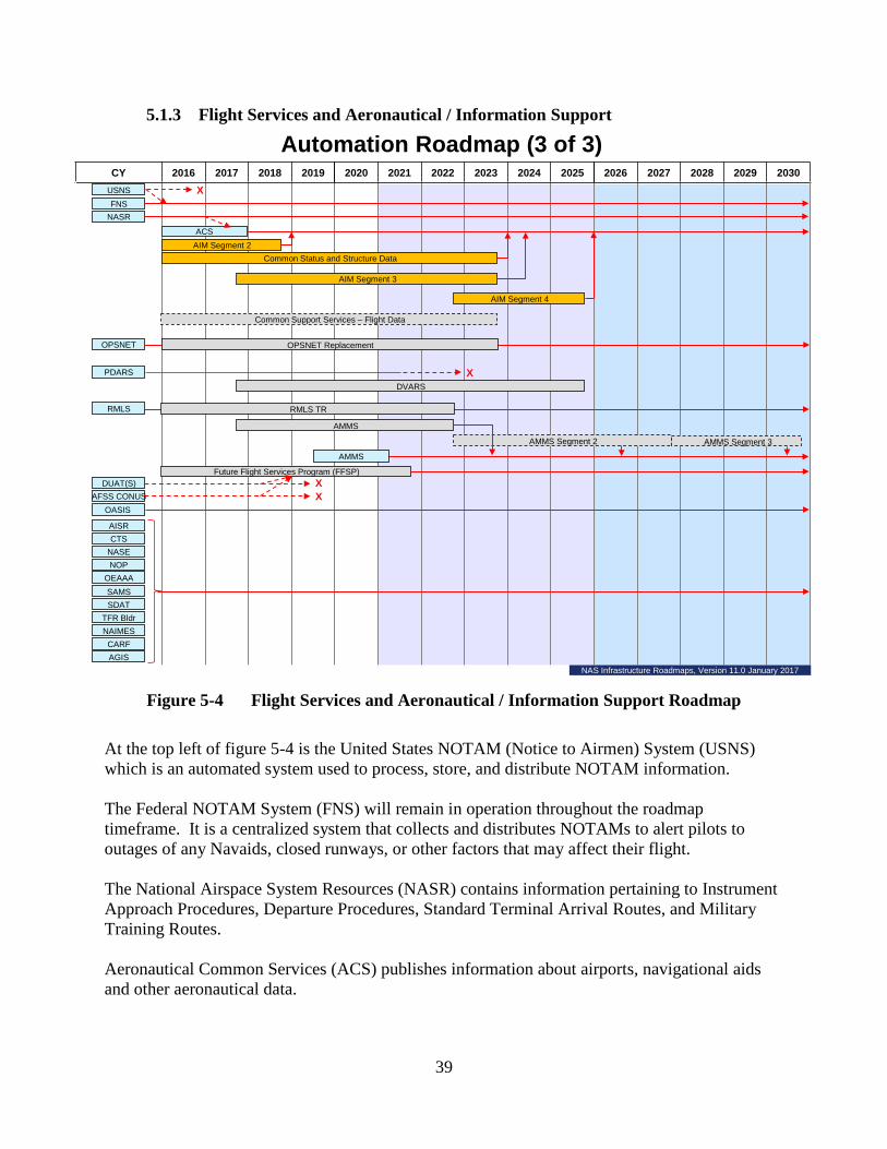
39
5.1.3 Flight Services and Aeronautical / Information Support
Figure 5-4 Flight Services and Aeronautical / Information Support Roadmap
At the top left of figure 5-4 is the United States NOTAM (Notice to Airmen) System (USNS) which is an automated system used to process, store, and distribute NOTAM information. The Federal NOTAM System (FNS) will remain in operation throughout the roadmap timeframe. It is a centralized system that collects and distributes NOTAMs to alert pilots to outages of any Navaids, closed runways, or other factors that may affect their flight. The National Airspace System Resources (NASR) contains information pertaining to Instrument Approach Procedures, Departure Procedures, Standard Terminal Arrival Routes, and Military Training Routes. Aeronautical Common Services (ACS) publishes information about airports, navigational aids and other aeronautical data.
CY 2016 2017 2018 2019 2020 2021 2022 2023 2024 2025 2026 2027 2028 2029 2030
Common Status and Structure Data
Automation Roadmap (3 of 3)
AMMS
Future Flight Services Program (FFSP)DUAT(S)
OASIS AFSS CONUS
RMLS
AMMS Segment 2
RMLS TR
AMMS Segment 3
ACSAIM Segment 2
FNS
AIM Segment 3
AIM Segment 4
NASE
CARFAGIS
NOP
PDARS
CTS
NAIMES
NASR
TFR Bldr
AISR
OEAAA
SDAT
USNS
SAMS
X
AMMS
XX
Common Support Services – Flight Data
OPSNET OPSNET Replacement
XDVARS
NAS Infrastructure Roadmaps, Version 11.0 January 2017
40
The Common Status & Structure Data (CSSD) program will establish the requirements and information flows for the collection, management, and maintenance of aeronautical information in a digital format for machine to machine exchange. The common data and information services and integration activities enable improved flight planning and pilot briefing services; increased on-demand NAS operational performance information; and better airspace management using timely schedule information and a common awareness of Special Activity Airspace (SAA) status across the NAS. To support NextGen capabilities, this program enables the FAA to improve situational awareness through better access to aeronautical information and a common language. See BLI 1A07 for more information about the CSSD program, G05A.02-01, program. The Aeronautical Information Management (AIM) Modernization Segment 2 program will provide aviation users with digital aeronautical information that conforms to international standards and supports NextGen objectives. This program builds on pre-implementation efforts performed in the NextGen Common Status and Structure Data program, G05A.02-01, to baseline and implement suitably mature AIM technologies and tools for Aeronautical Information exchange. See BLI 4A09 for more information about the AIM Modernization Segment 2, G05A.02-05, program. The Aeronautical Information Management (AIM) Modernization Segment 3 program will modernize and expand on the ACS enterprise service and initial Special Activity Airspace (SAA) and Geographic Information Service (GIS) capabilities developed by AIM Modernization Segment 2. Segment 3 will add performance capability, increase integration with NAS automation, and integrate static aeronautical information with operational data feeds providing updates on the activation status of SAA and active runway/airport configuration data from the authoritative source. The CSSD program is working towards a FID for AIMM Segment 3. See BLI 4A09 for more information about the AIM Modernization Segment 3, G05A.02-06, program. Future modernization under AIM Modernization Segment 4 is currently planned to begin in FY 2023. The Common Support Services – Flight Data (CSS-FD) program will provide single operator interface to NAS for flight planning and filing and improve the exchange of early intent, i.e., pre-departure data, NAS constraint checking, and flight plan submission. This will allow the airspace users to more effectively plan flight operations. This work is being funded under the Flight Object program G05A.02-03. The Operations Network (OPSNET) is the official FAA system for collecting and reporting flight operations count and delay metrics. The OPSNET system measures the number of delays attributable by cause and includes weather, air traffic volume, equipment status, and runway conditions. The OPSNET Replacement program will expand the collection and recording of delay causes to improve reporting and provide a system that limits manual data entry and automates compilation of operational data received from FAA automation systems. The program is working towards a FID. See BLI 1A01 for more information about the OPSNET Replacement, A37.01-01, program.

41
The Performance Data Analysis and Reporting System (PDARS) is a fully integrated performance measurement tool designed to help the FAA improve the NAS by tracking the daily operations of the ATC system and its environmental impact. The Data, Visualization, Analysis and Reporting System (DVARS) program will eventually replace PDARS and provide data and analyses on NAS operations to FAA executives, Air Traffic Managers, and Air Traffic Operations personnel to help them identify deficiencies and develop proposals to improve NAS performance. The program is working toward a Final Investment Decision (FID). See BLI 2E11 for more information about the DVARS, M08.28-05, program. The Remote Maintenance Logging System (RMLS) allows systems maintenance staff to monitor equipment performance electronically from a central location and is used for generating, quantifying, analyzing, measuring, and reporting maintenance information. RMLS improves the effectiveness of Tech Ops maintenance processes and practices and oversees the entire event management life cycle, from generation of the initial event through assignment, updates, and event closure. The RMLS Technology Refresh program will extend the service life of RMLS hardware and software located at the National Operations Control Center (NOCC), Atlantic Operations Control Center (AOCC), Mid-States Operations Control Center (MOCC), Pacific Operations Control Center (POCC), Southern California TRACON (SCT), the William J. Hughes Technical Center (WJHTC), ARTCCs, and the Combined Control Facility (CCF) in Hawaii. See BLI 2B14 for more information about the RMLS – Technology Refresh, M07.04-02, program. The Automated Maintenance Management System (AMMS) will allow for the interfacing of maintenance systems through a Service-Oriented Architecture (SOA) environment utilizing System Wide Information Management (SWIM) to create an enterprise infrastructure for sharing data between dispersed maintenance systems. The ability to efficiently manage the maintenance of FAA’s equipment and systems is critical to the operation of the NAS. AMMS will develop common enterprise data services for maintenance data; implement data standards for the exchange of data between services, systems, and equipment; and deliver advanced automated maintenance tools to improve data integrity and increased situational awareness to support predictive rather than periodic maintenance. The program is working towards a FID. See BLI 2B14 for more information about the AMMS, M07.05-01, program. The Automated Flight Service Station Continental United States (AFSS CONUS), Direct User Access Terminal System (DUATS), and Operational and Supportability Implementation System (OASIS) provide aeronautical and weather data to support flight services. Flight services include flight planning and pilot weather briefings which are primarily used by General Aviation (GA) pilots. Contractor flight service personnel using the AFSS CONUS provide flight services in the lower 48 States, Hawaii and Puerto Rico. The DUATS is a web-based service that allows pilots to access weather and aeronautical data for self-briefings and to file flight plans. The OASIS automation system is used at the Flight Service Stations in Alaska by FAA flight service specialists to provide flight services to GA pilots.
42
The Future Flight Service Program (FFSP) will subsume AFSS and DUATS scope, seeking to enhance GA and NAS users’ safety awareness by providing more accurate and efficient updates to changing weather conditions and allowing pilots to make better decisions on avoiding hazardous weather. FFSP will provide flight services to the GA community within the Continental US, Puerto Rico, and Hawaii. FFSP expands the web portion of flight services and seeks to reduce or eliminate obsolete or redundant services and activities provided by other FAA service organizations. The program is working towards a FID. See BLI 2C02 for more information about the FFSP, A34.01-01, program. The last 12 systems shown on Figure 5-4 are expected to continue in operation through the current roadmap. A brief description of the service or capability provided by each of these systems for airports, airspace, and navigation facilities is provided below. Aeronautical Information System Replacement (AISR) distributes information on weather, flight plans, NOTAMS, Pilot Reports, and other NAS status items to FAA facilities, DoD, and pilots. Coded Time Source (CTS) provides the official source of time that synchronizes the information flows in the air traffic control equipment. NAS Adaptation Services Environment (NASE) contains detailed information about the airspace, geography, equipment, and procedures required to make each ATC system work properly. National Offload Program (NOP) allows FAA to download radar information from en route automation systems for analysis and review. Obstruction Evaluation/Airport Airspace Analysis (OEAAA) contains data about obstructions around airports that present a hazard for aircraft taking off and landing. Special Airspace Management System (SAMS) informs controllers when airspace ordinarily reserved for military use is available for civilian use. Sector Design and Analysis Tool (SDAT) is a visualization and analysis tool used to evaluate the impact on controller workload when sector and route changes are being considered during major airspace redesign efforts. Temporary Flight Restriction Builder (TFR Bldr) is an automated system for establishing temporary flight restrictions that prohibit aircraft from flying over areas where special events such as the Super Bowl are being held. NAS Aeronautical Information Management Enterprise System (NAIMES) consists of a suite of NAS safety/mission critical systems and services that directly support the collection, validation, management, and dissemination of aeronautical information in the NAS. Central Altitude Reservation Function (CARF) is a system used by military and civilian pilots to reserve altitudes for their planned flights.

43
Airport Geographic Information System (AGIS) collects, stores, and disseminates geospatial features and attributes associated with the physical infrastructure of the airport. It is used to develop airport modernization plans and is necessary for maintaining existing and developing new approach and departure procedures.
5.2 Communication Roadmaps Communication between pilots and controllers is an essential element of air traffic control and is primarily accomplished using voice radios. To ensure controllers can stay in contact with pilots, remotely located radio sites are used to provide continuous coverage. Controllers use electronic links through ground-based telecommunication lines to activate remote site radios that carry voice transmissions between air traffic controls and pilots. If ground links are unavailable, satellite communication links can be used. In the future, data link may be used for most routine communications. Backup systems are also available to ensure uninterrupted communication should a primary system fail. Communication system implementation is broken down into five different NAS EA roadmaps:
1. Roadmap 1 (figure 5-5) - Telecom and Other Communications 2. Roadmap 2 (figure 5-6) - Voice Switches and Recorders 3. Roadmap 3 (figure 5-7) - Air-to-Ground Voice and Oceanic Communications 4. Roadmap 4 (figure 5-8) - Air-to-Ground Data Communications 5. Roadmap 5 (figure 5-9) - Messaging Infrastructure

44
5.2.1 Telecom and Other Communications
Figure 5-5 Telecom and Other Communications Roadmap
Radio Communications Link (RCL) equipment is an analog microwave system originally, created to transmit radar data from remote radar sites to FAA air traffic control facilities. These systems were linked in a national network to transmit operational and administrative information to and from air traffic control facilities. RCL equipment is now obsolete and its functions are transitioning to the FAA Telecommunications Infrastructure (FTI) contract. The Data Multiplexing Network (DMN) and the National Airspace Data Interchange Network – Package Switching Network (NADIN PSN), transmit flight plans and other important aeronautical information to air traffic facilities. The functions of DMN and NADIN PSN are also transitioning to the FTI network. The FTI contract provides telecommunications services that are designed, engineered, and provisioned to meet FAA-specific availability, latency, and security requirements. FTI also provides enterprise messaging services based upon service-oriented architecture technologies
CY 2016 2017 2018 2019 2020 2021 2022 2023 2024 2025 2026 2027 2028 2029 2030
Communications Roadmap (1 of 5)
FTI
ANICS
LDRCL
RCL
BWM
DMN
NADIN MSN
X
X
Alaskan Satellite Telecom Infrastructure (ASTI)
X
ATIS
RCOM
NADIN PSN X
RCOM Command and Control Communications
X
X
FTI-2
IESP
Oth
er C
omm
unic
atio
nsTe
leco
m
ECG ECG Sustainment
FTI-2
ASTI
X
TDM-to-IP Migration
NAS Infrastructure Roadmaps, Version 10.6 January 2017
45
and specialized infrastructure services such as a domain name service, network time protocol service, and security gateway services. The Time-Division Multiplexing to Internet Protocol (TDM-to-IP) Migration program oversees the investment portfolio for TDM-to-IP migration and is conducting the systems interface development work in order to modernize NAS systems to be IP-compatible. Major U.S. telecommunications carriers plan to discontinue TDM-based services as early as calendar year 2020. More than 90% of the current FAA services obtained under the FTI contract are TDM-based. See BLI 2E12 for more information about the TDM-to-IP Migration, M56.01-01, program. FTI-2, the successor program to FTI, will provide all of the capabilities currently available under the existing FTI contract plus the next generation of telecommunications, messaging, and infrastructure services required by FAA programs during the FTI-2 program life cycle. FTI-2 will address the challenges associated with the orderly transition of TDM-based telecommunication services (nearly 90%) to IP. FTI-2 is planned to continue beyond 2030 and is working towards a Final Investment Decision (FID). See BLI 2E10 for more information about the FTI-2, C26.01-02, program. The Low Density Radio Communication Link (LDRCL) is a legacy analog microwave system providing a similar function as RCL (see above) and is being phased out. The Bandwidth Manager (BWM) improves efficiency of information flow on the microwave network. It will not be needed when microwave links are no longer used. The Alaska National Airspace System Interfacility Communications System (ANICS) consists of ground stations that send and receive data from communications satellites to connect the operational facilities in Alaska. Because there are far fewer ground telecommunications connections in Alaska, a satellite system is used to ensure that important air traffic information is reliably transmitted between small and large facilities. ANICS provides 90% of the communications for En Route, Terminal, and Oceanic air traffic control, and Flight Services in Alaska. The ASTI program will modernize the ANICS to support routine, essential, and critical NAS Systems & Services. The newly approved ASTI Enhancement program will establish yearly software/hardware releases to ensure that components fielded under ASTI remain operational through the system lifecycle. See BLI 2E05 for more information about the ASTI, C17.02-01, and the ASTI Enhancement, C17.02-02, programs. The NADIN Message Switching Network (MSN) complies with international standards for transmitting flight plans between service providers and remains available for that purpose. The Integrated Enterprise Service Platform (IESP) is a shared computing infrastructure that provides a common set of server and network hardware for the hosting of multiple NAS services. It leverages virtualization technology to maximize the return on investment for hardware procurements, and provides value added configuration management and high availability

46
services. IESP uses an enterprise level Simple Network Management Protocol system which is capable of providing monitoring services for external NAS systems. NAS Recovery Communications (RCOM) program enables the FAA Administrator and senior staff to directly manage the NAS during local, regional, and national emergencies if normal communications with facilities are disrupted. RCOM’s Command and Control Communications (C3) system elements provide and enhance communication capabilities through a variety of fixed-position, portable, and transportable emergency communications systems to support crisis management and enable the FAA and other Federal agencies to exchange both classified and unclassified information to protect national security during an emergency. See BLI 3A03 for more information about the RCOM, C18.00-00, program. The Automated Terminal Information System (ATIS) broadcasts weather and other pertinent information to pilots as they approach an airport. ATIS functions will be maintained during the entire timeframe of the roadmap. See Automation Roadmap 1section 5.1.1 and BLI 2A02 for more information about the En Route Communications Gateway (ECG) – Sustainment, A01.12-02, program.
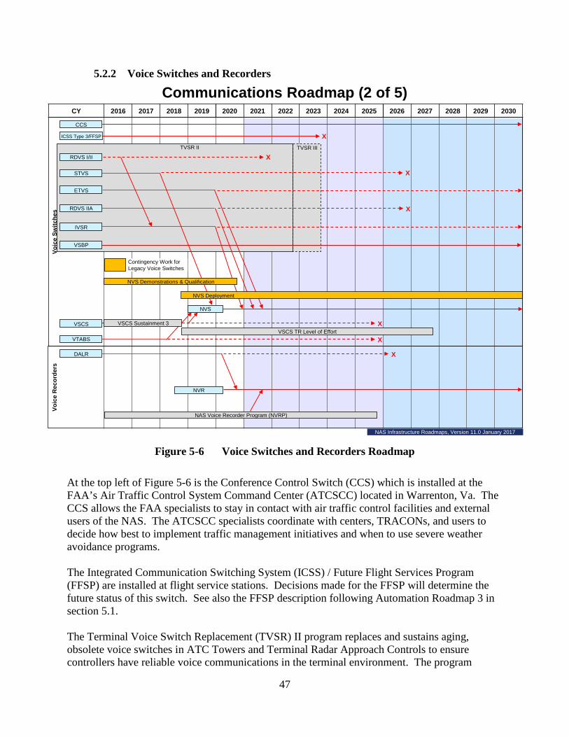
47
5.2.2 Voice Switches and Recorders
Figure 5-6 Voice Switches and Recorders Roadmap
At the top left of Figure 5-6 is the Conference Control Switch (CCS) which is installed at the FAA’s Air Traffic Control System Command Center (ATCSCC) located in Warrenton, Va. The CCS allows the FAA specialists to stay in contact with air traffic control facilities and external users of the NAS. The ATCSCC specialists coordinate with centers, TRACONs, and users to decide how best to implement traffic management initiatives and when to use severe weather avoidance programs. The Integrated Communication Switching System (ICSS) / Future Flight Services Program (FFSP) are installed at flight service stations. Decisions made for the FFSP will determine the future status of this switch. See also the FFSP description following Automation Roadmap 3 in section 5.1. The Terminal Voice Switch Replacement (TVSR) II program replaces and sustains aging, obsolete voice switches in ATC Towers and Terminal Radar Approach Controls to ensure controllers have reliable voice communications in the terminal environment. The program
CY 2016 2017 2018 2019 2020 2021 2022 2023 2024 2025 2026 2027 2028 2029 2030
Contingency Work for Legacy Voice Switches
TVSR IIITVSR II
Communications Roadmap (2 of 5)
Voic
e R
ecor
ders
CCS
VSCS
RDVS I/II
ETVS
RDVS IIA
STVS
IVSR
X
X
X
DALR
X
VSBP
VTABS
ICSS Type 3/FFSP
NVS
NVR
X
NAS Voice Recorder Program (NVRP)
NVS Deployment
NVS Demonstrations & Qualification
VSCS Sustainment 3VSCS TR Level of Effort
X
X
NAS Infrastructure Roadmaps, Version 11.0 January 2017
Voic
e Sw
itche
s

48
consists of several multiyear equipment contracts for voice switches including Small Tower Voice Switches (STVS), Enhanced Terminal Voice Switches (ETVS), Rapid Deployment Voice Switches (RDVS), Voice Switch By Pass (VSBP) system, and Interim Voice Switch Replacement (IVSR). This program also establishes contract vehicles with the flexibility for FAA to procure voice switch equipment for new or modernized terminal facilities. Terminal voice switching systems direct and control voice communications so that the controller can communicate with another controller position either within or at another air traffic control facility, or with a properly equipped aircraft. The VSBP is a backup voice switch that terminal controllers can use to stay in communication with pilots if there is a failure in the primary voice switch. See BLI 2B07 for more information about the TVSR II, C05.02-00, program. In FY 2023 a future program, TVSR III, will be established to refurbish and replace terminal voice switches that are not replaced under the NAS Voice System (NVS) program. The NVS program will replace legacy voice switches at both En Route and Terminal facilities and will be implemented in two segments; Demonstration & Qualification, and Deployment. The NVS – Demonstration & Qualification program received FID for NAS qualification from the Joint Resources Council (JRC) in September 2014. The program will return to the JRC in FY 2019 to request FID approval for deployment of NVS to operational facilities beyond the key sites. See BLI 2B12 for more information about the NVS – Demonstration & Qualification, G03C.01-01, and NVS – Deployment, G03C.01-02, programs. The Voice Switching and Control System (VSCS) allow en route controllers to communicate with pilots, other controllers, other air traffic facilities, and commercial telephone contacts. VSCS Training and Backup Switches (VTABS) are independent voice communication switches for en route training and serve as hot backup voice communications switches for critical VSCS air-to-ground and ground-to-ground communications. VTABS provides air traffic controllers and pilots with a path for voice communications in the event that VSCS is unavailable. VSCS and VTABS must be available at all ARTCCs until the systems are replaced by the NVS. VSCS Training and Backup Switch (VTABS) can maintain critical Air-to-Ground (A/G) and ground-to-ground communications if the main communications system becomes inoperable as a result of a power outage, a catastrophic system failure, or during system maintenance or upgrade activities. VTABS also will allow air traffic controllers to train on equipment virtually identical to VSCS. The VSCS –Technology Refresh – Phase 3 program will replace and upgrade hardware and software components for the voice switching systems in all 21 en route air traffic control centers and at the testing and training systems located at the William J. Hughes Technical Center and the FAA Academy. The VSCS – Technology Refresh – Level of Effort program will maintain ongoing Diminishing Manufacturing Sources and Material Shortages analysis, conduct program management activities, and provide engineering support. Depending on continued engineering analyses, potential technology refresh activities under the Level of Effort program may include VTABS Subsystem refresh, VSCS Control Subsystem refresh and Position Equipment Test Set refresh. VSCS Technology Refresh Level of Effort will be a stand-alone effort starting FY 2019 and will continue to sustain VSCS/VTABS until fully replaced by NVS. See BLI 2A08 for more

49
information about the VSCS –Technology Refresh – Phase 3, C01.02-04, and VSCS – Technology Refresh – Level of Effort, C01.02-05, programs. The Digital Audio Legal Recorder (DALR) is the voice recorder that provides a legally accepted recording capability for conversations between air traffic controllers, pilots, and ground-based air traffic facilities in all ATC domains. These recordings are used in the investigation of accidents and incidents and for routine evaluation of ATC operations. The NAS Voice Recorder Program (NVRP) will replace digital voice recorders to comply with new requirements in the Air Traffic Organization (ATO) safety orders. The program is working towards a FID. See BLI 2B17 for more information about the NVRP, C23.02-01, program.
5.2.3 Air-to-Ground Voice and Oceanic Communications
Figure 5-7 Air-to-Ground Voice and Oceanic Communications Roadmap
At the top left of Figure 5-7 is Multimode Digital Radios (MDR) Very High Frequency (VHF) Ground Radios which are used by controllers to communicate with the pilots. MDRs can operate both the existing analog 25 kHz band width voice mode protocol for channel separation, or they can operate in the more efficient 8.33 kHz band width voice mode currently used in Europe. The MDRs support Voice over Internet Protocol (VoIP) and meet the requirements of the NextGen Data Communications and NVS programs.
CY 2016 2017 2018 2019 2020 2021 2022 2023 2024 2025 2026 2027 2028 2029 2030
CFE – Expansion
RCE Sustainment
NEXCOM Seg. 2 Phase 1 NEXCOM Seg.2 Phase 2
Communications Roadmap (3 of 5)
A/G
Voi
ce
UHF GroundRadios
VHF GroundRadios
ETR UHF/VHFTransceivers
VHFHandheld
BUEC
MDR VHFGround Radios
Interference DetectionLocation
And Mitigation
Oceanic HFVoice Service
OceanicData Link
Service
Oce
anic
A
ir-G
roun
d
RCF
Airport Cable Loop
RCE
Airport Cable Loop Systems Sustained Support
CFE – RFI Elimination TR
NAS Infrastructure Roadmaps, Version 11.0 January 2017
50
Very High Frequency (VHF) and Ultra High Frequency (UHF) Ground Radios utilize the 25 kHz band width to allow controllers to communicate with civilian and military aircraft, respectively. The Emergency Transmitter Replacement (ETR) UHF/VHF Transceivers provide emergency and backup service when primary radios are not working. VHF Handheld Transceivers are used by maintenance technicians so they can communicate with each other and with ATC tower personnel. The Next Generation VHF and UHF Air/Ground (A/G) Communications (NEXCOM) program replaces the aging and obsolete analog radios with digital radios that allow direct voice communication with pilots. The NEXCOM Segment 1a program completed replacement of all 25,000 en route radios with MDRs in FY 2013, at both primary and back up communications (BUEC) sites. NEXCOM Segment 2 program will ultimately replace a total of 35,000 primary and back up VHF and UHF radios at terminal and flight service facilities. The Segment 2 program is segmented into two phases; Phase 1 will replace a total of 15,000 radios from FY 2009 through FY 2018; and Phase 2 will replace a total of 20,000 radios from FY 2019 through FY 2026. The Phase 2 program also replaces Emergency Transceivers and is working towards a FID. See BLI 2A10 for more information about the NEXCOM – Segment 2 Phase 1, C21.02-01, and NEXCOM – Segment 2 Phase 2, C21.02-02, programs. The Backup Emergency Communication (BUEC) is a facility which consists of radios and equipment installed at remote sites that backup the primary radios installed at Remote Communication Air Ground facilities, all of which are used by Air Route Traffic Control Center (ARTCC) controllers to communicate with pilots. The Radio Control Equipment (RCE) allows voice and data communications between the air traffic controller and pilots using remotely located VHF/UHF radios accessible via the RCE and interconnection telecommunications networks. The RCE – Sustainment program replaces obsolete radio signaling and control equipment which controllers use to select a remote radio channel. The RCE program improves reliability by replacing older non-supported tone control equipment providing more functionality and improving operational performance. See BLI 2A06 for more information about the RCE – Sustainment, C04.01-01, program. Airport Cable Loop are on-airport copper-based, FAA-owned signal/control cable lines that feed airport surveillance radar, air/ground communications, and landing systems data and information to the tower, and operational and maintenance information to FAA-staffed facilities. The Airport Cable Loop Sustained Support program replaces obsolete underground telecommunications cable infrastructure systems that have deteriorated and are vulnerable to failure which could cause flight delays related to outages. Where cost effective, the program will install a fiber-optic cable in a ring configuration to provide redundancy and communications diversity. See BLI 2E04 for more information about the Airport Cable Loop Sustained Support, F10.00-00, program.

51
The Communications Facilities Enhancement (CFE) – Expansion program provides new, relocated, or upgraded Remote Communication Facilities (RCF) to enhance the A/G communications between air traffic control and the aircraft when there are gaps in coverage or new routes are adopted. The program also provides various upgrades to RCFs, including building and tower grounding lightning protection, and replaces cables from the equipment to the antennas when necessary to improve radio equipment performance. See BLI 2A06 for more information about the CFE – Expansion program, C06.01-01, program. The Interference Detection, Location and Mitigation program investigates occurrences of non-FAA transmitters interfering with FAA radios and navigation systems, locates the source, and ensures that they no longer interfere with FAA controlled frequencies. The FAA has specially equipped vehicles that detect and locate the sources of interference. The Oceanic High Frequency (HF) Voice Service allows controllers and pilots to communicate over oceanic airspace once the aircraft is out of range from ground-based VHF radios. The Oceanic Satellite Data Link Services is used by equipped aircraft and relies on communications satellites to transfer messages to and from aircraft flying over the oceans. Once aircraft are beyond the range of radar, pilots must report their position using either HF Voice Service or satellite-based Oceanic Data Link Service when they arrive at predetermined waypoints.
5.2.4 Air-to-Ground Data Communications
CY 2016 2017 2018 2019 2020 2021 2022 2023 2024 2025 2026 2027 2028 2029 2030
Communications Roadmap (4 of 5)
A/G
Dat
a C
omm
unic
atio
ns
Data Comm Segment 1 Phase 1 (Tower Service)
B2Equipage: Airborne
Data Comm Segment 2 - Advanced Services
TDLS V11
Tower Enhancements
En Route Enhancements
FANS 1/A and VDL2 Equipage: Airborne
Logon/Protocol Gateway (PGW) (ERAM EAXX)
FANS
Data Comm Segment 1 Phase 2 (Initial En Route Services)
Tower DCL Services (TDLS V12)
Data Comm DCIS Network Services (DCNS)
Data Comm Segment 3
ERAM R3
TDLS Enhancements
ERAM Enhancements
Data Comm ATN Gateway
Data Comm ATN Baseline 2 APP
Data Comm Segment 1 Phase 2 (Full En Route Services)
Data Comm DCIS Network Services (DCNS) FutureData Communications Network Service VDL2: GroundDCNS
ERAM Enhancements
NAS Infrastructure Roadmaps, Version 11.0 January 2017

52
Figure 5-8 Air-to-Ground Data Communications Roadmap The Future Air Navigation System (FANS) is an avionics system that provides data link communication between the pilot and the Air Traffic Controller using the Aircraft Communications Addressing and Reporting System network. ERAM R3, the En Route Automation Modernization system became fully operational in 2015 and supports the agency's transition to NextGen. The Tower Data Link Services (TDLS) provides data link of the as-filed flight plan (called Pre-Departure Clearance (PDC)) through Airline operators to pilots preparing to depart an airport. The Data Comm program will provide data communications services between pilots and air traffic controllers. Data Comm will provide a link between ground automation and flight deck avionics for ATC clearances, instructions, traffic flow management, flight crew requests and reports. Data Comm is critical to the success of NextGen operational improvements by providing communication infrastructure enhancements. These improvements to the NAS will be delivered by Data Comm in three segments. Segment 1 will deliver in two phases the initial set of data communications services integrated with automation support tools to provide NAS benefits and lay the foundation for a data-driven NAS. Segment 1 Phase 1 (S1P1) will deploy the Controller-Pilot Data Link Communications (CPDLC) Departure Clearance (DCL) in the Tower domain and the Data Comm Network Services (DCNS) infrastructure to provide the air/ground communications between the controllers and pilots. Segment 1 Phase 2 (S1P2) will deliver CPDLC data communications services to the En Route domain. The Data Comm En Route services will contribute to a reduction in flight delays, more efficient routes for aircraft resulting in increased operational efficiency, enhanced safety all while reducing operational costs for airspace users. The Data Comm Integrated Services (DCIS) program will continue to provide and expand the VHF Data Link (VDL) Mode 2 air ground network service that provides connectivity between the controllers and the cockpit. The DCNS includes operations and maintenance, monitoring and control, and certification suite activities and supports both surface and en route operations. See BLI 2A18 for more information about the Data Communications programs that include:
• Data Communications – Segment 1 Phase 1, G01C.01-05 • Data Communications – Segment 1 Phase 2 Initial En Route Services, G01C.01-06 • Data Communications – S1P1 and S1P2 Data Comm Integrated Services (DCIS)
Network Services, G01C.01-07 • Data Communications – Segment 1 Phase 1 & Phase 2 Data Comm Integrated Services
(DCIS) Network Services Future, G01C.01-11 In the future, Data Comm Segment 2 and Segment 3 will further build upon CPDLC DCL and En Route services by supporting the delivery of services to enable advanced NextGen operations not possible using voice communications, such as Four Dimensional Trajectory Data Link, Advanced Interval Management, Tailored Arrivals, Digital Taxi, and dynamic Required
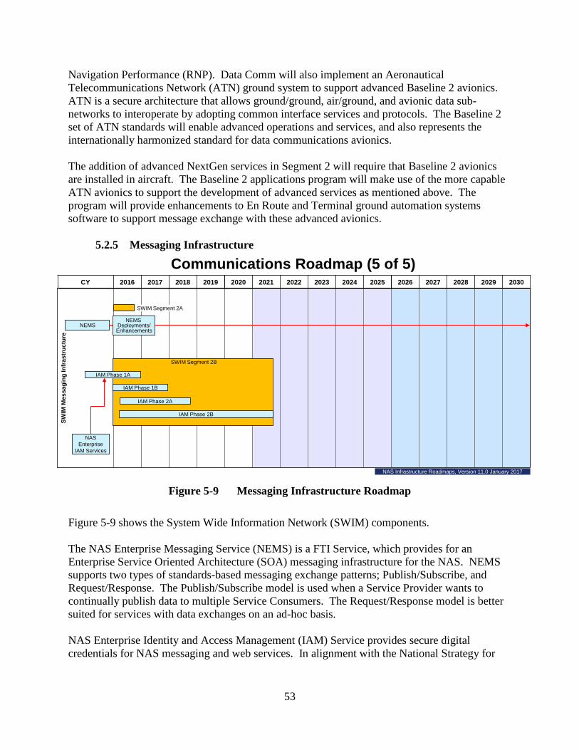
53
Navigation Performance (RNP). Data Comm will also implement an Aeronautical Telecommunications Network (ATN) ground system to support advanced Baseline 2 avionics. ATN is a secure architecture that allows ground/ground, air/ground, and avionic data sub-networks to interoperate by adopting common interface services and protocols. The Baseline 2 set of ATN standards will enable advanced operations and services, and also represents the internationally harmonized standard for data communications avionics. The addition of advanced NextGen services in Segment 2 will require that Baseline 2 avionics are installed in aircraft. The Baseline 2 applications program will make use of the more capable ATN avionics to support the development of advanced services as mentioned above. The program will provide enhancements to En Route and Terminal ground automation systems software to support message exchange with these advanced avionics.
5.2.5 Messaging Infrastructure
Figure 5-9 Messaging Infrastructure Roadmap
Figure 5-9 shows the System Wide Information Network (SWIM) components. The NAS Enterprise Messaging Service (NEMS) is a FTI Service, which provides for an Enterprise Service Oriented Architecture (SOA) messaging infrastructure for the NAS. NEMS supports two types of standards-based messaging exchange patterns; Publish/Subscribe, and Request/Response. The Publish/Subscribe model is used when a Service Provider wants to continually publish data to multiple Service Consumers. The Request/Response model is better suited for services with data exchanges on an ad-hoc basis. NAS Enterprise Identity and Access Management (IAM) Service provides secure digital credentials for NAS messaging and web services. In alignment with the National Strategy for
CY 2016 2017 2018 2019 2020 2021 2022 2023 2024 2025 2026 2027 2028 2029 2030
Communications Roadmap (5 of 5)
NEMS
SWIM
Mes
sagi
ng In
fras
truc
ture
SWIM Segment 2B
NAS Enterprise
IAM Services
IAM Phase 1A
IAM Phase 2A
IAM Phase 1B
IAM Phase 2B
NEMS Deployments/
Enhancements
SWIM Segment 2A
NAS Infrastructure Roadmaps, Version 11.0 January 2017
54
Trusted Identities in Cyberspace, IAM provides authentication and authorization services that ensure secure information sharing with FAA partners. SWIM’s enterprise infrastructure enables systems to publish information of interest to NAS users; request and receive information from other NAS services; and support NAS security requirements. Segment 2B provides Governance to NAS programs to ensure services are SWIM compliant and meet all FAA SOA standards. Segment 2B will implement Identity and Access Management Phase 2, Enterprise Service Monitoring Phase 2 and 3, SWIM Terminal Data Distribution System Phase 2, and NAS Common Reference. A new program SWIM Segment 2C – NAS Enterprise Messaging Service (NEMS) Technology Refresh Infrastructure and 3rd Party Provider Services includes additional infrastructure and capabilities to strengthen the overall NAS information system security posture. Plans for SWIM Segment 2C include technology refresh of existing NAS Enterprise Messaging Service (NEMS) infrastructure such as NEMS nodes, Local Load Balancer, Global Load Balancer, and Solace boxes. The program also plans to complete additional NEMS Infrastructure upgrades at eight sites to expand capacity. Swim 2C will also add 3rd Party Provider Services to support 500+ Tier 2 external NEMS consumers. See BLI 2A11 for more information about the SWIM – Segment 2B, G05C.01-08, and SWIM Segment 2C – NAS Enterprise Messaging Service (NEMS) Technology Refresh Infrastructure and 3rd Party Provider Services, G05C.01-10, programs.
5.3 Surveillance Roadmaps To provide separation services to aircraft, air traffic controllers must have an accurate display of all aircraft under their control. Surveillance data is provided by the following technologies:
• Primary radar – the radar beam is bounced off the aircraft and reflected back to the radar receiver.
• Secondary radar – a reply is generated by the aircraft transponder and sent back to the radar in response to a secondary radar signal.
• Multilateration – multiple ground sensors receive aircraft electronic signals and triangulate this information to determine aircraft position.
• ADS-B – the aircraft determines its location using a GPS receiver or other navigation equipment and broadcasts that information to an ADS-B ground station. The ground station relays the position information to automation systems which process the data and send it to controller displays. ADS-B Out equipage has been mandated in most controlled airspace by January 1, 2020; where transponders are required today.
En route and terminal facilities normally use Secondary radars (either the Air Traffic Control Beacon Interrogators (ATCBI) or the Mode Select (Mode S)) for traffic separation. Using ATCBI or Mode S enhances the controller’s ability to separate traffic because speed and altitude information supplement the position display for each aircraft.

55
Surveillance systems are shown in three different roadmaps: 1. Roadmap 1 (figure 5-10) - En Route Surveillance 2. Roadmap 2 (figure 5-11) - Terminal Surveillance 3. Roadmap 3 (figure 5-12) - Surface, Approach and Cross Domain Surveillance
5.3.1 En Route Surveillance
Figure 5-10 En Route Surveillance Roadmap
The Common ARSR (CARSR) and the Air Route Surveillance Radars model-4 (ARSR-4) are long-range primary radars that are used to support defense of the national airspace and provide surveillance data to air traffic control facilities for the continental United States, Guam, and Hawaii. The DoD and Department of Homeland Security will continue to fund system upgrades of the CARSRs and ARSR-4s through the time frame of the roadmap due to national security concerns. The Common Digitizers (CD-2) that convert analog radar information to a digital format will not be needed after programs to convert radar information to internet protocol are completed.
CY 2016 2017 2018 2019 2020 2021 2022 2023 2024 2025 2026 2027 2028 2029 2030
En R
oute
Surveillance Roadmap (1 of 3)
CD-2
ARSR-4
Common ARSR
X
Mode S SLEP Phase 2MODE S
ATCBI-6
WAM
ATCBI-6 TR
DoD/DHS funded/FAA maintained
DoD/DHS funded/FAA maintained
NBSC
SENSRSENSR
X
X
X
Mode S SLEP Phase 3
NAS Infrastructure Roadmaps, Version 11.0 January 2017
ASR-9 / Mode S SLEP Ph. 3 Plan.

56
The Mode Select (Mode S) uses selective beacon detection technology to provide target data and are co-located with Airport Surveillance Radar Model 9 (ASR-9), (ASR-8), or Common Air Route Surveillance Radar (CARSR). The Mode S and co-located primary radars provide beacon reports and correlated radar as digital formatted messages and analog video tailored for automation and display systems at TRACON and ARTCC facilities, the U.S. Department of Defense (DoD), and other users. The Mode S Service Life Extension Program (SLEP) Phase 2 program will implement modifications to the Mode S system to sustain secondary aircraft surveillance in terminal and en route airspace. The Mode S program is conducting an additional High Gain Open Planner Array Antenna Assessment to determine the requirements for new antenna procurements and/or the number of antennas that can be refurbished to sustain Mode S through 2026 The Mode S SLEP Phase 3 program identified 11 critical Lowest Replaceable Units (LRUs) modifications needed to address obsolescence, end of service life, and diminishing manufacturing sources in order to sustain Mode S operations until 2035. The Phase 3 program is working towards FID. See BLI 2B15 for more information about the Mode S SLEP – Phase 2, S03.01-08, and Mode S SLEP – Phase 3, S03.01-13, programs. The Next Generation Backup Surveillance Capability (NBSC) will provide a replacement for existing surveillance systems including ATCBI-5, ATCBI-6, Mode-S and ASR-11 Monopulse Secondary Surveillance Radar systems. NBSC will support cooperative target acquisition and maintain continuity of operations if ADS-B outages should occur. NBSC has been subsumed by a cross-agency program titled Spectrum Efficient National Surveillance Radar (SENSR) that is being initiated to make available the band 1300-1350 MHZ for reallocation to shared Federal and non-Federal use through updated radar technology. The SENSR Spectrum Pipeline Plan has been approved and the Government is receiving funds from the Spectrum Relocation Fund to conduct a two-phased feasibility assessment of the proposed spectrum reallocation. The feasibility assessment is expected to be completed by 2021.
• Phase I – Defining: The first phase would occur over approximately two years and will focus on requirements and concept development as well as documenting expected costs and information for all impacted systems.
• Phase II – Refining: The second phase will focus on maturing the selected alternative into a viable and well-planned investment program ready for Solution Implementation.
In the event SENSR program is determined to be infeasible, the FAA must provide a cost-effective replacement for legacy cooperative surveillance service as a backup for ADS-B in en route and select high density terminal environments. In this case the NBSC and Next Generation Surveillance and Weather Radar Capability (NSWRC) investment analysis activities will be reinitiated to address their shortfalls. The ATCBI-6 provides air traffic controllers with a selective interrogation capability that significantly improves the accuracy of aircraft position and altitude data provided to ATC automation systems. Additionally, the ATCBI-6, in conjunction with a co-located primary Long
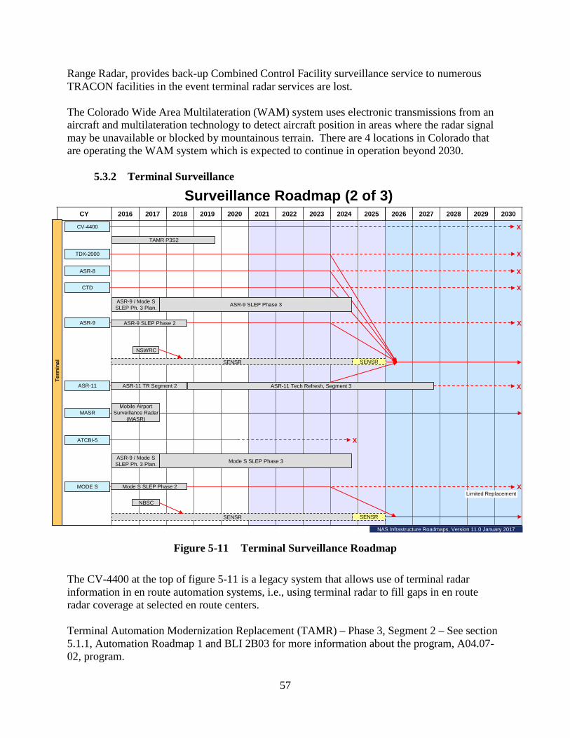
57
Range Radar, provides back-up Combined Control Facility surveillance service to numerous TRACON facilities in the event terminal radar services are lost. The Colorado Wide Area Multilateration (WAM) system uses electronic transmissions from an aircraft and multilateration technology to detect aircraft position in areas where the radar signal may be unavailable or blocked by mountainous terrain. There are 4 locations in Colorado that are operating the WAM system which is expected to continue in operation beyond 2030.
5.3.2 Terminal Surveillance
Figure 5-11 Terminal Surveillance Roadmap
The CV-4400 at the top of figure 5-11 is a legacy system that allows use of terminal radar information in en route automation systems, i.e., using terminal radar to fill gaps in en route radar coverage at selected en route centers. Terminal Automation Modernization Replacement (TAMR) – Phase 3, Segment 2 – See section 5.1.1, Automation Roadmap 1 and BLI 2B03 for more information about the program, A04.07-02, program.
CY 2016 2017 2018 2019 2020 2021 2022 2023 2024 2025 2026 2027 2028 2029 2030
ASR-8
Term
inal
Mode S SLEP Phase 2
ASR-11 TR Segment 2
ASR-9 SLEP Phase 2
X
ASR-9
ASR-11
ATCBI-5
MODE SLimited Replacement
NSWRC
CTD
TAMR P3S2
Surveillance Roadmap (2 of 3)
MASRMobile Airport
Surveillance Radar (MASR)
ASR-11 Tech Refresh, Segment 3
CV-4400
TDX-2000
NBSC
SENSRSENSR
X
X
X
X
X
X
X
SENSRSENSR
ASR-9 SLEP Phase 3
Mode S SLEP Phase 3ASR-9 / Mode S SLEP Ph. 3 Plan.
NAS Infrastructure Roadmaps, Version 11.0 January 2017
ASR-9 / Mode S SLEP Ph. 3 Plan.

58
The TDX-2000 is a legacy system that digitizes the output of analog radars, such as an ASR-8, for use by more modern digital automation systems such as STARS. The ASR-8 is a primary radar system that requires a Common Terminal Digitizer (CTD) be installed to convert analog outputs to digital inputs needed by STARS. As more of the remaining ARTS automation systems are replaced by STARS additional CTDs will be needed. The ASR-9 is a primary radar that tracks aircraft and provides those tracks, as well as six-level weather intensity information, to terminal automation systems so it can be displayed on the controller’s screen. The ASR-9 also provides data to the Airport Movement Area Safety System (AMASS) and to the Airport Surface Detection Equipment – model X (ASDE-X) to aid in the prevention of accidents resulting from runway incursions. The ASR-9 SLEP Phase 2 program will implement modifications to the ASR-9 system to sustain primary radar in terminal airspace. The program will procure Digital Remote Surveillance Communication Interface Processor Replacement systems, Transmitter Backplanes, and Radar Data Access Point, and replenishment of depot inventory of critical components. The ASR-9 SLEP Phase 3 program replaces or upgrades obsolete ASR-9 hardware and software to ensure the continued operation of the radar system. This is an ongoing program that is accomplished in phases to address obsolescence and supportability issues. The phase 3 program is working towards s FID. See BLI 2B09 for information about the ASR-9 SLEP Phase 2, S03.01-09, and ASR-9 SLEP – Phase 3, S03.01-12, programs. The Next Generation Surveillance and Weather Radar Capability (NSWRC) program will provide a cost-effective replacement for several models of ASR and the Terminal Doppler Weather Radars (TDWR) for terminal aircraft surveillance and weather detection. The program will address all existing and emerging primary radar and weather requirements. As shown on the roadmap, the alternative to NSWRC for these requirements will be SENSR if it is formally approved and funded. For more information see the description for SENSR under Surveillance Roadmap 1 in section 5.3.1 En Route Surveillance. The Airport Surveillance Radar Model 11 (ASR-11) is an integrated primary and secondary radar providing six-level weather intensity information to terminal ATC automation systems. The ASR-11 has replaced several of the radars that were not replaced by the ASR-9. The ASR-11 Technology Refresh Segment 2 program replaces and upgrades obsolete Commercial-Off-The-Shelf (COTS) hardware and software to ensure the continued, reliable, and cost effective operation of the ASR-11 radar system in the NAS. The Segment 2 program will address shortfalls identified in the Shortfall Analysis Report including Site Control Data Interface /Operator Maintenance Terminal obsolescence and Uninterruptible Power Supply capacitor at end of life expectancy. ASR-11 Technology Refresh Segment 3 will address parts obsolescence, operational performance deficiencies, and other areas requiring technology refresh. The segment 3 program is working towards a FID. Future ASR-11 Technology

59
Refreshes are dependent on decisions for NSWRC and SENSR. See BLI 2B10 for more information about the ASR-11 – Technology Refresh, Segment 2, S03.02-05, and ASR-11 – Technology Refresh, Segment 3, S03.02-07, programs. The Mobile Airport Surveillance Radar (MASR) is a terminal surveillance radar capability that can be moved from site to site to support radar relocations, temporary planned outages to accommodate installation of upgrades to an existing radar, and emergency operations when existing systems are damaged. MASR capability is planned to continue beyond the time frame of the roadmap. The ATCBI-5 is a secondary surveillance radar and has been operational for more than 25 years. It provides aircraft identification, altitude, airspeed and direction to terminal ATC systems. It will be phased out by 2024. See Surveillance Roadmap 1 in section 5.3.1 and BLI 2B15 for information about the Mode S SLEP Phase 2, S03.01-08, and Mode S SLEP Phase 3, S03.01-13, programs. See Surveillance Roadmap 1 in section 5.3.1 for information about NBSC and SENSR.

60
5.3.3 Surface, Approach and Cross Domain Surveillance
Figure 5-12 Surface, Approach and Cross Domain Surveillance Roadmap
The Runway Status Lights (RWSL) system, see top left of figure 5-12, integrates runway lighting equipment with approach and surface surveillance systems to provide a visual signal to pilots and vehicle operators indicating when it is unsafe to enter/cross or begin takeoff on the runway. The system is fully automated based on inputs from surface and terminal surveillance systems. In August and December 2016, the JRC authorized adding all three prototype systems at Boston, Dallas Fort Worth, and San Diego airports back into the baseline. A total of 19 RWSL systems are planned to be operational by FY 2018. See BLI 2B11 for more information about the RWSL – Implementation – Phase 1, S11.01-02, program. The RWSL Technology Refresh & Disposition program, now called RWSL Sustainment, will assess the need to replace and upgrade obsolete COTS hardware and software to ensure the continued reliable and cost effective operation of the system through its designated lifecycle. The RWSL was procured in late 2008, fielded between 2009 and 2018, and is intended to remain
CY 2016 2017 2018 2019 2020 2021 2022 2023 2024 2025 2026 2027 2028 2029 2030
ADS-B Future Segments
ASDE-X TR& Disposition
Surf
ace
And
Appr
oach
Cro
ss-D
omai
n
Surveillance Roadmap (3 of 3)
X
PRM E-SCAN
ASDE-X
ASDE-3/AMASS
ASSC
ADS-B
FIS-B
ADS-B Baseline Services & Applications
Reduced Oceanic Separation - Advanced Surveillance Enhanced Procedural Separation
ADS-B In Applications Flight Interval Management
ADS-B Sustain Leased Services
ASDE-3 Service Sustainment
SFO
ATL, CLE, PHL, STL
ADS-B Services & Baselines
ADS-B In ApplicationsADS-B Baseline Services Future Segments
RWSL Runway Status Lights (RWSL) – Implementation
Runway Status Lights (RWSL) Tech Refresh and Disposition
RWSL – Prototype Sustainment
ADS-B Sustain Leased Services (FY21-Out)
XAMASS
TIS-B
ADS-R
ADS-B Sustain / Relocate (Gulf of Mexico)
NAS Infrastructure Roadmaps, Version 10.6 January 2017

61
operational until replacement begins in 2026. The program is working towards a FID. See BLI 2B11 for more information about the RWSL – Sustainment, S11.01-04, program. The electronic scan (E-SCAN) version of Precision Runway Monitor (PRM) is used to monitor the safety of aircraft conducting side-by-side simultaneous approaches to closely spaced parallel runways during Instrument Flight Rules (IFR) conditions. It achieves rapid update by moving the beam electronically rather than relying on turning the antenna. It is a secondary rapid update radar that provides the precision that controllers need to ensure that two aircraft maintain safe clearance between them while approaching closely spaced runways. The FAA Flight Standards organization has determined that required runway separation requirements can be reduced which eliminated the need for PRM at Atlanta (ATL). The PRM at San Francisco (SFO) will be sustained utilizing assets from the ATL PRM which will not be replaced. Airport Surface Detection Equipment Model-X (ASDE-X) enables air traffic controllers to track surface movement of aircraft and vehicles. ASDE-X Safety Logic enhances the situational awareness for air traffic controllers by using surveillance information from ASDE-X to determine if the current and/or projected positions and movement characteristics of tracked aircraft/vehicles present a potential collision situation. Visual and audible alerts are provided to the air traffic controllers when the safety logic predicts a collision. The Airport Surface Detection Equipment Model 3 (ASDE-3) is a primary radar system that provides a display of aircraft and ground vehicles in the airport operating areas (runways and taxiways). The Airport Movement Area Safety System (AMASS) is an automation system that utilizes position information from the ASDE-3 system and terminal radars to provide an automatic visual and audio alert to controllers when it detects potential collisions between aircraft or aircraft and vehicles on or near the airport runways. Implemented within the ADS-B NAS Wide Implementation – Baseline Services & Applications program, the Airport Surface Surveillance Capability (ASSC) is a surface multilateration system that receives inputs from multilateration sensors, ADS-B, and Airport Surveillance Radar/Mode Select (ASR/Mode S) terminal radars. Using fused target data, ASSC enhances situational awareness for tower controllers by providing in near real-time for display, the position of all transponder-equipped aircraft and ADS-B equipped ground vehicles on the airport surface movement area, and aircraft flying within five miles of the airport. Automatic Dependent Surveillance – Broadcast (ADS-B) is an advanced surveillance technology that provides highly accurate and more comprehensive surveillance information and is an enabling technology for NextGen. Aircraft position is determined using the Global Navigation Satellite Service (GNSS), and/or an internal inertial navigational reference system, or other navigation aids. The aircraft’s ADS-B equipment processes this position information, along with other flight parameters to be broadcast on the order of once a second to airborne and ground-based ADS-B receivers. This information is used to display the aircraft’s position on en route and terminal automation systems. ADS-B NAS Wide Implementation – Baseline Services & Applications program ensures continuation of the FAA subscription for ADS-B Baseline Services delivered by the prime
62
contractor utilizing contractor owned and operated ADS-B infrastructure and service volumes already in place in the NAS. Subscription fees support the operation of the system, necessary upgrades, and eventual modernization. The program also provides Wide-area Multilateration (WAM) surveillance service capability providing aircraft location information to the automation systems. These services allow controllers to provide separation services at airports in Colorado and North Carolina. Eight airports in the NAS will receive Airport Surface Surveillance Capability (ASSC), which is a surface multilateration system that receives inputs from cooperative and non-cooperative sensors. See BLI 2A12 for more information about the ADS-B NAS Wide Implementation – Baseline Services & Applications (Service Volume), G02S.03-01, program. The ADS-B Sustain Leased Services (FY21-Out) program will continue to provide leased ADS-B services for FY 2021 and beyond. The program plans to introduce a new scope to Baseline Services & Applications by implementing a surveillance backup strategy, new mitigations for spectrum congestion, and re-competing service contracts. The program is working towards a FID. See BLI 2A12 for more information about the ADS-B – Sustain Leased Services (FY21-out), G02S.03-06, program. The Gulf of Mexico (GOM) implementation of Air Traffic Control (ATC) services provides ADS-B surveillance data for aircraft operating in a large area without access to traditional radar coverage. In addition to the ADS-B surveillance facilities, voice communications and weather services are maintained to support ATC Instrument Flight Rule requirements. Aircraft utilizing these services include high altitude commercial aircraft transiting the GOM and low-altitude helicopters providing transportation to the multiple energy platforms operating throughout the GOM. The ADS-B Sustain/Relocate (Gulf of Mexico Platform) program will sustain Air Traffic Services by relocating this equipment to other energy platforms when existing platforms shut down operations. See BLI 2A12 for additional information about the ADS-B NAS Wide Implementation – Sustain/Relocate (Gulf of Mexico Platform), G02S.05-01, program. ADS-B In Applications – Flight Interval Management (IM) consists of a set of ground and flight-deck capabilities and procedures that are used in combination by air traffic controllers and flight crews to more efficiently and precisely manage spacing between aircraft. An air traffic controller can issue an IM clearance that allows flight crews to manage spacing through speed adjustments generated by onboard IM avionics until reaching a planned termination point. IM operations require new flight-deck functions implemented in Flight Interval Management avionics to provide speed guidance to a flight crew to achieve and maintain a relative spacing interval from another aircraft. See BLI 1A05 for more information about the ADS-B In Application - Flight Interval Management, G01S.02-01, program. The ADS-B NAS Wide Implementation – Future Segments program will develop Advanced-Interval Management (A-IM) that supports IM arrivals, approach, and cruise operations, and single runway and dependent runway operations. Pre-implementation activities for these future concepts will be conducted under G01S.02-01. The Reduced Oceanic Separation (ROS) – Advanced Surveillance Enhanced Procedural Separation (ASEPS) program will reexamine current limitations to reducing oceanic separation
63
standards by evaluating improved surveillance capabilities including Space-Based Automatic Dependent Surveillance – Broadcast (ADS-B) and enhanced Automatic Dependent Surveillance – Contract (ADS-C) with a faster update rate than available today. This investment will increase the precision of information used for aircraft separation resulting in safer and more efficient operations. The program is working towards a FID. See BLI 2A20 for more information about the ROS – ASEPS, G02S.04-01, program. Traffic Information Services – Broadcast (TIS-B) is a service that provides ADS-B equipped aircraft with surveillance data about both ADS-B and non-ADS-B equipped aircraft, providing a more complete “picture” of nearby air traffic. Flight Information Services – Broadcast (FIS-B) services provide ground-to-air broadcast of non-air traffic control advisory information which provides users valuable, near real-time information to operate safely and efficiently. FIS-B products include graphical and textual weather reports and forecasts, Special Use Airspace Information, Notices to Airmen, and other aeronautical information. Automatic Dependent Surveillance – Rebroadcast (ADS-R) translates and uplinks ADS-B messages received from aircraft with data links on different frequencies making it possible for each aircraft and vehicle to receive the information being transmitted by the other.
5.4 Navigation Roadmaps Navigation aids (Navaids) can be electronic or visual. En route and terminal electronic aids have traditionally been ground-based radio transmitters that emit signals that allow pilots with aircraft equipped with related avionics to determine the direction and/or distance from the Navaids. The ground-based system commonly used for en route navigation is the Very High Frequency Omni-directional Range with Distance Measuring Equipment (VOR with DME). Aircraft equipped with GPS navigation systems are now able to navigate departure to destination routes without the ground-based Navaids. Visual Navaids are ground-based lighting systems that show pilots the path they need to follow during approach and landing. Navaids also have an important role in guiding pilots to a safe landing in low visibility conditions. They support two types of approaches — precision and non-precision. Instrument Landing Systems (ILS) are used for precision approaches and allow pilots to descend to lower minimum altitudes than are possible with non-precision approaches. Localizer Performance with Vertical Guidance (LPV) is a high precision GPS/WAAS instrument approach procedure with a decision height of 200 feet; similar to the ILS Category I. The minimum altitude, also called the decision height, is the lowest an aircraft can descend before committing to land; the pilot must be able to see the runway at that altitude before descending further. Non-precision approaches use Navaids (other than ILS) and usually only provide lateral guidance, not vertical guidance.

64
Navigational aid programs are portrayed in two different roadmaps: 1. Roadmap 1 (figure 5-13) - Precision Approach & Safety and Enhancements 2. Roadmap 2 (figure 5-14) - Infrastructure and En Route/Terminal/Non-Precision
Approach
5.4.1 Precision Approach & Safety and Enhancements
Figure 5-13 Precision Approach & Safety and Enhancements Roadmap
At the top of Figure 5-13 are programs that support the continued operation of existing systems. See the Navigation Roadmap 2 in section 5.4.2 and BLI 2D07 for more information about Visual Navaids for New Qualifiers, N04.01-00. Approach Lighting Systems (ALS) (I, II, III) helps the pilot see the end of the runway and transition from instrument to visual flight for landing before reaching runway minimums. Navaids – Sustain, Replace, Relocate sustains and/or replaces ALS and Instrument Landing Systems (ILS) at sites where there is a high risk for failure of these systems and where failure would increase the visibility required to land. The ALS include Medium Intensity Approach
CY 2016 2017 2018 2019 2020 2021 2022 2023 2024 2025 2026 2027 2028 2029 2030
Navigation Roadmap (1 of 2)
ILS (I)
SBAS / LPV
ALS (I)
RVR
LP DME
MB
ILS (II / III)
ALS (II / III)
ELVO
Saf
ety
and
Enh
ance
men
ts
CA
T I o
r Equ
ival
ent
CA
T II
/ III
Pre
cisi
on A
ppro
ach
Approach Lighting System Impr (ALSIP) Continuation (Includes ALS I & ALS II/III)
RVR- Replacement/Establishment (Includes CAT I & CAT II/III)
Visual Navaids for New Qualifiers (Includes REILs & CAST PAPIs)
Navaids-Sustain, Replace, Relocate
Sustain Distance Measuring Equipment (Includes LP DME & HP DME)
Enhanced Low Visibility Operations
Phase 2
Instrument Landing Systems (ILS) (Includes CAT I & CAT II/III)
CA
T I /
II /
III
Wide Area Augmentation System (WAAS) – Ph. 4 Seg. 1
Wide Area Augmentation System (WAAS) – Ph. 4 Seg. 2
RSA Runway Safety Area -Navigation Mitigation
WAAS Ph. 4 Seg. 1 –Sustain Leased Services
NAS Infrastructure Roadmaps, Version 11.0 January 2017
65
Lighting System with Runway Alignment Indicator Lights (MALSR) for Category I approaches and High Intensity Approach Lighting System with Sequenced Flashing Lights (ALSF-2) for Category II/III approaches. See BLI 2D09 for more information about the Navaids – Sustain, Replace, Relocate, N04.04-00, program. The Approach Lighting System Improvement Program (ALSIP) Continuation program improves the safety of ALSs built before 1975 to meet current standards by replacing rigid structures, and the entire approach lighting system, with lightweight and low-impact frangible structures that collapse or break apart upon impact if struck during take-off or landing, potentially reducing the severity of an accident. See BLI 2D05 for more information about the ALSIP Continuation, N04.03-00, program. ILSs provide both vertical and lateral guidance information for the pilot to allow safe landings to touchdown and rollout. These systems allow properly equipped aircraft to land safely with a stabilized approach to a runway which improves both system safety and airport capacity for landing properly equipped aircraft in adverse weather conditions at runways equipped with an ILS. There are three categories of ILS, i.e., Category (CAT) I, CAT II, and CAT III. The lowest altitude at which a pilot is able to decide whether to land or abort, known as the decision height, and how far away the pilot can see the runway, known as runway visual range, defines each category. The ILS program supports the installation of ILSs and/or High Intensity ALSF-2 for the establishment of new Category II/III precision approach procedures. See BLI 2D02 for more information about the ILS, N03.01-00, program. Satellite Based Augmentation System (SBAS) supports wide-area or regional augmentation through the use of geostationary (GEO) satellites which broadcast the augmentation information. Systems such as the Wide Area Augmentation System (WAAS) meet the international standard developed for SBAS and are commonly composed of multiple ground reference, master, and uplink stations. LPV is a high precision GPS/WAAS instrument approach procedure with a decision height similar to the ILS Cat I. See Navigation Roadmap 2 in section 5.4.2 and BLI 2D03 for more information about the WAAS – Phase IV Segment 1, N12.01-07, and WAAS - Phase IV Segment 2, N12.01-08, programs. The Runway Visual Range (RVR) provides air traffic controllers with a measurement of the visibility at key points along a runway, touchdown, midpoint, and rollout. RVR data is used to decide whether it is safe to take off or land during limited visibility conditions. RVR – Replacement/Establishment program replaces old RVR equipment with new PC-based RVR equipment which is also safer because the visibility sensors are mounted on frangible structures that break away if accidently struck by an aircraft during take-off or landing. See BLI 2D04 for more information about RVR – Replacement/Establishment, N08.02-00. Low Power (LP) Distance Measuring Equipment (DME) is a radio navigation aid used by pilots to determine the aircraft’s slant distance from the DME location. A LP DME can be collocated with an ILS where it provides the pilot with an accurate distance to the touchdown area of the runway.

66
The Sustain DME program is procuring and installing state-of-the-art DME systems to support replacement of DMEs that have exceeded their service life expectancy; to establish new DMEs at qualifying airports; to relocate DME facilities; and establish DMEs in lieu of Instrument Landing System markers. The new DME can respond to more than 250 interrogators from aircraft simultaneously. See BLI 2D06 for more information about the Sustain DME, N09.00-00, program. MB (Marker Beacon) is a VHF radio beacon, usually in conjunction with an ILS, to give pilots a means to determine position along an established route to a runway. Enhanced Low Visibility Operations (ELVO) allows pilots to land with more limited visibility conditions than standard procedures. The ELVO Phase III program supports requirements analysis for low visibility operations (LVO) for landing or departing aircraft when the horizontal visibility along the runway is less than 1,200 feet. At these airports, ELVO is expected to remain in operation beyond the timeline of the current roadmap. The program is working towards a FID. See BLI 1A08C for more information about the NextGen Navigation Engineering, G06N.01-03, program and the activities supporting ELVO Phase 3. The FAA’s runway safety program improves the overall safety of the runways and Runway Safety Area (RSA). The RSA must be free of all objects that are three inches above the grade and are not frangible. The relocation or removal of existing rigid objects will decrease the potential for damage to aircraft and minimize injuries or fatalities to aircraft passengers and crew members if an aircraft has to use the RSA in an emergency. The program remediates FAA-owned NAVAIDs in RSAs that are not in compliance with the RSA requirements. A new program, Runway Safety Area Navigation Mitigation – Phase 2 will correct FAA-owned facilities and equipment that are not in compliance with RSA Standards and not part of the N17.01-01 CIP effort. This work will include the installation of frangible connections on identified structures to the relocation of facilities within and outside the RSA. See BLI 2D11 for more information about the Runway Safety Area – Navigation Mitigation, N17.01-01, and the Runway Safety Area Navigation Mitigation – Phase 2, N17.01-02, programs.
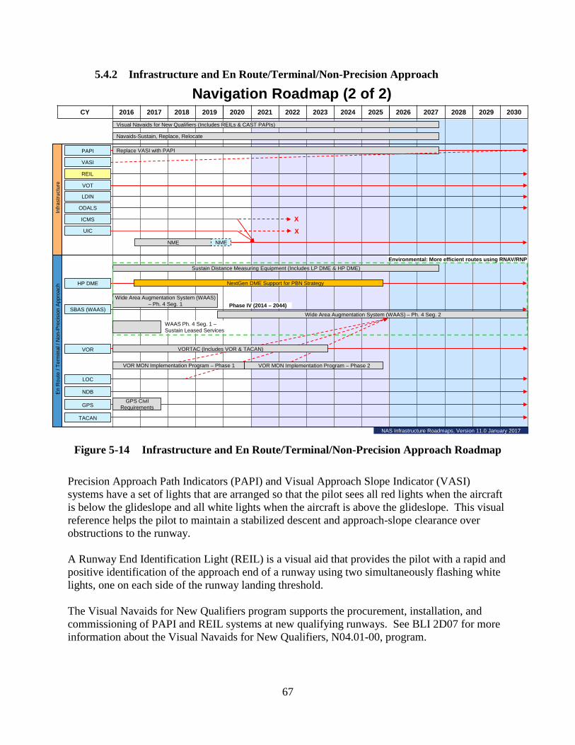
67
5.4.2 Infrastructure and En Route/Terminal/Non-Precision Approach
Figure 5-14 Infrastructure and En Route/Terminal/Non-Precision Approach Roadmap
Precision Approach Path Indicators (PAPI) and Visual Approach Slope Indicator (VASI) systems have a set of lights that are arranged so that the pilot sees all red lights when the aircraft is below the glideslope and all white lights when the aircraft is above the glideslope. This visual reference helps the pilot to maintain a stabilized descent and approach-slope clearance over obstructions to the runway. A Runway End Identification Light (REIL) is a visual aid that provides the pilot with a rapid and positive identification of the approach end of a runway using two simultaneously flashing white lights, one on each side of the runway landing threshold. The Visual Navaids for New Qualifiers program supports the procurement, installation, and commissioning of PAPI and REIL systems at new qualifying runways. See BLI 2D07 for more information about the Visual Navaids for New Qualifiers, N04.01-00, program.
CY 2016 2017 2018 2019 2020 2021 2022 2023 2024 2025 2026 2027 2028 2029 2030
Wide Area Augmentation System (WAAS) – Ph. 4 Seg. 1
Navigation Roadmap (2 of 2)
Infra
stru
ctur
e
PAPI
VASI
REIL
LDIN
ODALS
ICMS
HP DME
SBAS (WAAS)
VOR
LOC
NDB
GPS
TACAN
VOT
En
Rou
te /
Term
inal
/ N
on-P
reci
sion
App
roac
h
Environmental: More efficient routes using RNAV/RNP
Phase IV (2014 – 2044)
Replace VASI with PAPI
GPS Civil Requirements
NextGen DME Support for PBN Strategy
Sustain Distance Measuring Equipment (Includes LP DME & HP DME)
VOR MON Implementation Program – Phase 2
Visual Navaids for New Qualifiers (Includes REILs & CAST PAPIs)
Navaids-Sustain, Replace, Relocate
Wide Area Augmentation System (WAAS) – Ph. 4 Seg. 2
VOR MON Implementation Program – Phase 1
UIC
X
XNME NME
VORTAC (Includes VOR & TACAN)
WAAS Ph. 4 Seg. 1 –Sustain Leased Services
NAS Infrastructure Roadmaps, Version 11.0 January 2017

68
See Navigation Roadmap 1 in section 5.4.1 and BLI 2D09 for more information about the Navaids – Sustain, Replace, Relocate, N04.04-00, program. The Replace VASI with PAPI program will continue to replace the VASIs beyond 2030. See BLI 2D10 for more information about the Replace VASI with PAPI, N04.02-00, program. The VOR Test facility (VOT) is used to check and calibrate VOR receivers in aircraft. Lead In Light System (LDIN) and Omni-directional Airport Lighting System (ODALS) are installed at the end of runways to help pilots determine the active runway for landing. The Interlock Control and Monitoring System (ICMS) and Universal Interlock Controller (UIC) allow controllers to rapidly activate and deactivate the navigational aids at an airport. The Navaids Monitoring Equipment (NME) program will provide efficiencies by combining the control and monitoring functionality currently being provided by legacy systems, i.e. ICMS and UIC, into a single solution with one common software, training and logistics platform. The program is working towards a FID. See BLI 2D12 for more information about the NME, M08.41-02, program. High Power (HP) DME is a radio navigation aid used by pilots to determine the aircraft’s slant distance from the DME location based on its altitude. See the Navigation Roadmap 1 in section 5.4.1 and BLI 2D06 for more information about the Sustain DME, N09.00-00, program. The NextGen DME program will expand DME coverage in En Route and selected Terminal Airspace to provide a resilient, complimentary navigation service to enable DME/DME Area Navigation (RNAV) aircraft, without Inertial Reference Unit (IRU), to continue Performance Based Navigation (PBN) operations during disruptions of the Global Navigation Satellite System (GNSS). See BLI 2B19 for more information about the NextGen DME Support For Performance Based Navigation (PBN) Strategy, G01N.01-02, program. The Satellite-Based Augmentation System (SBAS), also called the Wide Area Augmentation System (WAAS), consists of a network of 38 ground reference stations located in North America that monitor the GPS satellite signals. Three master stations collect reference station data and calculate corrections and integrity messages for each GPS satellite. The WAAS messages are broadcast to user receivers via leased navigation transponders on three commercial GEO satellites. The receiver on the aircraft applies the corrections and uses the integrity information from the WAAS message to ensure the validity and obtains a precise navigation position. In addition to L1, a new GPS signal, L5 will be added on the next generation of satellites. The Wide Area Augmentation System (WAAS) – Phase IV Segment 1 incorporates WAAS infrastructure upgrades to support the use of the new L5 frequency and to prepare for the full dual frequency user capability planned for implementation in Dual Frequency Operations. WAAS Segment 2 will develop and deploy a WAAS Dual Frequency User Service that will provide correction and integrity data allowing usage of the L5 signal in the NAS. See BLI 2D03 for more information about the WAAS – Phase IV Segment 1, N12.01-07, and WAAS Phase IV Segment 2, N12.01-08, programs.

69
A Very High Frequency Omni-directional Range (VOR) is a ground-based Navaid that provides the bearing to the VOR and is used by general aviation aircraft for navigation in both en route and terminal airspace. The direct lines between VORs are used to define established air routes. A VOR collocated with a Tactical Air Navigation (TACAN) is called a VORTAC. The VORTAC program replaces, relocates, or improves VORs associated with Distance Measuring Equipment (DMEs) (VOR/DME) and VORs associated with TACANs. This includes installation of a Doppler VOR electronic and antenna kits to eliminate most signal reflection restrictions caused by obstacles causing electromagnetic interference such as trees, metal buildings, transmission lines, towers, or wind farms. See BLI 2D01 for more information about the VORTAC, N06.00-00, program. The VOR Minimum Operational Network (MON) Implementation Program will perform the work required to downsize the VOR network to the minimum required for use as a backup navigation system in the event of an unplanned GPS localized outage and allow aircraft not equipped with GPS to navigate and land under Instrument Flight Rules. This program supports the NAS transition from the current VOR airways to PBN consistent with NextGen goals. At the VOR MON Implementation Program Phase 1 FID in September 2015, the program was approved to discontinue approximately 74 VORs by the end of September 2020. The VOR MON Implementation Program Phase 2 is working towards a FID and will address additional sites to achieve the MON. See BLI 2D01 for more information about the VOR – MON Implementation Program – Phase 1, N06.01-01, and VOR – MON Implementation Program Phase – 2, N06.01-02, programs. The Localizer (LOC) is an ILS component that provides horizontal guidance to a runway end. When used as a stand-alone system without a Glideslope component, the LOC supports non-precision approach operations. SBAS (WAAS) will begin to replace that functionality at airports where only localizers are installed. A Non-Directional Beacon (NDB) supports navigation by providing the pilot with direction or bearing to the NDB station relative to the aircraft. The FAA will continue operating NDBs in some remote areas where it is not economically justified to install more modern navigational aids. The DoD operates the GPS. There are typically 24 to 30 active satellites in orbit, and a navigation receiver can determine an aircraft’s position by interpreting the data transmitted by the satellites in view of the aircraft’s antenna. Two GPS upgrades are expected in future years. The next generation of satellites will have a second frequency (L5) for civilian safety-of-life use. An aircraft receiver that receives both the existing L1 signal and the new L5 signal can internally calculate corrections that enhance the accuracy of the position calculation and eliminate the errors caused by ionospheric distortion. The GPS III family of satellites will be upgraded with an additional civil signal (L1C) and increased transmitting power. TACAN is the military equivalent of combined VOR and DME systems. VORTAC is a site where a VOR and TACAN are co-located and the VOR uses the TACAN for DME information.

70
5.5 Weather Roadmaps
Timely and accurate weather observations and forecasts are essential to aviation safety and for making the best use of aviation capacity. Weather information will be even more important when NextGen direct or user chosen trajectory routing becomes routine. Pilots need to know the direction and speed of winds aloft so that they can take advantage of tailwinds and minimize the effect of headwinds. They also need to know if there will be obstructions to visibility that restrict landings at their destination airport, and whether the runway is wet or dry and how that will affect braking action. Traffic flow managers and pilots use weather observations and forecasts to determine when they need to plan alternative routes to avoid severe weather. Pilots must avoid thunderstorms with hail and heavy rain, turbulence, and icing to avoid damage to the aircraft and the potential for injuring passengers. The FAA has a lead role in collecting and distributing aviation weather data – particularly hazardous weather. The FAA distributes hazardous weather information from its own systems and uses both the FAA and National Weather Service (NWS) computer forecast models based on data available from FAA and NWS sensors to develop forecasts for use by air traffic control facilities, pilots, airline operations centers, and other aviation-related facilities. Weather sensors include weather radars and surface observation systems that measure atmospheric parameters, such as surface temperature, barometric pressure, relative humidity, cloud bases and tops, prevailing wind speed and direction, and occurrences of wind shear and microbursts. These weather sensors provide real-time information to air traffic facilities and to centralized weather-forecasting models. Weather processing/dissemination/display systems organize and process the sensor’s observed data. Data from multiple sensors feed forecast models whose output can be disseminated and integrated in national and local processing and display systems that interpret broad weather trends affecting aviation operations. This information can then be sent to air traffic controllers, traffic flow managers, dispatchers, and pilots. Weather system implementation is broken down into two different roadmaps:
1. Roadmap 1 (figure 4-15) - Weather Sensors 2. Roadmap 2 (figure 4-16) - Weather Dissemination, Processing, and Display
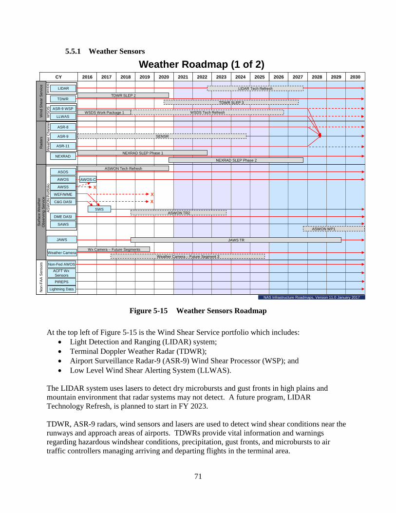
71
5.5.1 Weather Sensors
Figure 5-15 Weather Sensors Roadmap
At the top left of Figure 5-15 is the Wind Shear Service portfolio which includes:
• Light Detection and Ranging (LIDAR) system; • Terminal Doppler Weather Radar (TDWR); • Airport Surveillance Radar-9 (ASR-9) Wind Shear Processor (WSP); and • Low Level Wind Shear Alerting System (LLWAS).
The LIDAR system uses lasers to detect dry microbursts and gust fronts in high plains and mountain environment that radar systems may not detect. A future program, LIDAR Technology Refresh, is planned to start in FY 2023. TDWR, ASR-9 radars, wind sensors and lasers are used to detect wind shear conditions near the runways and approach areas of airports. TDWRs provide vital information and warnings regarding hazardous windshear conditions, precipitation, gust fronts, and microbursts to air traffic controllers managing arriving and departing flights in the terminal area.
CY 2016 2017 2018 2019 2020 2021 2022 2023 2024 2025 2026 2027 2028 2029 2030
WS
DS
WH
DE
Wx Camera – Future Segments
Wea
ther
Cha
nnel
AS
WO
N P
ortfo
lio
Weather Roadmap (1 of 2)
NEXRAD
ASR-9 WSP
PIREPS
Lightning Data
ACFT Wx Sensors
LIDAR
JAWS
Non-Fed AWOS
TDWR SLEP 3
NEXRAD SLEP Phase 1
WSDS Work Package 1LLWAS
TDWR
ASR-8
ASR-9
ASR-11
TDWR SLEP 2
Win
d S
hear
Ser
vice
Rad
ars
Sur
face
Wea
ther
O
bser
ving
Ser
vice
Non
-FA
A S
enso
rs
JAWS TR
Weather Camera
NEXRAD SLEP Phase 2
WSDS Tech Refresh
ASWON Tech Refresh
ASWON WP1
LIDAR Tech Refresh
ASOS
AWOS
WEF/WME
AWSS
C&G DASI
Weather Camera – Future Segment 3
DME DASI
SAWS
AWOS-C
SWS
XXX
ASWON TR2
SENSR
NAS Infrastructure Roadmaps, Version 11.0 January 2017

72
TDWR SLEP Phase 2 will replace TDWR components that have deteriorated due to aging, have become obsolete or unsupportable, and were not addressed in Phase 1. See BLI 2B01 for more information about the TDWR – SLEP – Phase 2, W03.03-02, program. The future program, TDWR – SLEP Phase 3, is planned to start in FY 2021 and will continue to replace TDWR components that have deteriorated due to aging; have become obsolete; or are unsupportable. Airports with significant wind shear risk that have a lower volume of air traffic are served by the ASR-9 WSP, a lower cost alternative to TDWR. The ASR-9 WSP processes weather from the two dimensional Doppler search radar signals, which are its standard format to detect wind shear which approximates the output of the TDWR. LLWAS consists of wind sensors located at 6 to 29 points around the runway thresholds to measure surface wind direction and velocity. The LLWAS computer systems compare the wind velocity and direction detected by these sensors at different locations to determine whether wind shear events are occurring at or near the runways. The sensors measure surface winds only and do not detect wind shear above the surface in the approach or departure paths. Wind Shear Detection Services (WSDS) Work Package 1 is a portfolio program that will address obsolescence and supportability issues of the legacy WSP, LLWAS, and Wind Measuring Equipment (WME) that determines and displays the wind speed and direction on the runways. See BLI 2A13 for more information about the WSDS – Work Package 1, W05.03-01, program. A future program, WSDS Technology Refresh, will address obsolescence of the WSP and LLWAS. The program will ensure continuation of the existing service levels provided by these legacy systems by upgrading the components necessary to resolve obsolescence and supportability issues. The next four systems are the ASR-8/9/11 Weather Channel and the Next Generation Weather Radar (NEXRAD) that detect precipitation, wind, and thunderstorms that affect aircraft in flight. NEXRAD is a long range weather radar that detects, analyzes, and transmits weather information for use by the ATC System Command Center, en route, terminal and flight service facilities. This weather information helps determine location, time of arrival, and severity of weather conditions to advise aircraft on recommended routes. See the description for SENSR under Surveillance Roadmap 1 in section 5.3.1 En Route Surveillance. There are currently 160 Next Generation Weather Radar (NEXRAD) systems that were developed and used under a tri-agency partnership between the Department of Commerce’s National Weather Service, Department of Defense, and FAA. The NEXRAD Service Life Extension Program (SLEP) Phase 1 is a refurbishment program to extend the service life of 12 FAA-owned NEXRAD systems until 2030 when a replacement capability is expected to be deployed. The NEXRAD SLEP Phase 2 will identify sustainability issues of the NEXRAD system in 2021 and if needed, will initiate investment analysis activities. See BLI 2A03 for more information about the NEXRAD – SLEP Phase 1, W02.02-02, and NEXRAD SLEP Phase 2, W02.02-03, programs.
73
The Aviation Surface Weather Observation Network (ASWON) is a portfolio program that consists of the Automated Surface Observing System (ASOS), Automated Weather Observation System (AWOS) and AWOS model C, Stand Alone Weather Sensors (SAWS), Digital Altimeter Setting Indicator (DASI), Wind Equipment F-420 Wind Sensor (WEF), and the AWOS Data Acquisition System (ADAS). All of these systems, except the ADAS, are located at airports and collectively measure and report weather conditions including temperature, barometric pressure, visibility, precipitation type and amount, cloud height and coverage, and wind speed and direction. The data collected is important to pilots and dispatchers as they prepare and file flight plans, and is vital for weather forecasting. The Wind Equipment F-400 Series (WEF) / Wind Measuring Equipment (WME) determine and display the wind direction and velocity on the runways. These systems feed data directly to air traffic control facilities and support automated broadcast of weather information to pilots and provide regular updates to forecast models. The ASWON Technology Refresh program will provide compatible technology upgrades and/or replacements to the five legacy ASWON systems (ASOS, AWOS, AWSS, DASI, and WEF) which are experiencing obsolescence, supportability, and maintainability issues. In September 2016, an In-Service Decision for Surface Weather System (SWS) was approved. SWS, within the ASWON program, will replace DASI, WEF, and WME sensors which are experiencing obsolescence, supportability, and maintainability issues. SWS hardware and software designed and developed by the FAA, will replace WME by FY 2018 and WEF/DASI by FY 2019. See BLI 2C01 for more information about the ASWON – Technology Refresh, W01.03-01, program. A future program, ASWON Technology Refresh-2 (ASWON TR-2), will provide required technology upgrades and/or replacements of the ASWON systems (ASOS, AWOS, SAWS, SWS and DASI) which are experiencing obsolescence, supportability, and maintainability issues. This technology refresh will allow these systems sustain the required level of service to support NAS operations. The Juneau Airport Weather System (JAWS) measures and transmits wind information to the Juneau Automated Flight Service Station (AFSS), Alaska Airlines, and the NWS for weather forecasting. Other Alaska aviation users access JAWS data via the Internet. It is essential for pilots to be aware of wind conditions that affect approach and departure paths because of the restrictive geographical features on both sides of the corridor in and out of the Juneau Airport. The Juneau Airport Wind System (JAWS) – Technology Refresh program will include replacement of computers and controllers, radios, firmware and software, anemometers, and profilers. The program is working towards a FID. See BLI 2A13 for more information about the JAWS – Technology Refresh, W10.01-02, program. Weather Cameras are installed at airports and strategic en route locations in Alaska to provide pilots, dispatchers, and flight service station specialists with real-time video weather information. These images are designated as an FAA Advisory weather product to be used for enhanced situational awareness and provide pilots, dispatchers, and Flight Service Station Specialists with
74
up-to-date weather conditions at airports, mountain passes, and strategic locations where weather is known to be a potential hazard. The Weather Camera Program – Future Segments sustains the operational Weather Cameras installed at airports and strategic en route locations in Alaska. The program ensures that camera network services are available, reliable, responsive, and accessible to pilots and aviation user groups. See BLI 2C04 for more information about the Weather Camera Program – Future Segments, M08.31-02, program. A future program, Weather Camera Program – Future Segment 3, is seeking to expand camera services to aviators that fly throughout the CONUS and Hawaii by using Third Party Image Hosting. The program will host images from state DOT owned airports and other critical en route locations such as mountain passes and other areas where weather-related accidents and flight interruptions are known to occur. The non-FAA sensors shown at the bottom of the roadmap are sources of weather information that improve FAA’s overall knowledge of weather conditions. Some states and smaller airports operate AWOS for weather observations. Inputs from these systems provide supplemental data to FAA sensors. Aircraft weather sensors can provide humidity, wind speed, and atmospheric pressure readings that are helpful in forecasting weather conditions. Pilot Reports (PIREPS) provide real time reports on the weather along major flight routes. Lightning Data systems provide air traffic facilities important information about the location and intensity of thunderstorms.
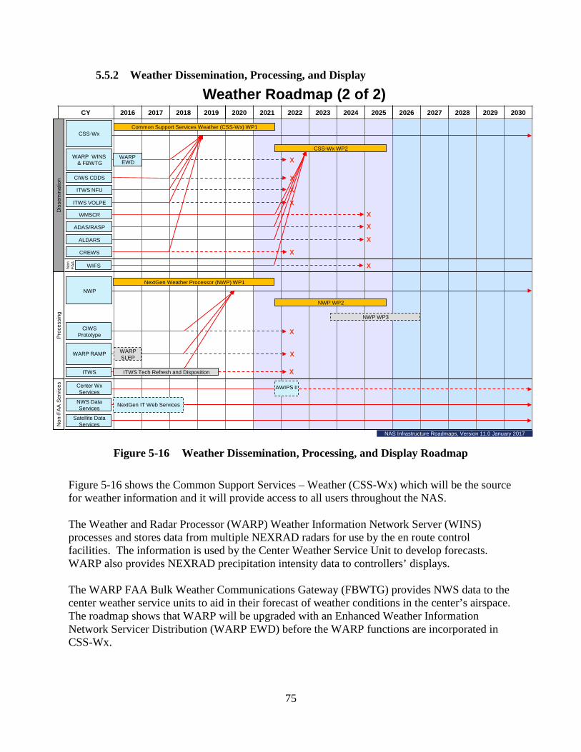
75
5.5.2 Weather Dissemination, Processing, and Display
Figure 5-16 Weather Dissemination, Processing, and Display Roadmap
Figure 5-16 shows the Common Support Services – Weather (CSS-Wx) which will be the source for weather information and it will provide access to all users throughout the NAS. The Weather and Radar Processor (WARP) Weather Information Network Server (WINS) processes and stores data from multiple NEXRAD radars for use by the en route control facilities. The information is used by the Center Weather Service Unit to develop forecasts. WARP also provides NEXRAD precipitation intensity data to controllers’ displays. The WARP FAA Bulk Weather Communications Gateway (FBWTG) provides NWS data to the center weather service units to aid in their forecast of weather conditions in the center’s airspace. The roadmap shows that WARP will be upgraded with an Enhanced Weather Information Network Servicer Distribution (WARP EWD) before the WARP functions are incorporated in CSS-Wx.
CY 2016 2017 2018 2019 2020 2021 2022 2023 2024 2025 2026 2027 2028 2029 2030
Weather Roadmap (2 of 2)
NWP WP3
NWP WP2
WARP RAMP
ITWS NFU
WARP WINS& FBWTG
Center Wx Services
ALDARS
Satellite DataServices
WMSCR
ITWS
CIWS Prototype
NWP
NWS DataServices
WIFS
ADAS/RASP
CIWS CDDS
ITWS VOLPE
X
X
X
X
Dis
sem
inat
ion
Pro
cess
ing
Non
-FA
A S
ervi
ces
Non
FAA
CSS-Wx WP2
X
X
X
X
X
CREWS
X
NextGen IT Web Services
WARP EWD
ITWS Tech Refresh and Disposition
AWIPS II
X
NextGen Weather Processor (NWP) WP1
WARP SLEP
X
Common Support Services Weather (CSS-Wx) WP1CSS-Wx
NAS Infrastructure Roadmaps, Version 11.0 January 2017

76
The Corridor Integrated Weather System (CIWS) gathers weather information along the busiest air traffic corridors to help air traffic specialists select the most efficient routes when they must divert traffic to avoid severe weather conditions. The CIWS Data Distribution System (CDDS) enables the existing CIWS system to distribute data to external NAS users so traffic management participants have the same information for daily route planning. The Integrated Terminal Weather System (ITWS) National Weather Service Filter Unit (ITWS NFU) will send data collected by FAA to the NWS to use for weather forecasting. The ITWS Volpe will establish an Internet connection to the ITWS weather data for external users. After 2018, ITWS NFU and ITWS Volpe data collection functions will be incorporated into the CSS-Wx. The FAA-operated Weather Message Switching Center Replacement (WMSCR) is a network with distribution nodes in Salt Lake City and Atlanta that collects and distributes nationwide weather information. The FAA will integrate WMSCR functionality into the CSS-Wx for weather information distribution. The Automated Weather Observation System (AWOS) Data Acquisition System/Regional ADAS Service Processor (ADAS/RASP) is a communications link that transmits AWOS/ASOS/AWSS data to air traffic facilities. ADAS also correlates cloud-to-ground lightning strike information to AWOS/ASOS/AWSS data to better determine the location of nearby thunderstorm activity. The Automated Lightning Detection and Reporting System (ALDARS) uses a network of sensors throughout the NAS to triangulate lightning strikes and then send messages to each automated airport station informing it of the proximity of any lightning strikes. The Center/TRACON automation system (CTAS) Remote Weather System (CREWS) collects data to help en route and terminal facility controllers coordinate the flows of air traffic into busy terminal facilities. The World Area Forecast System (WAFS) Internet File Service (WIFS) is a commercial service that provides weather information to support global flight operations. The CSS-Wx Work Package 1 program will deliver improved weather products for input into collaborative decision-making applications using information provided by the NextGen Weather Processor (NWP) (G04W.03-02), the National Oceanic and Atmospheric Administration’s (NOAA) NextGen Web Services, and other weather sources available to FAA and NAS users. CSS-Wx Work Package 2 will subsume additional legacy weather systems such as WMSCR, ADAS, ALDARS, and WIFS and provide additional Web services, filtering, and complex queries capabilities. See BLI 2A11 for more information about the System Wide Information Management SWIM – CCS-Wx – Work Package 1, G05C.01-06, and CCS-Wx – Work Package 2, G05C.01-09, programs. The WARP Radar and Mosaic Processor (RAMP) processes weather data and will remain in service until their functions can be incorporated in the NWP.
77
ITWS provides air traffic managers with graphic, full-color displays of essential weather information affecting major U.S. airports. ITWS integrates weather data from a number of sources and provides a single, easily used and understood display of supported products. ITWS – Sustainment & Disposition program is funding a lifetime buy of all necessary and available spare parts of the legacy hardware to attempt to sustain the current system until it is fully replaced by NWP. The program will also fund a contingency effort to mitigate potential accelerated hardware failures. See BLI 2B18 for more information about the ITWS – Sustainment & Disposition, W07.01-02, program. Next Generation Weather Processor (NWP), Work Package 1 (WP1) will replace and enhance the current processing and display functionality of the ITWS, CIWS, and WARP systems; generate aviation weather products with expanded coverage areas and faster update rates; generate 0-to-8 hour aviation weather products; generate safety critical wind shear alerts and real-time weather radar information; and perform translation of convective weather into weather constraint areas. NWP is planned to be operational it a key site in FY 2020. NWP WP2 will enhance weather algorithms and generate additional advanced products such as new radar mosaic, predictive products, weather avoidance fields, and terminal products. See BLI 2A16 for more information about the NWP, WP1, G04W.03-02 and NWP, WP2, G04W.03-03, programs. A future program, NWP WP3, will provide additional enhancements for future weather products beyond the scope of those in NWP WP2. The non-FAA services provide data from the NWS ground and satellite sensors to FAA for use by the NWS meteorologist who interpret and forecast weather at the FAA en route centers. Center Weather, NWS Data and Satellite Data Services comprise a distributed “virtual” database that will receive weather data directly from sensors, NWS, NOAA and other sources, and then, either automatically or by request, send this data to FAA facilities and users so that observations and forecasts can be more widely and consistently distributed via network-enabled communications (NextGen IT Web Services). Decision support tools will use this weather information to assist users in understanding weather constraints and taking actions to reduce risk for aviation operations. By FY2022, AWIPS II, the Advanced Weather Information Processing System, currently under development by the National Weather Service (NWS) and the National Center for Environmental Prediction is expected to replace current Center Weather Services. 6 Facilities The FAA maintains and operates thousands of staffed and unstaffed operational facilities that must be maintained and modernized. The largest staffed facilities are the 21 en route centers that house hundreds of employees and the equipment used to control aircraft in the en route environment. Other operational facilities with significant staff include more than 500 towers and 167 TRACON facilities that control arrival and departure traffic to and from airports in the

78
terminal environment. There are also more than 16,000 unstaffed facilities sheltering communications, navigation, surveillance equipment, and weather sensors. Much of this equipment is located in remote areas housed in buildings that need renovation with many having deteriorating steel towers and foundations. Some newer unstaffed buildings and structures require more frequent renovation because they are located in areas that are subject to harsher environmental conditions such as near the ocean or on a mountaintop. Replacing roofing, electric power generators, heating/cooling, and structural and security components of these facilities is essential to ensure successful operation of the NAS. The William J. Hughes Technical Center (WJHTC) in Atlantic City, NJ, and the Mike Monroney Aeronautical Center (MMAC) in Oklahoma City, OK, both have many buildings. Each year, these complexes receive funds to upgrade and/or replace infrastructure, and to improve and modernize buildings that support research and development, test and evaluation, operational and second level field support, training, logistics, and management functions. The MMAC operates under a lease from the Oklahoma City Airport Trust. The requested funds are used to pay the cost of the annual lease and to renovate buildings and supporting infrastructure, such as electrical and mechanical equipment. The WJHTC provides the integrated NAS platform used for research, development, test, evaluation, and field support for all NAS and NextGen acquisition programs within the FAA. Annual funding is used to upgrade and reconfigure the laboratories to accommodate acceptance testing for new equipment and to test modifications to existing equipment. The Terminal Air Traffic Control Facilities – Replace program includes planned funding for the replacement of existing air traffic control towers (ATCT) and TRACON facilities. The projects are funded in five segments and are scheduled based on FAA priorities. A project typically spans a period of 5-10 years from inception to completion depending upon its size and complexity. The budget for each segment of a project includes all of the funds needed to complete the segment but it may take more than one year to finish the work. Funding is allocated to the segments based upon FAA’s priorities with consideration given to maintaining the overall 5 year funding estimates for the program. The Terminal Air Traffic Control Facilities – Modernize program renovates or replaces specific exterior or interior components of existing towers, such as elevators, heating ventilation and cooling equipment, roofs, or other infrastructure that the FAA must upgrade to keep towers functioning. The FAA upgrades and improves Air Route Traffic Control Center (ARTCC) facilities by replacing heating and cooling systems, upgrading electrical power distribution systems, and providing other facility needs to meet mission requirements.
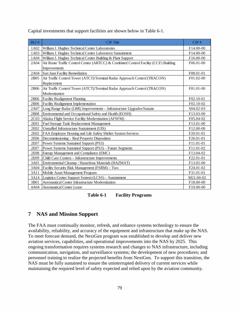
79
Capital investments that support facilities are shown below in Table 6-1.
Table 6-1 Facility Programs
7 NAS and Mission Support The FAA must continually monitor, refresh, and enhance systems technology to ensure the availability, reliability, and accuracy of the equipment and infrastructure that make up the NAS. To meet forecast demand, the NextGen program was established to develop and deliver new aviation services, capabilities, and operational improvements into the NAS by 2025. This ongoing transformation requires systems research and changes to NAS infrastructure, including communication, navigation, and surveillance systems; the development of new procedures; and personnel training to realize the projected benefits from NextGen. To support this transition, the NAS must be fully sustained to ensure the uninterrupted delivery of current services while maintaining the required level of safety expected and relied upon by the aviation community.
BLI # CIP Title CIP #1A02 William J. Hughes Technical Center Laboratories F14.00-001A03 William J. Hughes Technical Center Laboratory Sustainment F14.00-001A04 William J. Hughes Technical Center Building & Plant Support F16.00-002A04 Air Route Traffic Control Center (ARTCC) & Combined Control Facility (CCF) Building
ImprovementsF06.01-00
2A04 San Juan Facility Remediation F08.01-012B05 Air Traffic Control Tower (ATCT)/Terminal Radar Approach Control (TRACON)
ReplacementF01.02-00
2B06 Air Traffic Control Tower (ATCT)/Terminal Radar Approach Control (TRACON) Modernization
F01.01-00
2B06 Facility Realignment Planning F02.10-012B06 Facility Realignment Implementation F02.10-022A07 Long Range Radar (LRR) Improvements – Infrastructure Upgrades/Sustain S04.02-032B08 Environmental and Occupational Safety and Health (EOSH) F13.03-002C03 Alaska Flight Service Facility Modernization (AFSFM) F05.04-022E01 Fuel Storage Tank Replacement Management F13.01-002E02 Unstaffed Infrastructure Sustainment (UIS) F12.00-002E02 FAA Employee Housing and Life Safety Shelter System Services F20.01-012E06 Decommissioning – Real Property Disposition F26.01-012E07 Power Systems Sustained Support (PS3) F11.01-012E07 Power Systems Sustained Support (PS3) – Future Segments F11.01-022E08 Energy Management and Compliance (EMC) F13.04-022E09 Child Care Centers – Infrastructure Improvements F22.01-013A01 Environmental Cleanup / Hazardous Materials (HAZMAT) F13.02-003A04 Facility Security Risk Management (FSRM) – Two F24.01-023A11 Mobile Asset Management Program F31.01-013A14 Logistics Center Support System (LCSS) – Sustainment M21.04-023B01 Aeronautical Center Infrastructure Modernization F18.00-004A04 Aeronautical Center Lease F19.00-00

80
Capital investments that support NAS and Mission Support are shown below in Table 7-1.
Table 7-1 NAS and Mission Support Programs
BLI # CIP Title CIP #1A01 Runway Incursion Reduction Program (RIRP) – ATDP S09.02-001A01 System Capacity, Planning and Improvements – ATDP M08.28-001A01 Operations Concept Validation and Infrastructure Evolution – ATDP M08.29-001A01 Major Airspace Redesign – ATDP M08.28-041A01 Strategy and Evaluation – ATDP M46.01-011A01 Dynamic Capital Planning M47.01-011A01 Operational Analysis and Reporting System (OARS) M08.32-031A01 Operations Network (OPSNET) Replacement – ATDP A37.01-011A01 Enterprise Management, Integration, Planning, & Performance Evaluation for NextGen M03.04-011A01 Operational Modeling Analysis and Data M52.01-011A01 Enterprise Information Management (EIM) G05M.04-012A17 Airborne Collision Avoidance System X (ACAS X) – Segment 1 M54.01-012D08 Instrument Flight Procedures Automation (IFPA) – Technology Refresh, Segment 1 A14.02-022D08 Instrument Flight Procedures Automation (IFPA) – Sustainment 2 A14.02-032E03 Aircraft Related Equipment (ARE) Program M12.00-002E03 NextGen Flight Simulation Testing and Research Technologies (Flight START) – Technology
Refresh Program - Additional ProjectsM12.01-04
2E03 William J. Hughes Technical Center Laboratories – Flight Program Consolidation – Sustainment
F14.01-01
2E11 Data, Visualization, Analysis and Reporting System (DVARS) M08.28-053A05 Information Systems Security M31.00-003A05 Critical Infrastructure Cybersecurity M31.05-013A10 National Test Equipment Program M17.01-013A13 National Airspace System (NAS) Training - Equipment Modernization – Training Simulators –
Tower Simulation SystemM20.01-04
3B02 Distance Learning M10.00-004A01 CIP Systems Engineering & Development Support – System Engineering Contract M03.03-014A01 Provide Air Navigation Facilities (ANF)/Air Traffic Control (ATC) Support (Quick Response) M08.01-004A02 Program Support Leases M08.06-004A03 NAS Regional/Center Logistics Support Services M05.00-004A05 NAS Integration Support Contract (NISC) M22.00-004A05 Configuration Management Automation (CMA) M03.01-024A06 Technical Support Services Contract (TSSC) M02.00-004A07 Resource Tracking Program (RTP) M08.14-004A08 CIP Systems Engineering & Technical Assistance – MITRE M03.02-00

81
8 Estimated Funding by Budget Line Item (BLI) The following table shows funding by BLI with dollars in millions for the capital programs in the FY 2018 to FY 2022 time frame. The funding levels in this table reflect policy levels assumed in the President’s Budget. The Administration has proposed to shift FAA’s air traffic control function to a non-governmental, non-profit organization in 2021. Under this proposal, the non-governmental, non-profit organization would manage and invest in those capital programs that support air traffic control starting in 2021.

82
BLI
N
umbe
rC
apit
al B
udge
t Li
ne I
tem
(B
LI)
Pro
gram
FY 2
018
Bud
get
FY 2
019
Est.
FY 2
020
Est.
FY 2
021
Est.
FY 2
022
Est.
Act
ivit
y 1:
Eng
inee
ring
, Dev
elop
men
t, T
est
and
Eval
uati
on
$145
.6$1
54.8
$179
.4$1
89.9
$194
.41A
01 A
dvan
ced
Tech
nolo
gy D
evel
opm
ent a
nd P
roto
typi
ng (
ATDP
)$2
6.8
$34.
6$3
8.0
$37.
0$3
7.0
1A02
Will
iam
J. H
ughe
s Te
chni
cal C
ente
r La
bora
tory
Impr
ovem
ent
$1.0
$1.0
$1.0
$1.0
$1.0
1A03
Will
iam
J. H
ughe
s Te
chni
cal C
ente
r La
bora
tory
Sus
tain
men
t$1
8.0
$15.
9$1
5.9
$15.
9$1
5.9
1A04
Will
iam
J. H
ughe
s Te
chni
cal C
ente
r In
fras
truc
ture
Sus
tain
men
t$1
0.0
$10.
0$1
0.0
$10.
0$1
0.0
1A05
Nex
tGen
– S
epar
atio
n M
anag
emen
t Por
tfolio
$13.
5$1
3.0
$22.
5$2
1.5
$26.
51A
06 N
extG
en –
Tra
ffic
Flow
Man
agem
ent P
ortfo
lio$1
0.8
$14.
0$1
1.0
$13.
0$1
8.0
1A07
Nex
tGen
– O
n De
man
d NA
S Po
rtfo
lio$1
2.0
$16.
5$2
5.5
$31.
5$2
6.0
1A08
Nex
tGen
– N
AS In
fras
truc
ture
Por
tfolio
$17.
5$1
3.5
$17.
5$2
0.0
$20.
01A
09 N
extG
en –
Sup
port
Por
tfolio
$12.
0$1
2.8
$11.
0$1
1.0
$11.
01A
10 N
extG
en –
Unm
anne
d Ai
rcra
ft Sy
stem
s (U
AS)
$15.
0$1
4.0
$17.
0$2
0.0
$20.
01A
11 N
extG
en –
Ent
erpr
ise,
Con
cept
Dev
elop
men
t, Hu
man
Fac
tors
, & D
emon
stra
tions
Po
rtfo
lio$9
.0$9
.5$1
0.0
$9.0
$9.0
$1,7
18.8
$1,6
90.7
$1,6
69.4
$1,6
42.5
$1,6
59.9
A. E
n R
oute
Pro
gram
s $7
53.9
$687
.2$6
68.5
$633
.1$6
48.4
2A01
Nex
tGen
– E
n Ro
ute
Auto
mat
ion
Mod
erni
zatio
n (E
RAM
) –
Syst
em E
nhan
cem
ents
and
Te
chno
logy
Ref
resh
$76.
7$1
01.7
$91.
6$8
5.5
$82.
7
2A02
En
Rout
e Co
mm
unic
atio
ns G
atew
ay (
ECG)
$2.7
$1.7
$2.7
$2.7
$0.7
2A03
Nex
t Gen
erat
ion
Wea
ther
Rad
ar (
NEXR
AD)
$5.5
$5.5
$4.0
$6.1
$5.4
2A04
Air
Rout
e Tr
affic
Con
trol
Cen
ter
(ART
CC)
& C
ombi
ned
Cont
rol F
acili
ty (
CCF)
Bui
ldin
g Im
prov
emen
ts$1
00.4
$89.
4$8
3.0
$83.
0$8
3.0
2A05
Air
Traf
fic M
anag
emen
t (AT
M)
– Tr
affic
Flo
w M
anag
emen
t (TF
M)
$4.9
$6.2
$20.
0$2
5.2
$27.
92A
06 A
ir/Gr
ound
Com
mun
icat
ions
Infr
astr
uctu
re$9
.8$8
.8$8
.3$8
.3$8
.32A
07 A
ir Tr
affic
Con
trol
En
Rout
e Ra
dar
Faci
litie
s Im
prov
emen
ts$5
.4$6
.6$6
.5$6
.5$6
.52A
08 V
oice
Sw
itchi
ng C
ontr
ol S
yste
m (
VSCS
)$1
2.8
$11.
4$1
1.7
$12.
1$1
2.4
2A09
Oce
anic
Aut
omat
ion
Syst
em$2
3.1
$17.
5$1
3.6
$10.
0$1
0.0
2A10
Nex
t Gen
erat
ion
Very
Hig
h Fr
eque
ncy
Air/
Grou
nd C
omm
unic
atio
ns S
yste
m (
NEXC
OM
)$5
3.0
$50.
0$6
0.0
$64.
0$6
5.0
2A11
Nex
tGen
– S
yste
m-W
ide
Info
rmat
ion
Man
agem
ent (
SWIM
)$5
0.1
$54.
9$4
2.6
$28.
5$3
0.8
2A12
Nex
tGen
– A
utom
atic
Dep
ende
nt S
urve
illan
ce -
Bro
adca
st (
ADS-
B) N
AS W
ide
Impl
emen
tatio
n$1
39.2
$118
.6$1
23.5
$125
.0$1
25.0
2A13
Win
d Sh
ear
Dete
ctio
n Se
rvic
e (W
SDS)
$1.0
$1.0
$1.0
$1.0
$0.7
2A14
Nex
tGen
– C
olla
bora
tive
Air
Traf
fic M
anag
emen
t Tec
hnol
ogie
s Po
rtfo
lio$9
.0$1
7.7
$24.
3$1
5.0
$5.0
2A15
Nex
tGen
– T
ime
Base
d Fl
ow M
anag
emen
t (TB
FM)
Port
folio
$40.
5$2
3.8
$36.
3$4
4.8
$46.
92A
16 N
extG
en –
Nex
t Gen
erat
ion
Wea
ther
Pro
cess
or (
NWP)
$35.
5$2
4.3
$16.
0$6
.2$3
2.4
2A17
Airb
orne
Col
lisio
n Av
oida
nce
Syst
em X
(AC
AS X
)$7
.7$9
.7$6
.9$5
.1$0
.0
Act
ivit
y 2:
Pro
cure
men
t an
d M
oder
niza
tion
of
Air
Tra
ffic
C
ontr
ol F
acili
ties
and
Equ
ipm
ent

83
BLI
N
umbe
rC
apit
al B
udge
t Li
ne I
tem
(B
LI)
Pro
gram
FY 2
018
Bud
get
FY 2
019
Est.
FY 2
020
Est.
FY 2
021
Est.
FY 2
022
Est.
2A18
Nex
tGen
– D
ata
Com
mun
icat
ion
in s
uppo
rt o
f Nex
tGen
$154
.1$1
13.5
$89.
6$7
2.1
$64.
02A
19 O
ffsho
re A
utom
atio
n$1
1.0
$14.
0$1
5.0
$20.
0$2
5.0
2A20
Nex
tgen
– A
dvan
ced
Surv
eilla
nce
Enha
nced
Pro
cedu
ral S
epar
atio
n (A
SEPS
)$4
.4$0
.0$0
.0$0
.0$0
.02A
21 E
n Ro
ute
Impr
ovem
ents
$3.0
$1.0
$2.0
$2.0
$2.0
2A22
Com
mer
cial
Spa
ce In
tegr
atio
n$4
.5$1
0.0
$10.
0$1
0.1
$14.
8
B. T
erm
inal
Pro
gram
s $5
41.5
$526
.1$5
37.4
$555
.1$5
64.4
2B01
Ter
min
al D
oppl
er W
eath
er R
adar
(TD
WR)
– P
rovi
de$3
.8$4
.5$2
.2$0
.0$0
.02B
02 S
tand
ard
Term
inal
Aut
omat
ion
Repl
acem
ent S
yste
m (
STAR
S) S
usta
in$8
6.7
$66.
9$4
0.0
$62.
0$5
0.0
2B03
Ter
min
al A
utom
atio
n M
oder
niza
tion/
Rep
lace
men
t Pro
gram
(TA
MR
Phas
e 3)
$66.
1$8
.0$0
.0$0
.0$0
.02B
04 T
erm
inal
Aut
omat
ion
Prog
ram
$8.5
$8.5
$9.0
$9.0
$9.0
2B05
Ter
min
al A
ir Tr
affic
Con
trol
Fac
ilitie
s –
Repl
ace
$31.
1$1
9.2
$10.
0$7
0.0
$143
.52B
06 A
TCT/
Term
inal
Rad
ar A
ppro
ach
Cont
rol (
TRAC
ON)
Fac
ilitie
s –
Impr
ove
$56.
8$9
9.7
$96.
0$5
5.0
$42.
52B
07 T
erm
inal
Voi
ce S
witc
h Re
plac
emen
t (TV
SR)
$6.0
$6.0
$6.0
$5.0
$5.0
2B08
NAS
Fac
ilitie
s O
SHA
and
Envi
ronm
enta
l Sta
ndar
ds C
ompl
ianc
e$4
6.7
$41.
9$4
2.0
$42.
0$4
2.0
2B09
Airp
ort S
urve
illan
ce R
adar
(AS
R-9)
Ser
vice
Life
Ext
ensi
on P
rogr
am (
SLEP
)$1
1.4
$18.
9$1
4.0
$25.
5$9
.02B
10 T
erm
inal
Dig
ital R
adar
(AS
R-11
) Te
chno
logy
Ref
resh
$3.2
$1.0
$4.4
$4.4
$4.4
2B11
Run
way
Sta
tus
Ligh
ts (
RWSL
)$2
.8$2
.0$3
.5$3
.5$5
.02B
12 N
extG
en –
Nat
iona
l Airs
pace
Sys
tem
Voi
ce S
yste
m (
NVS)
$68.
8$4
2.8
$116
.6$1
05.5
$106
.62B
13 In
tegr
ated
Dis
play
Sys
tem
(ID
S)$5
.0$1
8.0
$24.
0$3
4.2
$45.
02B
14 R
emot
e M
onito
ring
and
Logg
ing
Syst
em (
RMLS
)$7
.4$1
8.1
$16.
4$1
5.6
$16.
72B
15 M
ode
S Se
rvic
e Li
fe E
xten
sion
Pro
gram
(SL
EP)
$20.
9$1
5.4
$21.
0$1
9.7
$8.8
2B16
Nex
tGen
– T
erm
inal
Flig
ht D
ata
Man
ager
(TF
DM)
$90.
4$1
19.0
$112
.8$7
8.7
$47.
92B
17 N
AS V
oice
Rec
orde
r Pr
ogra
m (
NVRP
)$5
.0$1
4.0
$14.
5$1
7.0
$21.
02B
18 In
tegr
ated
Ter
min
al W
eath
er S
yste
m (
ITW
S) S
usta
inm
ent
$1.0
$2.1
$0.0
$0.0
$0.0
2B19
Nex
tGen
– P
erfo
rman
ce B
ased
Nav
igat
ion
& M
etro
plex
Por
tfolio
$20.
0$2
0.0
$5.0
$8.0
$8.0
C. F
light
Ser
vice
Pro
gram
s $2
8.0
$23.
9$1
4.8
$4.7
$2.8
2C01
Avi
atio
n Su
rfac
e W
eath
er O
bser
vatio
n Sy
stem
$10.
0$1
0.0
$2.0
$0.0
$0.0
2C02
Fut
ure
Flig
ht S
ervi
ces
Prog
ram
(FF
SP)
$14.
0$1
0.1
$10.
1$2
.0$0
.02C
03 A
lask
a Fl
ight
Ser
vice
Fac
ility
Mod
erni
zatio
n (A
FSFM
)$2
.7$2
.7$2
.7$2
.7$2
.72C
04 W
eath
er C
amer
a Pr
ogra
m$1
.3$1
.1$0
.0$0
.0$0
.1
D. L
andi
ng a
nd N
avig
atio
n A
ids
Prog
ram
s $1
52.4
$157
.7$1
60.2
$173
.6$1
81.9
2D01
VHF
Om
nidi
rect
iona
l Rad
io R
ange
(VO
R) w
ith D
ista
nce
Mea
surin
g Eq
uipm
ent (
DME)
$11.
0$1
8.5
$20.
0$1
9.3
$21.
42D
02 In
stru
men
t Lan
ding
Sys
tem
s (I
LS)
$7.0
$6.0
$11.
0$1
1.0
$11.
02D
03 W
ide
Area
Aug
men
tatio
n Sy
stem
(W
AAS)
for
GPS
$102
.3$9
6.3
$93.
6$9
9.5
$98.
5

84
BLI
N
umbe
rC
apit
al B
udge
t Li
ne I
tem
(B
LI)
Pro
gram
FY 2
018
Bud
get
FY 2
019
Est.
FY 2
020
Est.
FY 2
021
Est.
FY 2
022
Est.
2D04
Run
way
Vis
ual R
ange
(RV
R)$4
.0$7
.0$6
.0$6
.0$6
.02D
05 A
ppro
ach
Ligh
ting
Syst
em Im
prov
emen
t Pro
gram
(AL
SIP)
$3.0
$5.0
$5.0
$5.0
$5.0
2D06
Dis
tanc
e M
easu
ring
Equi
pmen
t (DM
E)$3
.0$5
.5$5
.0$5
.0$8
.02D
07 V
isua
l Nav
aids
– E
stab
lish/
Expa
nd$2
.0$1
.0$2
.0$2
.0$2
.02D
08 In
stru
men
t Flig
ht P
roce
dure
s Au
tom
atio
n (I
FPA)
$8.5
$1.4
$1.2
$0.8
$0.0
2D09
Nav
igat
ion
and
Land
ing
Aids
– S
ervi
ce L
ife E
xten
sion
Pro
gram
(SL
EP)
$3.0
$5.0
$5.0
$10.
0$1
0.0
2D10
VAS
I Rep
lace
men
t – R
epla
ce w
ith P
reci
sion
App
roac
h Pa
th In
dica
tor
$5.0
$7.0
$10.
0$1
5.0
$20.
02D
11 R
unw
ay S
afet
y Ar
eas
– Na
viga
tion
Miti
gatio
n$1
.6$2
.0$1
.4$0
.0$0
.02D
12 N
AVAI
DS M
onito
ring
Equi
pmen
t$2
.0$3
.0$0
.0$0
.0$0
.0
E. O
ther
ATC
Fac
iliti
es P
rogr
ams
$243
.0$2
95.8
$288
.6$2
76.0
$262
.42E
01 F
uel S
tora
ge T
ank
Repl
acem
ent a
nd M
anag
emen
t$2
8.1
$25.
7$2
2.0
$22.
0$2
2.0
2E02
Uns
taffe
d In
fras
truc
ture
Sus
tain
men
t$3
5.7
$50.
9$4
9.9
$46.
7$4
6.3
2E03
Airc
raft
Rela
ted
Equi
pmen
t Pro
gram
$12.
5$1
6.1
$16.
1$1
6.1
$12.
12E
04 A
irpor
t Cab
le L
oop
Syst
ems
– Su
stai
ned
Supp
ort
$8.0
$10.
0$1
0.0
$10.
0$1
0.0
2E05
Ala
skan
Sat
ellit
e Te
leco
mm
unic
atio
n In
fras
truc
ture
(AS
TI)
$20.
9$1
6.3
$9.4
$4.0
$0.0
2E06
Fac
ilitie
s De
com
mis
sion
ing
$13.
9$9
.0$1
0.0
$10.
0$1
0.0
2E07
Ele
ctric
al P
ower
Sys
tem
s –
Sust
ain/
Supp
ort
$110
.0$1
47.7
$140
.0$1
33.0
$135
.02E
08 E
nerg
y M
anag
emen
t and
Com
plia
nce
(EM
C)$2
.4$2
.4$6
.2$6
.2$0
.02E
09 C
hild
Car
e Ce
nter
Sus
tain
men
t$1
.0$1
.0$1
.5$1
.0$0
.02E
10 F
AA T
elec
omm
unic
atio
ns In
fras
truc
ture
2$2
.0$6
.7$1
1.5
$15.
0$1
5.0
2E11
Dat
a, V
isua
lizat
ion,
Ana
lysi
s an
d Re
port
ing
Syst
em (
DVAR
S)$5
.5$4
.5$4
.5$4
.5$4
.52E
12 T
ime-
Divi
sion
Mul
tiple
to In
tern
et P
roto
col (
TDM
-to-
IP)
Mig
ratio
n$3
.0$3
.0$4
.0$4
.0$4
.02E
13X
Inde
pend
ent O
pera
tiona
l Ass
essm
ent
$0.0
$2.5
$3.5
$3.5
$3.5
Act
ivit
y 3:
Non
-Air
Tra
ffic
Con
trol
Fac
iliti
es a
nd E
quip
men
t $1
93.0
$196
.1$1
85.2
$199
.6$1
72.5
A. S
uppo
rt P
rogr
ams
$178
.0$1
81.1
$170
.2$1
84.6
$157
.53A
01 H
azar
dous
Mat
eria
ls M
anag
emen
t$3
5.3
$29.
8$3
1.0
$31.
0$3
1.0
3A02
Avi
atio
n Sa
fety
Ana
lysi
s Sy
stem
(AS
AS)
$12.
0$1
6.0
$19.
7$2
0.3
$20.
53A
03 N
atio
nal A
irspa
ce S
yste
m (
NAS)
Rec
over
y Co
mm
unic
atio
ns (
RCO
M)
$12.
0$1
2.0
$12.
0$1
2.0
$12.
03A
04 F
acili
ty S
ecur
ity R
isk
Man
agem
ent
$20.
4$1
7.8
$15.
0$1
4.9
$12.
13A
05 In
form
atio
n Se
curit
y$2
0.7
$16.
0$1
7.8
$18.
5$1
8.2
3A06
Sys
tem
App
roac
h fo
r Sa
fety
Ove
rsig
ht (
SASO
)$2
5.8
$25.
4$2
3.1
$23.
7$2
5.4
3A07
Avi
atio
n Sa
fety
Kno
wle
dge
Man
agem
ent E
nviro
nmen
t (AS
KME)
$4.0
$4.0
$5.0
$8.4
$9.8
3A08
Aer
ospa
ce M
edic
al E
quip
men
t Nee
ds (
AMEN
)$7
.0$1
9.6
$12.
8$1
8.9
$5.0
3A09
Nex
tGen
– S
yste
m S
afet
y M
anag
emen
t Por
tfolio
$16.
2$1
4.2
$17.
0$1
7.0
$17.
0

85
BLI
N
umbe
rC
apit
al B
udge
t Li
ne I
tem
(B
LI)
Pro
gram
FY 2
018
Bud
get
FY 2
019
Est.
FY 2
020
Est.
FY 2
021
Est.
FY 2
022
Est.
3A10
Nat
iona
l Tes
t Equ
ipm
ent P
rogr
am$4
.0$5
.0$3
.0$3
.0$3
.03A
11 M
obile
Ass
ets
Man
agem
ent P
rogr
am$3
.6$2
.2$1
.5$2
.0$2
.03A
12 A
eros
pace
Med
icin
e Sa
fety
Info
rmat
ion
Syst
em (
AMSI
S)$1
4.0
$16.
1$9
.3$9
.2$0
.03A
13 T
ower
Sim
ulat
ion
Syst
em (
TSS)
Tec
hnol
ogy
Refr
esh
$3.0
$3.0
$3.0
$0.0
$0.0
3A14
X L
ogis
tics
Supp
ort S
yste
m a
nd F
acili
ties
(LSS
F)$0
.0$0
.0$0
.0$5
.7$1
.5
B. T
rain
ing,
Equ
ipm
ent
and
Faci
litie
s $1
5.0
$15.
0$1
5.0
$15.
0$1
5.0
3B01
Aer
onau
tical
Cen
ter
Infr
astr
uctu
re M
oder
niza
tion
$14.
0$1
4.0
$14.
0$1
4.0
$14.
03B
02 D
ista
nce
Lear
ning
$1.0
$1.0
$1.0
$1.0
$1.0
Act
ivit
y 4:
Fac
iliti
es a
nd E
quip
men
t M
issi
on S
uppo
rt
$225
.0$2
26.2
$233
.6$2
33.1
$233
.54A
01 S
yste
m E
ngin
eerin
g an
d De
velo
pmen
t Sup
port
$35.
7$3
8.0
$38.
0$3
8.0
$38.
04A
02 P
rogr
am S
uppo
rt L
ease
s$4
7.0
$47.
0$5
0.0
$50.
0$5
0.0
4A03
Log
istic
s an
d Ac
quis
ition
Sup
port
Ser
vice
s$1
1.0
$11.
0$1
1.0
$11.
0$1
1.0
4A04
Mik
e M
onro
ney
Aero
naut
ical
Cen
ter
Leas
es$1
9.7
$20.
2$2
0.6
$21.
1$2
1.5
4A05
Tra
nsiti
on E
ngin
eerin
g Su
ppor
t$1
9.9
$17.
0$1
6.0
$15.
0$1
5.0
4A06
Tec
hnic
al S
uppo
rt S
ervi
ces
Cont
ract
(TS
SC)
$23.
0$2
3.0
$23.
0$2
3.0
$23.
04A
07 R
esou
rce
Trac
king
Pro
gram
(RT
P)$6
.0$6
.0$8
.0$8
.0$8
.04A
08 C
ente
r fo
r Ad
vanc
ed A
viat
ion
Syst
em D
evel
opm
ent (
CAAS
D)$5
7.0
$60.
0$6
0.0
$60.
0$6
0.0
4A09
Nex
tGen
– A
eron
autic
al In
form
atio
n M
anag
emen
t Pro
gram
$4.7
$2.0
$5.0
$5.0
$5.0
4A10
Nex
tGen
– C
ross
Age
ncy
Next
Gen
Man
agem
ent
$1.0
$2.0
$2.0
$2.0
$2.0
Act
ivit
y 5:
Per
sonn
el C
ompe
nsat
ion,
Ben
efit
s an
d T
rave
l$4
83.8
$498
.3$4
98.4
$500
.9$5
05.7
5A01
Per
sonn
el a
nd R
elat
ed E
xpen
ses
$483
.8$4
98.3
$498
.4$5
00.9
$505
.7
Note
: BL
I num
bers
with
X r
epre
sent
out
year
pro
gram
s no
t req
uest
ed in
the
FY 2
018
Pres
iden
t's B
udge
t.No
te:
The
fund
ing
leve
ls in
this
tabl
e re
flect
pol
icy
leve
ls a
ssum
ed in
the
Pres
iden
t’s
Budg
et. T
he A
dmin
istr
atio
n ha
s pr
opos
ed to
shi
ft FA
A’s
air
traf
fic c
ontr
ol fu
nctio
n to
a
non-
gove
rnm
enta
l, no
n-pr
ofit
orga
niza
tion
in 2
021.
Und
er th
is p
ropo
sal,
the
non-
gove
rnm
enta
l, no
n-pr
ofit
orga
niza
tion
wou
ld m
anag
e an
d in
vest
in th
ose
capi
tal
prog
ram
s th
at s
uppo
rt a
ir tr
affic
con
trol
sta
rtin
g in
202
1.
Tota
l Yea
r Fu
ndin
g$2
,766
.2$2
,766
.0$2
,766
.0$2
,766
.0$2
,766
.0
Targ
ets
$2,7
66.2
$2,7
66.0
$2,7
66.0
$2,7
66.0
$2,7
66.0

86
9 Information for Major Capital Programs Because of the criticality of on-budget and on-time acquisitions to the efficient transition to NextGen, the Government Accountability Office (GAO) was directed to determine the status of Air Traffic Organization’s performance in acquiring ATC systems. In response to a prior GAO recommendation to identify regular reporting to Congress and the public on FAA’s overall performance in acquiring ATC systems, the table below provides the most recent information on FAA’s major capital programs. FAA’s major programs are defined as those classified as Acquisition Category (ACAT) 1, 2, 3, or are of strategic importance to the agency. These are typically programs with total F&E costs greater than $100 million and/or those that have significant impact, complexity, risk, sensitivity, safety, or security issues. For more information on ACATs see: http://fast.faa.gov/NFFCA_Acquisition_Categories.cfm .
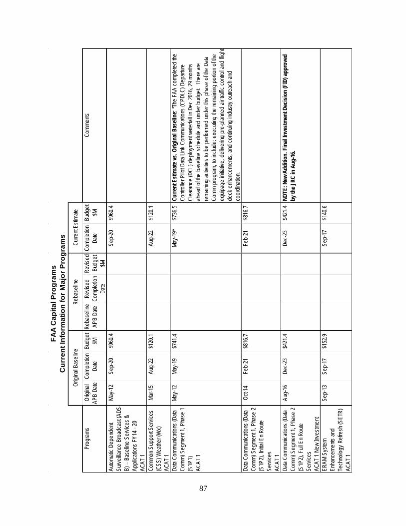
87
Prog
rams
Origi
nal
APB
Date
Comp
letion
Da
teBu
dget
$MRe
base
line
APB
Date
Revis
ed
Comp
letion
Da
te
Revis
ed
Budg
et $M
Comp
letion
Da
teBu
dget
$MCo
mmen
ts
Autom
atic D
epen
dent
Surve
illanc
e Br
oadc
ast (A
DS-
B) –
Base
line
Servi
ces &
Ap
plica
tions
FY1
4 - 20
AC
AT 1
May-1
2Se
p-20
$960
.4Se
p-20
$960
.4
Comm
on S
uppo
rt Ser
vices
(C
SS) W
eathe
r (W
x) AC
AT 1
Mar-1
5Au
g-22
$120
.1Au
g-22
$120
.1
Data
Comm
unica
tions
(Data
Co
mm) S
egme
nt 1,
Phas
e 1
(S1P
1)AC
AT 1
May-1
2Ma
y-19
$741
.4Ma
y-19*
$736
.5Cu
rrent
Esti
mate
vs. O
rigin
al Ba
selin
e: *T
he F
AA co
mplet
ed th
e Co
ntroll
er P
ilot D
ata Li
nk C
ommu
nicati
ons (
CPDL
C) D
epart
ure
Clea
rance
(DCL
) dep
loyme
nt wa
terfal
l in D
ec 20
16, 2
9 mon
ths
ahea
d of
the b
aseli
ne sc
hedu
le an
d un
der b
udge
t. Th
ere
are
rema
ining
activ
ities t
o be
per
forme
d un
der th
is ph
ase
of the
Data
Co
mm p
rogr
am, to
inclu
de: e
xecu
ting
the re
maini
ng p
ortio
n of th
e eq
uipag
e ini
tiativ
e, d
elive
ring
pre-
plann
ed ai
r traff
ic co
ntrol
and
flight
deck
enh
ance
ments
, and
conti
nuing
indu
stry o
utrea
ch an
d co
ordin
ation
.Da
ta Co
mmun
icatio
ns (D
ata
Comm
) Seg
ment
1, Ph
ase
2 (S
1P2),
Initia
l En R
oute
Servi
ces
ACAT
1
Oct-1
4Fe
b-21
$816
.7Fe
b-21
$816
.7
Data
Comm
unica
tions
(Data
Co
mm) S
egme
nt 1,
Phas
e 2
(S1P
2), F
ull E
n Rou
te Se
rvice
sAC
AT 1
New
Inves
tmen
t
Aug-
16De
c-23
$421
.4De
c-23
$421
.4NO
TE: N
ew A
dditi
on. F
inal
Inve
stmen
t Dec
ision
(FID
) app
rove
d by
the J
RC in
Aug
-16.
ERAM
Sys
tem
Enha
ncem
ents
and
Tech
nolog
y Refr
esh (
SETR
)AC
AT 1
Sep-
13Se
p-17
$152
.9Se
p-17
$140
.6
Curre
nt Es
timate
Origi
nal B
aseli
neRe
base
line
FAA
Cap
ital P
rogr
ams
Cur
rent
Info
rmat
ion
for M
ajor
Pro
gram
s

88
Prog
rams
Origi
nal
APB
Date
Comp
letion
Da
teBu
dget
$MRe
base
line
APB
Date
Revis
ed
Comp
letion
Da
te
Revis
ed
Budg
et $M
Comp
letion
Da
teBu
dget
$MCo
mmen
ts
ERAM
Enh
ance
ments
2AC
AT 1
Dec-1
6De
c-23
$253
.6De
c-23
$253
.6NO
TE: N
ew A
dditi
on. F
ID ap
prov
ed b
y the
JRC
in D
ec-16
.
Facil
ity S
ecuri
ty an
d Ri
sk
Mana
geme
nt (F
SRM)
2AC
AT 2
Jun-1
1Se
p-22
$182
.5Se
p-22
$182
.5
Logis
tics C
enter
Sup
port
Syste
m (LC
SS)
ACAT
2
Apr-1
0Ap
r-14
$67.4
Apr-1
4Ap
r-16
$79.4
May-1
8$8
1.6Re
base
line v
s. Or
igin
al Ba
selin
e: Th
e sc
hedu
le de
lay o
f 24
month
s (-50
% va
rianc
e) an
d co
st inc
reas
e of
$12M
(-17
.8%
varia
nce)
is as
socia
ted w
ith th
e fol
lowing
facto
rs: 1)
Bus
iness
pr
oces
ses d
evelo
ped
durin
g the
Bus
iness
Pro
cess
Ree
ngine
ering
(B
PR) p
hase
did
not a
ddre
ss sy
stem
inter
actio
ns b
etwee
n fun
ction
al are
as; 2
) dela
ys in
dev
elopin
g int
erfac
es w
ith le
gacy
sy
stems
; 3) c
omple
xity o
f the
tool in
tegrat
ion re
quire
d for
inter
faces
; an
d 4)
chan
ges i
n con
tract
and
prog
ram m
anag
emen
t. In
Apr-1
4, the
JRC
appr
oved
a Ba
selin
e Ch
ange
Dec
ision
(BCD
) for L
CSS.
Curre
nt E
stim
ate vs
Reb
aseli
ne:
The
prog
ram is
pro
jected
to b
e co
mplet
ed in
May
-18 (-
34.7%
varia
nce)
. The
dela
y is a
ssoc
iated
wi
th the
need
to st
abiliz
e pr
oduc
tion a
nd o
perat
ions.
NAS
Voice
Sys
tem (N
VS)
Demo
nstra
tion a
nd
Quali
ficati
on P
hase
ACAT
1
Sep-
14Ma
r-20
$294
.2Ma
r-20
$294
.2
Next
Gene
ration
al W
eathe
r Pr
oces
sor (
NWP)
ACAT
1
Mar-1
5Au
g-22
$189
.3Au
g-22
$189
.3
Next
Gene
ration
Air-t
o-Gr
ound
Com
munic
ation
Sy
stem
(NEX
COM)
- Se
gmen
t 2, P
hase
1 AC
AT 2
Sep-
11Se
p-18
$285
.9Se
p-18
$285
.9
Curre
nt Es
timate
Origi
nal B
aseli
neRe
base
line
FAA
Cap
ital P
rogr
ams
Cur
rent
Info
rmat
ion
for M
ajor
Pro
gram
s
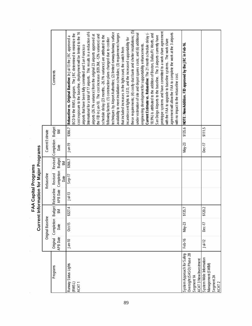
89
Prog
rams
Origi
nal
APB
Date
Comp
letion
Da
teBu
dget
$MRe
base
line
APB
Date
Revis
ed
Comp
letion
Da
te
Revis
ed
Budg
et $M
Comp
letion
Da
teBu
dget
$MCo
mmen
ts
Runw
ay S
tatus
Ligh
ts (R
WSL
)AC
AT 1
Jan-1
0Oc
t-15
$327
.4Ju
l-13
Sep-
17$3
66.7
Jun-1
9$3
66.7
Reba
selin
e vs.
Orig
inal
Base
line:
In Ju
l-13 t
he JR
C ap
prov
ed a
BCD
for th
e RW
SL p
rogr
am.
The
JRC
deter
mine
d to
minim
ize th
e co
st ex
posu
re to
the
base
line,
dep
loyme
nt wi
ll be
limite
d to
the 16
air
ports
that
have
bee
n full
y com
mitte
d an
d Sa
n Fran
cisco
Int
erna
tiona
l for a
total
of 1
7 airp
orts.
This
resu
lts in
a re
ducti
on o
f 6
airpo
rts (2
6.1%
varia
nce)
from
the o
rigina
l 23 a
irpor
ts ap
prov
ed at
the
FID
in Ja
n-10.
The
cost
incre
ase
($39.3
M, -1
2% va
rianc
e) an
d sc
hedu
le de
lay (2
3 mon
ths, -
26.1%
varia
nce)
are
attrib
uted
to the
fol
lowing
facto
rs: (1
) con
struc
tion p
lans c
hang
ed d
ue to
costl
ier
techn
iques
by A
irpor
t Auth
oritie
s; (2)
limite
d run
way/t
axiw
ay su
rface
av
ailab
ility t
o me
et ins
tallat
ion sc
hedu
les; (
3) re
quire
ment
chan
ges
that in
clude
d inc
reas
es in
the
light
coun
t, the
switc
h fro
m inc
ande
scen
t ligh
ts to
LED,
and
the in
creas
ed su
ppor
tabilit
y for
the
se re
quire
ments
; (4)
costl
y duc
t ban
k and
shelt
er in
stalla
tions
; (5)
unde
r esti
matio
n of s
ite an
d de
pot s
pare
s cos
ts; an
d (6)
addit
ional
engin
eerin
g de
velop
ment
for su
ppor
tabilit
y enh
ance
ments
. Cu
rrent
Esti
mate
vs. R
ebas
eline
: The
21 m
onth
sche
dule
delay
(-18
.9%) is
attrib
uted
to the
addit
ion o
f Bos
ton, D
allas
/Ft. W
orth,
and
San D
eigo
Airp
orts
to the
bas
eline
. Th
e 3 a
irpor
ts cu
rrentl
y hav
e pr
ototyp
e sy
stems
and
have
comm
itted
to a w
ork s
hare
agre
emen
t wi
th the
FAA
to up
grad
e to
base
line
syste
ms.
The
work
share
ag
reem
ent w
ill all
ow th
e FA
A to
comp
lete
the w
ork a
t the
3 airp
orts
with
no im
pact
to the
reba
selin
e co
st.
Syste
m Ap
proa
ch fo
r Safe
ty Ov
ersig
ht (S
ASO)
Pha
se 2B
Se
gmen
t 1A
AC
AT 3
New
Inves
tmen
t
Feb-
16Ma
y-23
$135
.7Ma
y-23
$135
.6NO
TE: N
ew A
dditi
on. F
ID ap
prov
ed b
y the
JRC
in F
eb-16
.
Syste
m W
ide In
forma
tion
Mana
geme
nt (S
WIM
) Se
gmen
t 2A
ACAT
2
Jul-1
2De
c-17
$120
.2De
c-17
$111
.5
Curre
nt Es
timate
Origi
nal B
aseli
neRe
base
line
FAA
Cap
ital P
rogr
ams
Cur
rent
Info
rmat
ion
for M
ajor
Pro
gram
s
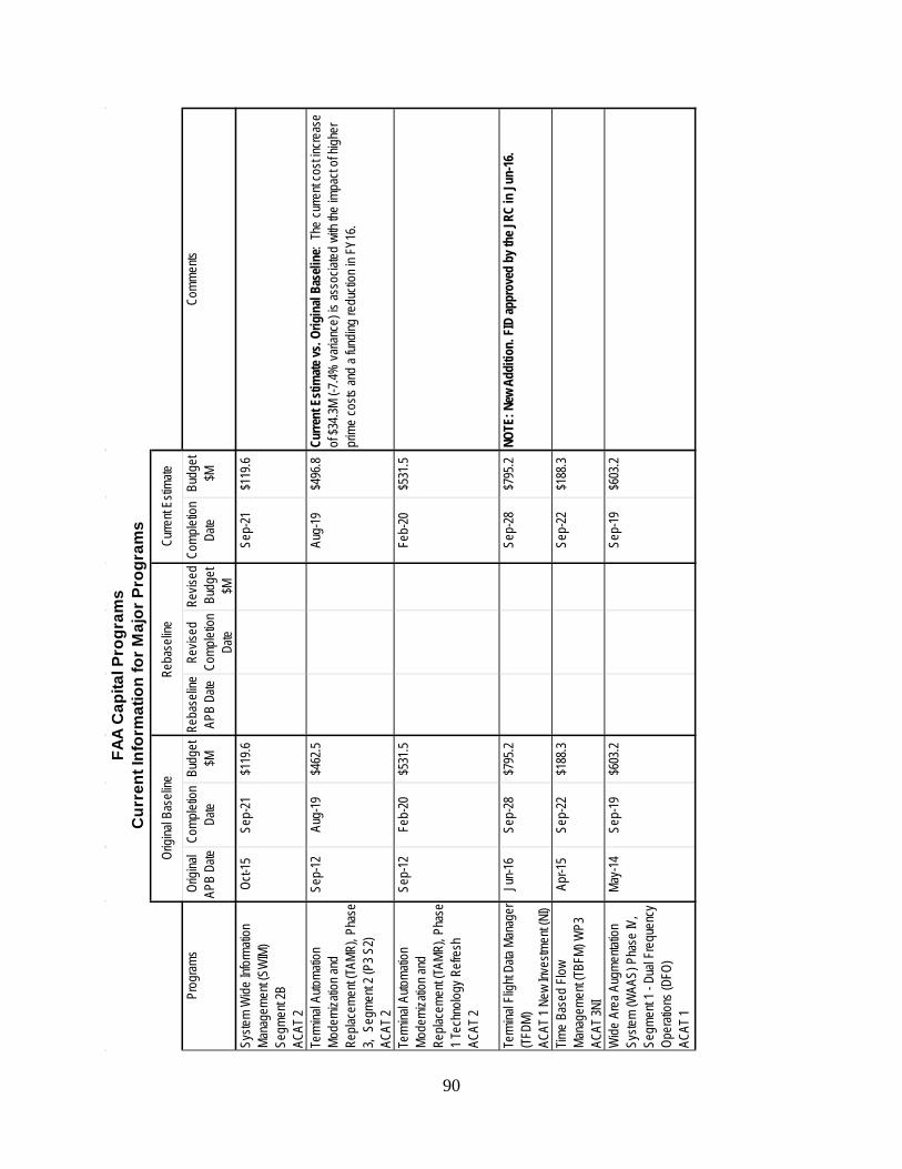
90
Prog
rams
Origi
nal
APB
Date
Comp
letion
Da
teBu
dget
$MRe
base
line
APB
Date
Revis
ed
Comp
letion
Da
te
Revis
ed
Budg
et $M
Comp
letion
Da
teBu
dget
$MCo
mmen
ts
Syste
m W
ide In
forma
tion
Mana
geme
nt (S
WIM
) Se
gmen
t 2B
ACAT
2
Oct-1
5Se
p-21
$119
.6Se
p-21
$119
.6
Term
inal A
utoma
tion
Mode
rniza
tion a
nd
Repla
ceme
nt (TA
MR),
Phas
e 3,
Seg
ment
2 (P3
S2)
ACAT
2
Sep-
12Au
g-19
$462
.5Au
g-19
$496
.8Cu
rrent
Esti
mate
vs. O
rigin
al Ba
selin
e: Th
e cu
rrent
cost
incre
ase
of $3
4.3M
(-7.4%
varia
nce)
is as
socia
ted w
ith th
e im
pact
of hig
her
prim
e co
sts an
d a f
undin
g re
ducti
on in
FY1
6.
Term
inal A
utoma
tion
Mode
rniza
tion a
nd
Repla
ceme
nt (TA
MR),
Phas
e 1 T
echn
ology
Refr
esh
ACAT
2
Sep-
12Fe
b-20
$531
.5Fe
b-20
$531
.5
Term
inal F
light
Data
Mana
ger
(TFDM
)
AC
AT 1
New
Inves
tmen
t (NI)
Jun-1
6Se
p-28
$795
.2Se
p-28
$795
.2NO
TE: N
ew A
dditi
on. F
ID ap
prov
ed b
y the
JRC
in Ju
n-16
.
Time
Base
d Flo
w Ma
nage
ment
(TBFM
) WP3
ACAT
3NI
Apr-1
5Se
p-22
$188
.3Se
p-22
$188
.3
Wide
Are
a Aug
menta
tion
Syste
m (W
AAS)
Pha
se IV
, Se
gmen
t 1 -
Dual
Freq
uenc
y Op
erati
ons (
DFO)
ACAT
1
May-1
4Se
p-19
$603
.2Se
p-19
$603
.2
Curre
nt Es
timate
Origi
nal B
aseli
neRe
base
line
FAA
Cap
ital P
rogr
ams
Cur
rent
Info
rmat
ion
for M
ajor
Pro
gram
s
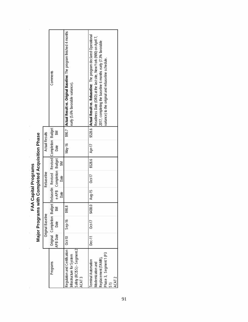
91
Prog
rams
Origi
nal
APB
Date
Comp
letion
Da
teBu
dget
$MRe
base
line
APB
Date
Revis
ed
Comp
letion
Da
te
Revis
ed
Budg
et $M
Comp
letion
Da
teBu
dget
$MCo
mmen
ts
Regu
lation
and
Certif
icatio
n Inf
rastru
cture
for S
ystem
Sa
fety (
RCIS
S) -
Segm
ent 2
ACAT
3
Oct-1
0Se
p-16
$90.8
May-1
6$9
0.7Ac
tual
Resu
lt vs
. Orig
inal
Base
line:
The
prog
ram fin
ished
4 mo
nths
early
(5.6%
favo
rable
varia
nce)
.
Term
inal A
utoma
tion
Mode
rniza
tion a
nd
Repla
ceme
nt (TA
MR),
Phas
e 3,
Seg
ment
1 (P3
S1
)AC
AT 2
Dec-1
1Oc
t-17
$438
.0Au
g-15
Oct-1
7$5
28.6
Apr-1
7$5
28.6
Actu
al Re
sult
vs. R
ebas
eline
: Th
e pr
ogram
dec
lared
Ope
ration
al Re
adine
ss D
ate (O
RD) a
t the
last s
ite, N
ew Y
ork (
N90)
on A
pril 7
, 20
17, c
omple
ting
the b
aseli
ne 6
month
s earl
y (7.3
% fa
vorab
le va
rianc
e) to
the
origi
nal a
nd re
base
line
sche
dule.
Actua
l Res
ults
Origi
nal B
aseli
neRe
base
line
FAA
Cap
ital P
rogr
ams
Maj
or P
rogr
ams
with
Com
plet
ed A
cqui
sitio
n Ph
ase
92
10 Conclusion Each year, the FAA updates and publishes the CIP to provide Congress and the public with the latest information on the plans and objectives for the capital programs over the next five years. The FY 2018-2022 CIP reflects a balanced investment approach to support continued funding for legacy equipment, facilities, systems, and services necessary to sustain current NAS infrastructure continuing modernization to NextGen. The planned funding provides the CIP programs with the appropriate resources to deliver the capabilities to meet both the current and forecast demand for aviation services in the NAS. The NAS Enterprise Architecture Roadmaps depict the legacy capital systems that support Automation, Communication, Surveillance, Navigation, and Weather. The roadmaps also show the planned CIP programs that will support these functions in the future along with the timeline for their development and future deployment if applicable. A brief description is provided for both the legacy systems and the planned CIP programs. As the FAA moves forward with the implementation of new applications using proven technologies, such as ADS-B and Data Communications, new capabilities will be deployed for improved surveillance, more efficient flight paths, and the expanded use of automated communications between controllers and pilots to execute routine commands. These technology improvements may also help to support the integration of UAS into the NAS and improve the management of airspace impacted by Commercial Space operations. The development and implementation of NextGen is well underway and adjustments to the CIP programs will be made as needed to address changes in forecasted demand; challenges with emerging technologies; and the availability of funds to complete NextGen as planned. FAA’s capital programs are on track to provide the infrastructure, capabilities, and NAS services required to complete the implementation of NextGen and deliver promised capabilities while maintaining the high level of NAS service and system safety that the aviation community and the public rely on every day.
93
11 Appendices The CIP contains two appendices. Appendix A
• Lists FAA strategic priorities and performance metrics. • Associates CIP programs with performance metrics.
Appendix B
• Provides CIP program descriptions. • Shows the selected strategic priority and performance metric for the program. • Describes the programs contribution to meeting the performance metric. • Lists performance output goals for FY 2018–2022. • Shows system implementation schedules for selected programs.
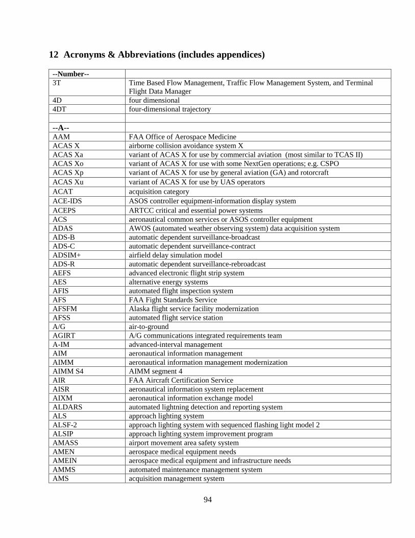
94
12 Acronyms & Abbreviations (includes appendices) --Number-- 3T Time Based Flow Management, Traffic Flow Management System, and Terminal
Flight Data Manager 4D four dimensional 4DT four-dimensional trajectory --A-- AAM FAA Office of Aerospace Medicine ACAS X airborne collision avoidance system X ACAS Xa variant of ACAS X for use by commercial aviation (most similar to TCAS II) ACAS Xo variant of ACAS X for use with some NextGen operations; e.g. CSPO ACAS Xp variant of ACAS X for use by general aviation (GA) and rotorcraft ACAS Xu variant of ACAS X for use by UAS operators ACAT acquisition category ACE-IDS ASOS controller equipment-information display system ACEPS ARTCC critical and essential power systems ACS aeronautical common services or ASOS controller equipment ADAS AWOS (automated weather observing system) data acquisition system ADS-B automatic dependent surveillance-broadcast ADS-C automatic dependent surveillance-contract ADSIM+ airfield delay simulation model ADS-R automatic dependent surveillance-rebroadcast AEFS advanced electronic flight strip system AES alternative energy systems AFIS automated flight inspection system AFS FAA Fight Standards Service AFSFM Alaska flight service facility modernization AFSS automated flight service station A/G air-to-ground AGIRT A/G communications integrated requirements team A-IM advanced-interval management AIM aeronautical information management AIMM aeronautical information management modernization AIMM S4 AIMM segment 4 AIR FAA Aircraft Certification Service AISR aeronautical information system replacement AIXM aeronautical information exchange model ALDARS automated lightning detection and reporting system ALS approach lighting system ALSF-2 approach lighting system with sequenced flashing light model 2 ALSIP approach lighting system improvement program AMASS airport movement area safety system AMEN aerospace medical equipment needs AMEIN aerospace medical equipment and infrastructure needs AMMS automated maintenance management system AMS acquisition management system
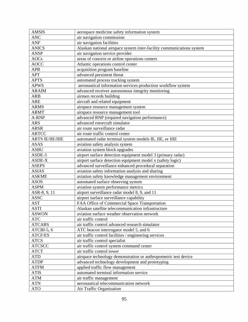
95
AMSIS aerospace medicine safety information system ANC air navigation commission ANF air navigation facilities ANICS Alaskan national airspace system inter-facility communications system ANSP air navigation service provider AOCs areas of concern or airline operations centers AOCC Atlantic operations control center APB acquisition program baseline APT advanced persistent threat APTS automated process tracking system APWS aeronautical information services production workflow system ARAIM advanced receiver autonomous integrity monitoring ARB airmen records building ARE aircraft and related equipment ARMS airspace resource management system ARMT airspace resource management tool A-RNP advanced RNP (required navigation performance) ARS advanced rotorcraft simulator ARSR air route surveillance radar ARTCC air route traffic control center ARTS IE/IIE/IIIE automated radar terminal system models IE, IIE, or IIIE ASAS aviation safety analysis system ASBU aviation system block upgrades ASDE-3 airport surface detection equipment model 3 (primary radar) ASDE-X airport surface detection equipment model x (safety logic) ASEPS advanced surveillance enhanced procedural separation ASIAS aviation safety information analysis and sharing ASKME aviation safety knowledge management environment ASOS automated surface observing system ASPM aviation system performance metrics ASR-8, 9, 11 airport surveillance radar model 8, 9, and 11 ASSC airport surface surveillance capability AST FAA Office of Commercial Space Transportation ASTI Alaskan satellite telecommunication infrastructure ASWON aviation surface weather observation network ATC air traffic control ATCARS air traffic control advanced research simulator ATCBI-5, 6 ATC beacon interrogator model 5, and 6 ATCF/ES air traffic control facilities / engineering services ATCS air traffic control specialist ATCSCC air traffic control system command center ATCT air traffic control tower ATD airspace technology demonstration or anthropometric test device ATDP advanced technology development and prototyping ATFM applied traffic flow management ATIS automated terminal information service ATM air traffic management ATN aeronautical telecommunication network ATO Air Traffic Organization
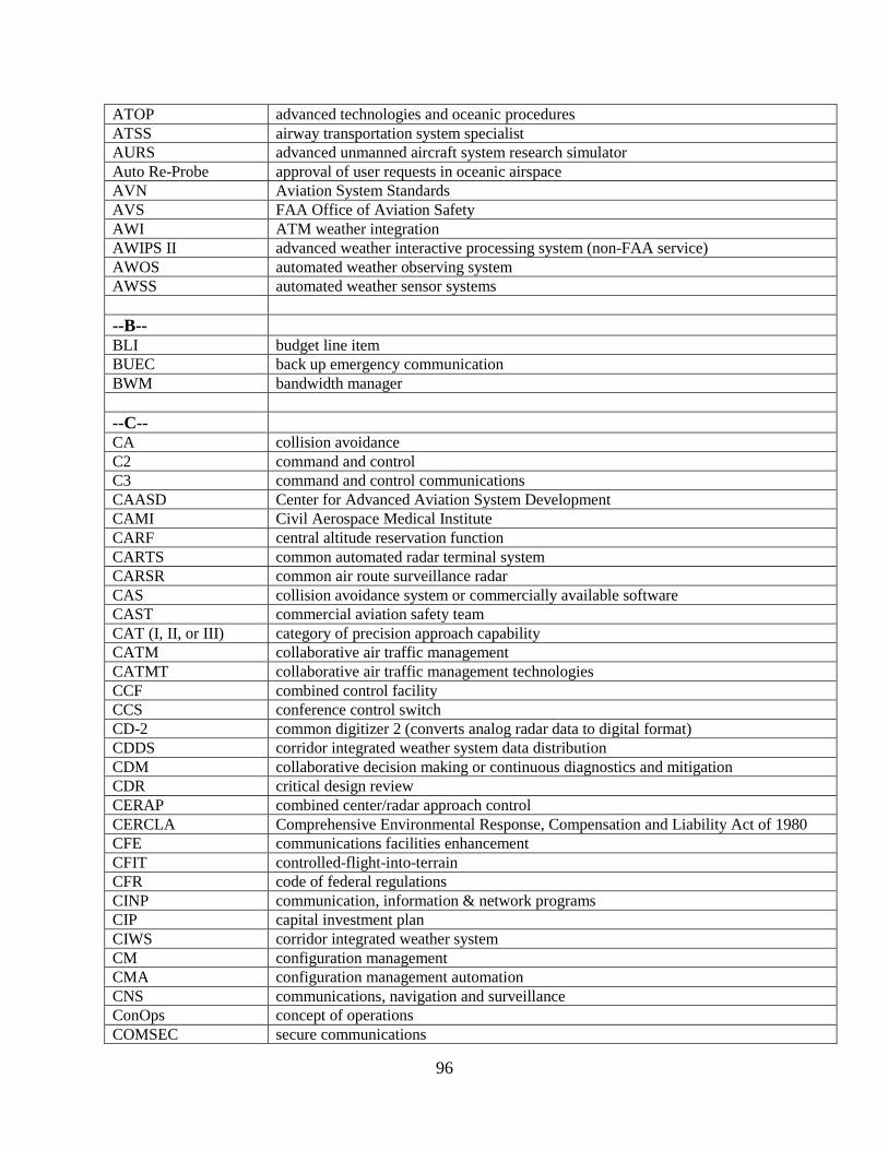
96
ATOP advanced technologies and oceanic procedures ATSS airway transportation system specialist AURS advanced unmanned aircraft system research simulator Auto Re-Probe approval of user requests in oceanic airspace AVN Aviation System Standards AVS FAA Office of Aviation Safety AWI ATM weather integration AWIPS II advanced weather interactive processing system (non-FAA service) AWOS automated weather observing system AWSS automated weather sensor systems --B-- BLI budget line item BUEC back up emergency communication BWM bandwidth manager --C-- CA collision avoidance C2 command and control C3 command and control communications CAASD Center for Advanced Aviation System Development CAMI Civil Aerospace Medical Institute CARF central altitude reservation function CARTS common automated radar terminal system CARSR common air route surveillance radar CAS collision avoidance system or commercially available software CAST commercial aviation safety team CAT (I, II, or III) category of precision approach capability CATM collaborative air traffic management CATMT collaborative air traffic management technologies CCF combined control facility CCS conference control switch CD-2 common digitizer 2 (converts analog radar data to digital format) CDDS corridor integrated weather system data distribution CDM collaborative decision making or continuous diagnostics and mitigation CDR critical design review CERAP combined center/radar approach control CERCLA Comprehensive Environmental Response, Compensation and Liability Act of 1980 CFE communications facilities enhancement CFIT controlled-flight-into-terrain CFR code of federal regulations CINP communication, information & network programs CIP capital investment plan CIWS corridor integrated weather system CM configuration management CMA configuration management automation CNS communications, navigation and surveillance ConOps concept of operations COMSEC secure communications
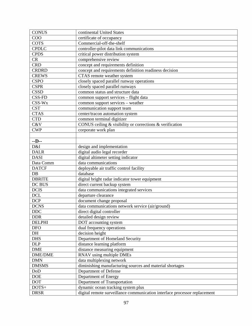
97
CONUS continental United States COO certificate of occupancy COTS Commercial-off-the-shelf CPDLC controller-pilot data link communications CPDS critical power distribution system CR comprehensive review CRD concept and requirements definition CRDRD concept and requirements definition readiness decision CREWS CTAS remote weather system CSPO closely spaced parallel runway operations CSPR closely spaced parallel runways CSSD common status and structure data CSS-FD common support services – flight data CSS-Wx common support services – weather CST communication support team CTAS center/tracon automation system CTD common terminal digitizer C&V CONUS ceiling & visibility or corrections & verification CWP corporate work plan --D-- D&I design and implementation DALR digital audio legal recorder DASI digital altimeter setting indicator Data Comm data communications DATCF deployable air traffic control facility DB database DBRITE digital bright radar indicator tower equipment DC BUS direct current backup system DCIS data communications integrated services DCL departure clearance DCP document change proposal DCNS data communications network service (air/ground) DDC direct digital controller DDR detailed design review DELPHI DOT accounting system DFO dual frequency operations DH decision height DHS Department of Homeland Security DLP distance learning platform DME distance measuring equipment DME/DME RNAV using multiple DMEs DMN data multiplexing network DMSMS diminishing manufacturing sources and material shortages DoD Department of Defense DOE Department of Energy DOT Department of Transportation DOTS+ dynamic ocean tracking system plus DRSR digital remote surveillance communication interface processor replacement
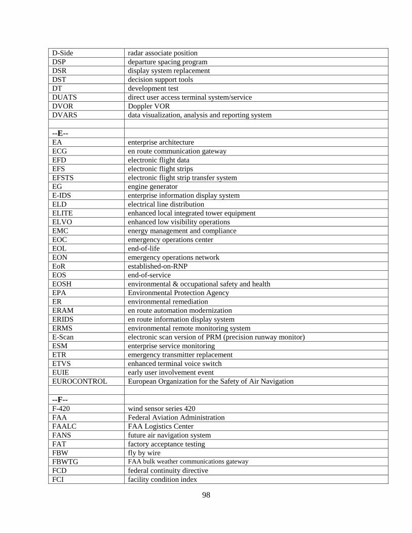
98
D-Side radar associate position DSP departure spacing program DSR display system replacement DST decision support tools DT development test DUATS direct user access terminal system/service DVOR Doppler VOR DVARS data visualization, analysis and reporting system --E-- EA enterprise architecture ECG en route communication gateway EFD electronic flight data EFS electronic flight strips EFSTS electronic flight strip transfer system EG engine generator E-IDS enterprise information display system ELD electrical line distribution ELITE enhanced local integrated tower equipment ELVO enhanced low visibility operations EMC energy management and compliance EOC emergency operations center EOL end-of-life EON emergency operations network EoR established-on-RNP EOS end-of-service EOSH environmental & occupational safety and health EPA Environmental Protection Agency ER environmental remediation ERAM en route automation modernization ERIDS en route information display system ERMS environmental remote monitoring system E-Scan electronic scan version of PRM (precision runway monitor) ESM enterprise service monitoring ETR emergency transmitter replacement ETVS enhanced terminal voice switch EUIE early user involvement event EUROCONTROL European Organization for the Safety of Air Navigation --F-- F-420 wind sensor series 420 FAA Federal Aviation Administration FAALC FAA Logistics Center FANS future air navigation system FAT factory acceptance testing FBW fly by wire FBWTG FAA bulk weather communications gateway FCD federal continuity directive FCI facility condition index

99
FCT federal contract tower FDCS flight data common service FDIO flight data input/output FDP flight data processor FDP2K flight data processing 2000 F&E facilities and equipment FF-ICE flight and flow integrated collaborative environment FFRDC federally funded research and development center FFSP future flight service program FI flight inspection FID final investment decision FIM flight interval management FIS-B flight information services – broadcast FIXM flight information exchange model FLS fire life safety FMC flight management computer FMS flight management system FNS federal NOTAM system FOC flight operations center or final operational capability FOXS flight object exchange service FSRM facility security risk management FSS flight service station FST fuel storage tank FTB Florida NextGen test bed FTE full time equivalent FTI FAA telecommunications infrastructure FTI-2 successor program to FTI FY fiscal year --G-- GA general aviation GAO Government Accountability Office GATTOR general air traffic and technical operations research GDP gross domestic product GEO geostationary satellite GIM-S ground based interval management-spacing GIS geographic information system GLS ground based augmentation landing system GNAS general national air space system GNSS global navigation satellite system or service GOM Gulf of Mexico GPS global positioning system GSA General Services Administration GTG graphical turbulence guidance GUI graphical user interface --H-- HADDS HOST ATM data distribution system

100
HAZMAT hazardous materials HF high frequency or human factors HGOPA high gain open planar array HITL human-in-the-loop HOST Host Computer System HP high power HPSB high performance sustainable building HRRR high resolution rapid refresh HUD heads up display HVAC heating, ventilating and air conditioning --I-- IAM identity and access management IARD investment analysis readiness decision ICAO International Civil Aviation Organization ICCT Interagency Core Cyber Team ICMS Interlock control and monitoring system ICSS integrated communication switching system IDAC integrated departure/arrival capability IDLM interference detection, location and mitigation IDP improved demand predictions IDRP integrated departure route planning IDS integrated display system IESP integrated enterprise service platform IFP instrument flight procedures IFPA instrument flight procedures automation IFR instrument flight rules IID initial investment decision ILS (I, II, or III) instrument landing system (category I, II, or III) IM interval management IMC instrument meteorological conditions INDP integrated NAS design and procedure planning IOA independent operational assessment IOC initial operating capability IP internet protocol IPDS instrument procedure development system IPS internet protocol suite IRU inertial reference unit ISAM integrated safety assessment model ISD in-service decision ISO International Standards Organization ISPD implementation strategy and planning document ISS information system security IT information technology ITWS integrated terminal weather system IVSR interim voice switch replacement --J--

101
JAWS Juneau airport wind system JRC joint resources council
--K-- KVM kinetic vertical modeling or keyboard video mouse
--L-- L1 C/A GPS legacy civil frequency L5 GPS second civil frequency L1/L5 GPS dual frequency for WAAS users LAHSO land and hold short operations LAN local area network LCSS logistics center support system LDIN lead in light system LDRCL low-density radio communication link LIDAR light detection and ranging LITE local integrated tower equipment LLWAS low-level wind shear alert system LOC localizer LP localizer performance or low power LPGBS lightning protection, grounding, bonding, and shielding LPV localizer performance with vertical guidance LRR long range radar LRUs lowest replaceable units LSS logistics support services LSSF logistics support system and facilities LVO low visibility operations --M-- MALSR medium-intensity approach light system with runway alignment indicator lights MAMP mobile asset management program MASA mobile asset staging area MASR mobile airport surveillance radar MATCT mobile air traffic control tower MB marker beacons MDR multimode digital radios mDAS miniature data acquisition system METP ICAO meteorology panel mGC micro gas chromatograph Micro-EARTS microprocessor en route automated radar tracking system MIT/LL Massachusetts Institute of Technology Lincoln Laboratory MMAC Mike Monroney Aeronautical Center MOCC mid-states operations control center Mode S mode select MON minimum operational network MOPS minimum operational performance standards MSN message switching network

102
--N-- NADIN MSN national airspace data interchange network – message switching network NADIN PSN national airspace data interchange network – package switching network NAFIS next generation automated flight inspection system NAIMES NAS aeronautical information enterprise system NARP national aviation research plan NAS national airspace system NASA National Aeronautics and Space Administration NASE NAS adaptation services environment NAS EA NAS enterprise architecture NASR national airspace system resources Navaids navigation aids Nav Lean navigation procedures implementation plan NBSC NextGen backup surveillance capability NCR NAS common reference NDB non-directional beacon NEB NextGen executive board NEMC network enterprise management center NEMS NAS enterprise messaging service NEWP Nextgen executive weather panel NEXCOM next generation air/ground communications NEXRAD next generation weather radar NextGen next generation air transportation system NIDS NAS information display system NIEC NextGen integration and evaluation capability NISC NAS integration support contract NG new generation RVR NLN national logging network NM nautical mile (6,076 ft.) NME navaids monitoring equipment NOAA National Oceanic and Atmospheric Administration NOCC national operations control center NOP national offload program NOTAM notices to airmen NPI NEXRAD product improvement NPS NextGen performance snapshots NRN national remote maintenance monitoring network NSG navigation service group NSIP NAS segment implementation plan NSWRC next generation surveillance and weather radar capability NTEP national test equipment program NTSB National Transportation Safety Board NVR NAS voice recorder NVRP NAS voice recorder program NVS national airspace system voice system NWP NextGen weather processor NWS National Weather Service
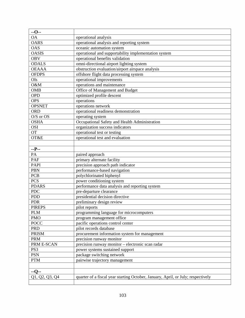
103
--O-- OA operational analysis OARS operational analysis and reporting system OAS oceanic automation system OASIS operational and supportability implementation system OBV operational benefits validation ODALS omni-directional airport lighting system OEAAA obstruction evaluation/airport airspace analysis OFDPS offshore flight data processing system OIs operational improvements O&M operations and maintenance OMB Office of Management and Budget OPD optimized profile descent OPS operations OPSNET operations network ORD operational readiness demonstration O/S or OS operating system OSHA Occupational Safety and Health Administration OSI organization success indicators OT operational test or testing OT&E operational test and evaluation
--P-- PA paired approach PAF primary alternate facility PAPI precision approach path indicator PBN performance-based navigation PCB polychlorinated biphenyl PCS power conditioning system PDARS performance data analysis and reporting system PDC pre-departure clearance PDD presidential decision directive PDR preliminary design review PIREPS pilot reports PLM programming language for microcomputers PMO program management office POCC pacific operations control center PRD pilot records database PRISM procurement information system for management PRM precision runway monitor PRM E-SCAN precision runway monitor – electronic scan radar PS3 power systems sustained support PSN package switching network PTM pairwise trajectory management
--Q-- Q1, Q2, Q3, Q4 quarter of a fiscal year starting October, January, April, or July; respectively
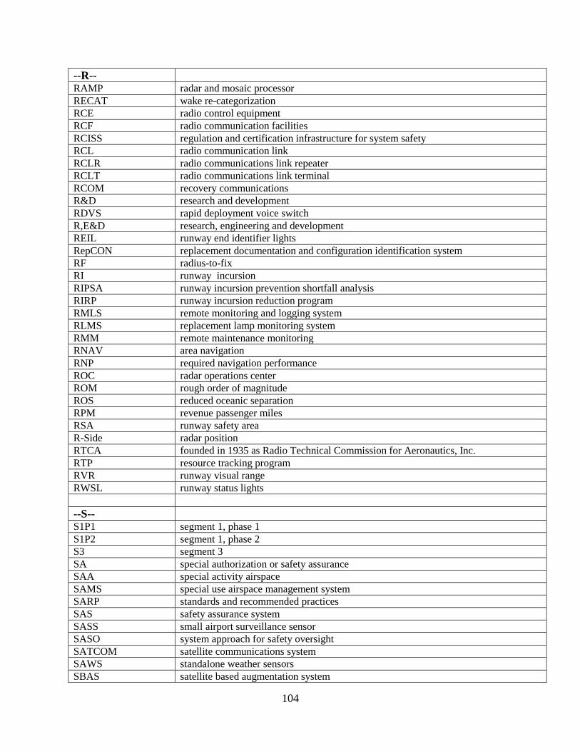
104
--R-- RAMP radar and mosaic processor RECAT wake re-categorization RCE radio control equipment RCF radio communication facilities RCISS regulation and certification infrastructure for system safety RCL radio communication link RCLR radio communications link repeater RCLT radio communications link terminal RCOM recovery communications R&D research and development RDVS rapid deployment voice switch R,E&D research, engineering and development REIL runway end identifier lights RepCON replacement documentation and configuration identification system RF radius-to-fix RI runway incursion RIPSA runway incursion prevention shortfall analysis RIRP runway incursion reduction program RMLS remote monitoring and logging system RLMS replacement lamp monitoring system RMM remote maintenance monitoring RNAV area navigation RNP required navigation performance ROC radar operations center ROM rough order of magnitude ROS reduced oceanic separation RPM revenue passenger miles RSA runway safety area R-Side radar position RTCA founded in 1935 as Radio Technical Commission for Aeronautics, Inc. RTP resource tracking program RVR runway visual range RWSL runway status lights --S-- S1P1 segment 1, phase 1 S1P2 segment 1, phase 2 S3 segment 3 SA special authorization or safety assurance SAA special activity airspace SAMS special use airspace management system SARP standards and recommended practices SAS safety assurance system SASS small airport surveillance sensor SASO system approach for safety oversight SATCOM satellite communications system SAWS standalone weather sensors SBAS satellite based augmentation system
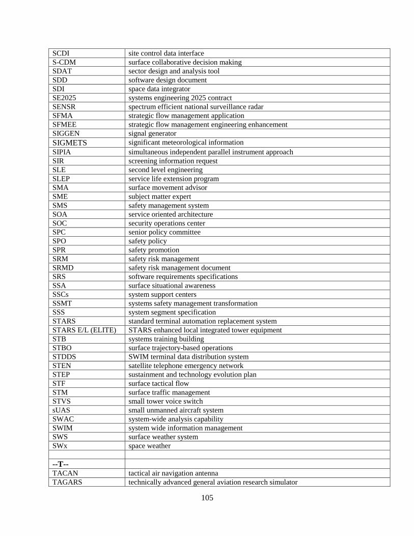
105
SCDI site control data interface S-CDM surface collaborative decision making SDAT sector design and analysis tool SDD software design document SDI space data integrator SE2025 systems engineering 2025 contract SENSR spectrum efficient national surveillance radar SFMA strategic flow management application SFMEE strategic flow management engineering enhancement SIGGEN signal generator SIGMETS significant meteorological information SIPIA simultaneous independent parallel instrument approach SIR screening information request SLE second level engineering SLEP service life extension program SMA surface movement advisor SME subject matter expert SMS safety management system SOA service oriented architecture SOC security operations center SPC senior policy committee SPO safety policy SPR safety promotion SRM safety risk management SRMD safety risk management document SRS software requirements specifications SSA surface situational awareness SSCs system support centers SSMT systems safety management transformation SSS system segment specification STARS standard terminal automation replacement system STARS E/L (ELITE) STARS enhanced local integrated tower equipment STB systems training building STBO surface trajectory-based operations STDDS SWIM terminal data distribution system STEN satellite telephone emergency network STEP sustainment and technology evolution plan STF surface tactical flow STM surface traffic management STVS small tower voice switch sUAS small unmanned aircraft system SWAC system-wide analysis capability SWIM system wide information management SWS surface weather system SWx space weather --T-- TACAN tactical air navigation antenna TAGARS technically advanced general aviation research simulator
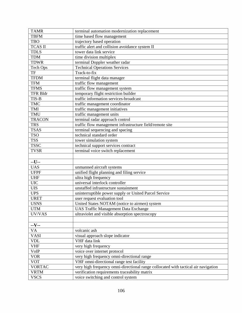
106
TAMR terminal automation modernization replacement TBFM time based flow management TBO trajectory based operation TCAS II traffic alert and collision avoidance system II TDLS tower data link service TDM time division multiplex TDWR terminal Doppler weather radar Tech Ops Technical Operations Services TF Track-to-fix TFDM terminal flight data manager TFM traffic flow management TFMS traffic flow management system TFR Bldr temporary flight restriction builder TIS-B traffic information services-broadcast TMC traffic management coordinator TMI traffic management initiatives TMU traffic management units TRACON terminal radar approach control TRS traffic flow management infrastructure field/remote site TSAS terminal sequencing and spacing TSO technical standard order TSS tower simulation system TSSC technical support services contract TVSR terminal voice switch replacement
--U-- UAS unmanned aircraft systems UFPF unified flight planning and filing service UHF ultra high frequency UIC universal interlock controller UIS unstaffed infrastructure sustainment UPS uninterruptible power supply or United Parcel Service URET user request evaluation tool USNS United States NOTAM (notice to airmen) system UTM UAS Traffic Management Data Exchange UV/VAS ultraviolet and visible absorption spectroscopy
--V-- VA volcanic ash VASI visual approach slope indicator VDL VHF data link VHF very high frequency VoIP voice over internet protocol VOR very high frequency omni-directional range VOT VHF omni-directional range test facility VORTAC very high frequency omni-directional range collocated with tactical air navigation VRTM verification requirements traceability matrix VSCS voice switching and control system
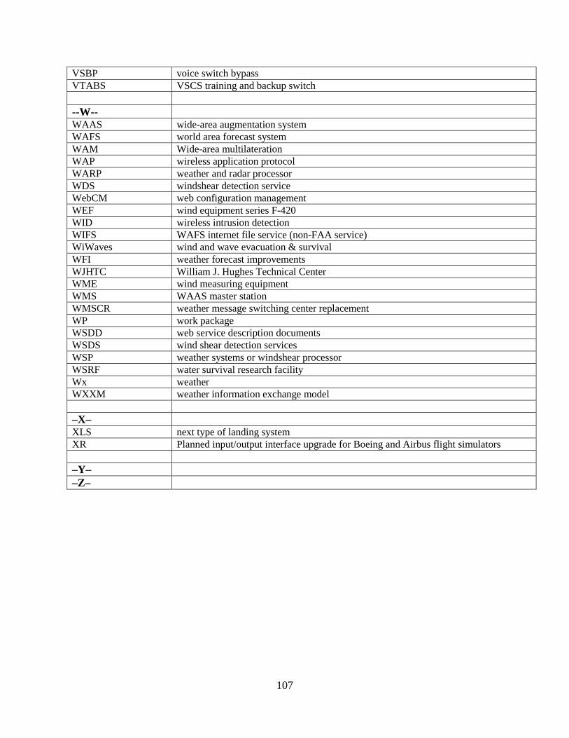
107
VSBP voice switch bypass VTABS VSCS training and backup switch
--W-- WAAS wide-area augmentation system WAFS world area forecast system WAM Wide-area multilateration WAP wireless application protocol WARP weather and radar processor WDS windshear detection service WebCM web configuration management WEF wind equipment series F-420 WID wireless intrusion detection WIFS WAFS internet file service (non-FAA service) WiWaves wind and wave evacuation & survival WFI weather forecast improvements WJHTC William J. Hughes Technical Center WME wind measuring equipment WMS WAAS master station WMSCR weather message switching center replacement WP work package WSDD web service description documents WSDS wind shear detection services WSP weather systems or windshear processor WSRF water survival research facility Wx weather WXXM weather information exchange model –X– XLS next type of landing system XR Planned input/output interface upgrade for Boeing and Airbus flight simulators –Y– –Z–