introduction of ahci test tool - ulink...
TRANSCRIPT
WHITE PAPER ULINK Technology
INTRODUCTION OF AHCI TEST TOOL: DRIVE MASTER PRO 2004 – AHCI EDITION
A SOFTWARE TOOL FOR VALIDATING AHCI DESIGN AND PROMOTING AHCI TECHNOLOGY By Yun Wang April 28, 2004
Background The host interface to the storage devices has come a long way. In the early days when IBM initially designed the PC-XT, the storage was based on the old SASI type of interface built around the IO registers. The SASI has evolved into the SCSI standard that is popular today. After IBM started its PC-AT design, it chose the register based “Task File” interface for command and data delivery. This interface has been used and improved for the past 20 years in the PC system as the major storage interface. Although the interface has been modified for better performance and more sophistication, the basic architecture still remains the same: a Task File interface is used for the command delivery and data transfer. SATA interface is built on the foundation of this Task File architecture. This serial protocol has made its efforts to emulate the Task File interface, and delivery data via serial packets. The success of the SATA interface has brought the storage device toward a newer and higher performance stage. The transfer speed is doubled and will be triple in the next few years to come. The reliability has increased by the using of the serial packet transport mechanism with CRC protection on each transfer frame. And the compatibility of the software and hardware has made the transition from PATA to SATA less of an issue. However as the system demands higher performance from the storage device, the Task File architecture has run into its limitation, just as the PATA connection has reached its electrical limitation. The problem is Task File was built on a single command rather than multiple command execution structure, or “command queuing.”
Copyright@2004 ULINK Technology, Inc. Page 1
The Challenge Building on the SATA innovation, PC storage devices are starting to embrace the performance improvement of command queuing. Command queuing is not a new concept for storage devices. When the scientist studies the rotational device, it became obvious that the latency and physical track movement are the major performance obstacles. In the early time SCSI has added disconnect and reconnect features into its basic protocol. While it is lagging in the ATA, SCSI has quickly established its performance leadership by designing and adopting the command queuing structure. This, along with the error reporting structure, has made the SCSI the choice of storage device in many high-end systems. With the advanced architecture leaded by Intel, the SATA group quickly defined the First Party DMA command, also known as NCQ (Native Command Queuing). NCQ allows systems to take advantage of a queuing structure in the SATA interface. It lets device to reorder multiple commands in order to minimize the rotational latency and track access overhead. By adding this feature, SATA can show a comparable performance with SCSI. The Task File architecture, which has brought ATA many years of success, has also become a major obstacle. People want something better than Task File to deliver commands that current Task File can not possibly support.* (Task File is designed to handle single command at a time. When using its overlap feature, AKA TCQ (Tag Command Queuing), host CPU needs to spend many cycles taking care of the protocol handshake because of its complicated interrupt handling. As a result the implementation becomes less desirable for most of system designers.) What is the solution? There are, in fact, many approaches that can be considered. The HBA people have been providing their proprietary interface supports for a long time. They had improved the Task File structure for command handling and for RAID applications. Many of them can be used for supporting NCQ command delivery.. While most people are focused on a solution for how to design hardware, software driver is the most important key element to be considered. The major success story for the ATA interface is its software compatibility. The Task File may not be the best mechanism to deliver command and data, but it runs on many machine’s BIOS and device drivers. So the challenge is not only to design an interface to deliver the NCQ protocol, but also to make software, device driver development and debugging less of a pain.
The Solution AHCI is a host system interface designed for this purpose: to support NCQ and to provide a platform for hardware and software vendors to use. Intel has leaded the industry to define a NEW TASK FILE: AHCI for the next generation of storage interface. It prepares a command base for hardware vendors and software drivers to build a higher
Copyright@2004 ULINK Technology, Inc. Page 2
performance storage interface. It also allows vendors to add additional enhancement while keeping the core architecture compatible. The present state of AHCI can be an extension to the Task File architecture defined 20 years ago.
The Value of the Test Tool ULINK has developed a program specifically used for testing AHCI. ULINK believes its tool will provide many benefits to the industry, functioning as:
1. AHCI Compliance Test Software 2. AHCI Hardware and Protocol Debug Tool 3. AHCI Traffic Generator for Device Interface Test
AHCI Compliance Test Compliance test is required for every protocol implementation. Using a system tool such as Windows file copy and compare can achieve very limited validation. Many issues should be resolved in an early stage using a command based test tool. The tool provides utility for the user to walk though every command and protocol supported. ULINK believes that the AHCI tool can help the system house and the HBA designer to debug the chip. This will save many silicon revisions by testing the implementation thoroughly and in its early system bring-up.
AHCI Protocol Debug In addition, a proper tool can help user debug and find the problems more easily. The user-friendly interface with register editing and testing as well as validation of the transport protocol can help the designers find problems more easily. This will save the total system development time and guarantee the success of major investment from the system company. Software designed with powerful GUI and scripting capability can be a key to the time/schedule competitive product delivery.
AHCI Traffic Generator Because of the complicated queuing system and advanced SATA feature, the debugger of the host interface must be able to decipher all of the complicated traffic and review the result from the test. Issuing commands is only the first step of system validation, the complexity comes when deciding how many different combinations of commands, corner cases, and error conditions have to be verified. By providing the AHCI test tool, ULINK delivers consistent, repeatable, automated, and comprehensive solution for the industry.
Copyright@2004 ULINK Technology, Inc. Page 3
ULINK provides basic test scripts for users to get started. After using the tool, engineers can add their special needs into the scripts. Because of its flexibility in scripting, the user will add their intellective property to the test, and the return of the investment can be secured. Because of the automation of script execution, user no longer needs to type in the test manually. The test designed by the engineers can be executed repeatedly and reliably by the scripts. Every corrective action can be verified on every hardware revision.
The Platform: Drive Master 2004 – AHCI Edition Building on the popular Microsoft Windows platform, the Drive Master AHCI Edition brings all the benefits from its powerful user interface and logging capabilities. The platform is built on the following foundations:
1. Interactive AHCI Register Window 2. Manual Command Activation 3. Ball-of-Wax AHCI Validation
The following sections describe these functions in detail.
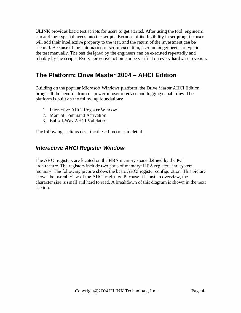
Interactive AHCI Register Window The AHCI registers are located on the HBA memory space defined by the PCI architecture. The registers include two parts of memory: HBA registers and system memory. The following picture shows the basic AHCI register configuration. This picture shows the overall view of the AHCI registers. Because it is just an overview, the character size is small and hard to read. A breakdown of this diagram is shown in the next section.
Copyright@2004 ULINK Technology, Inc. Page 4
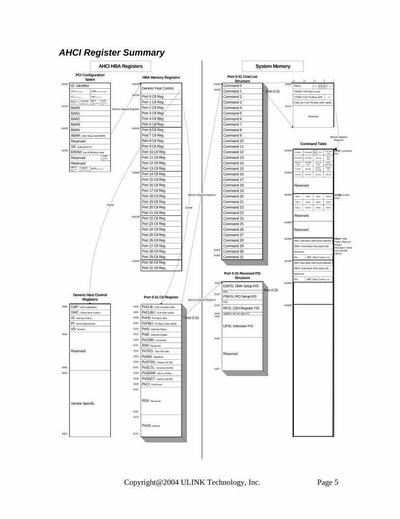
AHCI Register Summary
0x00A0
0x00A0
0x0090
0x0060
0x0040
0x0010
0x0000
0x0080
0x000
0x010
0x020
0x030
0x0100
0x1000
0x0800
0x0C00
0x0100
0x000031 23 15 7
0x010
0x000
0x020
0x000
0x3C0
0x3E0
0xA0
0x00
0x20
0x40
0x580x60
0xFF
00A0
009C
00FC
0100
0104
0108
010C
0110
0114
0118
011C
0120
0124
0128
012C
0130
0134
0138
013C
016C
0170
017C
0020
0000
Generic Host Control
HTYPE: Header Type
PCI Configuration Space
Port 0 Ctl RegPort 1 Ctl RegPort 2 Ctl RegPort 3 Ctl RegPort 4 Ctl RegPort 5 Ctl RegPort 6 Ctl RegPort 7 Ctl RegPort 8 Ctl RegPort 9 Ctl RegPort 10 Ctl RegPort 11 Ctl RegPort 12 Ctl RegPort 13 Ctl RegPort 14 Ctl RegPort 15 Ctl RegPort 16 Ctl RegPort 17 Ctl RegPort 18 Ctl RegPort 19 Ctl RegPort 20 Ctl RegPort 21 Ctl RegPort 22 Ctl RegPort 23 Ctl RegPort 24 Ctl RegPort 25 Ctl RegPort 26 Ctl RegPort 27 Ctl RegPort 28 Ctl RegPort 29 Ctl RegPort 30 Ctl RegPort 31 Ctl Reg
Memory Mapped Registers
AHCI HBA Registers System Memory
Command 0Command 1 Command 2 Command 3 Command 4 Command 5 Command 6 Command 7 Command 8 Command 9 Command 10 Command 11 Command 12 Command 13 Command 14 Command 15 Command 16 Command 17 Command 18 Command 19 Command 20 Command 21 Command 22 Command 23 Command 24 Command 25 Command 26 Command 27 Command 28 Command 29 Command 30 Command 31
Memory Mapped Registers
Port 0-31 Cmd List Structure
DSFIS: DMA Setup FIS
Port 0-31 Received FIS Structure
PSFIS: PIO Setup FIS
RFIS: D2H Register FIS
UFIS: Unknown FIS
Memory Mapped Registers
Port 0-31
Port 0-31
Reserved
HBA Memory Registers
Command Table
ID: IdentifierCMD: Command RegisterSTS: Device Status
RID: Revision IDCC: Class Code
CLS: Cache Line Size
MLT: Master Latency Timer
BIST: Built In Self Test
BAR0BAR1BAR2BAR3BAR4ABAR: AHCI Base Addr BAR5
SS: Subsystem ID
EROM: Exp ROM Base AddrCAP: Capability Ptr
INTR: Interrupt InfoMGNT: Min Grant (Opt)
MLAT: Max Latency (Opt)
CAP: Host Capabilities
GHC: Global Host Control
IS: Interrupt Status
PI: Ports Implemented
VS: Version
Generic Host Control Registers
Reserved
Vendor Specific
PxCLB: Cmd List Base Addr
PxCLBU: CLB Addr Up32b
PxFB: FIS Base Addr
PxFBU: FIS Base Addr Up32b
PxIS: Interrupt Status
Port 0-31 Ctl Register
PxIE: Interrupt Enable
PxCMD: Command
RSV: Reserved
PxTFD: Task File Data
PxSIG: Signature
PxSTSS: SStatus (SCR0)
PxSCTL: SControl (SCR2)
PxSERR: SError (SCR1)
PxSACT: SActive (SCR3)
PxCI: Cmd Issue
RSV: Reserved
PxVS: Version
Port 0-31SDBFIS: Set Dev Bits FIS
Reserved
RSV
RSV
PRDTL
PRDBC: PRD Byte Count
CTBA0: Cmd Tbl Base Addr
CTBA_U0: Cmd Tbl Base Addr Up32b
PMP R RBC P WA CFA
RSV
Reserved
Memory Mapped RegistersReserved
ReservedReserved
FIS Type (27)RsvCommandFeatures
CFIS: Command FIS
Sector NumCyl LowCyl HighDev/Head
Sector Num Exp
Cyl Low Exp
Cyl High Exp
Features Exp
Sector Cnt
Sector Cnt ExpRsv (0)Control
Reserved
Rsv (0) Rsv (0)
Byte1
Rsv (0)
Byte0Byte2
Rsv (0)
Byte3
Byte4Byte5Byte6Byte7
Byte8Byte9Byte10Byte11
Reserved
ACMD: ATAPI Cmd
PRDT: PRD Table, (Physical Region Descriptor Table) Up to 65,536 entries
DBA: Data Base Addr (word aligned)
DBAU: Data Base Addr Upper 32b
Reserved
DBC: Byte Count [21:00]Rsv 1
0
DBA: Data Base Addr (word aligned)
DBAU: Data Base Addr Upper 32b
Reserved
DBC: Byte Count [21:00]Rsv 1
0
C R R
DetailsDetails
Copyright@2004 ULINK Technology, Inc. Page 5
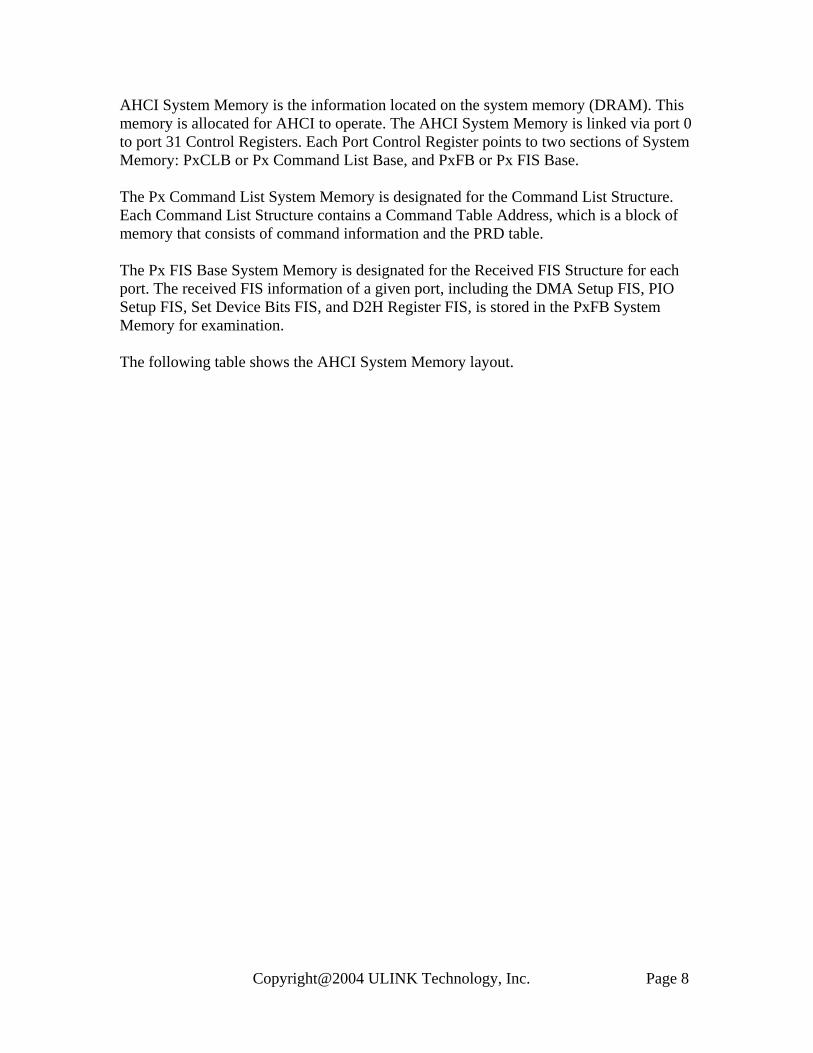
The AHCI HBA Registers are the AHCI on-board register; they are located inside the HBA controller. The AHCI HBA Registers are separated into two parts: AHCI PCI Configuration Space Registers and HBA Memory Registers. AHCI PCI Configuration Space Registers are standard PCI registers defined in the PCI Bus architecture. The HBA Memory Registers are for the Generic Host Control and Port Control, and they are linked by the ABAR (AHCI BAR), or BAR5 (Base Address Register) of the PCI Configuration Space Register. The following picture shows the details of the AHCI HBA Registers.
Copyright@2004 ULINK Technology, Inc. Page 6

Memory Mapped Registers
AHCI HBA Registers
0x000
0x010
0x020
0x030
HTYPE: Header Type
PCI Configuration Space
ID: IdentifierCMD: Command RegisterSTS: Device Status
RID: Revision IDCC: Class Code
CLS: Cache Line Size
MLT: Master Latency Timer
BIST: Built In Self Test
BAR0BAR1BAR2BAR3BAR4ABAR: AHCI Base Addr BAR5
SS: Subsystem ID
EROM: Exp ROM Base AddrCAP: Capability Ptr
INTR: Interrupt InfoMGNT: Min Grant (Opt)
MLAT: Max Latency (Opt)
Reserved
ReservedReserved
0x0100
0x1000
0x0800
0x0C00
0x0100
0x0000
Generic Host Control
Port 0 Ctl RegPort 1 Ctl RegPort 2 Ctl RegPort 3 Ctl RegPort 4 Ctl RegPort 5 Ctl RegPort 6 Ctl RegPort 7 Ctl RegPort 8 Ctl RegPort 9 Ctl RegPort 10 Ctl RegPort 11 Ctl RegPort 12 Ctl RegPort 13 Ctl RegPort 14 Ctl RegPort 15 Ctl RegPort 16 Ctl RegPort 17 Ctl RegPort 18 Ctl RegPort 19 Ctl RegPort 20 Ctl RegPort 21 Ctl RegPort 22 Ctl RegPort 23 Ctl RegPort 24 Ctl RegPort 25 Ctl RegPort 26 Ctl RegPort 27 Ctl RegPort 28 Ctl RegPort 29 Ctl RegPort 30 Ctl RegPort 31 Ctl Reg
HBA Memory Registers
00A0
009C
00FC
0020
0000 CAP: Host Capabilities
GHC: Global Host Control
IS: Interrupt Status
PI: Ports Implemented
VS: Version
Generic Host Control Registers
Reserved
Vendor Specific
Details
0100
0104
0108
010C
0110
0114
0118
011C
0120
0124
0128
012C
0130
0134
0138
013C
016C
0170
017C
PxCLB: Cmd List Base Addr
PxCLBU: CLB Addr Up32b
PxFB: FIS Base Addr
PxFBU: FIS Base Addr Up32b
PxIS: Interrupt Status
Port 0-31 Ctl Register
PxIE: Interrupt Enable
PxCMD: Command
RSV: Reserved
PxTFD: Task File Data
PxSIG: Signature
PxSTSS: SStatus (SCR0)
PxSCTL: SControl (SCR2)
PxSERR: SError (SCR1)
PxSACT: SActive (SCR3)
PxCI: Cmd Issue
RSV: Reserved
PxVS: Version
Port 0-31
Details
Copyright@2004 ULINK Technology, Inc. Page 7
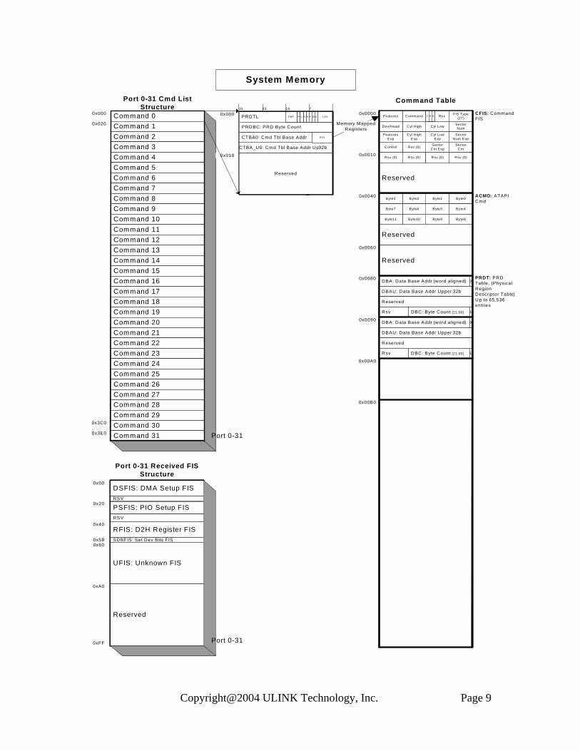
AHCI System Memory is the information located on the system memory (DRAM). This memory is allocated for AHCI to operate. The AHCI System Memory is linked via port 0 to port 31 Control Registers. Each Port Control Register points to two sections of System Memory: PxCLB or Px Command List Base, and PxFB or Px FIS Base. The Px Command List System Memory is designated for the Command List Structure. Each Command List Structure contains a Command Table Address, which is a block of memory that consists of command information and the PRD table. The Px FIS Base System Memory is designated for the Received FIS Structure for each port. The received FIS information of a given port, including the DMA Setup FIS, PIO Setup FIS, Set Device Bits FIS, and D2H Register FIS, is stored in the PxFB System Memory for examination. The following table shows the AHCI System Memory layout.
Copyright@2004 ULINK Technology, Inc. Page 8
System Memory
Memory Mapped Registers
0x020
0x000
0x3C0
0x3E0
Command 0Command 1 Command 2 Command 3 Command 4 Command 5 Command 6 Command 7 Command 8 Command 9 Command 10 Command 11 Command 12 Command 13 Command 14 Command 15 Command 16 Command 17 Command 18 Command 19 Command 20 Command 21 Command 22 Command 23 Command 24 Command 25 Command 26 Command 27 Command 28 Command 29 Command 30 Command 31
Port 0-31 Cmd List Structure
Port 0-31
0x010
31 23 15 7
0x000 PRDTL
PRDBC: PRD Byte Count
CTBA0: Cmd Tbl Base Addr
CTBA_U0: Cmd Tbl Base Addr Up32b
PMP R RBC P W A CFA
RSV
Reserved
0xA0
0x00
0x20
0x40
0x580x60
0xFF
DSFIS: DMA Setup FIS
Port 0-31 Received FIS Structure
PSFIS: PIO Setup FIS
RFIS: D2H Register FIS
UFIS: Unknown FIS
Port 0-31
SDBFIS: Set Dev Bits FIS
Reserved
RSV
RSV
0x00B0
0x00A0
0x0090
0x0060
0x0040
0x0010
0x0000
0x0080
Reserved
Command Table
FIS Type (27)RsvCommandFeatures
CFIS: Command FIS
Sector NumCyl LowCyl HighDev/Head
Sector Num Exp
Cyl Low Exp
Cyl High Exp
Features Exp
Sector Cnt
Sector Cnt ExpRsv (0)Control
Reserved
Rsv (0) Rsv (0)
Byte1
Rsv (0)
Byte0Byte2
Rsv (0)
Byte3
Byte4Byte5Byte6Byte7
Byte8Byte9Byte10Byte11
Reserved
ACMD: ATAPI Cmd
PRDT: PRD Table, (Physical Region Descriptor Table) Up to 65,536 entries
DBA: Data Base Addr (word aligned)
DBAU: Data Base Addr Upper 32b
Reserved
DBC: Byte Count [21:00]Rsv 1
0
DBA: Data Base Addr (word aligned)
DBAU: Data Base Addr Upper 32b
Reserved
DBC: Byte Count [21:00]Rsv 1
0
C R R
Copyright@2004 ULINK Technology, Inc. Page 9
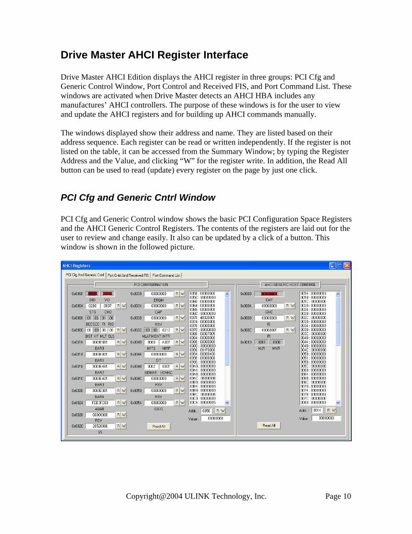
Drive Master AHCI Register Interface Drive Master AHCI Edition displays the AHCI register in three groups: PCI Cfg and Generic Control Window, Port Control and Received FIS, and Port Command List. These windows are activated when Drive Master detects an AHCI HBA includes any manufactures’ AHCI controllers. The purpose of these windows is for the user to view and update the AHCI registers and for building up AHCI commands manually. The windows displayed show their address and name. They are listed based on their address sequence. Each register can be read or written independently. If the register is not listed on the table, it can be accessed from the Summary Window; by typing the Register Address and the Value, and clicking “W” for the register write. In addition, the Read All button can be used to read (update) every register on the page by just one click.
PCI Cfg and Generic Cntrl Window PCI Cfg and Generic Control window shows the basic PCI Configuration Space Registers and the AHCI Generic Control Registers. The contents of the registers are laid out for the user to review and change easily. It also can be updated by a click of a button. This window is shown in the followed picture.
Copyright@2004 ULINK Technology, Inc. Page 10
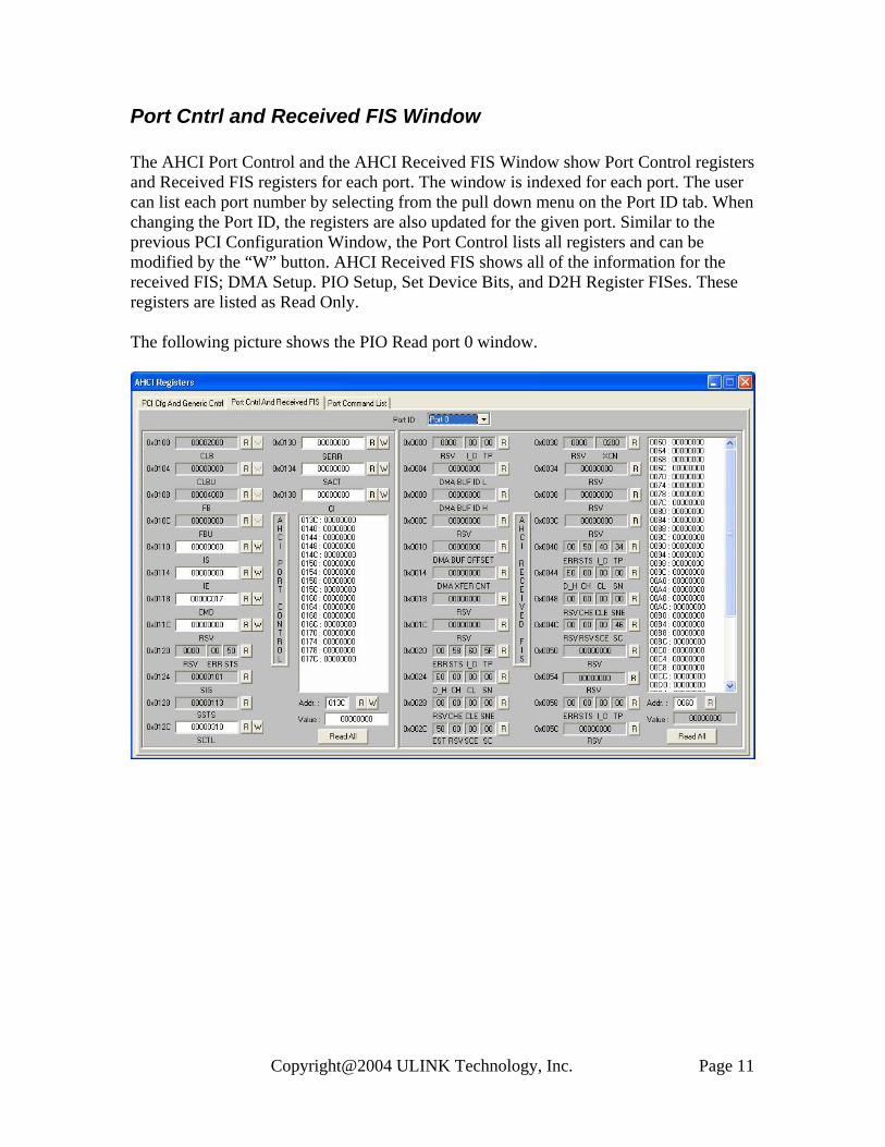
Port Cntrl and Received FIS Window The AHCI Port Control and the AHCI Received FIS Window show Port Control registers and Received FIS registers for each port. The window is indexed for each port. The user can list each port number by selecting from the pull down menu on the Port ID tab. When changing the Port ID, the registers are also updated for the given port. Similar to the previous PCI Configuration Window, the Port Control lists all registers and can be modified by the “W” button. AHCI Received FIS shows all of the information for the received FIS; DMA Setup. PIO Setup, Set Device Bits, and D2H Register FISes. These registers are listed as Read Only. The following picture shows the PIO Read port 0 window.
Copyright@2004 ULINK Technology, Inc. Page 11
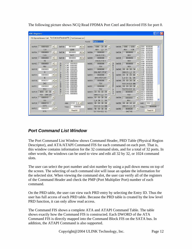
The following picture shows NCQ Read FPDMA Port Cntrl and Received FIS for port 0.
Port Command List Window The Port Command List Window shows Command Header, PRD Table (Physical Region Descriptor), and ATA/ATAPI Command FIS for each command on each port. That is, this window contains information for the 32 command slots, and for a total of 32 ports. In other words, the windows can be used to view and edit all 32 by 32, or 1024 command slots. The user can select the port number and slot number by using a pull down menu on top of the screen. The selecting of each command slot will issue an update the information for the selected slot. When viewing the command slot, the user can verify all of the registers of the Command Header and check the PMP (Port Multiplier Port) number of each command. On the PRD table, the user can view each PRD entry by selecting the Entry ID. Thus the user has full access of each PRD table. Because the PRD table is created by the low level PRD function, it can only allow read access. The Command FIS shows a complete ATA and ATAPI Command Table. The table shows exactly how the Command FIS is constructed. Each DWORD of the ATA Command FIS is directly mapped into the Command Block FIS on the SATA bus. In addition, the ATAPI Command is also supported.
Copyright@2004 ULINK Technology, Inc. Page 12
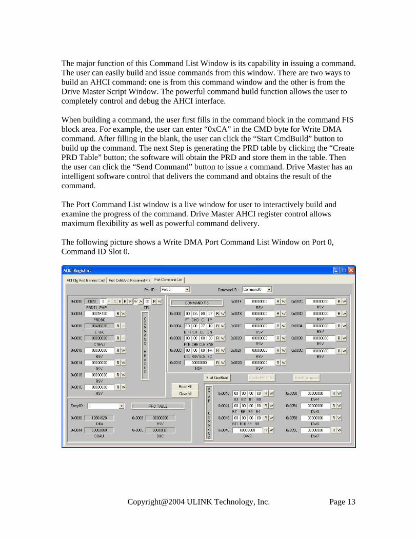
The major function of this Command List Window is its capability in issuing a command. The user can easily build and issue commands from this window. There are two ways to build an AHCI command: one is from this command window and the other is from the Drive Master Script Window. The powerful command build function allows the user to completely control and debug the AHCI interface. When building a command, the user first fills in the command block in the command FIS block area. For example, the user can enter “0xCA” in the CMD byte for Write DMA command. After filling in the blank, the user can click the “Start CmdBuild” button to build up the command. The next Step is generating the PRD table by clicking the “Create PRD Table” button; the software will obtain the PRD and store them in the table. Then the user can click the “Send Command” button to issue a command. Drive Master has an intelligent software control that delivers the command and obtains the result of the command. The Port Command List window is a live window for user to interactively build and examine the progress of the command. Drive Master AHCI register control allows maximum flexibility as well as powerful command delivery. The following picture shows a Write DMA Port Command List Window on Port 0, Command ID Slot 0.
Copyright@2004 ULINK Technology, Inc. Page 13

In addition to the non-queued commands, Drive Master is capable of generating NCQ commands. Normally NCQ commands should be issued from the script in order to have multiple commands on the device queue. When there is a need for debugging, the user can open the Port Command List Window and build a NCQ command on screen. The following window shows a Read FPDMA Queued command (0x60). The Command is located on port number 0, Command ID slot 9.
Copyright@2004 ULINK Technology, Inc. Page 14
Summary Drive Master 2004 – AHCI Edition is designed for engineer and QA people to validate AHCI interface. The function provided in this tool including the followings and more:
1. AHCI Register Display and Editing from Interactive Windows 2. AHCI Register Validation from User Scripts 3. AHCI Function Validation from User Scripts 4. AHCI Command Testing from Interactive Windows 5. AHCI Command Testing from User Scripts 6. Manual and Automated First Party DMA Queue Command Testing 7. NCQ Random Write/Read Data Compare Test 8. NCQ Performance Test 9. SATA Aggressive Power Management Test 10. Port Multiplier Port Test
ULINK believes by providing a powerful, reliable, and flexible third party tool for the AHCI interface, the industry will benefit from the use of this software. Companies can take advantages of this readily available tool to develop their AHCI hardware and software. System companies can use this tool to validate their design on the protocol level. Device companies can use this tool to validate their implementation to the AHCI compatibility. Because of this common software tool, the AHCI implementation can be verified quickly and effectively. Using this tool the AHCI interface will be compatible across the industry. And Drive Master AHCI Edition will help SATA plus AHCI become a greatest successful storage interface.
Copyright@2004 ULINK Technology, Inc. Page 15